JP2012201044A - Printer - Google Patents
Printer Download PDFInfo
- Publication number
- JP2012201044A JP2012201044A JP2011069122A JP2011069122A JP2012201044A JP 2012201044 A JP2012201044 A JP 2012201044A JP 2011069122 A JP2011069122 A JP 2011069122A JP 2011069122 A JP2011069122 A JP 2011069122A JP 2012201044 A JP2012201044 A JP 2012201044A
- Authority
- JP
- Japan
- Prior art keywords
- printing
- recording medium
- printing apparatus
- ink
- unit
- Prior art date
- Legal status (The legal status is an assumption and is not a legal conclusion. Google has not performed a legal analysis and makes no representation as to the accuracy of the status listed.)
- Withdrawn
Links
Images





Landscapes
- Ink Jet (AREA)
Abstract
Description
この発明は、印刷機において画像データに基づいて印刷を行なった記録媒体に対して加熱処理を行なう乾燥手段を備えた印刷装置に関する。 The present invention relates to a printing apparatus including a drying unit that heats a recording medium that has been printed based on image data in a printing machine.
連続した長尺上の記録媒体に印刷を行うインクジェット印刷装置では、複数のローラにより支持されて搬送される記録媒体に対して、複数のインクジェットノズルからインクを吐出させることにより印刷を行っている。記録媒体の搬送路に複数のローラを備える印刷装置では、印刷後の記録媒体を搬送するときに、印刷の表面に当接するローラにインクが転写されることによる装置および印刷物の汚れの発生が問題となる。このため、このような印刷不良の発生を防止する目的で、印刷直後にインクを乾燥させるための乾燥手段を備えた印刷機が提案されている。 In an inkjet printing apparatus that prints on a continuous long recording medium, printing is performed by ejecting ink from a plurality of inkjet nozzles on a recording medium that is supported and conveyed by a plurality of rollers. In a printing apparatus provided with a plurality of rollers in the conveyance path of the recording medium, when conveying the recording medium after printing, there is a problem in that the ink is transferred to the roller in contact with the printing surface and the printed matter is stained. It becomes. For this reason, in order to prevent the occurrence of such a printing defect, a printing machine having a drying means for drying ink immediately after printing has been proposed.
しかしながら、特許文献1に記載の装置では、ヒートローラに記録媒体を接触して乾燥させるため、画像が印刷された部分、すなわちインクの吐出が行なわれた部分(印刷部分)についても、インクの吐出が行なわれなかった、あるいはほとんど行なわれなかった部分(非印刷部分)についても同じ熱量を加える構成となっている。
そのため、インクの吐出が多い(印字量が多い)場合に記録媒体に対して充分な乾燥を行なうための熱量を加えた場合、非印刷部分から蒸発するのはインクの溶媒ではなく記録媒体に含まれる水分であるため、記録媒体にカールやワカメ状のウネリなどの変形が生じることにより、搬送不良や後工程の印刷における不良、あるいは断裁・製本工程における不良が生じる要因となっていた。
However, in the apparatus described in
Therefore, when the amount of heat for sufficient drying is applied to the recording medium when the amount of ink ejected is large (the printing amount is large), it is not the ink solvent but the recording medium that evaporates from the non-printing area. Due to the moisture, the deformation of the recording medium such as curl or seaweed undulation has been a factor in causing poor conveyance, defective printing in the subsequent process, or defective cutting and bookbinding processes.
このような問題は、インクジェット印刷装置のみならず、オフセット印刷機においても生じうる。また、記録媒体が長尺状でなく枚葉状であったとしても、同様の問題は生じ得る。 Such a problem may occur not only in an ink jet printing apparatus but also in an offset printing machine. The same problem can occur even if the recording medium is not a long sheet but a sheet.
そこで、本発明は、上記課題を解決するために、加熱処理による乾燥を記録媒体に対して行なったとしても、非印刷部分の存在により生じる記録媒体の変形を防止する構成を有する印刷機の乾燥装置を提供することを目的とする。
あるいは、非印刷部分の存在により生じる記録媒体の変形を防止する構成を有する乾燥手段を備えた印刷装置を提供することを目的とする。
Accordingly, in order to solve the above problems, the present invention provides a drying machine for a printing press having a configuration that prevents deformation of the recording medium caused by the presence of a non-printing portion even if the recording medium is dried by heat treatment. An object is to provide an apparatus.
Alternatively, an object of the present invention is to provide a printing apparatus including a drying unit having a configuration for preventing deformation of a recording medium caused by the presence of a non-printing portion.
かかる課題を解決する為に、請求項1に記載の発明は、画像データに基づく画像を記録媒体に対して印刷する印刷手段と、前記記録媒体を記録媒体供給部から前記印刷手段へ搬送し、該印刷手段によって印刷が行なわれた前記記録媒体を記録媒体収納部へ搬送する搬送手段と、を備える印刷装置であって、前記搬送手段に、前記印刷手段による印刷後に前記記録媒体が搬送される方向に直交する複数の加熱器を列設した加熱手段と、前記画像データに基づいて前記記録媒体に印刷された画像に対応して前記加熱手段の複数の加熱器の加熱制御を行なう加熱器制御手段と、を有する記録媒体乾燥手段をさらに備えることを特徴としている。
In order to solve such a problem, the invention described in
また、請求項2に記載の発明は、請求項1に記載した印刷装置であって、前記記録媒体乾燥手段の加熱器制御手段は、前記画像データに基づく画像の濃度に対応して、前記加熱手段の複数の加熱器の加熱制御を行なうこと、を特徴としている。
The invention according to
さらに、請求項3に記載の発明は、請求項1に記載した印刷装置であって、前記記録媒体乾燥手段の加熱器制御手段は、前記画像データに基づく画像の画素数に対応して、前記加熱手段の複数の加熱器の加熱制御を行なうこと、を特徴としている。
Furthermore, the invention according to
加えて、請求項4に記載の発明は、請求項1に記載の印刷装置であって、前記記録媒体乾燥手段の加熱器制御手段は、前記記録媒体に印刷された画像を撮影した撮影画像に対応して、前記加熱手段の複数の加熱制御を行なうこと、を特徴としている。
In addition, the invention according to
また、請求項5に記載の発明は、請求項1に記載の印刷装置であって、前記印刷手段がインクジェット印刷であり、前記記録媒体乾燥手段の加熱器制御手段は、前記画像データに基づいて前記印刷手段が行なうインク吐出に対応して、前記加熱手段の複数の加熱器の加熱制御を行なうこと、を特徴としている。
The invention according to
さらに、請求項6に記載の発明は、請求項1に記載の印刷装置であって、前記印刷手段がオフセット印刷であり、前記記録媒体乾燥手段の加熱器制御手段は、前記画像データに基づいて前記印刷手段が行なうインクキー開度に対応して、前記加熱手段の複数の加熱器の加熱制御を行なうこと、を特徴としている。
Further, the invention according to
加えて、請求項7に記載の発明は、請求項1乃至6に記載の印刷装置であって、前記記録媒体乾燥手段の加熱手段の複数の加熱器は、各々前記記録媒体の搬送方向に並行する加熱領域を有すること、を特徴としている。 In addition, a seventh aspect of the invention is the printing apparatus according to the first to sixth aspects, wherein the plurality of heaters of the heating means of the recording medium drying means are each parallel to the conveyance direction of the recording medium. It has the heating area | region which carries out.
また、請求項8に記載の発明は、請求項1乃至7に記載の印刷装置であって、前記記録媒体乾燥手段の加熱手段の複数の加熱器が、赤外線加熱器であること、を特徴としている。
The invention according to
さらに、請求項9に記載の発明は、請求項1乃至7に記載の印刷装置であって、前記記録媒体乾燥手段の加熱手段の複数の加熱器が、マイクロ波加熱器であること、を特徴としている。
The invention described in
請求項1乃至9に記載の印刷装置は、記録媒体の搬送方向に複数の加熱器を列設し、搬送手段に備えられ印刷後の記録媒体に乾燥処理を行なうに際して、該記録媒体に印刷を行なった画像データに基づいて複数の加熱器の加熱制御を行なうことで、印刷部分と非印刷部分とに異なる熱量を加えることにより、非印刷部分からの水分蒸発を防ぐことができるので、記録媒体の変形を防止することができる。
The printing apparatus according to any one of
特に、請求項2に記載の印刷装置は、画像データに基づく画像の濃度に対応して複数の加熱器の加熱制御を行なうことにより、画像濃度の高い部分、すなわちインク吐出が行なわれた部分について強く加熱し、画像濃度の低い部分、すなわちインク吐出がない、あるいはインク吐出が少ない部分について弱く加熱することにより、非印刷部分からの水分蒸発を防ぐことができるので、記録媒体の変形を防止することができる。
In particular, the printing apparatus according to
特に請求項3に記載の印刷装置は、画像データに基づく画像の画素数に対応して複数の加熱器の加熱制御を行なうことにより、画素のある部分、すなわちインク吐出が行なわれた部分について強く加熱し、画素のない部分、すなわちインク吐出がない、あるいはインク吐出が少ない部分について弱く加熱することにより、非印刷部分からの水分蒸発を防ぐことができるので、記録媒体の変形を防止することができる。
In particular, the printing apparatus according to
特に請求項4に記載の印刷装置は、記録媒体に印刷された画像を撮影した撮影画像に対応して複数の加熱器の加熱制御を行なうことにより、印刷がされた部分、すなわちインク吐出が行なわれた部分について強く加熱し、印刷がされなかった部分、すなわちインク吐出がない、あるいはインク吐出が少ない部分について弱く加熱することにより、非印刷部分からの水分蒸発を防ぐことができるので、記録媒体の変形を防止することができる。
In particular, the printing apparatus according to
特に請求項5に記載の印刷装置は、インクジェット印刷装置における画像データに基づいたインク吐出に対応して複数の加熱器の加熱制御を行なうことにより、インク吐出が行なわれた部分について強く加熱し、インク吐出がない、あるいはインク吐出が少ない部分について弱く加熱することにより、非印刷部分からの水分蒸発を防ぐことができるので、記録媒体の変形を防止することができる。 In particular, the printing device according to claim 5 strongly heats a portion where ink is ejected by performing heating control of a plurality of heaters in response to ink ejection based on image data in the ink jet printing device, By weakly heating a portion where there is no ink discharge or little ink discharge, moisture evaporation from the non-printing portion can be prevented, so that deformation of the recording medium can be prevented.
特に請求項6に記載の印刷装置は、オフセット印刷装置における画像データに基づくインクキー開度に対応して複数の加熱器の加熱制御を行なうことにより、インクキー開度が大きい部分について強く加熱し、インクキー開度が小さい部分について弱く加熱することにより、非印刷部分からの水分蒸発を防ぐことができるので、記録媒体の変形を防止することができる。 In particular, the printing apparatus according to claim 6 strongly heats a portion where the ink key opening is large by performing heating control of the plurality of heaters corresponding to the ink key opening based on the image data in the offset printing apparatus. Further, by weakly heating the portion where the ink key opening is small, moisture evaporation from the non-printing portion can be prevented, so that deformation of the recording medium can be prevented.
特に請求項7に記載の印刷装置は、搬送方向に直交して列設された複数の加熱器が、それぞれ記録媒体の搬送方向に並行するように加熱領域を有しているので、搬送される記録媒体に対して充分な加熱を行なうことができる。
In particular, the printing apparatus according to
特に請求項8に記載の印刷装置は、複数の加熱器が赤外線加熱器であることから、印刷部分と非印刷部分とにおける加熱器毎の加熱制御を実行することができる。 Particularly, in the printing apparatus according to the eighth aspect, since the plurality of heaters are infrared heaters, the heating control for each heater in the printing portion and the non-printing portion can be executed.
特に請求項9に記載の印刷装置は、複数の加熱器がマイクロ波発振器であることから、印刷部分と非印刷部分とにおける加熱器毎の加熱制御を実行することができる。 Particularly, in the printing apparatus according to the ninth aspect, since the plurality of heaters are microwave oscillators, the heating control for each heater in the printing portion and the non-printing portion can be executed.
以下、図面を利用しながら、本発明を実施形態について、説明を行なう。 Hereinafter, embodiments of the present invention will be described with reference to the drawings.
〈第1の実施形態〉
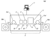
図1は、本発明に関わるインクジェット印刷装置100を説明するための図である。インクジェット印刷装置100は、搬送されるロール紙に対してインクを吐出して印刷を行なう印刷装置である。インクジェット印刷装置100は、制御部1、搬送部2、吐出部3、乾燥部4、検査部5を備える。
<First Embodiment>
FIG. 1 is a diagram for explaining an ink
制御部1は、インクジェット印刷装置100全体を制御するためのものである。制御部1が、搬送部2による用紙9の搬送、吐出部3による用紙9へのインク吐出、乾燥部4におけるインクが吐出された用紙9の乾燥、検査部5における用紙9の印刷像撮影をそれぞれ制御することにより、用紙9に対するインクジェット印刷装置100の印刷を実現している。
The
搬送部2は、インクジェット印刷装置100における用紙9の搬送を行なうための構成であり、用紙収納部20、駆動ローラ21、支持ローラ22を備えている。
用紙収納部20は、印刷を行なうためのロール紙である用紙9を収納するためのものであり、用紙収納部20aは印刷前の用紙9を収納し、用紙収納部20bは印刷後の用紙9を収納する。
用紙収納部20aから引き出された用紙9は、支持ローラ22によって支持されながら駆動ローラ21a、21bによって吐出部3、乾燥部4、検査部5を搬送され、用紙収納部20bに巻取られる。
The
The paper storage unit 20 is for storing the
The
吐出部3は、図示しないインクタンクからインクの供給を受け、制御部1が画像情報に基づいて生成したインク吐出信号によってインクを吐出し、用紙9に対する印刷を行なう。
吐出部3は複数のインクジェットノズル群30として、インクジェットノズル群30k、30c、30m、30yを備えている。インクジェットノズル群30k、30c、30m、30yは用紙9の搬送方向に直交しており、多数のノズルを列設することにより用紙9の搬送幅以上の吐出幅を実現している。吐出部3がこのような構成を備えることにより、吐出部3は用紙9の搬送幅方向に往復走査せずとも一度の吐出で印刷を実行する。
なお、吐出部3のインクジェットノズル群の数は4つに限定されることはなく、単色吐出のためインクジェットノズル群の数は1つであってもよいし、特色を加えた吐出を行なうため5つ以上のインクジェットノズル群を備えていても良い。
The
The
Note that the number of inkjet nozzle groups in the
乾燥部4は、ヒーターにより、吐出部3による印刷後の用紙9に対して熱を加えることにより、インクの溶媒(主に水である)を蒸発させることで、インクの定着を行なう。
乾燥部4は、搬送部2によって搬送される用紙9に対して、搬送方向に直交して跨ぎ越すようにヒーター40を備えている。ヒーター40は制御部1による乾燥処理信号DDに基づいて、用紙9に対する適切な乾燥処理を実行する(詳細は後述する)。
ヒーター40は、印刷される画像データの変化に対応して加熱制御を行なうために、反応性の良い加熱器具を使用することが望ましい。具体的には赤外線加熱器やマイクロ波発振器のように、供給する電圧の変化に追随して対応することで加熱出力の制御を行なうことができる加熱器具を、ヒーター40として使用する。
The drying
The drying
As the heater 40, it is desirable to use a heater having high reactivity in order to perform heating control in response to changes in image data to be printed. Specifically, a heater such as an infrared heater or a microwave oscillator that can control the heating output by responding to changes in the supplied voltage is used as the heater 40.
検査部5は、制御部1が用紙9に行なわれた印刷が良好であるか否かを判定するために、印刷像を撮影する。検査部5は、CCDラインセンサ、あるいはCCDカメラにより、搬送される用紙9に印刷された印刷像を撮影し、制御部1へ撮影情報を送信する。制御部1は、インク吐出を行なうために使用した画像情報と撮影情報とを比較することにより、吐出部3における吐出不良の有無を判定することによって、印刷が良好であるか否かを判定することができる。
また、検査部5は、乾燥部4における乾燥制御に使用するために、用紙9に対して行なった印刷画像を撮影する(詳細は後述する)。
The
Further, the
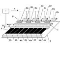
図2は、インクジェット印刷装置100の吐出部3、乾燥部4、検査部5を説明するための図である。
吐出部3は、図示しているように、搬送部2によって搬送される用紙9に対して直交するようインクジェットノズル群30を備えている。ここでは、説明を簡略化するために、1色のみのインクジェットノズル群30を図示しており、インクジェットノズル群30はインクジェットヘッド30a〜30hの8個のインクジェットヘッドで構成されている。
吐出部3のインクジェットノズル群30は、制御部1から送信されたインク吐出信号JDに基づいて、用紙9に対して画像を印刷するため、インクを吐出する。インクジェットノズル群30の幅は、用紙9の搬送方向に直交する幅よりも広いので、用紙9の搬送に応じて所望の画像を印刷することができる。
なお、インクジェットノズル群30を構成するインクジェットヘッドの数は8に限定されることはない。
FIG. 2 is a diagram for explaining the
As shown in the drawing, the
The
The number of inkjet heads constituting the
検査部5は、図示しているように、搬送部2によって搬送される用紙9に対して直交するように備えられ、吐出部3によって用紙9に印刷された画像を撮影する。検査部5によって撮影された印刷画像は撮影情報IDとして、制御部1へ送信される。制御部1は、撮影情報IDと、インク吐出信号JDを作成する元となった画像データGDと比較することにより、用紙9に印刷された画像が良好なものか否かを判断する。
また、検査部5からの撮影情報IDに基づいて、制御部1は乾燥部4の制御を行なう。撮影情報IDから、制御部1は用紙9において画像が印刷された状態を取得することができる。そして、用紙9における画像の印刷状態に応じて、制御部1が乾燥部4の乾燥制御を行なう(詳細は後述する)。
As shown in the drawing, the
Further, the
乾燥部4は、図示しているように、搬送部2によって搬送される用紙9に対して直交するように備えられ、吐出部3によって用紙9に印刷された画像に対して乾燥処理を行なう。
乾燥部4は、所定の管長を有するヒーター40a〜40hによって構成されるヒーター40を備えている。ヒーター40a〜40hの管長は、加熱能力に応じて決定する。すなわち、加熱能力が低ければヒーター40a〜40hの管長を長くして乾燥時間を長くすることにより、用紙9の乾燥処理に対応することが可能となる。一方、加熱能力が高ければヒーター40a〜40hの管長を短くして乾燥時間を短くして用紙9の乾燥処理に対応することが可能となる。
As shown in the drawing, the drying
The drying
乾燥部4のヒーター40a〜40hは、制御部1からの乾燥処理信号DDに基づいて、各々の加熱量が変更される。加熱量の変更は、乾燥処理信号DDに基づく印加電圧量の変更で実行される。すなわち、乾燥処理信号DDを受信した乾燥部4は、該乾燥処理信号DDに基づいて、ヒーター40a〜40hそれぞれに印可すべき電圧量を決定する。例えば、乾燥処理信号DDにおいて、ヒーター40aによる強力な乾燥を行なう指示が含まれていた場合、乾燥部4は、ヒーター40aに対して高電圧を印加する。一方、乾燥処理信号DDにおいて、ヒーター40hにおける乾燥が不要である場合、乾燥部4はヒーター40hに対して電圧を印加しない。ヒーター40a〜40hに対する電圧印可の手法としては、PWM(Pulse Width Modulator)制御を採用することができる。また、直接的に電圧の大小を制御するようにしても良い。
なお、乾燥部4に備えられるヒーター40の数は8に限定されることはない。ヒーター40の数が多数の場合、乾燥部4は、ヒーター40を所定の数で分割して乾燥制御を行なうようにしても良い。所定の数としては、例えばインクジェットノズル群30を構成するインクジェットヘッドの数を採用することができる。
〈濃度に基づく乾燥制御〉
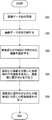
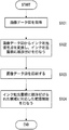
図3は、インクジェット印刷装置100において、画像データに基づく画像の濃度に対応した乾燥制御を説明するためのフローチャートである。
図3に示すインクジェット印刷装置100の動作は、RIPを行なう前、あるいはRIPを行なった後の画像データGDが表現する画像Gを複数の領域に分割し、該分割領域の平均濃度の大小に基づいて、乾燥部4における乾燥処理を実行する態様である。
The heating amounts of the
The number of heaters 40 provided in the
<Drying control based on concentration>
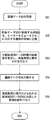
FIG. 3 is a flowchart for explaining the drying control corresponding to the image density based on the image data in the
The operation of the
ステップS31において、インクジェット印刷装置100が印刷を行なうべき画像データGDを取得する。
In step S31, image data GD to be printed by the
ステップS32において、インクジェット印刷装置100の制御部1が、取得した画像データGDについて、乾燥部4のヒーター40a〜40hに対応する複数の領域に分割する。制御部1は、乾燥部4のヒーター40a〜40hが8個であることから、画像データGDが表現する画像Gについて、8領域に分割する。また、分割方向は、ヒーター40a〜40hに平行な方向、すなわち画像データGDを用紙9に印刷する際の用紙9の搬送方向に平行な方向に分割する。
In step S32, the
ステップS33で、制御部1は、画像データGDが表現する画像Gを分割した各領域について画像の平均濃度を算出し、分割領域毎に濃度に基づいた順序を与える。
In step S33, the
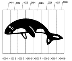
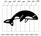
図4は、S32およびS33によって、画像データGDが表現する画像Gを分割した状態を説明するための図である。画像データGDが表現する画像Gは、図示しているように、8個の分割領域であるDGD1〜DGD8に分割されている。この状態で、分割領域DGD1〜DGD8それぞれにおける画像の平均濃度を算出する。
ここでは、図示しているように、分割領域DGD1およびDGD8は画像Gの一部分が領域の一部分を占めているのみなので、平均濃度は低くなる。一方、画像Gの一部分が領域の大部分を占めている分割領域DGD4の平均濃度は高くなる。従って、平均濃度の算出の結果、分割領域毎に濃度に基づいた順序は高い順から「DGD4>DGD3>DGD2>DGD5>DGD7>DGD6>DGD1>DGD8」となる。
FIG. 4 is a diagram for explaining a state in which the image G represented by the image data GD is divided by S32 and S33. The image G represented by the image data GD is divided into eight divided regions DGD1 to DGD8 as shown in the figure. In this state, the average density of the image in each of the divided regions DGD1 to DGD8 is calculated.
Here, as shown in the figure, the divided areas DGD1 and DGD8 have a low average density because only a part of the image G occupies a part of the area. On the other hand, the average density of the divided region DGD4 in which a part of the image G occupies most of the region is high. Accordingly, as a result of the calculation of the average density, the order based on the density for each divided region is “DGD4>DGD3>DGD2>DGD5>DGD7>DGD6>DGD1> DGD8” in descending order.
図3に戻って、ステップS34で、インクジェット印刷装置100は画像データGDを印刷する。画像データGDがRIPされていなければ、制御部1はRIPを行ない二値化画像データに変換して、さらに吐出部3を制御するためのインク吐出信号JDに変換することにより、用紙9に対して画像データGDが表現する画像Gを印刷する。画像データGDがRIPされている二値化画像信号の場合、制御部1は吐出部3を制御するためのインク吐出信号JDに変換し、用紙9に対して画像データGDが表現する画像Gを印刷する。
Returning to FIG. 3, in step S34, the
ステップS35において、用紙9に対して印刷された画像を乾燥するため、制御部1は乾燥部4の制御を行なう。制御部1は、ステップS33で濃度に基づいた順序が与えられた分割領域に対応するヒーター40a〜40hについて、各々加熱量を変更するような乾燥処理信号DDを乾燥部4に送信する。乾燥部4は乾燥処理信号DDに基づいて、ヒーター40a〜40hに印加する電圧を各々変更することにより、ヒーター40a〜40hの加熱量を変更する。
In step S35, the
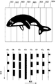
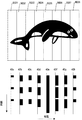
図5は、画像領域の濃度に対応して複数のヒーターの加熱制御を行なっている状態を説明するための図であり、図4に示した画像Gを分割した各分割領域DGD1〜DGD8に対応して、乾燥処理信号DDによるヒーター40a〜40hに印加する電圧の変化を図示している。
FIG. 5 is a diagram for explaining a state in which heating control of a plurality of heaters is performed in accordance with the density of the image region, and corresponds to each of the divided regions DGD1 to DGD8 obtained by dividing the image G shown in FIG. And the change of the voltage applied to the
乾燥処理信号DDは、ヒーター40a〜40h各々の最大出力を100として、8段階に電圧を変化させる信号である。乾燥処理信号DDを受信した乾燥部4は、ヒーター40a〜40h各々に乾燥処理信号DDに基づく電圧を印加する。電圧の印可はPWM制御であることから、周波数は一定で、電圧が一定、パルス幅を異なるようにすることで、印加する平均電圧を変更することができる。
ここでは、分割領域毎に濃度に基づいた順序は高い順から「DGD4>DGD3>DGD2>DGD5>DGD7>DGD6>DGD1>DGD8」となっていることから、印可される電圧が高いヒーターの順序は「40d>40c>40b>40e>40g>40f>40a>40h」となる。
The drying processing signal DD is a signal for changing the voltage in eight stages, with the maximum output of each of the
Here, since the order based on the concentration in each divided region is “DGD4>DGD3>DGD2>DGD5>DGD7>DGD6>DGD1> DGD8”, the order of the heaters with the high applied voltage is as follows. “40d>40c>40b>40e>40g>40f>40a> 40h”.
これにより、画像の平均濃度が高い分割領域、すなわち印刷のためにインクが大量に吐出された領域には強力な乾燥が行なわれ、画像の平均濃度が低い分割領域には弱い乾燥が行なわれることになる。その結果、平均濃度が高い分割領域と平均濃度が低い分割領域とで異なる熱量を加えられることになり、平均濃度が低い分割領域からの水分蒸発を防ぐことができるので、用紙9の変形を防止することができる。
〈画素数に基づく乾燥制御〉
図6は、インクジェット印刷装置100において、画像データに基づく画像の画素数に対応した乾燥制御を説明するためのフローチャートである。
図6に示すインクジェット印刷装置100の動作は、RIPを行なった後の画像データGDが表現する画像Gを複数の領域に分割し、該分割領域の画素数の大小に基づいて、乾燥部4における乾燥処理を実行する態様である。
As a result, strong drying is performed on the divided areas where the average density of the image is high, that is, areas where a large amount of ink is ejected for printing, and weak drying is performed on the divided areas where the average density of the image is low. become. As a result, different amounts of heat can be applied to the divided areas with a high average density and the divided areas with a low average density, and moisture evaporation from the divided areas with a low average density can be prevented. can do.
<Drying control based on the number of pixels>
FIG. 6 is a flowchart for explaining drying control corresponding to the number of pixels of an image based on image data in the
The operation of the
ステップS61で、インクジェット印刷装置100は二値化画像データである画像データGDを取得する。
なお、ステップS61で取得した画像データGDがRIP前ならば、制御部1はRIPを行ない、画像データGDを二値化画像データに変換する。
In step S61, the
If the image data GD acquired in step S61 is before RIP, the
ステップS62で、インクジェット印刷装置1の制御部1は、取得した画像データGDについて、乾燥部4のヒーター40a〜40hに対応する複数の領域に分割する。制御部1は、乾燥部4のヒーター40a〜40hが8個であることから、画像データGDが表現する画像Gについて、8領域に分割する。また、分割方向は、ヒーター40a〜40hに平行な方向、すなわち画像データGDを用紙9に印刷する際の用紙9の搬送方向に分割する。
In step S62, the
ステップS63では、制御部1は画像データGDを分割した各領域における画素数を取得し、分割領域毎に画素数に基づいた順序を与える。
In step S63, the
図7は、ステップS63によって、画像データGDが表現する画像Gを分割した状態を示すための図である。画像データGDが表現する画像Gは、図示しているように、8個の分割領域であるDGD1〜DGD8に分割されている。分割領域DGD1〜DGD8それぞれにおける画像Gを表現するための画素の数を、各領域における画素数として取得する。
ここでは、図示しているように、分割領域DGD1およびDGD8は画像Gの一部分が領域の一部分を占めているのみなので、画像Gを表現する画素数は少ない。一方、画像Gの一部分が領域の大部分を占めている分割領域DGD5の画素数は多くなる。従って、画素数取得の結果、分割領域毎に画素数に基づいた順序は高い順から「DGD5>DGD6>DGD7>DGD4>DGD2>DGD3>DGD8>DGD1」となる。
FIG. 7 is a diagram for illustrating a state in which the image G represented by the image data GD is divided in step S63. The image G represented by the image data GD is divided into eight divided regions DGD1 to DGD8 as shown in the figure. The number of pixels for expressing the image G in each of the divided areas DGD1 to DGD8 is acquired as the number of pixels in each area.
Here, as shown in the drawing, since the divided regions DGD1 and DGD8 only occupy a part of the region, the number of pixels representing the image G is small. On the other hand, the number of pixels in the divided region DGD5 in which a part of the image G occupies most of the region increases. Therefore, as a result of obtaining the number of pixels, the order based on the number of pixels for each divided region is “DGD5>DGD6>DGD7>DGD4>DGD2>DGD3>DGD8> DGD1” in descending order.
図6に戻って、ステップS64で、インクジェット印刷装置100は画像データGDを印刷する。制御部1は画像データGDを吐出部3を制御するためのインク吐出信号JDに変換し、用紙9に対して画像データGDが表現する画像を印刷する。
Returning to FIG. 6, in step S64, the
ステップS65において、用紙9に対して印刷された画像を乾燥するため、制御部1は乾燥部4の制御を行なう。制御部1は、ステップS63で画素数に基づいた順序が与えられた分割領域に対応するヒーター40a〜40hについて、各々加熱量を変更するような乾燥処理信号DDを乾燥部4に送信する。乾燥部4は乾燥処理信号DDに基づいて、ヒーター40a〜40hに印加する電圧を各々変更することにより、ヒーター40a〜40hの加熱量を変更する。
In step S65, the
図8は、画像領域の濃度に対応して複数のヒーターの加熱制御を行なっている状態を説明するための図であり、図7に示した画像Gを分割した各分割領域DGD1〜DGD8に対応して、乾燥処理信号DDによるヒーター40a〜40hに印加する電圧の変化を図示している。
FIG. 8 is a diagram for explaining a state in which heating control of a plurality of heaters is performed in accordance with the density of the image area, and corresponds to each of the divided areas DGD1 to DGD8 obtained by dividing the image G shown in FIG. And the change of the voltage applied to the
乾燥処理信号DDは、ヒーター40a〜40h各々の最大出力を100として、8段階に電圧を変化させる信号である。乾燥処理信号DDを受信した乾燥部4は、ヒーター40a〜40h各々に乾燥処理信号DDに基づく電圧を印加する。電圧の印可はPWM制御であることから、周波数は一定で、電圧が一定、パルス幅を異なるようにすることで、印加する平均電圧を変更することができる。
ここでは、分割領域毎に画素数に基づいた順序は高い順から「DGD5>DGD6>DGD7>DGD4>DGD2>DGD3>DGD8>DGD1」となっていることから、印可される電圧が高いヒーターの順序は「40e>40f>40g>40d>40b>40c>40h>40a」となる。
The drying processing signal DD is a signal for changing the voltage in eight stages, with the maximum output of each of the
Here, since the order based on the number of pixels for each divided region is “DGD5>DGD6>DGD7>DGD4>DGD2>DGD3>DGD8> DGD1” from the highest order, the order of the heaters with the highest applied voltage is high. Is "40e>40f>40g>40d>40b>40c>40h>40a".
これにより、画素数が多い分割領域、すなわち印刷のためにインクが大量に吐出された領域には強力な乾燥が行なわれ、画素数が少ない分割領域には弱い乾燥が行なわれることになる。その結果、画素数が多い分割領域と画素数が少ない分割領域とで異なる熱量を加えられることになり、画素数が少ない分割領域からの水分蒸発を防ぐことができるので、用紙9の変形を防止することができる。
〈印刷画像に基づく乾燥制御〉
図9は、インクジェット印刷装置100において、用紙9に印刷した画像を撮影した印刷画像に基づく乾燥制御を説明するためのフローチャートである。
図9に示すインクジェット印刷装置100の動作は、印刷画像を複数の領域に分割し、該分割領域の画像濃度の大小に基づいて、乾燥部4における乾燥処理を実行する態様である。
As a result, a strong drying is performed on a divided region with a large number of pixels, that is, a region where a large amount of ink is ejected for printing, and a weak drying is performed on a divided region with a small number of pixels. As a result, different amounts of heat can be applied to the divided region with a large number of pixels and the divided region with a small number of pixels, and moisture evaporation from the divided region with a small number of pixels can be prevented, so that deformation of the
<Drying control based on printed images>
FIG. 9 is a flowchart for explaining drying control based on a printed image obtained by photographing an image printed on the
The operation of the
ステップS91で、インクジェット印刷装置100が画像データGDを取得する。
なお、ステップS91で取得した画像データGDがRIP前ならば、制御部1はRIPを行ない、画像データGDを二値化画像データに変換する。
In step S91, the
If the image data GD acquired in step S91 is before RIP, the
ステップS92で、インクジェット印刷装置100は画像データGDを印刷する。制御部1は画像データGDを吐出部3を制御するためのインク吐出信号JDに変換し、用紙9に対して画像データGDが表現する画像Gを印刷する。
In step S92, the
ステップS93で、検査部5が搬送された用紙9に印刷された画像を撮影する。吐出部3によるインク吐出後、搬送部2によって搬送された用紙9は検査部5の下部を通過する。その時、検査部5は用紙9に印刷された画像を撮影し、撮影情報IDとして制御部1へ送信する。
In step S93, the
ステップS94で、制御部1が、撮影情報IDが表現する画像を分割した各領域について画像の平均濃度を算出し、分割領域毎に濃度に基づいた順序を与える。
In step S94, the
ステップS95において、用紙9に対して印刷された画像を乾燥するため、制御部1は乾燥部4の制御を行なう。制御部1は、ステップS94で濃度に基づいた順序が与えられた分割領域に対応するヒーター40a〜40hについて、各々加熱量を変更するような乾燥処理信号DDを乾燥部4に送信する。乾燥部4は乾燥処理信号DDに基づいて、ヒーター40a〜40hに印加する電圧を各々変更することにより、ヒーター40a〜40hの加熱量を変更する。
In step S95, the
これにより、印刷画像の平均濃度が高い分割領域、すなわち印刷のためにインクが大量に吐出された領域には強力な乾燥が行なわれ、画像の平均濃度が低い分割領域には弱い乾燥が行なわれることになる。その結果、平均濃度が高い分割領域と平均濃度が低い分割領域とで異なる熱量を加えられることになり、平均濃度が低い分割領域からの水分蒸発を防ぐことができるので、用紙9の変形を防止することができる。
〈インク吐出信号に基づく乾燥制御〉
図10は、インクジェット印刷装置100において、用紙9に印刷を行なうためのインクを吐出するインクジェットノズル群30に印可されたインク吐出信号JDに基づく乾燥制御を説明するためのフローチャートである。
図10に示すインクジェット印刷装置100の動作は、画像を複数の領域に分割し、該分割領域に対してインクジェットヘッドがインク吐出を行なうためのインク吐出信号に基づいて、乾燥部4における乾燥処理を実行する態様である。
As a result, strong drying is performed on the divided area where the average density of the printed image is high, that is, the area where a large amount of ink is ejected for printing, and weak drying is performed on the divided area where the average density of the image is low. It will be. As a result, different amounts of heat can be applied to the divided areas with a high average density and the divided areas with a low average density, and moisture evaporation from the divided areas with a low average density can be prevented. can do.
<Drying control based on ink ejection signal>
FIG. 10 is a flowchart for explaining the drying control based on the ink ejection signal JD applied to the
The operation of the
ステップS101で、インクジェット印刷装置100が画像データGDを取得する。
なお、ステップS101で取得した画像データGDがRIP前ならば、制御部1はRIPを行ない、画像データGDを二値化画像データに変換する。
In step S101, the
If the image data GD acquired in step S101 is before RIP, the
ステップS102で、制御部1は、画像データGDを吐出部3を制御するためのインク吐出信号JDに変換し、インク吐出量に基づいた順序を与える。吐出部3が備えるインクジェットノズル群30は、インクジェットヘッド30a〜30hを有していることから、制御部1は各インクジェットヘッドからのインク吐出を制御するため、二値化画像である画像データGDから、インク吐出信号JD1〜JD8に変換を行なう。
In step S102, the
インク吐出信号JD1〜JD8は、画像データGDの画素数の大小に応じて、インクの吐出量が異なっている。図11は、インク吐出信号JD1〜JD8と画像データGDの画素数との関係を説明するための図である。画像データGDに基づいて変換されたインク吐出信号JD1〜JD8は、インク吐出の結果、図11に示すような画像Gを用紙9に印刷する。ここで、インクジェットヘッド30a、および30hはインクの吐出量が少ないことから、対応するインク吐出信号JD1、およびJD8はインク吐出量が少ない信号である。一方、インクジェットヘッド40dはインクの吐出量が多いことから、対応するインク吐出信号JD4はインク吐出量が多い信号である。このようにインク吐出量に基づく順序付けの結果、インク吐出信号JDの順序は、インク吐出量の多い順から「JD4>JD3>JD2>JD5>JD7>JD6>JD1>JD8」となる。
The ink discharge signals JD1 to JD8 have different ink discharge amounts depending on the number of pixels of the image data GD. FIG. 11 is a diagram for explaining the relationship between the ink ejection signals JD1 to JD8 and the number of pixels of the image data GD. The ink ejection signals JD1 to JD8 converted based on the image data GD print an image G as shown in FIG. Here, since the ink jet heads 30a and 30h have a small ink discharge amount, the corresponding ink discharge signals JD1 and JD8 are signals with a small ink discharge amount. On the other hand, since the
図10に戻って、ステップS103で、インクジェット印刷装置100は画像データGDを印刷する。制御部1がインク吐出信号JDを吐出部3に送信することにより、吐出部3がインク吐出を行ない用紙9に対して画像データGDが表現する画像を印刷する。
Returning to FIG. 10, in step S103, the
ステップS104において、用紙9に対して印刷された画像を乾燥するため、制御部1は乾燥部4の制御を行なう。制御部1は、ステップS102でインク吐出量に基づいた順序が与えられたインクジェットヘッドに対応するヒーター40a〜40hについて、各々加熱量を変更するような乾燥処理信号DDを乾燥部4に送信する。乾燥部4は乾燥処理信号DDに基づいて、ヒーター40a〜40hに印加する電圧を各々変更することにより、ヒーター40a〜40hの加熱量を変更する。
In step S104, the
ここでは、インク吐出量に基づいた順序は高い順から「JD4>JD3>JD2>JD5>JD7>JD6>JD1>JD8」となっていることから、インク吐出の多いインクジェットヘッドは「30d>30c>30b>30e>30g>30f>30h>30a」となる。従って、印可される電圧が高いヒーターの順序は、インク吐出の多いインクジェットヘッドに対応した「40d>40c>40b>40e>40g>40f>40h>40a」となる。 Here, since the order based on the ink ejection amount is “JD4> JD3> JD2> JD5> JD7> JD6> JD1> JD8” from the highest order, the inkjet head with a large ink ejection is “30d> 30c> 30b> 30e> 30g> 30f> 30h> 30a ". Therefore, the order of the heaters with the high applied voltage is “40d> 40c> 40b> 40e> 40g> 40f> 40h> 40a” corresponding to the ink jet head that discharges many inks.
これにより、印刷のためにインクが大量に吐出された領域には強力な乾燥が行なわれ、インクの吐出量が少ない領域には弱い乾燥が行なわれることになり、インク吐出量が少ない領域からの水分蒸発を防ぐことができるので、用紙9の変形を防止することができる。
As a result, strong drying is performed in a region where a large amount of ink is ejected for printing, and weak drying is performed in a region where the ink ejection amount is small. Since moisture evaporation can be prevented, deformation of the
〈第2の実施形態〉
ここまでの説明では、インクジェット印刷装置100における乾燥制御について説明を行なってきたが、本発明はオフセット印刷装置にも適用可能である。
図12は、オフセット印刷装置100'を説明するための図である。オフセット印刷装置100'は、搬送されるロール紙に対してインクを転写して印刷を行なう印刷装置である。オフセット印刷装置100'は、制御部1'、搬送部2'、転写部3'、乾燥部4'、検査部5'を備える。
<Second Embodiment>
In the description so far, the drying control in the ink
FIG. 12 is a diagram for explaining the offset
制御部1'は、オフセット印刷装置100'全体を制御するためのものである。制御部1'が、搬送部2'による用紙9の搬送、転写部3'による用紙9へのインク転写、乾燥部4'におけるインクが転写された用紙9の乾燥、検査部5'における用紙9の印刷像撮影をそれぞれ制御することにより、用紙9に対するオフセット印刷装置100'の印刷を実現している。
The
搬送部2'は、インクジェット印刷装置100の搬送部2と同様なので、説明を省略する。
Since the
転写部3'は、図示しないインクタンクからインクの供給を受け、刷版に塗布したインクを用紙9に転写することで印刷を行なう。詳細は後述する。
The
乾燥部4'は、ヒーターにより、転写部3'による印刷後の用紙9に対して熱を加えることにより、インクの溶媒(主に油である)を蒸発させることで、インクの定着を行なう。
乾燥部4'は、搬送部2'によって搬送される用紙9に対して、搬送方向に直交して跨ぎ越すようにヒーター40'を備えている。ヒーター40'は、制御部1'による乾燥処理信号DDに基づいて、用紙9に対する適切な乾燥処理を実行する(詳細は後述する)。
ヒーター40'もまた、印刷される画像データの変化に対応して加熱制御を行なうために、反応性の良い加熱器具を使用することが望ましい。具体的には赤外線加熱器やマイクロ波発振器のように、供給する電圧の変化に追随して対応することで加熱出力の制御を行なうことができる加熱器具を、ヒーター40'として使用する。
The drying
The drying
It is desirable that the heater 40 ′ also uses a highly reactive heating device in order to perform heating control in response to changes in image data to be printed. Specifically, a heater such as an infrared heater or a microwave oscillator that can control the heating output by following and responding to changes in the supplied voltage is used as the heater 40 ′.
検査部5'は、制御部1'が用紙9に行なわれた印刷が良好であるか否かを判定するために、印刷像を撮影する。検査部5'は、CCDラインセンサ、あるいはCCDカメラにより、搬送される用紙9に印刷された印刷像を撮影し、制御部1'へ撮影情報を送信する。
The
図13は転写部3'、乾燥部4'を説明するための図である。
なお、ここでは、検査部5'についての説明は省略する。
FIG. 13 is a diagram for explaining the
In addition, description about test | inspection part 5 'is abbreviate | omitted here.
転写部3'は、インクキー31'、インク胴32'、版胴33'、ブランケット胴34'を備えている。
The
インクキー31'は、図示しないインクタンクからインク胴32'へ油性インクを供給する。インクキー31'は、インク胴32'に対してインクを供給するに際して全面的に均一な供給を行なわない。すなわち、刷版Pにおける絵柄面積率に合わせてインク量を変化させて供給するため、インクキー31'は、複数のインクキー31a'〜31h'から構成されている。制御部1'がインクキー31a'〜31h'の開度を各々変更することにより、刷版Pにおける絵柄面積率に対応したインク供給が行なわれる。
The ink key 31 'supplies oil-based ink from an ink tank (not shown) to the ink cylinder 32'. The ink key 31 ′ does not uniformly supply the ink when supplying ink to the
インク胴32'は、インクキー31'から供給されたインクを版胴33'へ供給する。インク胴32'の回転によってインクが練られることにより、粘性の高いインクが滑らかになって版胴33'へ供給される。ここでは、説明のため2つしかインク胴32'を図示していないが、実際には多数の胴によりインク胴32'が構成される。 The ink cylinder 32 'supplies the ink supplied from the ink key 31' to the plate cylinder 33 '. As the ink is kneaded by the rotation of the ink cylinder 32 ', the highly viscous ink is smoothed and supplied to the plate cylinder 33'. Here, only two ink cylinders 32 'are shown for the sake of explanation, but in actuality, the ink cylinder 32' is constituted by a large number of cylinders.
版胴33'は、刷版Pを巻き付けるためのローラである。版胴33'の回転に伴って、図示しない湿し水装置から刷版Pに水が供給され、インク胴32'からインクが供給されると、親油性のある部分(絵柄部分)にインクが載り、親水性のある部分(絵柄のない部分)に湿し水が載る。
The
ブランケット胴34'は、版胴33'からインクのみを転写される。版胴33'の回転に伴ってブランケット胴34'も回転する。この時、版胴33'とブランケット胴34'は接触をしており、ブランケット胴34'はインクのみを転写されるようになっていることから、刷版Pに付着したインクがその領域形状を維持したままブランケット胴34'に転写される。図示しない圧胴とブランケット胴34'との間に用紙9が挟まれ、ブランケット胴34'の回転にあわせてインクの領域形状が用紙9に転写されるので、用紙9に対する画像データGDが表現する画像Gの印刷が実現する。
In the blanket cylinder 34 ', only ink is transferred from the plate cylinder 33'. With the rotation of the plate cylinder 33 ', the blanket cylinder 34' also rotates. At this time, the
乾燥部4'は、図示しているように、搬送部2'によって搬送される用紙9に対して直交するように備えられ、転写部3'によって用紙9に印刷された画像に対して乾燥処理を行なう。乾燥部4'の構成は、乾燥部4とほぼ同様であることから、説明を省略する。
なお、乾燥部4'に備えられるヒーター40'の数は8に限定されることはない。ヒーター40'の数が多数の場合、乾燥部4'は、ヒーター40'を所定の数で分割して乾燥制御を行なうようにしても良い。所定の数としては、例えばインクキー31'の数を採用することができる。
As shown in the figure, the drying
In addition, the number of heaters 40 ′ provided in the
図14は、オフセット印刷装置100'において、画像データに基づく画像のインクキー開度に対応した乾燥制御を説明するためのフローチャートである。
FIG. 14 is a flowchart for explaining the drying control corresponding to the ink key opening degree of the image based on the image data in the offset
図14に示すオフセット印刷装置100'の動作は、版胴33'にインクを供給するための各インクキー31'の開度に基づいて、乾燥部4'における乾燥処理を実行する態様である。
The operation of the offset
ステップS141で、オフセット印刷装置100'の版胴33'に刷版Pを装着する。オフセット印刷装置100'が通常の印刷装置ならば、オフセット印刷装置100'の外部で作成された刷版Pを版胴33'に装着する。オフセット印刷装置100'がデジタル印刷装置ならば、画像データGDを取得し、オフセット印刷装置100'内部で作成した刷版Pを版胴33'へ装着する。
In step S141, the printing plate P is mounted on the
ステップS142において、オフセット印刷装置100'の制御部1'は、各インクキー31'の開度を設定し、開度に基づいて各インクキー31'の順序を決定する。
インクキー31'の開度設定は、刷版Pが表現する絵柄を各インクキー31'に対応するように分割し、該分割領域毎の網点面積率によって、行なう。あるいは、同様の分割を行ない、各分割領域毎の網点数によって、各インクキー31'の開度を設定するようにしても良い。また、オフセット印刷装置100'がデジタル印刷装置の場合、取得した画像データGDが表現する画像Gを各インクキー31'に対応するように分割し、該分割領域毎の濃度や画素数に基づいて、各インクキー31'の開度を設定するようにしても良い。あるいは、手動で各インクキー31'の開度を設定してもよい。
In step S142, the
The opening degree of the ink key 31 ′ is set by dividing the picture represented by the printing plate P so as to correspond to each
各インクキー31'の開度が設定されたならば、制御部1'は、各インクキー31'の開度の大小に基づいて、各インクキー31'の順序を決定する。
図15は、各インクキー31'の開度と、インク転写量との関係を説明するための図である。図示しているように、インクキー31a'〜31h'は、刷版Pによって表現される画像Gを印刷するためのインクを供給するに際して、インク転写量をそれぞれ異なるものとする必要がある。すなわち、インクキー31a'、および31h'は、印刷のためのインク供給量が少なくても良いのに対して、インクキー31d'は印刷のためのインク供給量を多くする必要があるので、インクキー31'の開度は「31d'>31a' or 31h'」となる。同様に、制御部1'はインクキー31'の開度をそれぞれ求め、開度に基づいて各インクキー31'の順序を得る。ここでは、各インクキー31'の開度の高い順から「31e'>31f'>31d'>31g'>31b'>31c'>31h'>31a'」となる。
If the opening degree of each
FIG. 15 is a diagram for explaining the relationship between the opening of each
ステップS143で、転写部3'による用紙9への印刷を行なう。転写部3'は、ステップS142で設定した各インクキー31'の開度に応じた量でインクをインク胴32'へ供給する。インク胴32'では供給されたインクを練り粘性を低下させた後、版胴33'へ供給する。版胴33'は回転しつつ、図示しない湿し水を刷版Pに供給した後、インク胴32'から刷版Pにインクを供給する。刷版Pに形成された親油層に付着したインクは、版胴33'の回転に伴ってブランケット胴34'へ転写される。刷版Pにおける領域形状を維持したままブランケット胴34'に転写されたインクは、圧胴35'との間に挟まれた用紙9に対して転写され、画像データGDが表現する画像Gが用紙9に印刷されることになる。
In step S143, printing on the
ステップS144で、用紙9に対して印刷された画像を乾燥するため、制御部1'は乾燥部4'の制御を行なう。制御部1'は、ステップS142で開度に基づいた順序が与えられた各インクキー31'に対応するヒーター40a'〜40h'について、各々加熱量を変更するような乾燥処理信号DDを乾燥部4'に送信する。乾燥部4'は乾燥処理信号DDに基づいて、ヒーター40a'〜40h'に印加する電圧を各々変更することにより、ヒーター40a'〜40h'の加熱量を変更する。
In step S144, in order to dry the image printed on the
ここでは、各インクキー31'の開度に基づいた順序は高い順から「31d'>31c'>31e'>31f'>31g'>31b'>31h'>31a'」となる。従って、印可される電圧が高いヒーターの順序は、インク転写量の大小に対応した「40d'>40c'>40e'>40f'>40g'>40b'>40h'>40a'」となる。
Here, the order based on the opening degree of each
これにより、印刷のためにインクが大量に転写された領域には強力な乾燥が行なわれ、インクの転写量が少ない領域には弱い乾燥が行なわれることになり、インク転写量が少ない領域からの用紙9に含有される水分蒸発を防ぐことができるので、用紙9の変形を防止することができる。
As a result, strong drying is performed in areas where a large amount of ink has been transferred for printing, and weak drying is performed in areas where the amount of ink transferred is small. Since evaporation of moisture contained in the
〈変形例〉
ここまでの説明では、インクジェット印刷装置、オフセット印刷装置における乾燥装置について説明を行なってきたが、例えばグラヴィア印刷装置、フレキソ印刷装置、孔版印刷装置、凸版印刷装置など、他の印刷手法を採用した印刷装置においても、本発明に関わる乾燥装置は適用可能である。
<Modification>
In the description so far, the drying device in the ink jet printing apparatus and the offset printing apparatus has been described. However, for example, printing using other printing methods such as a gravure printing apparatus, a flexographic printing apparatus, a stencil printing apparatus, and a relief printing apparatus. The drying apparatus according to the present invention can also be applied to the apparatus.
ここまでの説明では、搬送部2はウェブ状の用紙9を搬送するものとして説明を行なってきたが、搬送部2が搬送する用紙9が枚葉紙であってもよい。
In the above description, the
ここまでの説明では、乾燥部4は用紙9の幅の一部分の乾燥を行なうヒーター40が列設されているものとして説明を行なってきたが、ヒーター40の後段に用紙9全幅を乾燥するためのヒーターを備えるようにしても良い。この場合、用紙9の変形を防止する乾燥を行なった後で、用紙9に対してさらに強力な乾燥を行なうことにより、後処理におけるトラブルを防止することができる。
In the description so far, the drying
ここまでの説明では、乾燥部4のヒーター40について、電圧制御を行なうものとして説明を行なってきたが、電流制御でヒーター40の加熱を行なうようにしても良い。
In the above description, the heater 40 of the
1、1' 制御部
2、2' 搬送部
3 吐出部
3' 転写部
4、4' 乾燥部
5、5' 検査部
9 用紙
30、30k、30c、30m、30y インクジェットノズル群
31'、31a'、31b'、31c'、31d'、31e'、31f'、31g'、31h' インクキー
32' インク胴
33' 版胴
34' ブランケット胴
40、40a、40a'、40b、40b'、40c、40c'、40d、40d' 40e、40e'、40f、40f'、40g、40g'、40h、40h' ヒーター
DGD、DGD1、DGD2、DGD3、DGD4、DGD5、DGD6、DGD7、DGD8 分割領域
G 画像
GD 画像データ
DD 乾燥処理情報
ID 撮影情報
JD インク吐出情報
刷版 P
DESCRIPTION OF
DGD, DGD1, DGD2, DGD3, DGD4, DGD5, DGD6, DGD7, DGD8 Divided area
G image
GD image data
DD drying process information
ID shooting information
JD ink ejection information Printing plate P
Claims (9)
前記搬送手段に、
前記印刷手段による印刷後に前記記録媒体が搬送される方向に直交する複数の加熱器を列設した加熱手段と、
前記画像データに基づいて前記記録媒体に印刷された画像に対応して前記加熱手段の複数の加熱器の加熱制御を行なう加熱器制御手段と、
を有する記録媒体乾燥手段をさらに備えることを特徴とする印刷装置。 Printing means for printing an image based on image data on a recording medium, and the recording medium conveyed from the recording medium supply section to the printing means, and the recording medium printed by the printing means is stored in a recording medium storage section A printing device comprising a conveying means for conveying to
In the conveying means,
A heating unit in which a plurality of heaters orthogonal to the direction in which the recording medium is conveyed after printing by the printing unit;
Heater control means for performing heating control of a plurality of heaters of the heating means corresponding to an image printed on the recording medium based on the image data;
A printing apparatus, further comprising: a recording medium drying unit.
前記記録媒体乾燥手段の加熱器制御手段は、前記画像データに基づく画像の濃度に対応して、前記加熱手段の複数の加熱器の加熱制御を行なうこと、
を特徴とする印刷装置。 The printing apparatus according to claim 1,
The heater control means of the recording medium drying means performs heating control of the plurality of heaters of the heating means in accordance with the density of the image based on the image data.
A printing apparatus characterized by the above.
前記記録媒体乾燥手段の加熱器制御手段は、前記画像データに基づく画像の画素数に対応して、前記加熱手段の複数の加熱器の加熱制御を行なうこと、
を特徴とする印刷装置。 The printing apparatus according to claim 1,
The heater control means of the recording medium drying means performs heating control of a plurality of heaters of the heating means corresponding to the number of pixels of the image based on the image data.
A printing apparatus characterized by the above.
前記記録媒体乾燥手段の加熱器制御手段は、前記記録媒体に印刷された画像を撮影した撮影画像に対応して、前記加熱手段の複数の加熱制御を行なうこと、
を特徴とする印刷装置。 The printing apparatus according to claim 1,
The heater control means of the recording medium drying means performs a plurality of heating controls of the heating means in response to a photographed image obtained by photographing an image printed on the recording medium;
A printing apparatus characterized by the above.
前記印刷手段がインクジェット印刷であり、
前記記録媒体乾燥手段の加熱器制御手段は、前記画像データに基づいて前記印刷手段が行なうインク吐出に対応して、前記加熱手段の複数の加熱器の加熱制御を行なうこと、
を特徴とする印刷装置。 The printing apparatus according to claim 1,
The printing means is inkjet printing;
The heater control unit of the recording medium drying unit performs heating control of the plurality of heaters of the heating unit in response to ink ejection performed by the printing unit based on the image data;
A printing apparatus characterized by the above.
前記印刷手段がオフセット印刷であり、
前記記録媒体乾燥手段の加熱器制御手段は、前記画像データに基づいて前記印刷手段が行なうインクキー開度に対応して、前記加熱手段の複数の加熱器の加熱制御を行なうこと、
を特徴とする印刷装置。 The printing apparatus according to claim 1,
The printing means is offset printing;
The heater control means of the recording medium drying means performs heating control of a plurality of heaters of the heating means corresponding to the ink key opening degree performed by the printing means based on the image data;
A printing apparatus characterized by the above.
前記記録媒体乾燥手段の加熱手段の複数の加熱器は、各々前記記録媒体の搬送方向に並行する加熱領域を有すること、
を特徴とする印刷装置。 The printing apparatus according to claim 1, wherein:
The plurality of heaters of the heating means of the recording medium drying means each have a heating region parallel to the conveyance direction of the recording medium;
A printing apparatus characterized by the above.
前記記録媒体乾燥手段の加熱手段の複数の加熱器が、赤外線加熱器であること、
を特徴とする印刷装置。 The printing apparatus according to claim 1, wherein:
The plurality of heaters of the heating means of the recording medium drying means are infrared heaters;
A printing apparatus characterized by the above.
前記記録媒体乾燥手段の加熱手段の複数の加熱器が、マイクロ波加熱器であること、
を特徴とする印刷装置。 The printing apparatus according to claim 1, wherein:
The plurality of heaters of the heating means of the recording medium drying means are microwave heaters;
A printing apparatus characterized by the above.
Priority Applications (1)
| Application Number | Priority Date | Filing Date | Title |
|---|---|---|---|
| JP2011069122A JP2012201044A (en) | 2011-03-28 | 2011-03-28 | Printer |
Applications Claiming Priority (1)
| Application Number | Priority Date | Filing Date | Title |
|---|---|---|---|
| JP2011069122A JP2012201044A (en) | 2011-03-28 | 2011-03-28 | Printer |
Publications (1)
| Publication Number | Publication Date |
|---|---|
| JP2012201044A true JP2012201044A (en) | 2012-10-22 |
Family
ID=47182503
Family Applications (1)
| Application Number | Title | Priority Date | Filing Date |
|---|---|---|---|
| JP2011069122A Withdrawn JP2012201044A (en) | 2011-03-28 | 2011-03-28 | Printer |
Country Status (1)
| Country | Link |
|---|---|
| JP (1) | JP2012201044A (en) |
Cited By (5)
| Publication number | Priority date | Publication date | Assignee | Title |
|---|---|---|---|---|
| JP2016112855A (en) * | 2014-12-17 | 2016-06-23 | 株式会社リコー | Dryer and inkjet image formation apparatus |
| US9440459B1 (en) * | 2015-08-26 | 2016-09-13 | Xerox Corporation | System and method for treating surface of media with a digitally addressable dryer array to reduce moisture gradient and media cockle |
| JP2017007152A (en) * | 2015-06-18 | 2017-01-12 | 大日本印刷株式会社 | Printing system |
| JP2017065160A (en) * | 2015-09-30 | 2017-04-06 | 富士フイルム株式会社 | Drying apparatus, inkjet recording apparatus, and drying method |
| JP2019006071A (en) * | 2017-06-28 | 2019-01-17 | 京セラドキュメントソリューションズ株式会社 | Inkjet recording device |
-
2011
- 2011-03-28 JP JP2011069122A patent/JP2012201044A/en not_active Withdrawn
Cited By (6)
| Publication number | Priority date | Publication date | Assignee | Title |
|---|---|---|---|---|
| JP2016112855A (en) * | 2014-12-17 | 2016-06-23 | 株式会社リコー | Dryer and inkjet image formation apparatus |
| JP2017007152A (en) * | 2015-06-18 | 2017-01-12 | 大日本印刷株式会社 | Printing system |
| US9440459B1 (en) * | 2015-08-26 | 2016-09-13 | Xerox Corporation | System and method for treating surface of media with a digitally addressable dryer array to reduce moisture gradient and media cockle |
| JP2017065160A (en) * | 2015-09-30 | 2017-04-06 | 富士フイルム株式会社 | Drying apparatus, inkjet recording apparatus, and drying method |
| JP2019006071A (en) * | 2017-06-28 | 2019-01-17 | 京セラドキュメントソリューションズ株式会社 | Inkjet recording device |
| US11061354B2 (en) | 2017-06-28 | 2021-07-13 | Kyocera Document Solutions Inc. | Inkjet recording apparatus |
Similar Documents
| Publication | Publication Date | Title |
|---|---|---|
| JP5011318B2 (en) | Waterless printing system and waterless printing method | |
| US8870361B2 (en) | Printing device, printing method, sheet-fed printing press, and rotary printing press | |
| CN103909727B (en) | For reducing the roll web wasted control and its method | |
| US7207269B2 (en) | Coating material applying method and coating material applying apparatus for applying a coating material to surfaces of prints, and a printing machine having the coating material applying apparatus | |
| JP6409125B2 (en) | INKING DEVICE FOR PRINTING MACHINE, PRINTING MACHINE INCLUDING THE SAME, AND METHOD FOR PRODUCING VIBRATOR ROLLER | |
| JP2021028140A (en) | Control device and program | |
| US20110088577A1 (en) | Method and apparatus for compensating for inking differences in printing presses with an anilox short inking unit and printing press having the apparatus | |
| CN101389486B (en) | Apparatus and methods for high speed variable printing | |
| JP2014148138A (en) | Printer | |
| JP2010531751A (en) | Method of printing on the printing material | |
| CN101495314A (en) | Printing unit of a web-fed rotary printing press | |
| JP7353230B2 (en) | Systems and devices for attenuating curl on substrates printed by inkjet printers | |
| JP2014128932A (en) | Image recording device and test chart output method | |
| EP2569157A1 (en) | An imaging apparatus for flexographic printing | |
| JP3655552B2 (en) | Dampening water supply device and printing device | |
| JP7849196B2 (en) | Printing apparatus and foil transfer method | |
| US11628665B2 (en) | Digital ink application module and methods thereof | |
| JPH0919998A (en) | Printing method and printing machine | |
| JP2005231136A (en) | Flexographic printing machine | |
| JP2019104155A (en) | Image recorder and image recording method | |
| JP6677544B2 (en) | Double-sided burnishing machine | |
| EP1354700B1 (en) | Process for handling renewable imageable printing plates or cylinders in printing machines | |
| JP2015168229A (en) | Printing method | |
| JP2010173310A (en) | Dampening water feeder and offset printing machine | |
| JP2011168050A (en) | Variable printing lithographic printing press |
Legal Events
| Date | Code | Title | Description |
|---|---|---|---|
| A300 | Withdrawal of application because of no request for examination |
Free format text: JAPANESE INTERMEDIATE CODE: A300 Effective date: 20140603 |