JP2012201364A - Hydraulic membrane pump assembly for air maintaining tire - Google Patents
Hydraulic membrane pump assembly for air maintaining tire Download PDFInfo
- Publication number
- JP2012201364A JP2012201364A JP2012067811A JP2012067811A JP2012201364A JP 2012201364 A JP2012201364 A JP 2012201364A JP 2012067811 A JP2012067811 A JP 2012067811A JP 2012067811 A JP2012067811 A JP 2012067811A JP 2012201364 A JP2012201364 A JP 2012201364A
- Authority
- JP
- Japan
- Prior art keywords
- tire
- air
- air chamber
- compression
- valve member
- Prior art date
- Legal status (The legal status is an assumption and is not a legal conclusion. Google has not performed a legal analysis and makes no representation as to the accuracy of the status listed.)
- Granted
Links
- 239000012528 membrane Substances 0.000 title 1
- 230000006835 compression Effects 0.000 claims abstract description 147
- 238000007906 compression Methods 0.000 claims abstract description 147
- 230000004044 response Effects 0.000 claims abstract description 11
- 238000012423 maintenance Methods 0.000 claims description 19
- 239000011324 bead Substances 0.000 claims description 12
- 239000000463 material Substances 0.000 claims description 10
- 239000000203 mixture Substances 0.000 claims description 5
- 238000011084 recovery Methods 0.000 claims description 3
- 238000005452 bending Methods 0.000 description 17
- 239000000853 adhesive Substances 0.000 description 9
- 230000001070 adhesive effect Effects 0.000 description 9
- 230000000712 assembly Effects 0.000 description 6
- 238000000429 assembly Methods 0.000 description 6
- 239000003190 viscoelastic substance Substances 0.000 description 6
- 238000007789 sealing Methods 0.000 description 5
- 230000009471 action Effects 0.000 description 4
- 230000007423 decrease Effects 0.000 description 3
- 230000002441 reversible effect Effects 0.000 description 3
- 239000007787 solid Substances 0.000 description 3
- 230000002528 anti-freeze Effects 0.000 description 2
- 230000000295 complement effect Effects 0.000 description 2
- 230000008878 coupling Effects 0.000 description 2
- 238000010168 coupling process Methods 0.000 description 2
- 238000005859 coupling reaction Methods 0.000 description 2
- 125000004122 cyclic group Chemical group 0.000 description 2
- 239000012530 fluid Substances 0.000 description 2
- 238000005086 pumping Methods 0.000 description 2
- XLYOFNOQVPJJNP-UHFFFAOYSA-N water Substances O XLYOFNOQVPJJNP-UHFFFAOYSA-N 0.000 description 2
- 241000254043 Melolonthinae Species 0.000 description 1
- 239000000654 additive Substances 0.000 description 1
- 238000013459 approach Methods 0.000 description 1
- 230000000903 blocking effect Effects 0.000 description 1
- 238000004891 communication Methods 0.000 description 1
- 150000001875 compounds Chemical class 0.000 description 1
- 238000010276 construction Methods 0.000 description 1
- 230000008602 contraction Effects 0.000 description 1
- 238000012937 correction Methods 0.000 description 1
- 238000010586 diagram Methods 0.000 description 1
- 238000009792 diffusion process Methods 0.000 description 1
- 239000010419 fine particle Substances 0.000 description 1
- 239000000446 fuel Substances 0.000 description 1
- 239000011159 matrix material Substances 0.000 description 1
- 239000002184 metal Substances 0.000 description 1
- 238000000034 method Methods 0.000 description 1
- 238000012986 modification Methods 0.000 description 1
- 230000004048 modification Effects 0.000 description 1
- 238000012544 monitoring process Methods 0.000 description 1
- 230000000737 periodic effect Effects 0.000 description 1
- 230000008855 peristalsis Effects 0.000 description 1
- 239000004033 plastic Substances 0.000 description 1
- 230000001681 protective effect Effects 0.000 description 1
- 230000001105 regulatory effect Effects 0.000 description 1
- 230000000284 resting effect Effects 0.000 description 1
- 230000011218 segmentation Effects 0.000 description 1
- 239000000126 substance Substances 0.000 description 1
- 230000001360 synchronised effect Effects 0.000 description 1
- 229920001169 thermoplastic Polymers 0.000 description 1
- 239000004416 thermosoftening plastic Substances 0.000 description 1
- 239000011800 void material Substances 0.000 description 1
Images


Classifications
-
- B—PERFORMING OPERATIONS; TRANSPORTING
- B60—VEHICLES IN GENERAL
- B60C—VEHICLE TYRES; TYRE INFLATION; TYRE CHANGING; CONNECTING VALVES TO INFLATABLE ELASTIC BODIES IN GENERAL; DEVICES OR ARRANGEMENTS RELATED TO TYRES
- B60C23/00—Devices for measuring, signalling, controlling, or distributing tyre pressure or temperature, specially adapted for mounting on vehicles; Arrangement of tyre inflating devices on vehicles, e.g. of pumps or of tanks; Tyre cooling arrangements
- B60C23/02—Signalling devices actuated by tyre pressure
- B60C23/04—Signalling devices actuated by tyre pressure mounted on the wheel or tyre
- B60C23/0491—Constructional details of means for attaching the control device
- B60C23/0493—Constructional details of means for attaching the control device for attachment on the tyre
-
- B—PERFORMING OPERATIONS; TRANSPORTING
- B60—VEHICLES IN GENERAL
- B60C—VEHICLE TYRES; TYRE INFLATION; TYRE CHANGING; CONNECTING VALVES TO INFLATABLE ELASTIC BODIES IN GENERAL; DEVICES OR ARRANGEMENTS RELATED TO TYRES
- B60C23/00—Devices for measuring, signalling, controlling, or distributing tyre pressure or temperature, specially adapted for mounting on vehicles; Arrangement of tyre inflating devices on vehicles, e.g. of pumps or of tanks; Tyre cooling arrangements
- B60C23/10—Arrangement of tyre-inflating pumps mounted on vehicles
- B60C23/12—Arrangement of tyre-inflating pumps mounted on vehicles operated by a running wheel
- B60C23/121—Arrangement of tyre-inflating pumps mounted on vehicles operated by a running wheel the pumps being mounted on the tyres
-
- B—PERFORMING OPERATIONS; TRANSPORTING
- B60—VEHICLES IN GENERAL
- B60C—VEHICLE TYRES; TYRE INFLATION; TYRE CHANGING; CONNECTING VALVES TO INFLATABLE ELASTIC BODIES IN GENERAL; DEVICES OR ARRANGEMENTS RELATED TO TYRES
- B60C23/00—Devices for measuring, signalling, controlling, or distributing tyre pressure or temperature, specially adapted for mounting on vehicles; Arrangement of tyre inflating devices on vehicles, e.g. of pumps or of tanks; Tyre cooling arrangements
- B60C23/10—Arrangement of tyre-inflating pumps mounted on vehicles
- B60C23/12—Arrangement of tyre-inflating pumps mounted on vehicles operated by a running wheel
- B60C23/135—Arrangement of tyre-inflating pumps mounted on vehicles operated by a running wheel activated due to tyre deformation
Landscapes
- Engineering & Computer Science (AREA)
- Mechanical Engineering (AREA)
- Tires In General (AREA)
Abstract
Description
本発明は、概して空気維持タイヤに関し、特に、一体型空気ポンピングシステムを有する空気維持タイヤに関する。 The present invention relates generally to air maintenance tires, and more particularly to an air maintenance tire having an integrated air pumping system.
通常の空気拡散によって、時間の経過とともにタイヤ圧が低下する。タイヤの自然な状態は、空気圧が不足した状態である。したがって、運転者は、繰り返しタイヤ圧を維持する手段を講じなければならない。そうしないと、燃費が悪くなり、タイヤの寿命が短くなり、車輌の制動・ハンドリング性能が低下する。タイヤ圧が著しく低くなったときに運転者に警告するタイヤ圧監視システム(TPMS)が提案されている。 With normal air diffusion, the tire pressure decreases with time. The natural condition of the tire is the lack of air pressure. Therefore, the driver must take measures to maintain the tire pressure repeatedly. Otherwise, the fuel consumption will deteriorate, the tire life will be shortened, and the braking / handling performance of the vehicle will deteriorate. A tire pressure monitoring system (TPMS) has been proposed that warns the driver when the tire pressure becomes significantly low.
しかし、このようなシステムでも、依然として、運転者が、タイヤを推奨空気圧まで再膨張させるよう警告されたときに是正措置を講じる必要がある。したがって、タイヤ内の空気圧を自動的に維持する空気維持機能をタイヤ内に組み込むことが望ましい。 However, such systems still require corrective action when the driver is warned to reinflate the tires to the recommended air pressure. Therefore, it is desirable to incorporate an air maintenance function in the tire that automatically maintains the air pressure in the tire.
本発明の一態様では、空気維持タイヤシステムは、タイヤカーカスに取り付けられ、タイヤの回転時にタイヤが変形することによって作動するように構成された圧縮アクチュエータと、タイヤカーカスに固定され、圧縮アクチュエータに固定されかつ内部空気チャンバを有する圧縮体を含むポンプ組立体とを有し、空気チャンバが、空気を内部空気チャンバに導入する入口開口部と、空気を内部空気チャンバからタイヤ空洞部まで導く出口開口部とを有する。空気圧縮体は、内部空気チャンバ内の内部空気チャンバの互いに向かい合うそれぞれの端部の所に配置されたピストン弁部材および出口弁部材をさらに含み、ピストン弁と出口弁部材が、圧縮アクチュエータによる作動に応答して内部空気チャンバ内でそれぞれの開位置と閉位置との間を移動し、それによって、空気圧縮サイクル中で入口開口部および出口開口部を周期的に開放し閉鎖する。 In one aspect of the present invention, an air maintenance tire system is attached to a tire carcass and is configured to operate when the tire is deformed when the tire rotates, and is fixed to the tire carcass and fixed to the compression actuator. And a pump assembly including a compression body having an internal air chamber, wherein the air chamber introduces air into the internal air chamber and an outlet opening that directs air from the internal air chamber to the tire cavity And have. The air compressor further includes a piston valve member and an outlet valve member disposed at respective opposing ends of the internal air chamber within the internal air chamber, the piston valve and the outlet valve member being adapted for operation by the compression actuator. In response, moves between respective open and closed positions within the internal air chamber, thereby periodically opening and closing the inlet and outlet openings in the air compression cycle.
他の態様では、ピストン弁部材は、入口開口部に対する開位置にあるとき、空気が入口開口部から空気チャンバ内に流れるのを可能にし、入口開口部に対して閉位置にあるとき、空気が入口開口部から空気チャンバ内への流れるのを妨げ、ピストン弁部材は、開位置と閉位置との間を移動する間、空気チャンバ内のある量の空気を圧縮するように動作する。 In other aspects, the piston valve member allows air to flow from the inlet opening into the air chamber when in the open position relative to the inlet opening and when in the closed position relative to the inlet opening. Preventing flow from the inlet opening into the air chamber, the piston valve member operates to compress a quantity of air in the air chamber while moving between the open and closed positions.
他の態様では、出口弁部材は、出口開口部に対する閉位置にあるとき、空気チャンバ内の空気圧が事前に設定されたしきい値に達したことに応答して開位置へ移動するように動作し、空気が空気チャンバから出口開口部内に流れるのを可能にする。 In another aspect, when the outlet valve member is in a closed position relative to the outlet opening, the outlet valve member operates to move to the open position in response to the air pressure in the air chamber reaching a preset threshold. And allows air to flow from the air chamber into the outlet opening.
空気維持システムは、他の態様によれば、圧縮アクチュエータは、弾性変形可能な材料組成で形成され、ある量の非圧縮性媒体を含む中空の格納体である。格納体は、タイヤカーカスの比較的たわみ変形度の高い領域に固定され、回転するタイヤ内のタイヤ高たわみ変形度領域が変形し回復することに応答して変形状態と非変形状態との間で交互に変形する。アクチュエータ格納体は、変形状態であるとき、加圧され排出されたある量の非圧縮性媒体を排出させ、加圧され排出されたある量の非圧縮性媒体が、ピストン弁部材面に対する圧縮力を発生させてピストン弁を空気チャンバ内の開位置と閉位置との間を移動させる。 According to another aspect of the air maintenance system, the compression actuator is a hollow enclosure formed of an elastically deformable material composition and containing a quantity of incompressible medium. The containment body is fixed in a relatively high deflection deformation region of the tire carcass, and in response to deformation and recovery of the tire high deflection deformation region in the rotating tire, between the deformed state and the non-deformed state. It transforms alternately. When the actuator housing is in the deformed state, the pressurized and discharged amount of the incompressible medium is discharged, and the pressurized and discharged amount of the incompressible medium is compressed with respect to the piston valve member surface. To move the piston valve between an open position and a closed position in the air chamber.
定義
タイヤの「アスペクト比」は、タイヤの断面高さ(SH)と断面幅(SW)との比に100を掛けて百分率で表した値を意味する。
Definition The “aspect ratio” of a tire means a value expressed as a percentage by multiplying the ratio of the sectional height (SH) and the sectional width (SW) of the tire by 100.
「非対称トレッド」は、タイヤの中央面または赤道面EPに対して対称的でないトレッドパターンを有するトレッドを意味する。 “Asymmetric tread” means a tread having a tread pattern that is not symmetrical with respect to the center plane or equatorial plane EP of the tire.
「軸線方向の」および「軸線方向に」は、タイヤの回転軸線に平行なラインまたは方向を意味する。 “Axial” and “axially” mean a line or direction parallel to the tire's axis of rotation.
「チェーファー」は、タイヤビードの外側の周囲に配置され、コードプライがリムに接触して磨耗したり切れたりしないように保護し、かつたわみをリムの上方に分散させる材料の狭いストリップである。 A "chafer" is a narrow strip of material that is placed around the outside of the tire bead, protecting the cord ply from contacting the rim to wear and tear, and distributing the deflection above the rim .
「周方向の」は、軸線方向に垂直な環状トレッドの面の周縁に沿って延びるラインまたは方向を意味する。 “Circumferential” means a line or direction extending along the periphery of the surface of the annular tread perpendicular to the axial direction.
「赤道中央面(CP)」は、タイヤの回転軸に垂直でありかつトレッドの中心を通過する平面を意味する。 “Equatorial center plane (CP)” means a plane perpendicular to the tire's axis of rotation and passing through the center of the tread.
「フットプリント」は、速度が零であり、かつ標準荷重および標準圧力下にあるときにタイヤトレッドが平坦な面に接触する接触部分または接触領域を意味する。 “Footprint” means the contact portion or contact area where the tire tread contacts a flat surface when the velocity is zero and under normal load and pressure.
「溝」は、タイヤ壁の周りを周方向または横方向に延びることができるタイヤ壁内の細長い空隙領域を意味する。「溝幅」は、溝の全長にわたる溝の平均幅に等しい。溝は、後述のように空気チューブを収容するサイズを有する。 “Groove” means an elongated void area in a tire wall that can extend circumferentially or laterally around the tire wall. “Groove width” is equal to the average width of the groove over the entire length of the groove. The groove has a size for accommodating the air tube as described later.
「車内側」は、タイヤが車輪上に取り付けられ、車輪が車輌上に取り付けられたときに車輌に最も近いタイヤの側を意味する。 “Inside the vehicle” means the side of the tire closest to the vehicle when the tire is mounted on a wheel and the wheel is mounted on the vehicle.
「横方向の」は、軸線方向を意味する。 “Lateral” means the axial direction.
「横縁部」は、標準荷重下でタイヤ膨張時に測定したときの、軸線方向で最も外側のトレッド接触部分またはフットプリントに接し、赤道中央面に平行なラインを意味する。 “Lateral edge” means a line that is in contact with the outermost tread contact portion or footprint in the axial direction and is parallel to the equator center plane as measured during tire inflation under standard load.
「正味接触面積」は、トレッドの円周全体に沿った横縁部同士の間の地面に接触するトレッド部材の総面積を、横縁部同士の間のトレッド全体の総面積で割った値を意味する。 "Net contact area" is a value obtained by dividing the total area of the tread member that contacts the ground between the lateral edges along the entire circumference of the tread by the total area of the entire tread between the lateral edges. means.
「非方向性トレッド」は、好ましい順走行方向を有さず、トレッドパターンを好ましい走行方向に揃えるうえで車輌上の特定の1つまたは2つ以上の車輪位置に位置する必要がないトレッドを意味する。逆に、方向性トレッドパターンは、好ましい走行方向を有し、特定の車輪位置を必要とする。 “Non-directional tread” means a tread that does not have a preferred forward running direction and does not need to be located at one or more specific wheel positions on the vehicle to align the tread pattern with the preferred running direction. To do. Conversely, a directional tread pattern has a preferred travel direction and requires a specific wheel position.
「車外側」は、タイヤが車輪上に取り付けられ、車輪が車輌上に取り付けられたときに車輌から最も遠い側を意味する。 “Outside the vehicle” means the side farthest from the vehicle when the tire is mounted on a wheel and the wheel is mounted on the vehicle.
「蠕動」は、空気のような格納された物質を管状の経路に沿って移動させる波状収縮による動作を意味する。 “Peristalsis” refers to an action by wave-like contraction that moves a stored substance, such as air, along a tubular path.
「半径方向の(ラジアル)」および「半径方向に」は、半径方向においてタイヤの回転軸線に向かうかあるいは回転軸線から離れる方向を意味する。 “Radial” and “radially” mean directions in the radial direction toward or away from the tire's axis of rotation.
「リブ」は、少なくとも1つの周方向溝とそのような第2の溝または横縁部とによって形成され、全深さ溝によって横方向に分割されることのないトレッド上の周方向に延びるゴムのストリップを意味する。 A “rib” is a rubber extending in the circumferential direction on a tread formed by at least one circumferential groove and such a second groove or lateral edge and not laterally divided by a full depth groove Means the strip.
「サイプ」は、タイヤのトレッド部材に成形され、トレッド面を細分して牽引を向上させる小さな長穴を意味し、サイプは、全体的に幅が狭く、タイヤのフットプリントで開放されたままである溝とは異なり、タイヤフットプリントでは閉鎖される。 “Sipe” means a small slot that is molded into the tread component of the tire and subdivides the tread surface to improve traction, and the sipe is generally narrow and remains open in the tire footprint Unlike the groove, it is closed in the tire footprint.
「トレッド部材」または「牽引部材」は、溝に隣接する形状を有することによって形成されるリブまたはブロック部材を意味する。 “Tread member” or “traction member” means a rib or block member formed by having a shape adjacent to a groove.
「トレッドアーク幅」は、トレッドの横縁部同士の間で測定されたときのトレッドのアーク長を意味する。 “Tread arc width” means the arc length of the tread as measured between the lateral edges of the tread.
本発明について、一例として、添付の図面を参照して説明する。 The present invention will now be described by way of example with reference to the accompanying drawings.
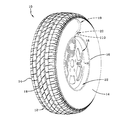
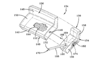
図1、2A、2B、3A、3B、および4を参照すると、本発明の主題である自己膨張式タイヤシステム10が、一対のサイドウォール14と、一対のビード16と、トレッド18とを有する概して従来の構成のタイヤカーカス12を含むように示されている。タイヤカーカス12は、どちらも硬化前組み立て手順においてタイヤに取り付けられるポンプ組立体20および結合された圧縮アクチュエータ組立体19を含むことによって自動膨張するように構成されている。図2Aに示されているように、組立体19は、接着剤領域21として想像線で示されているように接着剤を塗布することによってサイドウォール14に取り付けられてよい。タイヤカーカス12は、タイヤ取り付け面26と、面26から延びる外側リムフランジ24とを有するリム22に従来通りに取り付けられている。タイヤカーカス12はさらに、内部タイヤ空洞部30を形成しかつ囲む内側直線状構成部材28を有するように形成されている。接着剤が、領域21によって示されているインナーライナ28のサイドウォール領域に塗布されている。タイヤカーカス12は、タイヤのビード領域16の近くに下部サイドウォール領域32をさらに有するように形成されている。
1, 2A, 2B, 3A, 3B, and 4, a self-inflating
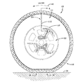
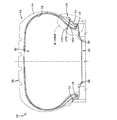
タイヤ組立体10は、車輌に取り付けられ、地面34に係合する。タイヤカーカス12と地面34との間の接触領域はタイヤフットプリント38を表す。圧縮アクチュエータ組立体19は、図3Aおよび3Bに示されているようにタイヤが地面34に対して方向40に回転するときに比較的高いたわみ変形度を有するタイヤカーカス12のサイドウォール領域42に取り付けられている。タイヤが回転すると、圧縮アクチュエータ組立体19およびポンプ組立体20がタイヤと一緒に回転する。圧縮アクチュエータ組立体19は、組立体19が後述の目的のためにタイヤフットプリント38と向かい合って位置するときにサイドウォールがたわむかあるいは屈曲することによって生じる圧縮力を受ける。図3Aおよび断面図の図4は、圧縮アクチュエータ組立体19とポンプ組立体20がタイヤカーカス12の非圧縮領域に位置していることを示し、一方、図3Bおよび断面図の図5は、組立体19および20がタイヤカーカス12の圧縮領域に位置することを示している。図5の位置では、圧縮アクチュエータ組立体19は、タイヤフットプリント38内で発生した圧縮力36を受ける。タイヤは、車輌の通常の動作時には方向40および逆方向に回転する。そのため、互いに結合された組立体19、20は、タイヤと一緒に両方向に回転し、タイヤの順回転方向と逆回転方向の両方においてサイドウォール14内で発生する圧縮力を受ける。
The
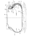
図2A、2B、4、5、6A、6B、6C、6D、および7を参照すると分かるように、圧縮アクチュエータ組立体19は、熱可塑性樹脂および/またはゴム化合物のような弾性変形可能な材料組成で形成された細長い中空の格納体44を含んでいる。そのような構成の格納体44は、それゆえ、曲げ力を受けたときに、変形状態になり、さらに元の非変形状態に回復する周期的な変形を交互にかつ弾性的に受けることができる。図2A、4に示されている細長い格納体44は、トレッド領域18からビード16領域までタイヤサイドウォール14の内側輪郭にだいたい倣うようなサイズおよび形状を有している。格納体44の中空で細長い形状は接着剤領域21の所でタイヤのインナーライナ28に固定するかあるいは後述のようにタイヤサイドウォール14に組み込めるように形状を修正してよい。
As can be seen with reference to FIGS. 2A, 2B, 4, 5, 6A, 6B, 6C, 6D, and 7, the
格納体44は、ある量の非圧縮性媒体48が充填された密閉された中央リザーバキャビティ46を含んでいる。この媒体は発泡形態または流体形態であってよい。本出願で使用するのに適した媒体には、不凍添加剤を含んだ水を含めてよいがこれに限らない。非圧縮性媒体48は、格納体44によって中央リザーバキャビティ46内に密閉され、概ね中央リザーバキャビティ46を充填する。出口導管50が、格納体44に設けられており、格納体44から概ね軸線方向に延びており、排出されたある量の非圧縮性媒体48が往復方向に移動することのできる内側出口導管穴51を含んでいる。出口導管50は、先端面60まで延びている。
The
格納体44は、図2A、2B、4、5に示されているように位置すると、格納体44が取り付けられたサイドウォールの領域がタイヤフットプリントの近くを通過し力36によってトレッド18上に圧縮されるときにタイヤサイドウォール14から曲げ力を受ける(図3B、5)。曲げ力36がかかってサイドウォール領域14が屈曲すると、それに応じて、図6A、6B、6C、および6Dに示されているように媒体格納体44の曲げ変形52が生じる。タイヤサイドウォール14がタイヤフットプリント38の近くで屈曲することによって格納体44に変形52が導入されると、出口導管50に沿って、図6Bの矢印56で示されている方向に非圧縮性媒体48がある量54だけ排出する。媒体の排出量54による圧力は、後述のように圧力アクチュエータとしてポンプ組立体20に作用する。格納体44が取り付けられたタイヤサイドウォール領域が、図6Aに示されているようにタイヤフットプリントと向かい合う位置のようなタイヤフットプリント38に近い位置から離れると、サイドウォールの圧縮力がなくなり/弱まり、それに応じて格納体44への曲げ力がなくなる/弱まる。格納体44における曲げ力がなくなると、格納体44は図4に示されているように元の非変形状態を再開し、非圧縮性媒体48は、出口導管50内に、矢印58で示されている方向に後退する。タイヤが順方向または逆方向に回転する際に、サイドウォールが周期的に屈曲し屈曲から回復すると、格納体44が周期的に変形し変形から復元し、媒体排出量54によって出口導管50に沿った周期的な圧縮力が発生する。媒体排出量54による圧縮力は、方向56に作用し、非圧縮性媒体48の排出量によって発生する圧力に比例する。
When the
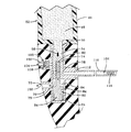
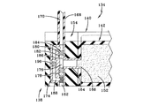
図6A〜6Dおよび7を参照すると分かるように、ポンプ組立体20は、好ましくは組立体19に対して内側半径方向において圧縮アクチュエータ組立体19に隣接する位置でタイヤカーカス12に固定されている。ポンプ組立体20は、チャンバ下端65まで延びる内側軸線方向に配置された空気チャンバ64を有する概ね管状形態の中空の圧縮体62を含んでいる。空気チャンバ64は、入口開口部67の所で空気チャンバ64と交差する入口導管66を通して到達可能である。圧縮体62および入口導管66は金属またはプラスチックのような剛性の材料で形成されている。入口導管66は概ね細長く管状であり、開口部67を介して空気チャンバ64と連通する内側軸線方向通路68を有している。圧縮体62の反対側には、出口導管70を貫通して延び、出口開口部73の所で空気チャンバ64と連通する軸線方向通路72を有する概ね管状形態の出口導管70が位置している。入口導管66と出口導管70は軸線方向においてずれており、入口導管66の方が圧縮アクチュエータ組立体19に近く、出口導管70の方が圧縮アクチュエータ組立体19から遠い。
As can be seen with reference to FIGS. 6A-6D and 7, the
第1の円筒形ピストン部材74は、圧縮体62の軸線方向空気チャンバ64の上端内に滑って配置されるようなサイズを有し、内側ピストン端面75内に延びる軸線方向盲穴76を含んでいる。くぼみ78が、ピストンの、外側に面する側を延びており、弁(組立体96)から出る空気の収集装置として機能する。くぼみ78は、ピストンの角度位置にかかわらず弁とピストン内部の管を連結する。ピストンの、くぼみ78の反対側に、盲穴76と連通する安全弁吸気流路80が延びている。
The first
第2の円筒形ピストン部材82は、圧縮体62の軸線方向空気チャンバ64の下端内に滑って受け入れられるようなサイズを有している。第2のピストン部材82は、円筒体84と、円筒体84から外側端部85まで延びる外側ばね圧縮ポストアーム86とを含んでいる。盲穴88がポストアームの端面85内に延びている。横方向に配置された入口流路90がポストアーム86の側面を貫通して延び、盲穴88と連通している。大型コイルばね94が、圧縮体62内の空気チャンバ64のチャンバ下端65内に嵌るサイズを有している。さらに、より小さなコイルばね92が設けられ、第1のピストン部材74の盲穴76内の表面77に接触している。圧力調整安全弁組立体96が、圧縮体62から延びる内側管状スリーブ98の入口チャンバ99内に取り付けられている。スリーブ98は、チャンバ99から圧縮体62の空気チャンバ64まで延びる入口軸線方向通路97を含んでいる。安全弁組立体96は、外側に延びる管状入口導管102を有する円形体100を含んでいる。貫通穴104が入口導管102および円形体100を貫通して延びている。円板状シール構成部材106が、チャンバ99内の円形体100の内側に位置し、チャンバ99内に配置されたコイルばね108によって外側に円形体100に接触するように偏らされている。
The second
圧縮体の反対側では、内側端部の所の環状当接フランジ112と、チューブ外側端部115から入口チューブ110を貫通して圧縮体62の入口開口部67まで延びる軸線方向通路114とを有する入口チューブ110が、入口導管66に固定されている。軸線方向通路114内のチューブ外側端部115の近くに、微粒子を軸線方向通路114に入らないように除外する多孔フィルタ構成部材116が配置されている。ポンプ組立体20は、サイドウォール14の半径方向下部領域と相補的な形状を有し、圧縮作動体44からタイヤビード領域と向かい合う位置まで延びる外側シースまたはケースメント128内に密閉されている。ケースメント128は、ゴムマトリクスなどの接着剤によってタイヤインナーライナに取り付けるのに適した保護材料で形成されている。
On the opposite side of the compression body, it has an
図4、5、6A、および7に関しては、圧縮アクチュエータ組立体19とポンプ組立体20は、タイヤカーカス12に組み込まれるように図示のように連結されている。圧縮アクチュエータ組立体19は、タイヤが回転するときに高い曲げ荷重を受けるタイヤカーカス12のサイドウォール14の領域に組み込まれている。圧縮アクチュエータ組立体19は、サイドウォール14内に組み込まれても、あるいは図示のように接着剤によってサイドウォール14に固定されてもよい。図示の外部取り付け組立体手法では、格納体44は、それが取り付けられているサイドウォール領域と相補的な形状を有し湾曲しており、かつ概して、トレッド領域18の近くの半径方向外側端部130からサイドウォール取り付け領域に沿って半径方向内側にビード領域の近くの半径方向内側端部132まで延びている。ポンプ組立体20は、接着剤または他の適切な取り付け手段によって組立体19の内側端部132に取り付けられている。ポンプ組立体20は、ゴムなどのタイヤ適合材料で構成された外側ケーシング128内に収容されている。結合された圧縮アクチュエータ組立体19とポンプ組立体20は、接着剤によってタイヤカーカス12のインナーライナ28に取り付けられ、ポンプ組立体20がカーカスビード/下部サイドウォール領域32の近くに位置する。このように位置すると、組立体20の入口チューブ110は、軸線方向にサイドウォール14内を通って外気接触可能な外側タイヤサイドウォール側位置まで突き出る。入口チューブ110の位置は、リムフランジ24よりも上であることが好ましく、それによって、リムフランジ24がポンプ組立体20の入口チューブ110に流入する取り込み空気に干渉することがなくなる。
With reference to FIGS. 4, 5, 6 </ b> A, and 7,
理解されるように、圧縮アクチュエータ組立体19の出口導管50は、アクチュエータ体44の出口導管50が圧縮体62の上端に密封係合して受け入れられたときに圧縮体62の上端に結合される。圧縮体44は、ポンプ組立体20を含むケーシング128に当接している。圧縮アクチュエータ組立体19とポンプ組立体20は、互いに取り付けられた後、図2Aおよび4に示されており上記に説明したようにタイヤサイドウォール14の領域に取り付けられてよい。第1のピストン部材74と第2のピストン部材82は、第2のピストン部材82からのポストアーム86が盲穴76内に突き出て盲穴76内に位置するコイルばね92に接触するときに機械的に結合される。したがって、ピストン部材74、82の軸線方向の移動は、空気チャンバ44内の両半径方向において同期する。
As will be appreciated, the
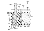
図6A〜6Dは、ポンプ組立体20および圧縮アクチュエータ組立体19の一連の動作を示している。図6Aは、ピストン部材74、82が休止位置にあるポンプ組立体20を示している。図示の位置は、タイヤフットプリントと向かい合う回転位置での、図3Aに示されているように回転するタイヤに取り付けられた組立体19、20の位置と相関する。タイヤフットプリントと向かい合うときに組立体19、20を支持するサイドウォール14領域(図6A)は、タイヤが地面に接触してもたわむことも屈曲することもない。したがって、圧縮アクチュエータ体44は、概して屈曲していないサイドウォール14の曲率と相関する屈曲変形部52を有している。圧縮体44内に密閉された非圧縮性媒体48は、概して休止状態にあり、第1のピストン部材74の端部に接触する導管50内の媒体先端面60に接触している。外側のピストン部材74は、コイルばね92によるばねバイアスの下で空気チャンバ64の外側端部の方へ引き込まれている。
6A-6D show a series of operations of the
図6Aの休止位置では、第1のピストン部材74は軸線方向において入口導管66の入口開口部67よりも上に位置する。その結果、タイヤの外側からの空気がフィルタ116を通して入口チューブ110の軸線方向通路114に流入し、そこから入口導管66の開口部67を通って空気チャンバ64に流入する。矢印118は、流入空気が流れる経路を示している。第2のピストン部材82は空気チャンバ64内の軸線方向に上昇した位置にあり、出口導管70の出口開口部73を遮断している。コイルばね92、94はそれぞれ非圧縮状態にある。安全弁組立体96は通常、タイヤ空洞部30内の圧力が事前に設定された推奨された空気圧よりも低いかぎり閉位置にある。閉位置では、ばね108が円板状シール構成部材106を円形体100を通して入口導管102に接触するように偏らせる。タイヤ空洞部30内の圧力が圧力しきい値を超えた場合、キャビティからの空気圧によって、円板状シール構成部材106が入口導管102から引き離され、空気がタイヤ空洞部30から逃げることができる。
In the rest position of FIG. 6A, the
組立体19、20を保持するサイドウォール14の領域がタイヤフットプリントと向かい合う位置まで回転すると、サイドウォール14がたわんで屈曲し、それに応じて、図6Bの参照番号52で示されているように圧縮アクチュエータ体44がたわむ。図6Bは、粘弾性材料48が、非圧縮性材料の特性を有し、圧縮体44の屈曲に応答して、出口導管50内で下方に押し込まれ、矢印56で示されているように第1のピストン部材74に下向きの圧力をかけていることを示している。非圧縮性媒体48の先端面60は、第1のピストン部材74の外面に接触し、コイルばね92の圧縮によってコイルばね92の抵抗に打ち勝ち、第1のピストン部材74を空気チャンバ64内で下方に移動させる。こうする際に、第1のピストン部材74は、入口チューブ110を通した空気チャンバ64内への空気の流入を遮断する位置に移動し、空気チャンバ64内のある量の空気を圧縮する。空気チャンバ64内の空気の圧力が高くなると、第2のピストン部材82が空気チャンバ64内で下方に押し込まれ、コイルばね94が圧縮される。
As the region of the
第2のピストン部材82が空気チャンバ64内で十分な軸線方向距離にわたって移動すると、図6Cおよび図5に示されているように、第2のピストン部材82による軸線方向通路72への出口開口部73に対する妨害が停止する。したがって、空気チャンバ64からの加圧空気が、矢印126によって示されている方向に、軸線方向通路72を通してタイヤ空洞部30内に押し込まれる。空気の送り込みが完了し、第2のピストン部材82に対する空気チャンバ64内の圧力が中断されると、第2のピストン部材82が軸線方向上方に押されて、図6Dと図6Aの両方に示されている休止位置に戻る。
When the
図6Dを見ると分かるように、空気チャンバ44内のある量の加圧空気のタイヤ空洞部30への移動が完了した後、タイヤがさらに回転すると、図2Aおよび3Aに示されているように、組立体19、20がサイドウォール14の取り付け領域と一緒に、タイヤフットプリントと向かい合う高応力位置から離れ、タイヤサイドウォール領域が応力を受けない状態の湾曲を再開する。サイドウォール14がタイヤフットプリントの外側の元の湾曲形状に戻るとき、それに伴ってかつ同期して、圧縮アクチュエータ体44が屈曲していない形状に戻る。圧縮アクチュエータ体44がその元の湾曲を再開すると、空気チャンバ64からの空気の送り込みサイクルが終了するのに合わせて、第2のピストン部材82が、第1のピストン部材74を半径方向上方に押して移動させるコイルばね94の作用下で軸線方向上方に移動する。粘弾性媒体48は、圧縮体44の元の格納形態に後退し、タイヤ空洞部30内への空気の送り込みは、組立体19、20がタイヤと一緒に回転してタイヤフットプリントに揃って向かい合うまで中断される。回転のたびに、空気チャンバ64からタイヤ空洞部30への空気の送り込みが周期的に行われる。空気送り込み作用が、タイヤの回転方向とは無関係の作用であり、タイヤが順方向に回転する際にも逆方向に回転する際にも生じることが理解されよう。
As can be seen in FIG. 6D, after the movement of an amount of pressurized air in the
図6Dも、ピストン部材74、82が休止位置にあり、一方、安全弁組立体96がタイヤ空洞部30の過圧空気を大気に放出するように働く、ポンプ組立体20の図を示している。安全弁組立体96は通常、図6A〜6Cに示されている閉位置にあり、タイヤ空洞部30内の空気圧が推奨される上限しきい値を超えたときにのみ開く。このような場合、円板状シール構成部材106が、円形体100との密封係合位置から横方向に押し出され、コイルばね108からの偏った抵抗に打ち勝つ。したがって、貫通穴104が開放され、過圧空気が、方向矢印124で示されているように、タイヤ空洞部30から入口導管102および第1のピストン部材74内の安全弁吸気流路80を通過する。加圧された空気は、方向矢印122で示されているように、第1のピストン部材74の盲穴76を通過し、第2のピストン部材82の結合ポスト86内の盲穴88を通過し、入口チューブ110の軸線方向通路114に入る通路を辿る。吐き出された過圧空気はフィルタユニット116を通ってチューブ外側端部115から大気に排出される。空気がフィルタ116を通って排出されると、フィルタによって微粒子が除去されるとともに、タイヤ空洞部30内の過圧が解消される。タイヤ空洞部30の圧力が推奨空気圧しきい値よりも低くなると、コイルばね108が解放され、円板状シール構成部材106を円形体100に押し付け、したがって、タイヤ空洞部30から過圧空気を排出する必要が生じるまでタイヤ空洞部30を閉鎖する。
FIG. 6D also shows a view of the
図9A、9B、10A、10B、11A、11B、12A、12B、13A〜13D、14A〜14Cを参照すると、ポンプ組立体138に結合されL字形インサート体140を形成する圧縮作動組立体136を含むポンプ・圧縮作動組立体134の代替実施形態が示されている。L字形インサート体140は、図10A、10Bに示されているように、タイヤカーカス12の下部サイドウォール領域の、ビード領域16の近くに取り付けられている。圧縮作動組立体136は、出口ポータル146と連通する格納チャンバ144を形成する変形可能な中空体142を有している。中空体142は、水平体部150から延びる直立体部148を有するL字形として90度に構成されている。第1の実施形態を参照して説明したように、非圧縮性材料152上の粘弾性媒体が格納チャンバ144を充填している。
9A, 9B, 10A, 10B, 11A, 11B, 12A, 12B, 13A-13D, 14A-14C, includes a
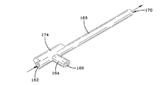
ポンプ組立体138も同様に、L字形の中空体142に固定されたL字形の密封シース体154を形成している。密封シース体154は、水平体部156から延びる直立体部158を含んでいる。出口オリフィス160が水平体部156内に位置し、入口オリフィス162が、水平体部156の側面に面する領域に位置している。出口導管168が、出口オリフィス160に取り付けられており、遠位端170まで延びる軸線方向通路110を含んでいる。
Similarly, the
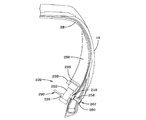
図10Aおよび10Bは、L字形のポンプ・圧縮作動組立体134が下部サイドウォール領域のタイヤビード位置の近くでタイヤに取り付けられることを示している。前述の実施形態と同様に、ポンプ・圧縮作動組立体134は、タイヤが回転するたびに、タイヤと一緒に、タイヤフットプリントの近くの外側の位置(図10A)からタイヤフットプリントと向かい合う位置(図10B)まで回転する。第1の実施形態と同様に、ポンプ・圧縮作動組立体134のL字形インサート体140が、ポンプ・圧縮作動組立体134の回転位置がタイヤフットプリントに揃って向かい合ったときにタイヤサイドウォールが曲がることによって誘起される応力によって屈曲される(図10B)。図11Aおよび11Bは、タイヤが回転したときにL字形インサート体140が強い曲げ力を受ける、サイドウォール14の下部領域内のポンプ・圧縮作動組立体134の相対位置を示している。出口導管168の出口端部172が、タイヤ壁を貫通してタイヤの空洞部30まで延びている。圧縮体174からの圧縮空気が、遠位端部170に沿ってタイヤ空洞部30に入り、タイヤの空気圧を所望のレベルに維持する。
10A and 10B show that an L-shaped pump and
図11Aは、図10Aに示されているタイヤの非圧縮領域内のポンプ位置における断面図である。図11Bは、図11Aのポンプ・圧縮作動組立体134の拡大図である。図12Aは、図10Bに示されているタイヤの圧縮領域内のポンプ位置における断面図である。図12Bは、図12Aに示されているポンプ・圧縮作動組立体134の拡大図である。
FIG. 11A is a cross-sectional view of the pump position in the non-compressed region of the tire shown in FIG. 10A. FIG. 11B is an enlarged view of the pump and
図13A〜13Dおよび14A〜14Cを参照すると分かるように、圧縮体174は、細長い内部圧縮チャンバ176と、圧縮チャンバ176の両側に位置する一対の一方向玉弁178、180とを有している。玉弁178、180の各々は、市販の弁であり、コイルばねによってシート186に偏らされたストップボール構成部材182を含んでいる。また、安全圧力バイパス通路188が圧縮体174内に圧縮チャンバ176に平行に設けられている。安全圧力バイパス通路188内に、一方向玉弁178、180と同様の構成を有する一方向玉弁190が位置している。安全圧力バイパス通路188と圧縮チャンバ176は、圧縮体174の一方の端部の所の出口導管168と反対側の端部の所の入口オリフィス162との間に並列に延びている。
As can be seen with reference to FIGS. 13A-13D and 14A-14C, the
ポンプ組立体138の第1の代替形態の動作は以下の通りに進行する。圧縮作動組立体136は、図10Aおよび10Bによって概略的に示されている位置でタイヤカーカスに埋め込まれるかあるいは固定されている。このように位置すると、ポンプ組立体138が取り付けられたタイヤサイドウォールが屈曲したときに、中空体142も同様に屈曲する。図13Aおよび13Dは、「休止」状態のポンプ組立体138を示しており、すなわち、図10Aのタイヤ位置が表しているように、ポンプ組立体138は曲げ応力を受けていない。一方向玉弁178、180は、閉位置に配置されている。一方向玉弁178、180としては、後述のように所望のしきい値圧力で開く弁が選択される。
Operation of the first alternative form of
休止位置では、圧縮チャンバ176内の空気が圧力を受けなくなる。一方向玉弁190も同様に閉じられ、タイヤ空洞部30内の空気圧が所望の圧力しきい値を超えないかぎり閉じられたままである。過圧状況では、一方向玉弁190が開き、空気を安全圧力バイパス通路188を通じて空洞部30から逃がし、入口開口部162から大気に排出する。圧縮媒体152は、圧縮チャンバ176に拘束されており、入口導管164は遮断されていない。
In the rest position, the air in the
図13Bおよび図12Bは、タイヤがポンプ・圧縮作動組立体134をタイヤフットプリントと向かい合う位置まで回転させたとき(図10B)のポンプ・圧縮作動組立体134を示している。圧縮体174は次いで、曲げ力を受けて変形される。圧縮体174が屈曲すると、粘弾性材料152が格納チャンバ144から入口導管164に入り入口導管164に沿って押され(方向192)、それによって、圧縮チャンバ176内の空気が圧縮される。圧縮空気からの圧力がストップボール構成部材182を解放することによって一方向玉弁180を開き、空気が出口導管168に導入されタイヤ空洞部30まで流れる。
13B and 12B show the pump and
図13Cは、タイヤがさらに回転し、ポンプ・圧縮作動組立体134が、図10Aに示されている位置のようなタイヤフットプリントから離れた位置に配置された後のポンプ・圧縮作動組立体134を示している。圧縮体174に対する曲げ力がなくなると、圧縮体174はその元の形状に戻り、圧縮チャンバ176が、媒体152を入口導管164から後退させる形態に戻る。加圧空気が圧縮チャンバ176から移動すると、一方向玉弁178がそのシート186から解放されることによって大気からの空気が圧縮チャンバ176に引き込まれる。圧縮チャンバ176に引き込まれた空気は、矢印194で示されているように媒体152を格納チャンバ144に戻す。一方向玉弁180は、再び閉じており、空気が圧縮チャンバ176から出ないように遮断している。圧縮チャンバ176の入口端部内のフィルタ部材198が、微粒子が圧縮チャンバ176に流入するのを妨げる。
FIG. 13C shows the pump and
図14Dは、ポンプ・圧縮作動組立体134がその元の休止位置に戻ったことを示している。タイヤ空洞部30内で過圧状況が生じた場合、タイヤ空気圧によって一方向玉弁190が開き、空気が、方向196に流れ、安全圧力バイパス通路188を通過し、フィルタ198を通って大気に排出される。フィルタ198を通る空気の逆流は、フィルタを清浄に維持するのを助ける。第1の実施形態と同様に、ポンプ・圧縮作動組立体134はいずれかのタイヤ回転方向に動作し、各タイヤ回転サイクルの間タイヤ内に空気に送り込む。
FIG. 14D shows that the pump and
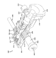
図17A、17B、18A、および18Bを参照すると、タンク式の油圧ポンプ組立体200が、市販の製品で実現可能な構成で示されている。油圧ポンプ組立体200は、前述の図4および7の実施形態と機能が類似している。油圧ポンプ組立体200は、細長い軸線方向穴またはチャンバ204を有する空気圧縮体202を含んでいる。軸線方向チャンバ204は、空気圧縮体202の後方端部208の所で、後方に配置されたピストンチャンバ206に分割されている。圧縮体202の後方端部208は、組み立てのための雄ねじ210を有している。後方ピストンチャンバ206に隣接して中央空気圧縮チャンバ212が位置している。中央空気圧縮チャンバ212には、空気圧縮体202のサイドウォール内を通って中央空気圧縮チャンバ212と連通する管状の入口空気流路214が位置している。外部入口スリーブ216は、入口空気流路214と向かい合う空気圧縮体202の延長部であり、貫通穴218を密閉している。組立体ねじ220が貫通穴218内に位置している。
Referring to FIGS. 17A, 17B, 18A, and 18B, a tank-type
環状のピストンストップフランジ222が、軸線方向穴204に沿ってピストチャンバ206と中央空気圧縮チャンバ212を分離している。中央空気圧縮チャンバ212の、軸線方向穴204に沿った反対側の端部の所に、出口チャンバ224が隣接している。管状の出口スリーブ226が、出口チャンバ224と向かい合う位置で空気圧縮体202に固定されており、貫通穴228および内部組み立てねじ230を含んでいる。環状のストップフランジ232が出口チャンバ224と中央空気圧縮チャンバ212を分離している。軸線方向内部チャンバ236を有するヘッドキャップ部材234が空気圧縮体202の端部208に取り付けられている。ヘッドキャップ部材234は、外側フランジ238と、外側フランジ238に隣接する環状の戻り止め流路237とを含んでいる。ヘッドキャップ部材234は、内部にねじ242を有する円筒体部240を有している。ヘッドキャップ部材234の側壁を貫通して、貫通穴246および雌ねじ248を有する充填導管244が延びている。ねじ部材250は、充填導管244にねじ込まれるねじ252を含んでいる。
An annular
入口導管254は、円筒体256と、入口スリーブ216にねじ込まれるねじ付き端部258とを有している。大径ヘッド260が円筒体256に一体的に接合され、貫通穴262が、入口導管254の両端間を軸線方向に延びている。エンドキャップ部材264が、空気圧縮体202の端部263に固定され、雌ねじ266と端壁268とを含んでいる。中央孔270が壁268を貫通して延びている。コイルばね272が、エンドキャップ部材内に端壁268に接触して配置されている。円筒形弁部材274が、圧縮体202の軸線方向穴204の出口チャンバ224内にコイルばね272に接触して位置している。このように位置すると、弁部材274は、後述のように出口チャンバ224内を軸線方向において順方向および逆方向に滑る。
The
ピストン弁部材280が、圧縮体202の軸線方向穴204のピストンチャンバ206内に位置している。ピストン弁部材280は、大径円形ヘッド282と、大径円形ヘッド282の下側に延びる環状のばね保持溝283とを有している。ピストン弁部材280は、前方端部286まで延びる細長い円筒体284をさらに含んでいる。円筒体284は、コイルばね278内に挿入され、コイルばね278の外側端部がばね保持溝283内に位置するようなサイズを有している。円筒体284の前方端部286は、ピストンチャンバ206内に位置し、図17Aおよび17Bを見ると分かるように、前方に突き出て、圧縮体202の軸線方向穴204の空気圧縮チャンバ212内に密に配置されている。ピストン弁部材280の大径円形ヘッド282の外面288は、圧縮体202の軸線方向穴204に沿って、圧縮体202に取り付けられた大径円形ヘッド282の軸線方向内部チャンバ236に揃う。出口導管290が、ねじ292によって出口スリーブ226に取り付けられており、貫通穴294を貫通穴228に揃えている。出口導管290は、ポンプ組立体200が所期のようにタイヤに取り付けられたときに出口チャンバ224からタイヤ空洞部30まで延びる空気通路を形成する。
A
図2Aおよび7の前述の実施形態と同様に、図17Aおよび17Bに示されているタンク式のポンプ組立体200は、ヘッドキャップ部材234の戻り止め流路239に係合する前方結合リブ298を有するアクチュエータタンクまたは圧縮作動体296に取り付けられている。圧縮作動体296は、不凍液と水の混合物のような非圧縮性媒体302の内部リザーバ300を含んでいる。したがって、圧縮作動体296の出口は、ピストンチャンバ206内に位置する、大径円形ヘッド282の軸線方向内部チャンバ236およびピストン弁部材280の外面288と媒体流体流連通している。
Similar to the previous embodiment of FIGS. 2A and 7, the tank-
図15、17A、17B、18Aは、入口チューブ154が圧縮体202の入口スリーブ216内に組み込まれ、エンドキャップ部材264が圧縮体202の端部263上に組み付けられ、出口導管290ねじが圧縮体202の出口スリーブ226内に組み込まれ、ヘッドキャップ部材234が圧縮体202の端部208上に組み付けられ、ねじ部材250が充填導管244内に組み込まれた組み立て済み状態のポンプ組立体200を示している。圧縮作動体296は、ヘッドキャップの後方端部に取り付けられ、充填導管244を介して非圧縮性媒体302が充填されており、ねじ部材250が取り外されている。ねじ部材250は、取り外され、非圧縮性媒体302が充填された後、充填導管244に再挿入されて内部リザーバ300内に非圧縮性媒体302を密封する。非圧縮性媒体302は、格納時には、軸線方向内部チャンバ236を充填し、ピストン弁部材280の外面288に当接する。
15, 17A, 17B, 18A, the
圧縮作動体296を含むポンプ組立体200は、図15に示されているようにタイヤのインナーライナ28に固定される。入口チューブ254は、タイヤサイドウォール内を延び、貫通穴262の外側端部を外気にさらす。出口導管290は、ポンプ組立体200からタイヤ空洞部30内に延びており、必要に応じて空洞部30内に空気を補充する。
The
図17Aは、外気が入口チャンバに流入している休止状態のポンプ組立体200を示している。ピストン弁部材280はピストンチャンバ206内の後方位置にあり、コイルばね278は弛緩伸長状態である。このように位置すると、ピストン弁部材280が、矢印303で示されるような入口チューブ254の貫通穴260から圧縮チャンバ212内への空気の流入を妨げることはなくなる。図17Aの休止位置では、弁部材274は、コイルばね272によって、空気が圧縮チャンバ212から出口導管290内に流れるのを妨げる位置に位置させられる。したがって、この休止位置では、ポンプ組立体200がタイヤ空洞部30内に空気を送り込むことはない。
FIG. 17A shows the
図17Bは、図17Aに続く図であり、圧縮作動体296が変形することによって、矢印304で示されているように、粘弾性媒体302がヘッドキャップ部材234内で押されてピストン弁部材280の外面288に押し付けられ、ピストン弁部材280を前方に移動させている。ピストン弁部材280が前方に移動すると、コイルばね278が圧縮され、空気が入口チューブ264の貫通穴262から圧縮チャンバ212内に流入するのを妨げる位置にピストン弁部材280を位置させる。ピストン弁部材280が前方に移動すると、圧縮チャンバ212内の空気がさらに圧縮され、それによって、弁部材274が外側に端壁268の方へ移動し、コイルばね272を圧縮する。弁部材274の後方に閉じ込められた空気は、中央孔270を通して排出される。弁部材274が移動すると、出口チャンバ224から出口導管290の貫通穴294への出口が開放され、それによって、矢印305で示されているように、圧縮チャンバ212からの加圧空気が出口導管290を通してタイヤ空洞部30内に送られる。圧縮チャンバ212内の空気圧が低下すると、コイルばね272が解放され、弁部材274を図17Aの位置に戻す。同様に、圧縮作動体296が変形前の形状に戻ると、ピストン弁部材280に対する圧力が低下する。したがって、コイルばね278が解放され、ピストン弁部材280を図17Aの位置に押し込む。
FIG. 17B is a view subsequent to FIG. 17A, and as the
図17A、17B、19A、および19Bは、タイヤが路面に接触して回転するときのポンプ組立体200の動作サイクルを示している。圧縮作動体286がタイヤフットプリントと向かい合う位置に入ると、タイヤサイドウォール14がたわんで圧縮作動体286を変形させる。T1−T0は、フットプリントの近くに入りそこを離れるときのポンプの位置を示している。図19Bは、段階T1−T0の各々でのピストン弁部材280および弁部材274の動作/位置を示している。したがって、ポンプ組立体200は、タイヤが回転動作する間、入口ポートと出口ポートを周期的に交互に開閉し、タイヤに加圧空気を補充する。図20は、時間の経過に対する空気圧縮チャンバ内の周期的な圧力レベルの変動をグラフ形態で示している。
17A, 17B, 19A, and 19B show the operational cycle of the
本明細書の説明を考慮すれば本発明の変形が可能である。本発明を例示するためにある代表的な実施形態および詳細を示したが、当業者には、本発明の範囲から逸脱せずに各実施形態に様々な変更および修正を施せることが明らかになろう。したがって、添付の特許請求の範囲によって定義される本発明の全対象範囲内の変更を前述の特定の実施形態に施せることを理解されたい。 In consideration of the description of the present specification, the present invention can be modified. While exemplary embodiments and details have been shown to illustrate the invention, it will be apparent to those skilled in the art that various changes and modifications can be made to the embodiments without departing from the scope of the invention. Let's go. It is therefore to be understood that changes may be made in the particular embodiments described above that fall within the full scope of the invention as defined by the appended claims.
10 自己膨張式タイヤシステム
12 タイヤカーカス
14 サイドウォール
16 ビード
18 トレッド
19 圧縮アクチュエータ組立体
20 ポンプ組立体
30 内部タイヤ空洞部
32 下部サイドウォール領域
38 タイヤフットプリント
44 格納体
48 非圧縮性媒体
50 出口導管
62 圧縮体
64 空気チャンバ
66 入口導管
67 入口開口部
68 内部軸線方向通路
70 出口導管
72 軸線方向通路
73 出口開口部
74 第1の円筒形ピストン部材
76 軸線方向盲穴
82 第2の円筒形ピストン部材
DESCRIPTION OF
Claims (14)
前記タイヤカーカスに取り付けられ、タイヤの回転時にタイヤが変形することによって作動するように構成された圧縮アクチュエータ手段と、
前記圧縮アクチュエータ手段に固定されかつ内部空気チャンバを有する圧縮体を有し、前記タイヤカーカスに固定されたポンプ組立体と、
を有し、
前記空気チャンバは、空気を前記内部空気チャンバに導入する入口開口部と、空気を前記内部空気チャンバから前記タイヤ空洞部まで導く出口開口部と、を有し、
前記空気圧縮体は、前記内部空気チャンバ内に配置されるピストン弁部材をさらに有し、
前記ピストン弁部材は、前記圧縮アクチュエータ手段に接触係合することに応答して前記空気チャンバ内で、空気を前記入口開口部から前記空気チャンバ内に流すことができる前記入口開口部に対する開位置と、空気が前記入口開口部から前記空気チャンバ内に流れるのを妨げる前記入口開口部に対する閉位置との間を移動し、前記ピストン弁部材が、前記開位置と前記閉位置との間を移動する間、前記空気チャンバ内のある量の空気を圧縮することを特徴とする空気維持タイヤシステム。 A tire carcass having a tire cavity formed by a tire inner liner, and first and second sidewalls extending from the first and second tire bead regions to the tire tread region, respectively;
Compression actuator means attached to the tire carcass and configured to operate by deformation of the tire during rotation of the tire;
A pump assembly fixed to the tire carcass, having a compression body fixed to the compression actuator means and having an internal air chamber;
Have
The air chamber has an inlet opening for introducing air into the internal air chamber; and an outlet opening for guiding air from the internal air chamber to the tire cavity.
The air compressor further includes a piston valve member disposed in the internal air chamber,
The piston valve member is in an open position relative to the inlet opening that allows air to flow from the inlet opening into the air chamber in the air chamber in response to contact engagement with the compression actuator means. Moving between a closed position relative to the inlet opening that prevents air from flowing from the inlet opening into the air chamber, and the piston valve member moves between the open position and the closed position An air maintenance tire system characterized by compressing a certain amount of air in the air chamber.
前記タイヤカーカスに取り付けられ、タイヤの回転時にタイヤが変形することによって作動するように構成された圧縮アクチュエータ手段と、
前記圧縮アクチュエータ手段に固定されかつ内部空気チャンバを有する圧縮体を有し、前記タイヤカーカスに固定されたポンプ組立体と、
を有し、
前記空気チャンバは、空気を前記内部空気チャンバに導入する入口開口部と、空気を前記内部空気チャンバから前記タイヤ空洞部まで導く出口開口部と、を有し、
前記空気圧縮体は、前記内部空気チャンバ内の互いに向かい合うそれぞれの端部の所に配置されたピストン弁部材および出口弁部材をさらに有し、
前記ピストン弁部材と前記出口弁部材は、前記圧縮アクチュエータ手段による作動に応答して前記内部空気チャンバ内でそれぞれの開位置と閉位置との間の移動し、それによって、前記空気チャンバ内の空気取り込み、空気圧縮、および空気排出を含む空気圧縮サイクル中に前記入口開口部および前記出口開口部を周期的に開放し閉鎖することを特徴とする空気維持タイヤシステム。 A tire carcass having a tire cavity formed by a tire inner liner, and first and second sidewalls extending from the first and second tire bead regions to the tire tread region, respectively;
Compression actuator means attached to the tire carcass and configured to operate by deformation of the tire during rotation of the tire;
A pump assembly fixed to the tire carcass, having a compression body fixed to the compression actuator means and having an internal air chamber;
Have
The air chamber has an inlet opening for introducing air into the internal air chamber; and an outlet opening for guiding air from the internal air chamber to the tire cavity.
The air compressor further comprises a piston valve member and an outlet valve member disposed at respective opposite ends in the internal air chamber;
The piston valve member and the outlet valve member move between respective open and closed positions in the internal air chamber in response to actuation by the compression actuator means, thereby providing air in the air chamber. An air maintenance tire system, wherein the inlet opening and the outlet opening are periodically opened and closed during an air compression cycle including intake, air compression, and air discharge.
Applications Claiming Priority (2)
| Application Number | Priority Date | Filing Date | Title |
|---|---|---|---|
| US13/069,496 | 2011-03-23 | ||
| US13/069,496 US8651155B2 (en) | 2011-03-23 | 2011-03-23 | Hydraulic piston pump assembly for air maintenance tire |
Publications (2)
| Publication Number | Publication Date |
|---|---|
| JP2012201364A true JP2012201364A (en) | 2012-10-22 |
| JP6001291B2 JP6001291B2 (en) | 2016-10-05 |
Family
ID=45929396
Family Applications (1)
| Application Number | Title | Priority Date | Filing Date |
|---|---|---|---|
| JP2012067811A Expired - Fee Related JP6001291B2 (en) | 2011-03-23 | 2012-03-23 | Hydraulic piston pump assembly for air maintenance tires |
Country Status (3)
| Country | Link |
|---|---|
| US (1) | US8651155B2 (en) |
| EP (1) | EP2502760B1 (en) |
| JP (1) | JP6001291B2 (en) |
Cited By (3)
| Publication number | Priority date | Publication date | Assignee | Title |
|---|---|---|---|---|
| JP2014094747A (en) * | 2012-11-09 | 2014-05-22 | The Goodyear Tire & Rubber Co | Securing to pneumatic tire |
| KR101870083B1 (en) * | 2017-05-25 | 2018-06-22 | 주식회사 코아칩스 | Apparatus of Maintaining Air Pressure for Tire |
| JP2018103973A (en) * | 2016-12-23 | 2018-07-05 | クムホ タイヤ カンパニー インコーポレイテッドKumho Tire Co.,Inc. | Pneumatic maintenance tire |
Families Citing this family (20)
| Publication number | Priority date | Publication date | Assignee | Title |
|---|---|---|---|---|
| CZ303718B6 (en) | 2006-05-23 | 2013-04-03 | Sithold S.R.O. | Retentivity component for adjusting pneumatic tyre pressure and process for producing thereof |
| WO2009103252A2 (en) * | 2008-02-21 | 2009-08-27 | Coda Development, S.R.O. | A device for adjustment of pressure in tires. |
| US8857484B2 (en) * | 2011-08-30 | 2014-10-14 | The Goodyear Tire & Rubber Company | Self-inflating tire |
| CZ2011757A3 (en) * | 2011-11-22 | 2013-05-29 | Sithold S.R.O | Device for maintaining and change in pressure in pneumatic tire |
| US20140027033A1 (en) * | 2012-07-30 | 2014-01-30 | Andreas Frantzen | Attachment for a pneumatic tire |
| US20140110029A1 (en) * | 2012-10-24 | 2014-04-24 | Robert Leon Benedict | Vein pump assembly for air maintenance tire |
| US9669671B2 (en) | 2012-10-24 | 2017-06-06 | The Goodyear Tire & Rubber Company | Vein pump assembly for air maintenance tire |
| EP2724874B1 (en) | 2012-10-24 | 2018-08-15 | The Goodyear Tire & Rubber Company | Self-inflating tire and assembling method |
| US20140150945A1 (en) * | 2012-11-30 | 2014-06-05 | The Goodyear Tire & Rubber Company | Pump and actuator assembly for a self-inflating tire |
| US9421832B2 (en) * | 2013-02-04 | 2016-08-23 | The Goodyear Tire & Rubber Company | Air maintenance tire |
| US9333817B2 (en) * | 2013-11-06 | 2016-05-10 | The Goodyear Tire & Rubber Company | Pneumatic tire comprising a hydraulic engine |
| US9308787B2 (en) | 2013-12-09 | 2016-04-12 | The Goodyear Tire & Rubber Company | Compressor for a pneumatic tire and a pneumatic tire comprising a compressor mounted within the tire cavity |
| US9539869B2 (en) | 2013-12-11 | 2017-01-10 | The Goodyear Tire & Rubber Company | Self-inflating tire and pressure regulator |
| US9233582B2 (en) | 2013-12-17 | 2016-01-12 | The Goodyear Tire & Rubber Company | Self-inflating tire with inlet control valve |
| GB2554459A (en) * | 2016-09-29 | 2018-04-04 | Energy Tech Institute Llp | Wheel assembly |
| US10322611B2 (en) * | 2016-12-16 | 2019-06-18 | The Goodyear Tire & Rubber Company | System for an air maintenance tire assembly |
| US11338626B2 (en) | 2018-11-06 | 2022-05-24 | Peter Vogelpohl | Devices and systems for controlling tire pressure |
| US11001109B1 (en) | 2019-05-13 | 2021-05-11 | Unicus Innovations Llc | Tire stem having breather |
| US11571936B1 (en) | 2019-05-13 | 2023-02-07 | Unicus Innovations Llc | Self contained tire inflator |
| EP4019276B1 (en) | 2020-12-24 | 2024-05-22 | AGCO International GmbH | Tire comprising adjustable stiffening lines |
Citations (3)
| Publication number | Priority date | Publication date | Assignee | Title |
|---|---|---|---|---|
| JPS5675978A (en) * | 1979-11-27 | 1981-06-23 | Kunio Harada | Power generating method by utilizing rotation of tire |
| JP2004306862A (en) * | 2003-04-09 | 2004-11-04 | Pacific Ind Co Ltd | Tire pressure holding system, wheel with tire, vehicle and valve unit for tire |
| JP2009173044A (en) * | 2008-01-21 | 2009-08-06 | Sumitomo Electric Ind Ltd | Automatic air pressure adjustment tire |
Family Cites Families (11)
| Publication number | Priority date | Publication date | Assignee | Title |
|---|---|---|---|---|
| US4169497A (en) | 1977-05-31 | 1979-10-02 | Yasuo Tsuruta | Method and device for automatically increasing the restoring force of a pneumatic tire |
| US4651792A (en) | 1984-07-02 | 1987-03-24 | Allen F. Ehle | Automatic tire pressurizing system |
| US4842290A (en) * | 1988-05-27 | 1989-06-27 | Alioto Kevin J | Combination seat post and air pump for bicycle |
| CN1039214C (en) | 1995-02-25 | 1998-07-22 | 张荷珠 | self-inflating tyre |
| US5591281A (en) * | 1995-08-09 | 1997-01-07 | Loewe; Richard T. | Flywheel tire inflation device |
| US5975174A (en) | 1997-03-18 | 1999-11-02 | Loewe; Richard T. | Rim mountable tire inflation maintenance device |
| US7322392B2 (en) | 2005-06-17 | 2008-01-29 | Delphi Technologies, Inc. | Tire pump |
| DE112008001428T5 (en) | 2007-05-21 | 2010-04-29 | Bol, Stephen J., Muskegon | Radical pump for self-inflating tires |
| KR100830166B1 (en) | 2007-08-13 | 2008-05-20 | 진에어모터스(주) | Compressed Air Pumping Tires and Compressed Air Storage Devices Using the Same |
| US8186402B2 (en) | 2009-03-24 | 2012-05-29 | Pressure Sentinel, Inc | Device for automatically maintaining tire pressure |
| US8113254B2 (en) * | 2009-12-21 | 2012-02-14 | The Goodyear Tire & Rubber Company | Self-inflating tire |
-
2011
- 2011-03-23 US US13/069,496 patent/US8651155B2/en not_active Expired - Fee Related
-
2012
- 2012-03-22 EP EP12160852.5A patent/EP2502760B1/en not_active Not-in-force
- 2012-03-23 JP JP2012067811A patent/JP6001291B2/en not_active Expired - Fee Related
Patent Citations (3)
| Publication number | Priority date | Publication date | Assignee | Title |
|---|---|---|---|---|
| JPS5675978A (en) * | 1979-11-27 | 1981-06-23 | Kunio Harada | Power generating method by utilizing rotation of tire |
| JP2004306862A (en) * | 2003-04-09 | 2004-11-04 | Pacific Ind Co Ltd | Tire pressure holding system, wheel with tire, vehicle and valve unit for tire |
| JP2009173044A (en) * | 2008-01-21 | 2009-08-06 | Sumitomo Electric Ind Ltd | Automatic air pressure adjustment tire |
Cited By (3)
| Publication number | Priority date | Publication date | Assignee | Title |
|---|---|---|---|---|
| JP2014094747A (en) * | 2012-11-09 | 2014-05-22 | The Goodyear Tire & Rubber Co | Securing to pneumatic tire |
| JP2018103973A (en) * | 2016-12-23 | 2018-07-05 | クムホ タイヤ カンパニー インコーポレイテッドKumho Tire Co.,Inc. | Pneumatic maintenance tire |
| KR101870083B1 (en) * | 2017-05-25 | 2018-06-22 | 주식회사 코아칩스 | Apparatus of Maintaining Air Pressure for Tire |
Also Published As
| Publication number | Publication date |
|---|---|
| EP2502760A1 (en) | 2012-09-26 |
| US8651155B2 (en) | 2014-02-18 |
| US20120241063A1 (en) | 2012-09-27 |
| JP6001291B2 (en) | 2016-10-05 |
| EP2502760B1 (en) | 2016-07-20 |
Similar Documents
| Publication | Publication Date | Title |
|---|---|---|
| JP6001291B2 (en) | Hydraulic piston pump assembly for air maintenance tires | |
| JP5972624B2 (en) | Hydraulic membrane pump assembly for air maintenance tires | |
| JP6006488B2 (en) | Pump and actuator assembly for self-inflating tires | |
| US10052834B2 (en) | Protective structure for a retreaded air maintenance tire | |
| EP2565059B1 (en) | Pneumatic tire | |
| EP2565060B1 (en) | Self-inflating tire | |
| JP6440353B2 (en) | Small valve system for self-inflating tires | |
| JP2014108780A (en) | Self-inflating tire apparatus | |
| EP2343200A2 (en) | Self-inflating tire | |
| CN104760474B (en) | Self-inflating tire with pressure regulator | |
| CN105539023A (en) | Air maintenance tire and valve assembly and method | |
| JP2014122022A (en) | Compact valve system for self-inflating tire | |
| JP2017036040A (en) | Valve stem base air maintenance tire and method | |
| JP2018047893A (en) | Tire pump system having deformation valve rod | |
| US20140027033A1 (en) | Attachment for a pneumatic tire | |
| EP2722162B1 (en) | Method for retreading an air-maintenance tire and protective structure for a retreaded air-maintenance tire | |
| US10155422B2 (en) | Temperature compensated self-inflating tire system | |
| US20220266639A1 (en) | A pump |
Legal Events
| Date | Code | Title | Description |
|---|---|---|---|
| RD04 | Notification of resignation of power of attorney |
Free format text: JAPANESE INTERMEDIATE CODE: A7424 Effective date: 20140414 |
|
| A621 | Written request for application examination |
Free format text: JAPANESE INTERMEDIATE CODE: A621 Effective date: 20141023 |
|
| A977 | Report on retrieval |
Free format text: JAPANESE INTERMEDIATE CODE: A971007 Effective date: 20151217 |
|
| A131 | Notification of reasons for refusal |
Free format text: JAPANESE INTERMEDIATE CODE: A131 Effective date: 20151222 |
|
| A521 | Written amendment |
Free format text: JAPANESE INTERMEDIATE CODE: A523 Effective date: 20160322 |
|
| TRDD | Decision of grant or rejection written | ||
| A01 | Written decision to grant a patent or to grant a registration (utility model) |
Free format text: JAPANESE INTERMEDIATE CODE: A01 Effective date: 20160816 |
|
| A61 | First payment of annual fees (during grant procedure) |
Free format text: JAPANESE INTERMEDIATE CODE: A61 Effective date: 20160901 |
|
| R150 | Certificate of patent or registration of utility model |
Ref document number: 6001291 Country of ref document: JP Free format text: JAPANESE INTERMEDIATE CODE: R150 |
|
| LAPS | Cancellation because of no payment of annual fees |