JP2012201418A - Foreign material detecting device and door device for elevator - Google Patents

Foreign material detecting device and door device for elevator Download PDF

Info

Publication number
JP2012201418A
JP2012201418A JP2011064338A JP2011064338A JP2012201418A JP 2012201418 A JP2012201418 A JP 2012201418A JP 2011064338 A JP2011064338 A JP 2011064338A JP 2011064338 A JP2011064338 A JP 2011064338A JP 2012201418 A JP2012201418 A JP 2012201418A
Authority
JP
Japan
Prior art keywords
detector
door
detectors
contact surface
electrodes
Prior art date
Legal status (The legal status is an assumption and is not a legal conclusion. Google has not performed a legal analysis and makes no representation as to the accuracy of the status listed.)
Withdrawn
Application number
JP2011064338A
Other languages
Japanese (ja)
Inventor
Hideki Kadonami
秀樹 門並
Kyoichi Ikeda
恭一 池田
Takeshi Yamakawa
武士 山川
Current Assignee (The listed assignees may be inaccurate. Google has not performed a legal analysis and makes no representation or warranty as to the accuracy of the list.)
Toshiba Elevator and Building Systems Corp
Original Assignee
Toshiba Elevator Co Ltd
Priority date (The priority date is an assumption and is not a legal conclusion. Google has not performed a legal analysis and makes no representation as to the accuracy of the date listed.)
Filing date
Publication date
Application filed by Toshiba Elevator Co Ltd filed Critical Toshiba Elevator Co Ltd
Priority to JP2011064338A priority Critical patent/JP2012201418A/en
Publication of JP2012201418A publication Critical patent/JP2012201418A/en
Withdrawn legal-status Critical Current

Links

Images

Landscapes

  • Elevator Door Apparatuses (AREA)

Abstract

PROBLEM TO BE SOLVED: To provide a foreign material detecting device or the like more accurately detecting an elongated foreign material.SOLUTION: The foreign material detecting device 18 includes a first detector 31, a plurality of second detectors 32, a plurality of actuating members 33, a circuit unit 34, and an electric conduction detection unit 35. The first detector 31 is disposed on one side with a surface along which doors for closing/opening a doorway of an elevator car are mutually closed up sandwiched. The plurality of second detectors 32 are disposed on the other side with the surface along which the doors are mutually closed up sandwiched, facing the first detector 31, and are arrayed along the first detector 31. The plurality of actuating members 33 respectively actuate the plurality of second detectors 32 toward the first detector 31 side. The circuit unit 34 is made electrically conductive by bringing all the second detectors 32 into face-to-face contact with the first detector 31 when door closing. The electric conduction detection unit 35 detects whether the circuit unit 34 is in an electrically conductive state or not when door closing.

Description

本発明の実施形態は、異物検出装置およびエレベータのドア装置に関する。   Embodiments described herein relate generally to a foreign object detection device and an elevator door device.

従来、ヒモやロープ、コード類等の細長い異物が、エレベータのドアに挟まれているか否かを検出するドア安全装置が知られている(例えば、特許文献1参照)。   2. Description of the Related Art Conventionally, a door safety device that detects whether or not an elongated foreign object such as a string, a rope, or a cord is sandwiched between elevator doors is known (see, for example, Patent Document 1).

特開2010−37015号公報JP 2010-37015 A

本発明が解決しようとする課題は、細長い異物をより正確に検出することができる異物検出装置およびエレベータのドア装置を提供することである。   The problem to be solved by the present invention is to provide a foreign object detection device and an elevator door device capable of more accurately detecting elongated foreign objects.

本発明の異物検出装置は、第1検出子と、複数の第2検出子と、複数の付勢部材と、回路部と、通電検出部と、を備える。第1検出子は、エレベータの乗りカゴの出入口を開閉するドアの閉じ合わせ面を挟んで一方側に設けられている。複数の第2検出子は、第1検出子に対向するように、ドアの閉じ合わせ面を挟んで他方側に設けられ、第1検出子に沿って並べられている。複数の付勢部材は、複数の第2検出子を、第1検出子側へ向けてそれぞれ付勢している。回路部は、ドアの閉塞時に第1検出子に全ての第2検出子が対接することで通電可能となっている。通電検出部は、ドアの閉塞時に回路部が通電状態であるか否かを検出している。   The foreign object detection device of the present invention includes a first detector, a plurality of second detectors, a plurality of urging members, a circuit unit, and an energization detection unit. The first detector is provided on one side across a closing surface of a door that opens and closes an entrance / exit of an elevator car. The plurality of second detectors are provided on the other side across the closing surface of the door so as to face the first detector, and are arranged along the first detectors. The plurality of urging members respectively urge the plurality of second detectors toward the first detector side. The circuit portion can be energized when all the second detectors come into contact with the first detector when the door is closed. The energization detection unit detects whether or not the circuit unit is energized when the door is closed.

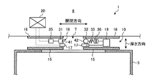
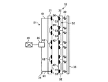
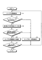
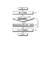
図1は、本実施形態に係るエレベータのドア装置周りを模式的に表した部分平面図である。FIG. 1 is a partial plan view schematically showing the periphery of an elevator door device according to the present embodiment. 図2は、本実施形態に係るエレベータの異物検出装置を示す模式図である。FIG. 2 is a schematic diagram illustrating the elevator foreign matter detection apparatus according to the present embodiment. 図3は、本実施形態に係る第1検出子および第2検出子の外観斜視図である。FIG. 3 is an external perspective view of the first detector and the second detector according to the present embodiment. 図4は、本実施形態に係る隣接する第2検出子を示す模式図である。FIG. 4 is a schematic diagram showing adjacent second detectors according to the present embodiment. 図5は、本実施形態に係るエレベータの閉塞動作を説明するフローチャートである。FIG. 5 is a flowchart for explaining the closing operation of the elevator according to the present embodiment. 図6は、本実施形態に係るエレベータの開放動作を説明するフローチャートである。FIG. 6 is a flowchart illustrating the opening operation of the elevator according to the present embodiment.

〔実施形態〕
図1は、本実施形態に係るエレベータのドア装置周りを模式的に表した部分平面図である。図2は、本実施形態に係るエレベータの異物検出装置を示す模式図である。図3は、本実施形態に係る第1検出子および第2検出子の外観斜視図である。図4は、本実施形態に係る隣接する第2検出子を示す模式図である。図5は、本実施形態に係るエレベータの閉塞動作時における制御の一例を説明するフローチャートである。図6は、本実施形態に係るエレベータの開放動作時における制御の一例を説明するフローチャートである。
Embodiment
FIG. 1 is a partial plan view schematically showing the periphery of an elevator door device according to the present embodiment. FIG. 2 is a schematic diagram illustrating the elevator foreign matter detection apparatus according to the present embodiment. FIG. 3 is an external perspective view of the first detector and the second detector according to the present embodiment. FIG. 4 is a schematic diagram showing adjacent second detectors according to the present embodiment. FIG. 5 is a flowchart for explaining an example of control during the closing operation of the elevator according to the present embodiment. FIG. 6 is a flowchart illustrating an example of control during the opening operation of the elevator according to the present embodiment.

図1に示すように、本実施形態の異物検出装置18を搭載したエレベータ1のドア装置10は、乗りカゴ5と乗り場6との間の出入口7に設けられている。このドア装置10は、カードア(ドア)15と、ホールドア16と、セーフティシュー17と、異物検出装置18と、連動機構19と、ドア制御部20とを含んで構成されている。   As shown in FIG. 1, the door device 10 of the elevator 1 on which the foreign object detection device 18 of the present embodiment is mounted is provided at the entrance 7 between the passenger car 5 and the landing 6. The door device 10 includes a car door (door) 15, a hold door 16, a safety shoe 17, a foreign object detection device 18, an interlocking mechanism 19, and a door control unit 20.

カードア15は、乗りカゴ5側に一対設けられており、一対のカードア15は、両開き式となっている。一対のカードア15は、出入口7の幅方向が開閉方向となっており、特に、開閉方向において、一対のカードア15の閉じる方向が閉塞方向となっており、一対のカードア15の開く方向が開放方向となっている。一対のカードア15は、ドア制御部20によって図示しない動力源が制御されながら、開閉動作を行う。各カードア15は、その閉塞方向における先端面が、カードア15同士が当接し合って閉塞する閉じ合わせ面となっている。   A pair of card doors 15 is provided on the side of the car basket 5, and the pair of card doors 15 is of a double-open type. In the pair of card doors 15, the width direction of the entrance / exit 7 is the opening / closing direction. In particular, in the opening / closing direction, the closing direction of the pair of card doors 15 is the closing direction, and the opening direction of the pair of card doors 15 is the opening direction. It has become. The pair of card doors 15 opens and closes while a power source (not shown) is controlled by the door control unit 20. Each card door 15 has a closed end surface in the closing direction that closes when the card doors 15 come into contact with each other.

ホールドア16は、乗り場6側に一対設けられており、一対のホールドア16は、両開き式となっている。一対のホールドア16は、一対のカードア15にそれぞれ対向させて設けられている。一対のホールドア16は、一対のカードア15と同様に、出入口7の幅方向が開閉方向となっている。一対のホールドア16は、一対のカードア15の開閉動作に連動して、開閉動作を行うように構成されている。   A pair of holders 16 are provided on the landing 6 side, and the pair of holders 16 is of a double-open type. The pair of hold doors 16 are provided to face the pair of card doors 15 respectively. As with the pair of card doors 15, the pair of hold doors 16 has an opening / closing direction in the width direction of the entrance / exit 7. The pair of hold doors 16 are configured to perform an opening / closing operation in conjunction with an opening / closing operation of the pair of card doors 15.

セーフティシュー17は、エレベータ1の出入口7に、障害物が有るか否かを検出するものである。セーフティシュー17は、各カードア15と各ホールドア16との間に設けられ、また、一対のカードア15の閉塞方向の先端部にそれぞれ設けられている。各セーフティシュー17は、閉塞方向において、前進位置と後退位置との間で進退可能となっている。このため、一対のセーフティシュー17は、一対のカードア15が閉塞動作すると、一対のカードア15に先行して移動する。   The safety shoe 17 detects whether there is an obstacle at the entrance 7 of the elevator 1. The safety shoe 17 is provided between each card door 15 and each hold door 16, and is also provided at each end of the pair of card doors 15 in the closing direction. Each safety shoe 17 can be advanced and retracted between the forward position and the backward position in the closing direction. For this reason, the pair of safety shoes 17 moves ahead of the pair of card doors 15 when the pair of card doors 15 is closed.

一対のセーフティシュー17は、一対のカードア15が閉塞動作する場合、それぞれ前進位置にある。一対のセーフティシュー17は、障害物に当たって前進位置から後退位置に移動すると、障害物がある旨の検出信号を、ドア制御部20へ向けて出力する。一方で、一対のセーフティシュー17は、一対のカードア15が閉塞動作する場合、障害物に当たらずに、セーフティシュー17同士が当接する。そして、一対のセーフティシュー17は、一対のカードア15が当接することで、相対的に後退位置に移動すると、障害物がないとして、検出信号をドア制御部20へ向けて出力しない。   The pair of safety shoes 17 are respectively in the forward position when the pair of card doors 15 is closed. When the pair of safety shoes 17 hit the obstacle and move from the forward position to the backward position, the pair of safety shoes 17 outputs a detection signal indicating that there is an obstacle to the door control unit 20. On the other hand, when the pair of safety shoes 17 is closed, the safety shoes 17 abut against each other without hitting an obstacle. When the pair of safety shoes 17 are relatively moved to the retracted position by the contact of the pair of card doors 15, it is determined that there is no obstacle and does not output a detection signal to the door control unit 20.

なお、本実施形態において、カードア15およびホールドア16は、両開き式としたが、片開き式でもよい。この場合、セーフティシュー17は、開閉動作を行う1つのカードア15に設けられる。   In the present embodiment, the card door 15 and the hold door 16 are of double opening type, but may be of single opening type. In this case, the safety shoe 17 is provided in one card door 15 that performs an opening / closing operation.

図1ないし図3に示すように、異物検出装置18は、ヒモやロープ等の細長い異物を検出するものである。異物検出装置18は、第1検出子31と、複数の第2検出子32と、回路部34と、複数の付勢部材33と、支持体36と、通電検出部35と、を含んで構成されている。   As shown in FIGS. 1 to 3, the foreign object detection device 18 detects elongated foreign objects such as strings and ropes. The foreign object detection device 18 includes a first detector 31, a plurality of second detectors 32, a circuit unit 34, a plurality of urging members 33, a support body 36, and an energization detection unit 35. Has been.

第1検出子31は、一対のカードア15の閉じ合わせ面を挟んで一方側(図1の左側)に設けられている。第1検出子31は、カードア15の高さ方向(鉛直方向)に長い長尺物であり、カードア15に取り付けられている。このため、第1検出子31は、固定側の検出子となる。なお、本実施形態では、第1検出子31を固定したが、この構成に限らず、第1検出子31を閉塞方向に進退可能な構成としてもよい。   The first detector 31 is provided on one side (left side in FIG. 1) across the closing surface of the pair of card doors 15. The first detector 31 is a long object that is long in the height direction (vertical direction) of the card door 15, and is attached to the card door 15. For this reason, the first detector 31 is a fixed detector. In the present embodiment, the first detector 31 is fixed. However, the present invention is not limited to this configuration, and the first detector 31 may be configured to advance and retract in the closing direction.

また、第1検出子31は、複数の第2検出子32に対接する第1対接面41を有している。第1対接面41は、第1検出子31の閉塞方向における先端面である。第1対接面41には、カードア15の開閉方向において、外側に没入する凹部43が形成されている。この凹部43は、底面となる平坦面43aと、平坦面43aの両側から外側へ向けて広がるように設けられた一対の第1斜面部43bとから構成され、鉛直方向に直交する水平面において台形状に形成されている。そして、この凹部43は、第1検出子31の長手方向(鉛直方向)に延在して形成されている。なお、本実施形態では、凹部43を台形状に形成したが、この形状に限定されない。つまり、凹部43は、少なくとも第1斜面部43bを有していればよく、例えば、円弧形状に形成してもよい。   The first detector 31 has a first contact surface 41 that contacts the plurality of second detectors 32. The first contact surface 41 is a front end surface of the first detector 31 in the closing direction. The first contact surface 41 is formed with a recess 43 that immerses outside in the opening / closing direction of the card door 15. The recess 43 includes a flat surface 43a serving as a bottom surface and a pair of first slope portions 43b provided so as to spread outward from both sides of the flat surface 43a, and has a trapezoidal shape in a horizontal plane perpendicular to the vertical direction. Is formed. The recess 43 is formed to extend in the longitudinal direction (vertical direction) of the first detector 31. In addition, in this embodiment, although the recessed part 43 was formed in trapezoid shape, it is not limited to this shape. That is, the recessed part 43 should just have the 1st slope part 43b at least, for example, may be formed in circular arc shape.

複数の第2検出子32は、第1検出子31に対向するように、一対のカードア15の閉じ合わせ面を挟んで他方側(図1の右側)に設けられている。複数の第2検出子32は、第1検出子31に沿って、カードア15の高さ方向に並べられている。複数の第2検出子32は、閉塞方向においてそれぞれ進退可能に構成されている。このため、第2検出子32は、可動側の検出子となる。   The plurality of second detectors 32 are provided on the other side (the right side in FIG. 1) across the closing surface of the pair of card doors 15 so as to face the first detector 31. The plurality of second detectors 32 are arranged along the first detector 31 in the height direction of the card door 15. The plurality of second detectors 32 are configured to be able to advance and retract in the closing direction. For this reason, the second detector 32 is a movable detector.

図4に示すように、複数の第2検出子32は、隣接する一方の第2検出子32の一方の端部と、隣接する他方の第2検出子32の他方の端部とが、互いにオーバーラップしている。具体的に、上方側の第2検出子32の下端部は、カードア15の高さ方向において、上側に窪む凹部46を有している。一方で、下方側の第2検出子32の上端部は、カードア15の高さ方向において、上側に突出する凸部47を有している。凹部46および凸部47は、第2検出子32の開閉方向に亘って形成されている。このため、凹部46と凸部47とが合わさることで、隣接する第2検出子32は、凹部46および凸部47をガイドとして、開閉方向における移動がそれぞれ許容される。また、異物が凹部46および凸部47が合わさるオーバーラップ部49に臨んでも、異物は少なくとも凹部46または凸部47に接触することになる。   As shown in FIG. 4, the plurality of second detectors 32 are configured such that one end of one adjacent second detector 32 and the other end of the other adjacent second detector 32 are mutually connected. It overlaps. Specifically, the lower end portion of the upper second detector 32 has a recess 46 that is recessed upward in the height direction of the card door 15. On the other hand, the lower end of the second detector 32 has a convex portion 47 that protrudes upward in the height direction of the card door 15. The concave portion 46 and the convex portion 47 are formed across the opening / closing direction of the second detector 32. For this reason, when the concave portion 46 and the convex portion 47 are combined, the adjacent second detectors 32 are allowed to move in the opening / closing direction using the concave portion 46 and the convex portion 47 as a guide. Further, even if the foreign matter reaches the overlap portion 49 where the concave portion 46 and the convex portion 47 are combined, the foreign matter comes into contact with at least the concave portion 46 or the convex portion 47.

また、各第2検出子32は、第1検出子31の第1対接面41に対接する第2対接面42を有している。第2対接面42は、第2検出子32の閉塞方向における先端面である。第2対接面42には、カードア15の開閉方向において、内側に突出する凸部44が形成されている。この凸部44は、頂面となる平坦面44aと、平坦面44aの両側から内側へ向けて広がるように設けられた一対の第2斜面部44bとから構成され、鉛直方向に直交する水平面において台形状に形成されている。そして、この凸部44は、第2検出子32の長手方向(鉛直方向)に延在して形成されている。なお、本実施形態では、凹部43と同様に、凸部44を台形状に形成したが、この形状に限定されない。つまり、凸部44は、少なくとも第2斜面部44bを有していればよく、例えば、円弧形状に形成してもよい。   Each second detector 32 has a second contact surface 42 that contacts the first contact surface 41 of the first detector 31. The second contact surface 42 is a front end surface of the second detector 32 in the closing direction. The second contact surface 42 is formed with a convex portion 44 that protrudes inward in the opening / closing direction of the card door 15. The convex portion 44 is composed of a flat surface 44a serving as a top surface and a pair of second slope portions 44b provided so as to spread inward from both sides of the flat surface 44a, and in a horizontal plane perpendicular to the vertical direction. It is formed in a trapezoidal shape. The convex portion 44 is formed to extend in the longitudinal direction (vertical direction) of the second detector 32. In the present embodiment, the convex portion 44 is formed in a trapezoidal shape similarly to the concave portion 43, but is not limited to this shape. That is, the convex part 44 should just have the 2nd slope part 44b at least, and may be formed in circular arc shape, for example.

上記の第1対接面41の凹部43と、上記の第2対接面42の凸部44とは、互いに相補的形状となるように形成され、第1対接面41の凹部43は、第2対接面42の凸部44を許容している。   The concave portion 43 of the first contact surface 41 and the convex portion 44 of the second contact surface 42 are formed so as to be complementary to each other, and the concave portion 43 of the first contact surface 41 is The convex portion 44 of the second contact surface 42 is allowed.

回路部34は、第1検出子31と全ての第2検出子32とが対接している状態において、直列回路を形成可能に設けられている。この回路部34は、一対の第1斜面部43bおよび一対の第2斜面部44bに応じて、一対設けられている。なお、以下では、一方の第1斜面部43bおよび一方の第2斜面部44bに設けられた回路部34について説明する。回路部34は、複数の第1電線51と、複数の第2電線52と、複数の第1電極53と、複数の第2電極54と、を含んで構成されている。   The circuit unit 34 is provided so as to form a series circuit in a state where the first detector 31 and all the second detectors 32 are in contact with each other. A pair of the circuit portions 34 is provided according to the pair of first slope portions 43b and the pair of second slope portions 44b. In the following, the circuit portion 34 provided on one first slope portion 43b and one second slope portion 44b will be described. The circuit unit 34 includes a plurality of first electric wires 51, a plurality of second electric wires 52, a plurality of first electrodes 53, and a plurality of second electrodes 54.

図2に示すように、複数の第1電線51は、入力側電線61と、複数の第1湾曲電線62と、出力側電線63とから構成されている。入力側電線61は、第1検出子31の上端部に設けられ、第1検出子31の外部から、第1検出子31の内部を通って、第1検出子31の第1対接面41に至るように配設されている。各第1湾曲電線62は、U字状に形成され、第1検出子31の第1対接面41から、第1検出子31の内部を通って、再び第1検出子31の第1対接面41に至るように配設されている。また、各第1湾曲電線62は、その上端部が、隣接する上方側の第2検出子32の下端部に対向するように配設され、その下端部が、隣接する下方側の第2検出子32の上端部に対向するように配設されている。出力側電線63は、第1検出子31の下端部に設けられ、第1検出子31の第1対接面41から、第1検出子31の内部を通って、第1検出子31の外部に至るように配設されている。   As shown in FIG. 2, the plurality of first electric wires 51 includes an input-side electric wire 61, a plurality of first curved electric wires 62, and an output-side electric wire 63. The input-side electric wire 61 is provided at the upper end of the first detector 31, passes from the outside of the first detector 31 to the inside of the first detector 31, and the first contact surface 41 of the first detector 31. It is arranged to reach. Each first curved electric wire 62 is formed in a U-shape, passes through the inside of the first detector 31 from the first contact surface 41 of the first detector 31, and again returns to the first pair of the first detector 31. It is disposed so as to reach the contact surface 41. In addition, each first curved electric wire 62 is disposed such that the upper end portion thereof faces the lower end portion of the adjacent upper second detector 32, and the lower end portion thereof is adjacent to the lower second detection. It arrange | positions so that the upper end part of the child 32 may be opposed. The output-side electric wire 63 is provided at the lower end portion of the first detector 31 and passes through the inside of the first detector 31 from the first contact surface 41 of the first detector 31 to the outside of the first detector 31. It is arranged to reach.

複数の第2電線52は、複数の第2検出子32にそれぞれ設けられている。各第2電線52は、U字状に形成され、第2検出子32の第2対接面42から、第2検出子32の内部を通って、再び第2検出子32の第2対接面42に至るように配設されている。また、各第2電線52は、その上端部が、第1湾曲電線62の下端部に対向するように配設され、その下端部が、第1湾曲電線62の上端部に対向するように配設されている。なお、鉛直方向の最上側の第2検出子32に設けられた第2電線52は、その上端部が、入力側電線61に対向するように配設されている。また、鉛直方向の最下側の第2検出子32に設けられた第2電線52は、その下端部が、出力側電線63に対向するように配設されている。   The plurality of second electric wires 52 are respectively provided on the plurality of second detectors 32. Each of the second electric wires 52 is formed in a U-shape, passes through the inside of the second detector 32 from the second contact surface 42 of the second detector 32, and again returns to the second contact of the second detector 32. Arranged to reach the surface 42. Further, each second electric wire 52 is arranged so that the upper end portion thereof faces the lower end portion of the first curved electric wire 62, and the lower end portion thereof is arranged so as to face the upper end portion of the first curved electric wire 62. It is installed. The second electric wire 52 provided in the second detector 32 on the uppermost side in the vertical direction is arranged so that the upper end portion thereof faces the input-side electric wire 61. Further, the second electric wire 52 provided in the second detector 32 on the lowermost side in the vertical direction is arranged so that the lower end portion thereof faces the output-side electric wire 63.

複数の第1電極53は、第1検出子31の第1対接面41における第1斜面部43bにそれぞれ設けられている。複数の第1電極53は、入力側電線61、複数の第1湾曲電線62および出力側電線63にそれぞれ接続されている。つまり、複数の第1電極53のうち、その鉛直方向の最上側の第1電極53は、入力側電線61の第1対接面41側の端部に接続されて、第1斜面部43bの鉛直方向の最上側に配設されている。また、複数の第1電極53のうち、その鉛直方向の最下側の第1電極53は、出力側電線63の第1対接面41側の端部に接続されて、第1斜面部43bの鉛直方向の最下側に配設されている。また、その他の第1電極53は、第1湾曲電線62の両端部にそれぞれ接続されて、第1斜面部43bに配設されている。なお、本実施形態では、第1湾曲電線62の両端部に第1電極53をそれぞれ接続したが、第1湾曲電線62を省き、第1湾曲電線62の両端部の第1電極53同士を接続してもよい。   The plurality of first electrodes 53 are respectively provided on the first slope portion 43 b of the first contact surface 41 of the first detector 31. The plurality of first electrodes 53 are connected to the input side electric wires 61, the plurality of first curved electric wires 62, and the output side electric wires 63, respectively. That is, among the plurality of first electrodes 53, the first electrode 53 on the uppermost side in the vertical direction is connected to the end portion on the first contact surface 41 side of the input-side electric wire 61, and the first inclined surface portion 43b. It is arranged on the uppermost side in the vertical direction. In addition, among the plurality of first electrodes 53, the first electrode 53 on the lowermost side in the vertical direction is connected to the end portion on the first contact surface 41 side of the output-side electric wire 63, and the first inclined surface portion 43b. Is disposed on the lowermost side in the vertical direction. Further, the other first electrodes 53 are respectively connected to both end portions of the first curved electric wire 62 and disposed on the first inclined surface portion 43b. In the present embodiment, the first electrodes 53 are connected to both ends of the first curved wire 62. However, the first curved wires 62 are omitted and the first electrodes 53 at both ends of the first curved wire 62 are connected to each other. May be.

複数の第2電極54は、複数の第1電極53に対向するように設けられ、複数の第2検出子32の第2対接面42における第2斜面部44bにそれぞれ設けられている。複数の第2電極54は、第2電線52に接続されている。つまり、複数の第2電極54は、各第2電線52の両端部にそれぞれ接続されて、第2斜面部44bに配設されている。   The plurality of second electrodes 54 are provided so as to face the plurality of first electrodes 53, and are respectively provided on the second inclined surfaces 44 b on the second contact surfaces 42 of the plurality of second detectors 32. The plurality of second electrodes 54 are connected to the second electric wire 52. That is, the plurality of second electrodes 54 are connected to both end portions of each second electric wire 52 and disposed on the second inclined surface portion 44b.

このように構成された回路部43は、第1検出子31に全ての第2検出子32が対接すると、複数の第1電極53と複数の第2電極54とが接触する。これにより、回路部34は、入力側電線61と第2電線52とが接続され、第2電線52と第1湾曲電線62とが接続され、第1湾曲電線62と第2電線52とが接続され、第1湾曲電線62と第2電線52との接続が繰り返され、第2電線52と出力側電線63とが接続される。つまり、回路部34は、複数の第1電線53および複数の第2電線54が直列に接続されることで、直列回路となる。そして、回路部34が直列回路となることで、回路部34は通電可能な状態となる。   In the circuit unit 43 configured as described above, when all the second detectors 32 are in contact with the first detector 31, the plurality of first electrodes 53 and the plurality of second electrodes 54 are in contact with each other. Thereby, as for the circuit part 34, the input side electric wire 61 and the 2nd electric wire 52 are connected, the 2nd electric wire 52 and the 1st curved electric wire 62 are connected, and the 1st curved electric wire 62 and the 2nd electric wire 52 are connected. Then, the connection between the first curved electric wire 62 and the second electric wire 52 is repeated, and the second electric wire 52 and the output-side electric wire 63 are connected. That is, the circuit unit 34 becomes a series circuit by connecting the plurality of first electric wires 53 and the plurality of second electric wires 54 in series. And the circuit part 34 will be in the state which can supply with electricity because the circuit part 34 becomes a series circuit.

支持体36は、複数の第2検出子32を、下記する複数の付勢部材33を介して支持している。支持体36は、鉛直方向に長い長尺物であり、カードア15に対し、閉塞方向に進退可能に取り付けられている。つまり、支持体36は、閉塞方向において、前進位置と後退位置との間で移動する。この支持体36は、セーフティシュー17の進退動作に連動して進退動作する。   The support 36 supports the plurality of second detectors 32 via a plurality of biasing members 33 described below. The support 36 is a long object that is long in the vertical direction, and is attached to the card door 15 so as to be able to advance and retreat in the closing direction. That is, the support body 36 moves between the forward movement position and the backward movement position in the closing direction. The support 36 moves back and forth in conjunction with the movement of the safety shoe 17.

複数の付勢部材33は、複数の第2検出子32と支持体36との間に介設されており、複数の第2検出子32を弾性支持している。複数の付勢部材33は、複数の第2検出子32を第1検出子31へ向けて付勢している。付勢部材33は、各第2検出子32の上端側および下端側にそれぞれ設けられている。   The plurality of urging members 33 are interposed between the plurality of second detectors 32 and the support 36 and elastically support the plurality of second detectors 32. The plurality of urging members 33 urge the plurality of second detectors 32 toward the first detector 31. The urging member 33 is provided on each of the upper end side and the lower end side of each second detector 32.

通電検出部35は、回路部34が通電状態(直列回路)となっているか否か、つまり、第1検出子31に全ての第2検出子32が対接しているか否かを検出するものである。通電検出部35には、入力側電線61と出力側電線63とが接続されており、通電検出部35は、入力側電線61へ向けて電気信号を出力可能となっている。そして、通電検出部35は、入力側電線61へ向けて電気信号を出力し、出力側電線63から電気信号が入力されないと、回路部34が通電状態でないとして、細長い異物が挟み込まれている旨の異常検出信号をドア制御部20へ向けて出力する。一方で、通電検出部35は、入力側電線61へ向けて電気信号を出力し、出力側電線63から電気信号が入力されると、回路部34が通電状態であるとして、異常検出信号をドア制御部20へ向けて出力しない。   The energization detection unit 35 detects whether or not the circuit unit 34 is in an energized state (series circuit), that is, whether or not all the second detectors 32 are in contact with the first detector 31. is there. An input side electric wire 61 and an output side electric wire 63 are connected to the energization detection unit 35, and the energization detection unit 35 can output an electric signal toward the input side electric wire 61. And the energization detection part 35 outputs an electrical signal toward the input side electric wire 61, and if an electric signal is not input from the output side electric wire 63, the circuit part 34 will not be in an energized state, and that the elongate foreign object is pinched | interposed Is output to the door control unit 20. On the other hand, the energization detection unit 35 outputs an electric signal toward the input side electric wire 61, and when an electric signal is input from the output side electric wire 63, the circuit unit 34 is in an energized state, and the abnormality detection signal is output to the door. It does not output to the control unit 20.

連動機構19は、セーフティシュー17の進退動作に連動させて、支持体36および複数の付勢部材33を介して、複数の第2検出子32を進退動作させるものである。なお、連動機構19は、例えば、リンク機構を用いて構成されているが、この構成に限定されず、カム機構またはラック・アンド・ピニオン等を用いて構成してもよい。連動機構19は、セーフティシュー17が閉塞方向において後退位置に移動すると、異物検出装置18の支持体36を閉塞方向の前進位置へ移動させることにより、複数の第2検出子32を第1検出子31へ対接させる。一方で、連動機構19は、セーフティシュー17が閉塞方向において前進位置に移動すると、異物検出装置18の支持体36を閉塞方向の後退位置へ移動させることにより、複数の第2検出子32を第1検出子31から離す。   The interlocking mechanism 19 is configured to cause the plurality of second detectors 32 to advance and retract via the support 36 and the plurality of urging members 33 in conjunction with the advance and retreat operation of the safety shoe 17. The interlocking mechanism 19 is configured using, for example, a link mechanism, but is not limited to this configuration, and may be configured using a cam mechanism, a rack and pinion, or the like. When the safety shoe 17 moves to the retracted position in the closing direction, the interlocking mechanism 19 moves the support 36 of the foreign object detection device 18 to the advanced position in the closing direction, thereby moving the plurality of second detectors 32 to the first detector. It is made to contact 31. On the other hand, when the safety shoe 17 moves to the advanced position in the closing direction, the interlocking mechanism 19 moves the support 36 of the foreign object detection device 18 to the retracted position in the closing direction, thereby moving the plurality of second detectors 32 to the first position. 1 away from the detector 31.

ドア制御部20は、図示しない動力源を制御して、カードア15の開閉動作を制御している。具体的に、ドア制御部20は、カードア15の閉塞動作時において、セーフティシュー17から出力された検出信号が入力されると、カードア15の閉塞動作から、カードア15の開放動作へ切り換える。また、ドア制御部20は、カードア15の閉塞動作時において、異物検出装置18の通電検出部35から出力された異物検出信号が入力されると、カードア15の閉塞動作から、カードア15の開放動作へ切り換える。   The door control unit 20 controls the opening / closing operation of the card door 15 by controlling a power source (not shown). Specifically, when the detection signal output from the safety shoe 17 is input during the closing operation of the card door 15, the door control unit 20 switches from the closing operation of the card door 15 to the opening operation of the card door 15. Further, when the foreign object detection signal output from the energization detection unit 35 of the foreign object detection device 18 is input during the closing operation of the card door 15, the door control unit 20 starts the opening operation of the card door 15 from the closing operation of the card door 15. Switch to.

続いて、図5を参照し、一対のカードア15の閉塞動作に関する一連の動作フローについて説明する。先ず、ドア制御部20は、動力源を制御して、一対のカードア15を閉塞動作させる(ステップS1)。すると、一対のホールドア16は、一対のカードア15の閉塞動作に連動して閉塞動作を行う。このとき、一対のカードア15の閉塞方向の先端部に設けた一対のセーフティシュー17は、エレベータ1の出入口7に障害物が有るか否かを検出する(ステップS2)。   Next, a series of operation flows related to the closing operation of the pair of card doors 15 will be described with reference to FIG. First, the door control unit 20 controls the power source to cause the pair of card doors 15 to close (step S1). Then, the pair of hold doors 16 performs a closing operation in conjunction with the closing operation of the pair of card doors 15. At this time, the pair of safety shoes 17 provided at the front ends of the pair of card doors 15 in the closing direction detects whether or not there is an obstacle at the entrance 7 of the elevator 1 (step S2).

ドア制御部20は、一対のセーフティシュー17により検出信号が入力される(ステップS2:Yes)と、一対のカードア15を一時的に開放動作させ(ステップS3)、この後、再度ステップS1に進んで、カードア15を閉塞動作させる。一方で、ドア制御部20は、一対のセーフティシュー17により検出信号が入力されず(ステップS2:No)、一対のセーフティシュー17同士が当接して後退位置に移動する。すると、図示右側のセーフティシュー17の移動により、連動機構19を介して、支持体36、複数の付勢部材33および複数の第2検出子32が一体に前進位置へ移動し、これにより、複数の第2検出子32を第1検出子31へ対接させる(ステップS4)。   When the detection signal is input by the pair of safety shoes 17 (step S2: Yes), the door control unit 20 temporarily opens the pair of card doors 15 (step S3), and then proceeds to step S1 again. Thus, the card door 15 is closed. On the other hand, the door control unit 20 does not receive a detection signal from the pair of safety shoes 17 (step S2: No), and the pair of safety shoes 17 come into contact with each other and move to the retracted position. Then, by movement of the safety shoe 17 on the right side of the figure, the support body 36, the plurality of urging members 33, and the plurality of second detectors 32 are integrally moved to the advance position via the interlocking mechanism 19, thereby The second detector 32 is brought into contact with the first detector 31 (step S4).

複数の第2検出子32を第1検出子31へ対接させると、第1検出子31の第1対接面41における凹部43に、各第2検出子32の第2対接面42における凸部44が合わさる。このとき、第1対接面41の第1斜面部43bに設けられた第1電極53と、第2対接面42の第2斜面部44bに設けられた第2電極54とは、カードア15の閉塞方向に対して斜めに対接する。これにより、第1電極53と第2電極54とは、擦れ合って接触する。また、複数の第2検出子32は、オーバーラップ部49において、上方側の第2検出子32の凹部46と、下方側の第2検出子32の凸部47とが合わさっているため、各第2検出子32は、凹部46および凸部47をガイドとして、開閉方向に個別に移動する。   When the plurality of second detectors 32 are brought into contact with the first detector 31, the recesses 43 in the first contact surface 41 of the first detector 31 are brought into contact with the second contact surfaces 42 of the second detectors 32. The convex portions 44 are combined. At this time, the first electrode 53 provided on the first slope portion 43b of the first contact surface 41 and the second electrode 54 provided on the second slope portion 44b of the second contact surface 42 are the same as the car door 15. It contacts diagonally with respect to the closing direction. Thereby, the 1st electrode 53 and the 2nd electrode 54 are rubbed and contacted. Further, since the plurality of second detectors 32 are overlapped with the concave portion 46 of the upper second detector 32 and the convex portion 47 of the lower second detector 32 in the overlap portion 49, The second detector 32 moves individually in the opening and closing direction using the concave portion 46 and the convex portion 47 as a guide.

そして、複数の第2検出子32を第1検出子31へ対接させた後、ドア制御部20は、通電検出部35から回路部34の入力側電線61へ電気信号を出力することで、異常検出信号があるか否かを判定する(ステップS5)。この後、通電検出部35は、回路部34の出力側電線63から電気信号が入力されないと、回路部34が通電状態でないとして、異常検出信号をドア制御部20へ出力する(ステップS5:Yes)。ドア制御部20は、異物検出装置18により異常検出信号が入力されると、カードア15を一時的に開放動作させ(ステップS3)、この後、再度ステップS1に進んで、カードア15を閉塞動作させる。   Then, after bringing the plurality of second detectors 32 into contact with the first detector 31, the door control unit 20 outputs an electrical signal from the energization detection unit 35 to the input-side electric wire 61 of the circuit unit 34. It is determined whether or not there is an abnormality detection signal (step S5). Thereafter, when an electrical signal is not input from the output-side electric wire 63 of the circuit unit 34, the energization detection unit 35 outputs an abnormality detection signal to the door control unit 20 assuming that the circuit unit 34 is not energized (step S5: Yes). ). When an abnormality detection signal is input from the foreign object detection device 18, the door control unit 20 temporarily opens the card door 15 (step S3), and then proceeds to step S1 again to close the card door 15. .

一方で、通電検出部35は、回路部34の出力側電線63から電気信号が入力されると、回路部34が通電状態であるとして、異常検出信号をドア制御部20へ出力しない(ステップS5:No)。ドア制御部20は、異物検出装置18により異常検出信号が入力されないため、カードア15の閉塞動作を継続する(ステップS6)。   On the other hand, when an electrical signal is input from the output-side electric wire 63 of the circuit unit 34, the energization detection unit 35 assumes that the circuit unit 34 is in an energized state and does not output an abnormality detection signal to the door control unit 20 (step S5). : No). The door control unit 20 continues the closing operation of the card door 15 because no abnormality detection signal is input by the foreign object detection device 18 (step S6).

そして、ドア制御部20は、カードア15の閉塞動作が終了したか否かを検出し(ステップS7)、閉塞動作が終了したことを検出したら(ステップS7:Yes)、一対のカードア15の閉塞動作を終了する。一方で、ドア制御部20は、閉塞動作が終了していないことを検出したら(ステップS7:No)、再度ステップS1に進み、カードア15に閉塞動作を行わせる。   Then, the door control unit 20 detects whether or not the closing operation of the card door 15 has been completed (step S7), and when detecting that the closing operation has ended (step S7: Yes), the door closing operation of the pair of card doors 15 is performed. Exit. On the other hand, when the door control unit 20 detects that the closing operation has not ended (step S7: No), the door control unit 20 proceeds to step S1 again and causes the card door 15 to perform the closing operation.

次に、図6を参照し、一対のカードア15の開放動作時における異物検出装置18の一連の動作フローについて説明する。先ず、エレベータ1の乗りカゴ5が所定の乗り場6に着床する(ステップS11)と、ドア制御部20は、通電検出部35から回路部34の入力側電線61へ電気信号を出力することで、異常検出信号があるか否かを判定する(ステップS12)。   Next, with reference to FIG. 6, a series of operation flows of the foreign object detection device 18 during the opening operation of the pair of card doors 15 will be described. First, when the elevator car 5 of the elevator 1 reaches the predetermined landing 6 (step S11), the door control unit 20 outputs an electrical signal from the energization detection unit 35 to the input-side electric wire 61 of the circuit unit 34. Then, it is determined whether there is an abnormality detection signal (step S12).

通電検出部35は、回路部34の出力側電線63から電気信号が入力されないと、回路部34が通電状態でないとして、異常検出信号をドア制御部20へ出力する(ステップS12:Yes)。すると、ドア制御部20は、異物検出装置18の故障であると判断し、エレベータ1を管理する管理会社へ、異物検出装置18の故障である旨の通報を行う(ステップS13)。そして、ドア制御部20は、ステップS13の後、一対のカードア15を開放動作させる(ステップS14)。   If an electric signal is not input from the output-side electric wire 63 of the circuit unit 34, the energization detection unit 35 outputs an abnormality detection signal to the door control unit 20 assuming that the circuit unit 34 is not in an energized state (step S12: Yes). Then, the door control unit 20 determines that the foreign object detection device 18 is out of order, and notifies the management company that manages the elevator 1 that the foreign object detection device 18 is out of order (step S13). Then, after step S13, the door control unit 20 opens the pair of card doors 15 (step S14).

一方で、ステップS12において、通電検出部35は、回路部34の出力側電線63から電気信号が入力されると、回路部34が通電状態であるとして、異常検出信号をドア制御部20へ出力しない(ステップS12:No)。そして、ドア制御部20は、ステップS13を行わず、一対のカードア15を開放動作させる(ステップS14)。   On the other hand, in step S <b> 12, when an electrical signal is input from the output-side electric wire 63 of the circuit unit 34, the energization detection unit 35 outputs an abnormality detection signal to the door control unit 20 assuming that the circuit unit 34 is in an energized state. No (Step S12: No). Then, the door control unit 20 does not perform step S13, but opens the pair of card doors 15 (step S14).

以上のように、本実施形態の構成によれば、複数の第2検出子32を第1検出子31に沿って並べて設けたため、各第2検出子32の長さを、第1検出子31に比して短くすることができる。このため、第2検出子32は、その長さが短くなったことで撓み難くなる。これにより、第1検出子31と第2検出子32との間に、細長い異物が挟まった場合でも、第2検出子32が撓み難いため、第1検出子31と第2検出子32との間の隙間を、好適に維持することができる。よって、異物検出装置18は、細長い異物が挟まった場合、異物の検出を精度よく行うことが可能となる。   As described above, according to the configuration of the present embodiment, since the plurality of second detectors 32 are arranged along the first detector 31, the length of each second detector 32 is set to the first detector 31. It can be shortened compared to. For this reason, the 2nd detector 32 becomes difficult to bend because the length became short. As a result, even when an elongated foreign object is sandwiched between the first detector 31 and the second detector 32, the second detector 32 is difficult to bend. Therefore, the first detector 31 and the second detector 32 are not bent. The gap between them can be suitably maintained. Therefore, the foreign object detection device 18 can detect the foreign object with high accuracy when an elongated foreign object is caught.

また、本実施形態の構成によれば、第1対接面41に凹部43を設け、第2対接面42に凸部44を設けると共に、互いに相補的形状となる凹部43および凸部44を形成することができる。このため、第1対接面41および第2対接面42の間に細長い異物が挟み込まれると、細長い異物は、第1対接面41の凹部43における平坦面43aとの間に隙間が生じた状態で、第2対接面42の凸部44に挟み込まれる。これにより、第1対接面41および第2対接面42の間には、隙間が形成され易くなり、異物検出装置18は、細長い異物の検出をより精度よく行うことができる。   Further, according to the configuration of the present embodiment, the concave portion 43 is provided on the first contact surface 41, the convex portion 44 is provided on the second contact surface 42, and the concave portion 43 and the convex portion 44 that are complementary to each other are provided. Can be formed. For this reason, when an elongated foreign object is sandwiched between the first contact surface 41 and the second contact surface 42, a gap is generated between the elongated foreign object and the flat surface 43 a in the concave portion 43 of the first contact surface 41. In this state, it is sandwiched between the convex portions 44 of the second contact surface 42. Thereby, it becomes easy to form a clearance gap between the 1st contact surface 41 and the 2nd contact surface 42, and the foreign material detection apparatus 18 can detect an elongate foreign material more accurately.

また、本実施形態の構成によれば、第1電極53を第1斜面部43bに設け、第2電極54を第2斜面部44bに設けることができる。このため、カードア15の閉塞方向に対し、第1電極53と第2電極54とが斜めに対接し、第1電極53と第2電極54とが擦れ合い易くなる。これにより、第1電極53および第2電極54の表面に酸化皮膜が形成されても、第1電極53と第2電極54とが擦れ合うことで、形成される酸化皮膜を擦り落すことができるため、異物検出装置18は、検出精度を好適に維持することができる。   Further, according to the configuration of the present embodiment, the first electrode 53 can be provided on the first slope portion 43b, and the second electrode 54 can be provided on the second slope portion 44b. For this reason, the first electrode 53 and the second electrode 54 contact each other obliquely with respect to the closing direction of the card door 15, and the first electrode 53 and the second electrode 54 are easily rubbed. Thereby, even if an oxide film is formed on the surfaces of the first electrode 53 and the second electrode 54, the formed oxide film can be scraped off by the friction between the first electrode 53 and the second electrode 54. The foreign object detection device 18 can preferably maintain the detection accuracy.

また、本実施形態の構成によれば、上方側の第2検出子32の下端部と、下方側の第2検出子32の上端部とを互いにオーバーラップさせることができる。このため、第1検出子31と隣接する第2検出子32のオーバーラップ部49との間に、細長い異物が挟み込まれたとしても、異物を、第1検出子31と、上方側の第2検出子32または下方側の第2検出子32のいずれか一方との間に挟み込むことができる。これにより、異物が上方側の第2検出子32と下方側の第2検出子32との間に挟み込まれることがないため、異物検出装置18は、異物を第1検出子31および各第2検出子32の間に好適に挟み込むことができる。   Further, according to the configuration of the present embodiment, the lower end portion of the upper second detector 32 and the upper end portion of the lower second detector 32 can be overlapped with each other. For this reason, even if an elongated foreign object is sandwiched between the first detector 31 and the overlapping portion 49 of the adjacent second detector 32, the foreign object is separated from the first detector 31 and the upper second side. It can be sandwiched between either the detector 32 or the lower second detector 32. Accordingly, since the foreign matter is not sandwiched between the upper second detector 32 and the lower second detector 32, the foreign matter detection device 18 detects the foreign matter as the first detector 31 and each second detector. It can be suitably sandwiched between the detectors 32.

また、本実施形態の構成によれば、セーフティシュー17の進退動作に連動して複数の第2検出子32を進退動作させる連動機構19を設けることができる。このため、ドア装置10は、セーフティシュー17による障害物の検出を行い、カードア15を閉塞動作させた後、異物検出装置18による細長い異物の検出を行うことができる。これにより、第1検出子31および複数の第2検出子32は、カードア15が開放した状態で異物の検出を行うことがないため、第1電極53および第2電極54が外部に露出し難く、第1電極53および第2電極54を保護しながら使用することができる。   Further, according to the configuration of the present embodiment, it is possible to provide the interlocking mechanism 19 that causes the plurality of second detectors 32 to advance and retract in conjunction with the advance and retract operation of the safety shoe 17. For this reason, the door device 10 can detect an obstruction by the safety shoe 17 and can detect the elongated foreign matter by the foreign matter detection device 18 after closing the card door 15. As a result, the first detector 31 and the plurality of second detectors 32 do not detect foreign matter in a state where the card door 15 is open, so that the first electrode 53 and the second electrode 54 are not easily exposed to the outside. The first electrode 53 and the second electrode 54 can be used while being protected.

また、本実施形態の構成によれば、カードア15が開放動作を行う前に、通電検出部35により回路部34が通電状態であるか否かを検出することができる。このため、異物検出装置18が正常であれば、第1検出子31と全ての第2検出子32が対接しているため、通電検出部35は、異常検出信号をドア制御部20へ向けて出力しない。一方で、通電検出部35は、第1検出子31と全ての第2検出子32が対接していても、異常検出信号をドア制御部20へ向けて出力する場合、異物検出装置18の異常として検出することができる。このため、ドア制御部20は、異物検出装置18の異常を好適に発見することができる。   Further, according to the configuration of the present embodiment, it is possible to detect whether the circuit unit 34 is in the energized state by the energization detection unit 35 before the card door 15 performs the opening operation. For this reason, if the foreign object detection device 18 is normal, the first detector 31 and all the second detectors 32 are in contact with each other, so that the energization detector 35 sends an abnormality detection signal to the door controller 20. Do not output. On the other hand, even if the first detector 31 and all the second detectors 32 are in contact with each other, the energization detection unit 35 outputs an abnormality detection signal toward the door control unit 20, and thus the abnormality of the foreign object detection device 18 is detected. Can be detected as For this reason, the door control part 20 can discover the abnormality of the foreign material detection apparatus 18 suitably.

なお、本実施形態は、例として提示したものであり、発明の範囲を限定することは意図していない。本実施形態は、その他の様々な形態で実施されることが可能であり、発明の要旨を逸脱しない範囲で、種々の省略、置き換え、変更を行うことができる。本実施形態やその変形は、発明の範囲や要旨に含まれると同様に、特許請求の範囲に記載された発明とその均等の範囲に含まれるものである。   This embodiment is presented as an example and is not intended to limit the scope of the invention. The present embodiment can be implemented in various other forms, and various omissions, replacements, and changes can be made without departing from the spirit of the invention. This embodiment and its modifications are included in the scope of the present invention and the gist thereof, and are also included in the invention described in the claims and the equivalents thereof.

1 エレベータ
5 乗りカゴ
6 乗り場
7 出入口
10 ドア装置
15 カードア
16 ホールドア
17 セーフティシュー
18 異物検出装置
19 連動機構
20 ドア制御部
31 第1検出子
32 第2検出子
33 付勢部材
34 回路部
35 通電検出部
36 支持体
41 第1対接面
42 第2対接面
43 第1対接面の凹部
43b 第1斜面部
44 第2対接面の凸部
44b 第2斜面部
46 第2検出子の凹部
47 第2検出子の凸部
49 オーバーラップ部
51 第1電線
52 第2電線
53 第1電極
54 第2電極
DESCRIPTION OF SYMBOLS 1 Elevator 5 Riding basket 6 Platform 7 Entrance / exit 10 Door device 15 Card door 16 Hold door 17 Safety shoe 18 Foreign object detection device 19 Interlock mechanism 20 Door control part 31 1st detection element 32 2nd detection element 33 Energizing member 34 Circuit part 35 Current supply Detection unit 36 Support body 41 First contact surface 42 Second contact surface 43 Concave portion of first contact surface 43b First slope portion 44 Convex portion of second contact surface 44b Second slope portion 46 of second detector Concave portion 47 Convex portion of second detector 49 Overlap portion 51 First electric wire 52 Second electric wire 53 First electrode 54 Second electrode

Claims (6)

エレベータの乗りカゴの出入口を開閉するドアの閉じ合わせ面を挟んで一方側に設けられた第1検出子と、
前記第1検出子に対向するように、前記ドアの閉じ合わせ面を挟んで他方側に設けられ、前記第1検出子に沿って並べた複数の第2検出子と、
前記複数の第2検出子を前記第1検出子側へ向けてそれぞれ付勢する複数の付勢部材と、
前記ドアの閉塞時に前記第1検出子に全ての前記第2検出子が対接することにより通電可能となる回路部と、
前記ドアの閉塞時に前記回路部が通電状態であるか否かを検出可能な通電検出部と、を備えたことを特徴とする異物検出装置。
A first detector provided on one side across a closing surface of a door that opens and closes an entrance / exit of an elevator car;
A plurality of second detectors arranged on the other side across the closing surface of the door so as to face the first detector, and arranged along the first detector;
A plurality of biasing members for biasing the plurality of second detectors toward the first detector;
A circuit part that can be energized when all the second detectors are in contact with the first detectors when the door is closed;
A foreign matter detection apparatus comprising: an energization detection unit capable of detecting whether or not the circuit unit is energized when the door is closed.
前記第1検出子は、前記第2検出子に対接する第1対接面を有し、
前記第2検出子は、前記第1対接面に対接する第2対接面を有し、
前記第1対接面および前記第2対接面は、その一方の対接面が前記ドアの開閉方向に突出する凸部を有し、その他方の対接面が前記ドアの開閉方向に没入し、前記凸部を許容する凹部を有していることを特徴とする請求項1に記載の異物検出装置。
The first detector has a first contact surface that contacts the second detector;
The second detector has a second contact surface that contacts the first contact surface;
The first contact surface and the second contact surface have a convex portion with one contact surface protruding in the door opening / closing direction, and the other contact surface is immersed in the door opening / closing direction. The foreign matter detecting device according to claim 1, further comprising a concave portion that allows the convex portion.
前記回路部は、前記第1検出子に設けられた複数の第1電極と、前記各第1電極に接触可能に、前記複数の第2検出子にそれぞれ設けられた複数の第2電極と、を有し、前記複数の第1電極に対し、前記複数の第2電極が全て対接することで、通電可能となっており、
前記第1対接面は、前記ドアが閉じる閉塞方向に対して傾斜する第1斜面部を有し、
前記第2対接面は、前記第1斜面部に対接する第2斜面部を有し、
前記複数の第1電極は、前記第1斜面部に設けられ、前記複数の第2電極は、前記第2斜面部に設けられていることを特徴とする請求項2に記載の異物検出装置。
The circuit unit includes a plurality of first electrodes provided on the first detector, a plurality of second electrodes provided on the plurality of second detectors so as to be in contact with the first electrodes, The plurality of second electrodes are all in contact with the plurality of first electrodes, and can be energized.
The first contact surface has a first inclined surface portion inclined with respect to a closing direction in which the door is closed,
The second contact surface has a second inclined surface portion that contacts the first inclined surface portion,
The foreign object detection device according to claim 2, wherein the plurality of first electrodes are provided on the first slope portion, and the plurality of second electrodes are provided on the second slope portion.
前記複数の第2検出子は、隣接する一方の前記第2検出子の一方の端部と、隣接する他方の前記第2検出子の他方の端部とが、互いにオーバーラップしていることを特徴とする請求項1ないし3のいずれか1項に記載の異物検出装置。   In the plurality of second detectors, one end portion of one adjacent second detector and the other end portion of the other adjacent second detector overlap each other. The foreign matter detection device according to claim 1, wherein the foreign matter detection device is characterized in that: 前記エレベータの乗りカゴの出入口を開閉可能な前記ドアと、
前記ドアの閉塞方向の先端部に進退可能に設けられ、障害物の接触により後退動作することで、前記障害物を検出可能なセーフティシューと、
請求項1ないし4のいずれか1項に記載の異物検出装置と、
前記セーフティシューの後退動作に連動して、前記異物検出装置の前記複数の第2検出子を前記第1検出子へ向けて移動させる連動機構と、
前記ドアの開閉動作を制御可能なドア制御部と、を備えたエレベータのドア装置。
The door capable of opening and closing the entrance of the elevator car;
A safety shoe capable of detecting the obstacle by moving backward and forward by contact with the obstacle, provided to be able to move forward and backward at the front end in the closing direction of the door;
The foreign object detection device according to any one of claims 1 to 4,
An interlocking mechanism for moving the plurality of second detectors of the foreign object detection device toward the first detector in conjunction with the backward movement of the safety shoe;
An elevator door device comprising: a door control unit capable of controlling an opening / closing operation of the door.
前記ドア制御部は、前記ドアの開放動作前に前記回路部へ通電し、前記異物検出装置の前記通電検出部が、前記回路部が非通電状態であることを検出した場合、前記異物検出装置の故障であると判定することを特徴とする請求項5に記載のエレベータのドア装置。   When the door control unit energizes the circuit unit before the door opening operation, and the energization detection unit of the foreign object detection device detects that the circuit unit is in a non-energized state, the foreign object detection device The elevator door device according to claim 5, wherein the elevator door device is determined to be a malfunction.
JP2011064338A 2011-03-23 2011-03-23 Foreign material detecting device and door device for elevator Withdrawn JP2012201418A (en)

Priority Applications (1)

Application Number Priority Date Filing Date Title
JP2011064338A JP2012201418A (en) 2011-03-23 2011-03-23 Foreign material detecting device and door device for elevator

Applications Claiming Priority (1)

Application Number Priority Date Filing Date Title
JP2011064338A JP2012201418A (en) 2011-03-23 2011-03-23 Foreign material detecting device and door device for elevator

Publications (1)

Publication Number Publication Date
JP2012201418A true JP2012201418A (en) 2012-10-22

Family

ID=47182806

Family Applications (1)

Application Number Title Priority Date Filing Date
JP2011064338A Withdrawn JP2012201418A (en) 2011-03-23 2011-03-23 Foreign material detecting device and door device for elevator

Country Status (1)

Country Link
JP (1) JP2012201418A (en)

Cited By (5)

* Cited by examiner, † Cited by third party
Publication number Priority date Publication date Assignee Title
CN103508300A (en) * 2013-09-24 2014-01-15 日立电梯(中国)有限公司 Elevator safety touch panel system, elevator car door system and elevator car door system control method
CN109693993A (en) * 2017-10-24 2019-04-30 平山工程公司 Elevator cab door anti-pinch sensor device
WO2020003448A1 (en) * 2018-06-28 2020-01-02 三菱電機株式会社 Door device
CN114074888A (en) * 2020-08-14 2022-02-22 蒋洋 Elevator door leaf lower end clearance control mechanism
CN115838106A (en) * 2023-01-06 2023-03-24 广东卓梅尼技术股份有限公司 A car door anti-pinch system for an elevator car

Cited By (8)

* Cited by examiner, † Cited by third party
Publication number Priority date Publication date Assignee Title
CN103508300A (en) * 2013-09-24 2014-01-15 日立电梯(中国)有限公司 Elevator safety touch panel system, elevator car door system and elevator car door system control method
CN109693993A (en) * 2017-10-24 2019-04-30 平山工程公司 Elevator cab door anti-pinch sensor device
WO2020003448A1 (en) * 2018-06-28 2020-01-02 三菱電機株式会社 Door device
JPWO2020003448A1 (en) * 2018-06-28 2020-12-17 三菱電機株式会社 Door device
CN112334405A (en) * 2018-06-28 2021-02-05 三菱电机株式会社 door device
CN112334405B (en) * 2018-06-28 2022-09-02 三菱电机株式会社 Door device
CN114074888A (en) * 2020-08-14 2022-02-22 蒋洋 Elevator door leaf lower end clearance control mechanism
CN115838106A (en) * 2023-01-06 2023-03-24 广东卓梅尼技术股份有限公司 A car door anti-pinch system for an elevator car

Similar Documents

Publication Publication Date Title
JP2012201418A (en) Foreign material detecting device and door device for elevator
EP2347987B1 (en) Elevator safety device
US20170066625A1 (en) Elevator position detection apparatus
JPWO2005115899A1 (en) Rail joint detection device for elevator and elevator device
JP2016166064A (en) Elevator and sill closing device for elevator
JP2009051615A (en) Elevator device
JP5763728B2 (en) Electromagnetic switchgear
JP6579267B2 (en) Elevator system
US10280045B2 (en) Human transport device having a monitoring apparatus
JP2012184071A (en) Elevator system
JP6344312B2 (en) Conduction interruption device
US11279592B2 (en) Elevator system
ES2689499T3 (en) Elevator control device
JP6210862B2 (en) Elevator car door device
KR101615195B1 (en) Edge mask apparatus
JP2015214383A (en) Door opening/closing device of elevator
JP5567090B2 (en) Passenger conveyor
KR101824004B1 (en) Arc extinguish device for circuit breaker
JP2009243152A (en) Catch prevention device for vehicle sliding door
KR101404167B1 (en) Sensor device for elevator
JP6784957B2 (en) Door open / close detection device and elevator
JP6249288B2 (en) Elevator door opening and closing device
JP2009051604A (en) Derailment detector of elevator
JP2010159115A (en) Door safety device
JP2010058873A (en) Door safety device for elevator

Legal Events

Date Code Title Description
A300 Withdrawal of application because of no request for examination

Free format text: JAPANESE INTERMEDIATE CODE: A300

Effective date: 20140603