JP2012201432A - Gripping device - Google Patents
Gripping device Download PDFInfo
- Publication number
- JP2012201432A JP2012201432A JP2011065501A JP2011065501A JP2012201432A JP 2012201432 A JP2012201432 A JP 2012201432A JP 2011065501 A JP2011065501 A JP 2011065501A JP 2011065501 A JP2011065501 A JP 2011065501A JP 2012201432 A JP2012201432 A JP 2012201432A
- Authority
- JP
- Japan
- Prior art keywords
- arm
- height
- gripping
- workpiece
- grip
- Prior art date
- Legal status (The legal status is an assumption and is not a legal conclusion. Google has not performed a legal analysis and makes no representation as to the accuracy of the status listed.)
- Withdrawn
Links
- 238000001514 detection method Methods 0.000 claims description 15
- 230000003028 elevating effect Effects 0.000 claims description 4
- 230000002159 abnormal effect Effects 0.000 description 3
- 230000000694 effects Effects 0.000 description 3
- 238000013459 approach Methods 0.000 description 2
- 230000003287 optical effect Effects 0.000 description 2
- 230000005856 abnormality Effects 0.000 description 1
- 230000003247 decreasing effect Effects 0.000 description 1
- 238000000034 method Methods 0.000 description 1
- 238000012986 modification Methods 0.000 description 1
- 230000004048 modification Effects 0.000 description 1
- 230000000630 rising effect Effects 0.000 description 1
Images


Landscapes
- Forklifts And Lifting Vehicles (AREA)
Abstract
Description
本発明は、ワークを把持する把持装置に関する。 The present invention relates to a gripping device that grips a workpiece.
従来、把持装置によりワークを把持して所定場所へワークを搬送することが行われている。搬送先では、ワークを降ろす際にワークに衝撃を与えることなく円滑に着地させることが求められている。そこで、例えば、特許文献1では、無人搬送車の所定の高さ位置に光電センサを配置している。特許文献1では、無人搬送車がロール(ワーク)を一定のストロークリフトダウンさせる際に、光電センサがロールの下面を検出し、ロールの下面から床面までの荷降ろしのリフトダウンストロークを決定している。 Conventionally, a workpiece is gripped by a gripping device and conveyed to a predetermined place. At the transport destination, it is required to land smoothly without giving an impact to the workpiece when the workpiece is lowered. Therefore, for example, in Patent Document 1, a photoelectric sensor is arranged at a predetermined height position of the automatic guided vehicle. In Patent Document 1, when the automatic guided vehicle lifts the roll (work) by a certain stroke, the photoelectric sensor detects the lower surface of the roll and determines the lift-down stroke for unloading from the lower surface of the roll to the floor surface. ing.
また、例えば、特許文献2では、移送物(ワーク)を把持するサイドクランプ部を昇降させるフォークリフトにおいて、移送物に当接する当接部と当接部を支持する腕部がリニアガイドにより相対移動可能に構成されている。さらに、当接部に突起が設けられ、腕部にリミットスイッチが設けられている。そして、荷降ろしの際には、移送物が載置面に接触し当接部と腕部の相対移動の距離が所定寸法に達したことを突起とリミットスイッチで検知している。このように、リミットスイッチの切り替わりを検知しサイドクランプ部の下降を停止させることで移送物を載置面に確実に接触させている。 Also, for example, in Patent Document 2, in a forklift that lifts and lowers a side clamp that grips a transferred object (work), a contact part that contacts the transferred object and an arm part that supports the contact part can be relatively moved by a linear guide. It is configured. Further, a protrusion is provided on the contact portion, and a limit switch is provided on the arm portion. At the time of unloading, it is detected by the protrusion and the limit switch that the transferred object contacts the placement surface and the distance of the relative movement between the contact part and the arm part has reached a predetermined dimension. In this way, the transfer object is reliably brought into contact with the placement surface by detecting the change of the limit switch and stopping the lowering of the side clamp portion.
特許文献1に開示された無人搬送車では、一定高さの床面にワークを降ろすことは円滑に行える。しかしながら、搬送元と搬送先の床面高さが異なる場合や棚などの所定高さ位置には対応できず、床面高さに応じた円滑な着地ができないという問題がある。一方、特許文献2に開示されたフォークリフトでは、異なる高さの載置面でも移送物を着地させることができる。しかし、当接部と腕部の相対移動が所定寸法に達したことを検出するため移送物が載置面に接触した瞬間を検知できない。つまり移送物が載置面に接触するか昇降位置を正確に把握できないという問題があった。 In the automatic guided vehicle disclosed in Patent Document 1, the work can be smoothly lowered onto the floor surface having a certain height. However, there is a problem that when the floor height of the transport source and the transport destination is different, it is not possible to correspond to a predetermined height position such as a shelf, and smooth landing according to the floor surface height cannot be performed. On the other hand, in the forklift disclosed in Patent Document 2, the transferred object can be landed on the mounting surfaces having different heights. However, since it detects that the relative movement of the contact part and the arm part has reached a predetermined dimension, it cannot detect the moment when the transferred object contacts the placement surface. In other words, there is a problem that the transported object comes into contact with the placement surface or the lift position cannot be accurately grasped.
本発明は上記の問題点に鑑みてなされたもので、本発明の目的は、搬送元と搬送先の載置面の高さが異なってもワークが載置面に着地するアームの昇降位置を把握できる把持装置の提供にある。 The present invention has been made in view of the above problems, and an object of the present invention is to raise and lower the arm where the workpiece lands on the placement surface even if the height of the placement surface of the conveyance source and the conveyance destination is different. The object is to provide a gripping device that can be grasped.
上記の課題を解決するために、本発明は、ワークを把持するアームと、アームを昇降するアーム昇降手段と、ワークが載置される載置面に対するアームの相対高さを検出するアーム高さ検出手段と、載置面に載置されたワークを把持したときにアーム高さ検出手段により検出されたアームの相対高さより得られる把持高さを記憶する把持高さ記憶手段と、把持高さ記憶手段に記憶した把持高さとアーム高さ検出手段により検出されるアーム高さとを比較する比較手段とを備えたことを特徴とする。 In order to solve the above problems, the present invention provides an arm for gripping a workpiece, arm lifting means for lifting the arm, and an arm height for detecting the relative height of the arm with respect to the placement surface on which the workpiece is placed. A detection means, a grip height storage means for storing the grip height obtained from the relative height of the arm detected by the arm height detection means when gripping the workpiece placed on the placement surface, and the grip height Comparing means for comparing the grip height stored in the storage means with the arm height detected by the arm height detecting means is provided.
本発明によれば、アーム高さ検出手段でワークを載置させる載置面からのアームの相対高さを検出し、アーム高さを把持高さ記憶手段に記憶させたワークを把持したときの把持高さとを比較手段で比較することができ、ワークが載置面に接触するアームの昇降位置かを搬送先の載置面高さに応じて把握できる。 According to the present invention, when the arm height detecting means detects the relative height of the arm from the placement surface on which the work is placed, and grips the work whose arm height is stored in the grip height storage means. The gripping height can be compared by the comparison means, and it can be grasped according to the placement surface height of the conveyance destination whether the workpiece is in the up-and-down position of the arm contacting the placement surface.
さらに本発明は、上記の把持装置において、把持装置は、ワークを把持したときに検出した載置面からのアームの相対高さを把持高さとすることを特徴とする。これにより、把持高さを直接検出でき、より簡易な構成となる。 Furthermore, the present invention is characterized in that, in the above gripping device, the gripping device uses the relative height of the arm from the placement surface detected when gripping the workpiece as the gripping height. As a result, the gripping height can be directly detected, resulting in a simpler configuration.
さらに本発明は、上記の把持装置において、比較手段により、把持高さ記憶手段に記憶した把持高さとアームをアーム昇降手段により下降させるときにアーム高さ検出手段により検出されるアーム高さとを比較し、把持高さとアーム高さが等しいと判断した場合にアームの下降を停止する制御手段を有することを特徴とする。これにより、比較手段により把握したワークが載置面に接触する位置に合わせてアームの下降を停止するので、ワークに衝撃を与えることなく円滑に荷降ろしすることができる。 Further, according to the present invention, in the above gripping device, the comparison means compares the grip height stored in the grip height storage means with the arm height detected by the arm height detection means when the arm is lowered by the arm lifting / lowering means. And a control means for stopping the lowering of the arm when it is determined that the grip height is equal to the arm height. Thereby, since the descent | fall of an arm stops according to the position where the workpiece | work grasped | ascertained by the comparison means contacts a mounting surface, it can unload smoothly, without giving an impact to a workpiece | work.
またさらに、本発明のアームは、一対のアームであり、アームには、ワークに当接する一対の把持プレートと、アームに把持プレートを接続して支持し、把持プレートがアームに近接するとき把持プレートを上方へ揺動させ、把持プレートがアームから離隔するときに把持プレートを下方へ揺動させるリンク機構とを備えたことを特徴とする。これによると、リンク機構により把持プレートが上下に揺動されるため、ワークを把持するときに把持プレートがアームに近接しワークをわずかに持上げることができる。またワークを載置するときに把持プレートがアームから離隔して下方に揺動するのでワークをわずかに下降させて載置面へ緩やかに着地させることができる。 Still further, the arm of the present invention is a pair of arms, and a pair of grip plates that abut the workpiece, and the arm is connected to and supported by the grip plate. When the grip plate is close to the arm, the grip plate And a link mechanism for swinging the gripping plate downward when the gripping plate is separated from the arm. According to this, since the grip plate is swung up and down by the link mechanism, the grip plate can be brought close to the arm and lift the workpiece slightly when gripping the workpiece. Further, when the work is placed, the grip plate is separated from the arm and swings downward, so that the work can be slightly lowered and landed gently on the placement surface.
なお、本発明は、アーム高さ検出手段をアームの下端に設け、アーム昇降手段は、リンク機構により把持プレートがアームに対し上方へ揺動した垂直移動量だけ更にアームを下降させても良い。これにより、リンク機構によりワークが上方に揺動してもワークを載置面に着地させてから把持を解除することができる。 In the present invention, the arm height detecting means may be provided at the lower end of the arm, and the arm elevating means may further lower the arm by the vertical movement amount by which the gripping plate swings upward with respect to the arm by the link mechanism. Thereby, even if the workpiece swings upward by the link mechanism, the grip can be released after the workpiece is landed on the placement surface.
また、本発明は、アーム高さ検出手段を把持プレートの下端に設けても良い。これにより、リンク機構によりワークがアームに対し上下に揺動する垂直移動量を含めてアーム高さ検出手段によってアーム高さを検出できる。 In the present invention, arm height detection means may be provided at the lower end of the gripping plate. Thus, the arm height can be detected by the arm height detecting means including the vertical movement amount by which the workpiece swings up and down with respect to the arm by the link mechanism.
本発明は、搬送元と搬送先の載置面の高さが異なってもワークが載置面に着地するアームの昇降位置を把握できる把持装置を提供できる。 The present invention can provide a gripping device that can grasp the lift position of an arm on which a workpiece lands on a placement surface even if the placement surfaces of the conveyance source and the conveyance destination are different.
(第1の実施形態)
以下、第1の実施形態に係る把持装置について図に基づいて説明する。
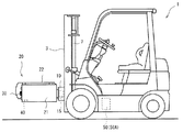
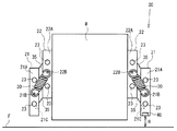
図1に示すようにクランプリフト1には、車両の前方にマスト3が設けられている。マスト3には、マスト3を昇降させるための油圧シリンダ7が備えられている。マスト3の前面には、ブラケット10を介してアーム21を有した把持装置20が前方に延出して設けられている。なお、マスト3および油圧シリンダ7はブラケット10および把持装置20を上下に昇降させるためのアーム昇降手段である。
(First embodiment)
Hereinafter, the gripping device according to the first embodiment will be described with reference to the drawings.
As shown in FIG. 1, the clamp lift 1 is provided with a
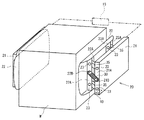
把持装置20は図2に示すように、一対のアーム21と一対の把持プレート22を有する。一対の把持プレート22は、対向する左右一対のアーム21の間に設けられている。アーム21は矩形の板状であり、アーム21の長手方向は、クランプリフト1の車両前後方向に一致する。アーム21の後端部は、ブラケット10に設けられたアクチュエータ15に接続されている。アクチュエータ15を駆動すると、一対のアーム21は左右方向にアーム21の間隔を変更する。なお、アクチュエータ15は、例えばシリンダ式またはボールネジ式を用いることができる。
As shown in FIG. 2, the
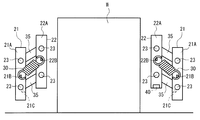
アーム21の前端部および後端部付近には、対向するアーム21の内側へ向かって起立したフランジ部21Aが設けられている。各フランジ部21Aには、2つの貫通孔がそれぞれ設けられている。各貫通孔にはピン23が挿通されている。4本のピン23には、4つのリンクバー35の一端がそれぞれ回転可能に支持されている。また、フランジ部21Aの上下中央のやや下よりの位置には、突起部21Bが設けられている。突起部21Bにはコイルばね30がその一端を支持されている。なお、リンクバー35、ピン23によりリンク機構が構成されている。また、本実施形態のコイルバネ30は引張りばねである。
Near the front end portion and the rear end portion of the
リンクバー35の他端は把持プレート22に設けられたフランジ部22Aにピン23を介して回動可能に接続されている。また、コイルばね30の他端は、フランジ部22Aの上下中央のやや上よりの位置に設けられた突起部22Bに支持されている。把持プレート22はフランジ部22Aのピン23およびリンクバー35を介してアーム21に対し上下に揺動可能に支持されている。アーム21には、図3に示すようにフランジ部21Aにストッパ21Cが設けられている。ストッパ21Cは、リンクバー35を所定の角度より下側に回転しないよう規制している。本実施形態のストッパ21Cは、リンクバー35を水平面から上方に約30度傾いた位置より下側への回転を規制する。
The other end of the
把持プレート22は、アーム21の内側に隙間を有している。把持プレート22は、リンクバー35、ピン23、ストッパ21Cによりアーム21に接続され支持されている。把持プレート22は、ワークなどに当接してアーム21側へ押されたときに、リンクバー35、ピン23によりアーム21に近接する。さらにリンクバー35が上方へ傾動すると把持プレート22がアーム21に対し上方へ揺動する。把持プレート22がアーム21側へ押される力が取り除かれると、把持プレート22はアーム21に対し下方に揺動するとともにアーム21から離隔する。
The
片方のアーム21には、前方の下端部に測距センサ40が設けられている。ここでは光学式の測距センサを使用する。測距センサ40は、アーム21の下端からアーム下方の面までの距離、つまりワークが載置される面に対するアームの相対高さを測定することができるアーム高さ検出手段である。なお、測距センサ40は、図1に示すクランプリフト1の車体に設けられた制御装置50に接続されている。制御装置50は、測距センサ40で検出されたアーム21の下端から床面までの距離、つまりアーム21の高さを一時的に記憶するメモリ50Aを有する。メモリ50Aは把持高さ記憶手段である。また、制御装置50は、クランプリフト1のアクチュエータ15を含む各部の駆動を制御するものである。本実施形態の制御装置50は、メモリ50Aに記憶されたアーム21の高さと、測距センサ40により検出されるアーム高さを比較する比較手段でもある。
One
次に本実施形態の把持装置20による荷役作業について説明する。なお、ここでは、搬送元の載置面である床面Fに載置されたワークWを搬送先の載置面fに搬送する場合を説明する。
図2に示すワークWを把持装置20にて把持して所定の搬送先へ搬送する場合、まずクランプリフト1を搬送元のワークWの正面に揺動する。次に、アクチュエータ15を駆動して一対のアーム21の間隔をワークWの幅より大きく広げる。そして、クランプリフト1を前進させて、アーム21の把持プレート22をワークWの側面に対向して位置させる。次にアクチュエータ15を駆動し一対のアーム21の間隔を狭めていく。
Next, cargo handling work by the gripping
When the workpiece W shown in FIG. 2 is gripped by the gripping
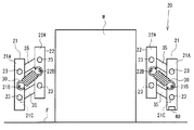
一対のアーム21の間隔を狭めていくと、図4に示すように左右の把持プレート22がワークWの側面に当接する。そして更にアーム21の間隔を狭めていくと、図5に示すように把持プレート22がリンクバー35によりアーム21に対し上方へ揺動してワークWを把持しつつ持上げる。コイルばね30は把持プレート22を下方へ戻すよう付勢する。そのため把持プレート22にはワークWを側面から把持する力が発生する。ワークWを把持しリンクバー35にて持上げるとき、ワークWは床面Fから5ミリ程度上昇する。ワークWの上昇高さはリンクバー35の長さおよびリンクバー35の傾動可能な角度によって決定されるものである。
As the distance between the pair of
図5に示すように、リンクバー35によりワークWを持上げて把持装置20がワークWの把持を完了したとき、制御装置50は、測距センサ40で検出している距離(把持高さH)をメモリ50Aに記録する。このときの把持高さHは、床面F(載置面)とアーム21との相対距離(相対高さ)である。その後、油圧シリンダ7を伸長してマスト3を上昇させて、アーム21(把持装置20)を床面Fから所定高さまで上昇させる。このときの所定高さは、例えば1メートル程度で良い。
As shown in FIG. 5, when the workpiece W is lifted by the
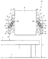
次に、ワークWを把持した状態で搬送先へクランプリフト1を走行させる。搬送先に到着したら、図6に示すように床や棚などのワークWの載置する載置面fの高さより高い位置に把持装置20を昇降させる。そしてクランプリフト1を前進させてワークWを載置面fの上方に位置させる。次に、油圧シリンダ7を駆動し把持装置20を下降させると、アーム21およびワークWが載置面fへと接近する。ここで、測距センサ40にてアーム21の下端と載置面fとの距離(アーム高さh)を検出する。なお、本実施形態では、アーム21の下降開始とともに測距センサ40でアーム高さhを測定し始める。そして、制御装置50は、メモリ50Aに記録されたワークWを把持したときのアーム21の把持高さHと、下降中のアーム21のアーム高さhを比較する。
Next, the clamp lift 1 is caused to travel to the conveyance destination while holding the workpiece W. When arriving at the transport destination, as shown in FIG. 6, the gripping
測距センサ40は、アーム21の下降中にアーム高さhの検出を続ける。制御装置50は、把持高さHと下降中のアーム高さhが同じになるまで比較を継続する。制御装置50は、把持高さHとアーム高さhが同じ値となると、油圧シリンダ7の駆動を停止し、把持装置20の下降を止める。すると、ワークWは、載置面fに対し把持したときにリンクバー35により持上がり、5ミリ程度の高さとなる。そしてアクチュエータ15を駆動してアーム21の左右の間隔を緩やかに広げる。一対のアーム21の間隔が広がると、ワークWの荷重によりリンクバー35が徐々に水平方向に傾動する。リンクバー35の傾動に伴い把持プレート22はアーム21に対し下降する。把持プレート22が下降するとワークWは載置面fへと緩やかに接近する。
The
さらにアーム21間の距離を広げリンクバー35がストッパ21Cに当接するまで傾動させる。するとワークWは載置面fに着地した状態となる。そして、アクチュエータ15によりアーム21の間隔をさらに広げる。すると、搬送先の載置面fにワークWを載置でき、搬送が完了する。
Further, the distance between the
本実施形態によれば、以下の効果を得ることができる。
(1)ワークWを把持するときの把持高さHをメモリ50Aに記憶し、ワークWを搬送先の載置面fに載置する際に測距センサ40で検出したアーム高さhと比較することで、ワークWが載置面fに着地するアーム21の高さ位置を把握することができる。
(2)制御装置50は、把持高さHとアーム高さhを比較して同じ値になったときにアーム21の下降を止めるため、ワークWに載置面fとの衝突によるダメージを与えることなく載置面fに円滑に着地させることができる。
According to the present embodiment, the following effects can be obtained.
(1) The grip height H when gripping the workpiece W is stored in the
(2) The
(3)測距センサ40はアーム21と載置面fとの距離(アーム高さh)を検出するため、ワークWを把持した床面FとワークWを載置する載置面fの高さが異なっていても、載置面fの高さに合わせてワークWを円滑に着地させることができる。そして、制御装置50に床面Fや載置面fの高さなどを予め設定しておく必要が無い。また、載置面fの高さ変更に伴う設定変更も不要である。
(4)測距センサ40は把持装置20に1つ設ければ良く、把持装置20の部品点数およびコストの増加を最小限に抑えることができる。
(3) Since the
(4) One
(5)測距センサ40でアーム高さhを検出してワークWが載置面fに当接する位置でアーム21の下降を停止するので、作業に不慣れな初心者でもワークWにダメージを与えることなく搬送作業が行える。
(6)測距センサ40によりアーム高さhを検出するので、作業者が載置面fおよびワークWの下降状況を目視で確認できない状況でもワークWにダメージを与えず載置できる。また目視で確認する必要がないので作業者の負担を軽減できる。
(5) Since the arm height h is detected by the
(6) Since the arm height h is detected by the
(7)把持装置20は、把持プレート22およびリンクバー35を用いたので、ワークWを把持すると同時に持上げることができる。また、ワークWを載置するときは、ワークWを緩やかに降ろすことができ、より一層円滑な載置が可能である。
(7) Since the
(第2の実施形態)
以下、第2の実施形態に係る把持装置60について説明する。
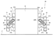
把持装置60は、第1の実施形態の把持装置20に測距センサ40を追加している。図7に示すように、測距センサ40は一対のアーム21の両方にそれぞれ設けている。測距センサ40は、左右で同じ物を用いており、アーム21への取付け位置も同じである。2つの測距センサ40はともに制御装置50に接続されている。
(Second Embodiment)
Hereinafter, the gripping
The
次に本実施形態の把持装置60による荷役作業について説明する。なお、ここでは、図7に示す床面F(載置面)に載置されたワークWを図8に示す棚Tの載置面fにおける端部付近に載置する場合について説明する。
Next, cargo handling work by the gripping
まず、作業者はクランプリフト1を操作して、図7に示すように把持装置60でワークWを把持して持上げる。把持する手順については第1の実施形態と同様である。ワークWを一対の把持プレート22で把持するとともに床面Fからわずかに上昇させる。そして、このときの測距センサ40で一対のアーム21から床面Fまでの距離(把持高さHR、HL)をメモリ50Aに記憶する。
First, the operator operates the clamp lift 1 to grip and lift the workpiece W with the
そして、図8に示すように搬送先の棚TへとワークWを搬送する。作業者はクランプリフト1を操作して把持装置60を棚Tの載置面fより高く昇降させ、棚Tの指定の載置場所の上方へワークWを位置させる。本実施形態では、把持装置60は棚Tの端部にワークWを載置する。棚Tの端部に載置する場合、図8に示すように一方(右側)のアーム21は載置面fの上方に位置する。しかし、他方(左側)のアーム21は、棚Tの端部より側方に位置する。そのため、他方(左側)のアーム21に設けられた測距センサ40は、棚Tの載置面fを検出できず、床面Fまでの距離(アーム高さhL)を検出する。
Then, as shown in FIG. 8, the work W is transported to the shelf T as the transport destination. The operator operates the clamp lift 1 to raise and lower the
制御装置50は、左右一対の測距センサ40が検出するアーム高さhR、hLが異なるとき、作業者に通知する。すると作業者は、載置面fおよびその他の異常かどうかを目視にて確認する。異常ではない場合に載置を続行するときは、作業者は左右一対の測距センサ40のどちらかの検出値を使用するか選択する。本実施形態では、一方(右側)の測距センサ40により検出した値を用いるよう決定する。
The
制御装置50は、作業者が選択した測距センサ40の検出値(アーム高さhR)を用いてアーム21の下降を開始する。そして、制御装置50は、メモリ50Aに記憶された把持高さHR、HLとアーム高さhRを比較して、アーム高さhRが把持高さHR、HLと同じになったとき、アーム21の下降を停止する。そして、第1の実施形態と同様に、アクチュエータ15によりアーム21を広げてリンクバー35を下方へ傾動させる。リンクバー35の傾動とともに把持プレート22が下降して、ワークWが棚Tの載置面fに緩やかに着地する。さらにアーム21を広げワークWの搬送を完了する。
The
本実施形態では、第1の実施形態の効果(1)から(7)に加え、以下の効果を得る。
(8)一対のアーム21に測距センサ40をそれぞれ設けたため、両側でアーム21の高さを検出することができる。
(9)制御装置50は、左右それぞれの測距センサ40による検出値が大きくことなる場合は、作業者に通知するので、載置面fに異常がある場合に誤って載置作業を続けることなくワークWにダメージを与える虞がない。
In this embodiment, in addition to the effects (1) to (7) of the first embodiment, the following effects are obtained.
(8) Since the
(9) Since the
(10)左右の測距センサ40で検出値が大きく異なる場合でも、作業者はどちらかの検出値を選択して載置作業を続行することができるので、棚Tの載置面fの端部やパレットの端部など載置する場所を有効に活用することができる。
(10) Even when the detection values of the left and right
本発明は上記実施形態に限定されるものではなく、以下に本発明の変更例について説明する。
○上記実施形態では、把持高さHとアーム高さhとを比較し、同じ値となったときにアーム21の下降を止めたが、把持高さHとアーム高さhの差が所定値以下になったときにアーム21の下降を停止しても良い。また差が小さくなるにつれ下降速度を低下させても良い。
The present invention is not limited to the above embodiment, and modifications of the present invention will be described below.
In the above embodiment, the gripping height H and the arm height h are compared, and when the values are the same, the lowering of the
○測距センサ40は、アーム21の前方下端に設けたが、アーム21の側面や後方でも載置面fまでの距離を測定できる位置であれば良い。
○測距センサ40は、光学式に限らない。アーム21の下端に設ける場合には近接センサなど多種のセンサを用いることができる。
The
The
○測距センサ40は、図9に示すように把持プレート22に設けても良い。把持プレート22に設けることで、ワークWを把持するときにリンクバー35でワークWが上昇する高さも把握することができる。
○把持装置20、60は把持プレート22を備えなくても良い。アーム21で直接ワークWを把持しても良い。
The
The
○制御装置50に床面や棚の高さを予め登録しておき、測距センサ40での検出値が登録データと大きく異なる場合などに載置面に障害物が有りなどの異常と判断しても良い。
○リンクバー35によりワークWが上方へ揺動した垂直方向の垂直移動量だけ更にアーム21を下降させても良い。この場合、把持高さHからさらにリンクバー35による持上げ分を下降させることで、ワークWを載置面fに着地させてから把持を解除することができる。
○ The height of the floor or shelf is registered in advance in the
The
○第2の実施形態において、2つの測距センサ40を設けたが、3つ以上設けても良い。また、複数の測距センサ40で載置面の傾斜を把握しても良い。
○第2の実施形態において、ワークWを把持する際に把持高さHR、HLが異なる場合にも作業者に通知し、異常でない場合はどちらかの値を選択しメモリ50Aに記憶しても良い。
In the second embodiment, two
In the second embodiment, when gripping the workpiece W, the operator is notified even when the grip heights HR and HL are different, and if it is not abnormal, either value can be selected and stored in the
○第1の実施形態および第2の実施形態において、測距センサ40は把持完了時におけるアーム21から床面Fまでの距離を検出して把持高さとして記憶したが、これに限らない。予め既定したアーム21の基準高さから床面Fまでの距離をメモリ50Aに記憶しておき、把持完了時のアームの相対高さを用いることができる。アーム21がアーム21の基準高さからの下降したか下降量を算出して把持高さを得ても良い。
In the first embodiment and the second embodiment, the
○把持プレート22は、リンクバー35、ピン23による支持に限らない。アーム21に傾斜した長孔を設けて把持プレート22側のピン23を挿通しても良い。長孔を用いても把持プレート22をアーム21に対し上下に揺動でき、近接離隔可能である。
○本発明の把持装置20、60はフォークリフトに限らず、ハンドリフトや自動倉庫のスタッカクレーンなどに適用しても良い。
The
The
1 クランプリフト
3 マスト
7 油圧シリンダ
10 ブラケット
15 アクチュエータ
20 把持装置
21 アーム
21A フランジ部
21B 突起部
21C ストッパ
22 把持プレート
22A フランジ部
22B 突起部
23 ピン
30 コイルばね
35 リンクバー
40 測距センサ
50 制御装置
50A メモリ
60 把持装置
F 床面
f 載置面
T 棚
W ワーク
DESCRIPTION OF SYMBOLS 1
Claims (6)
前記アームを昇降するアーム昇降手段と、
前記ワークが載置される載置面に対する前記アームの相対高さを検出するアーム高さ検出手段と、
載置面に載置された前記ワークを把持したときに前記アーム高さ検出手段により検出された前記アームの相対高さより得られる把持高さを記憶する把持高さ記憶手段と、
前記把持高さ記憶手段に記憶した把持高さと前記アーム高さ検出手段により検出されるアーム高さとを比較する比較手段とを備えたことを特徴とする把持装置。 An arm for gripping the workpiece;
Arm lifting means for lifting and lowering the arm;
Arm height detecting means for detecting a relative height of the arm with respect to a mounting surface on which the workpiece is mounted;
A grip height storage means for storing a grip height obtained from a relative height of the arm detected by the arm height detection means when gripping the work placed on the placement surface;
A gripping apparatus comprising: a comparison means for comparing a grip height stored in the grip height storage means with an arm height detected by the arm height detection means.
前記アームには、前記ワークに当接する一対の把持プレートと、
前記アームに前記把持プレートを接続して支持し、前記把持プレートが前記アームに近接するとき前記把持プレートを上方へ揺動させ、前記把持プレートが前記アームから離隔するときに前記把持プレートを下方へ揺動させるリンク機構とを備えたことを特徴とする請求項1乃至請求項3のいずれか一項に記載の把持装置。 The arms are a pair of arms,
The arm includes a pair of gripping plates that come into contact with the workpiece,
The grip plate is connected to and supported by the arm, the grip plate is swung upward when the grip plate is close to the arm, and the grip plate is moved downward when the grip plate is separated from the arm. The gripping device according to any one of claims 1 to 3, further comprising a link mechanism that swings.
前記アーム昇降手段は、前記リンク機構により前記把持プレートが前記アームに対し上方へ揺動した垂直移動量だけ更に前記アームを下降させることを特徴とする請求項4に記載の把持装置。 The arm height detection means is provided at the lower end of the arm,
5. The gripping apparatus according to claim 4, wherein the arm elevating means further lowers the arm by a vertical movement amount in which the gripping plate swings upward with respect to the arm by the link mechanism.
Priority Applications (1)
| Application Number | Priority Date | Filing Date | Title |
|---|---|---|---|
| JP2011065501A JP2012201432A (en) | 2011-03-24 | 2011-03-24 | Gripping device |
Applications Claiming Priority (1)
| Application Number | Priority Date | Filing Date | Title |
|---|---|---|---|
| JP2011065501A JP2012201432A (en) | 2011-03-24 | 2011-03-24 | Gripping device |
Publications (1)
| Publication Number | Publication Date |
|---|---|
| JP2012201432A true JP2012201432A (en) | 2012-10-22 |
Family
ID=47182818
Family Applications (1)
| Application Number | Title | Priority Date | Filing Date |
|---|---|---|---|
| JP2011065501A Withdrawn JP2012201432A (en) | 2011-03-24 | 2011-03-24 | Gripping device |
Country Status (1)
| Country | Link |
|---|---|
| JP (1) | JP2012201432A (en) |
Cited By (2)
| Publication number | Priority date | Publication date | Assignee | Title |
|---|---|---|---|---|
| WO2019235692A1 (en) * | 2018-06-07 | 2019-12-12 | Park Sang Uk | Hand lift device |
| KR20200002553A (en) * | 2018-06-29 | 2020-01-08 | 박상욱 | Cargo loading unit and hand lift apparatus including the same |
-
2011
- 2011-03-24 JP JP2011065501A patent/JP2012201432A/en not_active Withdrawn
Cited By (3)
| Publication number | Priority date | Publication date | Assignee | Title |
|---|---|---|---|---|
| WO2019235692A1 (en) * | 2018-06-07 | 2019-12-12 | Park Sang Uk | Hand lift device |
| KR20200002553A (en) * | 2018-06-29 | 2020-01-08 | 박상욱 | Cargo loading unit and hand lift apparatus including the same |
| KR102135248B1 (en) * | 2018-06-29 | 2020-07-17 | 박상욱 | Cargo loading unit and hand lift apparatus including the same |
Similar Documents
| Publication | Publication Date | Title |
|---|---|---|
| JP6256702B2 (en) | Container lifting and lowering transport device for article transport | |
| JP5831641B2 (en) | Transfer equipment | |
| JP4683666B2 (en) | Stage equipment | |
| TW200823128A (en) | Transfer system | |
| JP2007000940A (en) | Method and apparatus of loading pallet with glass plate | |
| CN112010049B (en) | Transfer device | |
| JP2008030057A (en) | Separating and loading apparatus | |
| JP7711304B2 (en) | Loading machine including automatic lifting unit | |
| JP4947359B2 (en) | Article conveying device | |
| JP2012201432A (en) | Gripping device | |
| JP2019172439A (en) | Article conveyance device | |
| JP2013136451A (en) | Stacker crane | |
| JP3402453B2 (en) | Article transfer device and article stacking device using the same | |
| JP4038807B2 (en) | Stacker crane | |
| JP2013067500A (en) | Conveying device | |
| CN120829013A (en) | Pick-up and release device, equipment, warehousing system, pick-up and release control method and equipment | |
| JP4973927B2 (en) | Article conveying device | |
| JP4427740B2 (en) | Article conveying device | |
| JPH10139164A (en) | Article treatment facility | |
| JP2008179427A (en) | Conveying device | |
| JP2010023963A (en) | Centering device | |
| KR102827253B1 (en) | Transporting apparatus of material | |
| JP2003321120A (en) | Cart stacking/unstacking device | |
| KR102910607B1 (en) | Transporting apparatus of material | |
| CN214269411U (en) | Material loading strutting arrangement of back of body formula container that opens door |
Legal Events
| Date | Code | Title | Description |
|---|---|---|---|
| A300 | Withdrawal of application because of no request for examination |
Free format text: JAPANESE INTERMEDIATE CODE: A300 Effective date: 20140603 |