JP2012201468A - Cord storage device - Google Patents
Cord storage device Download PDFInfo
- Publication number
- JP2012201468A JP2012201468A JP2011068504A JP2011068504A JP2012201468A JP 2012201468 A JP2012201468 A JP 2012201468A JP 2011068504 A JP2011068504 A JP 2011068504A JP 2011068504 A JP2011068504 A JP 2011068504A JP 2012201468 A JP2012201468 A JP 2012201468A
- Authority
- JP
- Japan
- Prior art keywords
- drum
- electric cord
- cord
- roller
- motor
- Prior art date
- Legal status (The legal status is an assumption and is not a legal conclusion. Google has not performed a legal analysis and makes no representation as to the accuracy of the status listed.)
- Pending
Links
- 230000002093 peripheral effect Effects 0.000 claims abstract description 29
- 238000004804 winding Methods 0.000 claims abstract description 25
- 230000005540 biological transmission Effects 0.000 claims description 6
- 230000004308 accommodation Effects 0.000 description 5
- 238000000034 method Methods 0.000 description 5
- 238000003780 insertion Methods 0.000 description 2
- 230000037431 insertion Effects 0.000 description 2
- 241000156302 Porcine hemagglutinating encephalomyelitis virus Species 0.000 description 1
- 238000005516 engineering process Methods 0.000 description 1
- 230000004048 modification Effects 0.000 description 1
- 238000012986 modification Methods 0.000 description 1
Images

Landscapes
- Storing, Repeated Paying-Out, And Re-Storing Of Elongated Articles (AREA)
Abstract
【課題】電気コードが引き出されない事態が発生することを防止しつつ、電気コードの引き出しを自動で行うことができるコード収容装置を提供する。
【解決手段】コード収容装置2は、第1電気コード4を巻き付けるためのドラム30と、ドラム30の外周面と対向する位置に配置される複数個のローラー70と、ドラム30を回転させるモーター50と、モーター50の回転をローラー70に伝達するギア36、74と、を備えている。ローラー70の回転軸72は、ドラム30の回転軸34と平行に備えられている。モーター50は、第1電気コード4がドラム30から引き出されるときには、ドラム30を正回転させ、第1電気コード4がドラム30に巻き取られるときには、ドラム30を逆回転させる。ローラー70には、ギア36、74を介してモーター50の回転が伝達される。ローラー70はドラム30と逆方向に回転する。
【選択図】図2An object of the present invention is to provide a cord storage device capable of automatically pulling out an electric cord while preventing a situation where the electric cord is not pulled out.
A cord storage device includes a drum for winding a first electric cord, a plurality of rollers disposed at positions facing an outer peripheral surface of the drum, and a motor for rotating the drum. And gears 36 and 74 that transmit the rotation of the motor 50 to the roller 70. A rotation shaft 72 of the roller 70 is provided in parallel with the rotation shaft 34 of the drum 30. The motor 50 rotates the drum 30 forward when the first electric cord 4 is pulled out from the drum 30, and reversely rotates the drum 30 when the first electric cord 4 is wound around the drum 30. The rotation of the motor 50 is transmitted to the roller 70 via the gears 36 and 74. The roller 70 rotates in the opposite direction to the drum 30.
[Selection] Figure 2
Description
本願は、電気コードを収容するコード収容装置に関する。 The present application relates to a cord accommodating device that accommodates an electric cord.
電動機器(二次電池で駆動される電動機器を含む)と電源とを接続するために電気コードが利用されている。電動機器と電源との距離は、電源の位置や電動機器の位置に応じて変化するため、電気コードの長さは想定される使用状況に応じた最大の長さに設定される。このため、使用状況によっては電気コードの長さが長すぎる場合が生じる。かかる場合、電源と電動機器との間で電気コードがたるみ、電気コードと他の機器との接触等の問題が生じ得る。そこで、必要な長さだけ電気コードを引き出せるようにしたコード収容装置が開発されている(例えば、特許文献1等)。特許文献1のコード収容装置は、筐体に回転可能に取付けられたドラムを有しており、ドラムの外周面に電気コードが巻き付けられる。電気コードは、使用時に必要な長さだけドラムから引き出される。このコード収容装置は、電気コードを巻き取る方向にドラムを回転させる駆動装置をさらに有している。電気コードをドラムに巻き取る際は、駆動装置を動作させてドラムを巻き取り方向に回転させ、使用後の電気コードがドラムに巻き取られる。 An electric cord is used to connect an electric device (including an electric device driven by a secondary battery) and a power source. Since the distance between the electric device and the power source changes according to the position of the power source and the position of the electric device, the length of the electric cord is set to the maximum length according to the assumed usage situation. For this reason, the length of the electric cord may be too long depending on the use situation. In such a case, the electric cord may sag between the power source and the electric device, and problems such as contact between the electric cord and other devices may occur. Therefore, a cord storage device has been developed that can draw out an electric cord by a required length (for example, Patent Document 1). The cord storage device of Patent Document 1 has a drum rotatably attached to a housing, and an electric cord is wound around the outer peripheral surface of the drum. The electrical cord is drawn from the drum as long as necessary for use. The cord storage device further includes a driving device that rotates the drum in a direction in which the electric cord is wound. When winding the electric cord around the drum, the driving device is operated to rotate the drum in the winding direction, and the used electric cord is wound around the drum.
特許文献1のコード収容装置では、電気コードをドラムに巻き取るときにのみ駆動装置によりドラムを回転駆動する。このため、ドラムから電気コードを引き出す際は、使用者が手動でドラムを回転させて、電気コードを引き出さなければならない。電気コードが長くなり、あるいは、電気コード自体が重いと、電気コードをドラムから引き出すために大きな力が必要となる。このため、駆動装置が電気コードを引き出す方向にドラムを回転駆動し、電気コードがドラムから自動的に引き出されれば便利である。しかしながら、ドラムに対する電気コードのすべり等によって、ドラムから引き出される電気コードの長さと比較して、ドラムの回転量が多くなることがある。すると、ドラムに巻き付けられている電気コードの巻き付けが緩み、電気コードがドラムの外周面から離れてしまう。その結果、ドラムが回転しても、ドラムから電気コードが送り出されない事態が生じてしまう。 In the cord storage device of Patent Document 1, the drum is rotated by the driving device only when the electric cord is wound around the drum. For this reason, when pulling out the electric cord from the drum, the user must manually rotate the drum and pull out the electric cord. If the electric cord becomes long or the electric cord itself is heavy, a large force is required to pull out the electric cord from the drum. For this reason, it is convenient if the driving device rotates the drum in the direction in which the electric cord is pulled out and the electric cord is automatically pulled out from the drum. However, the amount of rotation of the drum may increase compared to the length of the electric cord drawn from the drum due to slippage of the electric cord with respect to the drum. Then, the winding of the electric cord wound around the drum is loosened, and the electric cord is separated from the outer peripheral surface of the drum. As a result, even if the drum rotates, a situation occurs in which the electric cord is not sent out from the drum.
本願は、上記した実情に鑑みてなされたものであり、電気コードが引き出されない事態が発生することを防止しつつ、電気コードの引き出しを自動で行うことができるコード収容装置を提供する。 The present application has been made in view of the above circumstances, and provides a cord storage device that can automatically pull out an electric cord while preventing a situation in which the electric cord is not pulled out.
本願のコード収容装置は、電気コードを収容する収容装置であって、電気コードを巻き付けるためのドラムと、ドラムの外周面と対向する位置に配置される少なくとも1個のローラーと、ドラムを回転させるモーターと、モーターの回転をローラーに伝達する伝達機構と、を備えている。ローラーは、その回転軸がドラムの回転軸と平行となると共に、その外周面がドラムの外周面と対向するように備えられている。モーターは、電気コードがドラムから引き出されるときには、ドラムを第1の方向に回転させ、電気コードがドラムに巻き取られるときには、ドラムを第1の方向とは逆の第2の方向に回転させる。伝達機構は、ローラーが、ドラムの回転方向と逆方向に回転するように、モーターの回転を伝達する。 The cord storage device of the present application is a storage device that stores an electrical cord, and is configured to rotate a drum for winding the electrical cord, at least one roller disposed at a position facing the outer peripheral surface of the drum, and the drum. A motor, and a transmission mechanism that transmits the rotation of the motor to the roller. The roller is provided such that its rotating shaft is parallel to the rotating shaft of the drum and its outer peripheral surface faces the outer peripheral surface of the drum. The motor rotates the drum in a first direction when the electric cord is pulled out of the drum, and rotates the drum in a second direction opposite to the first direction when the electric cord is wound around the drum. The transmission mechanism transmits the rotation of the motor so that the roller rotates in the direction opposite to the rotation direction of the drum.
このコード収容装置では、ドラムがモーターによって回転される。モーターは、電気コードがドラムから引き出されるときにはドラムを第1の方向に回転させ、電気コードがドラムに巻き取られるときにはドラムを第2の方向に回転させる。即ち、このコード収容装置では、電気コードの巻き取りがモーターの回転によって自動的に行われるとともに、電気コードの引き出しもモーターの回転によって自動的に行われる。電気コードをドラムから引き出す際に、電気コードの巻き付けが緩んで、電気コードがドラムの外周面から離れた場合は、その電気コードはローラーと接触する。ローラーには、モーターの回転が伝達機構を介して伝達され、ローラーは、ドラムの回転方向とは逆方向に回転している。このため、ローラーに接触した電気コードは、ローラーによってコード引き出し方向に送られることとなる。その結果、ドラムを第1の方向に回転させても、電気コードがドラムから引き出されないという事態が発生することを防止することができる。 In this cord storage device, the drum is rotated by a motor. The motor rotates the drum in the first direction when the electric cord is pulled out of the drum, and rotates the drum in the second direction when the electric cord is wound around the drum. That is, in this cord storage device, the winding of the electric cord is automatically performed by the rotation of the motor, and the drawing of the electric cord is also automatically performed by the rotation of the motor. When the electric cord is pulled out from the drum, if the winding of the electric cord is loosened and the electric cord is separated from the outer peripheral surface of the drum, the electric cord comes into contact with the roller. The rotation of the motor is transmitted to the roller via a transmission mechanism, and the roller rotates in the direction opposite to the rotation direction of the drum. For this reason, the electric cord in contact with the roller is sent in the cord drawing direction by the roller. As a result, even if the drum is rotated in the first direction, it is possible to prevent a situation in which the electric cord is not pulled out from the drum.
ドラムの外周面に電気コードが密に巻き付けられた場合に、ドラムに巻き付けられた電気コードとローラーとの間にクリアランスができるように、ドラムに対するローラーの位置が調整されていることが好ましい。この構成によると、ドラムに巻き付けられた電気コードの巻き付けが緩み、電気コードがドラムの外周面から離れた場合にのみ、ローラーが電気コードと接触する。ローラーがドラムに巻き付けられた電気コードと常時接触する構成と比べて、電気コードの外周被覆材が傷つき難い。 When the electric cord is tightly wound around the outer peripheral surface of the drum, the position of the roller with respect to the drum is preferably adjusted so that a clearance is formed between the electric cord wound around the drum and the roller. According to this configuration, the roller comes into contact with the electric cord only when the winding of the electric cord wound around the drum is loosened and the electric cord is separated from the outer peripheral surface of the drum. Compared to the configuration in which the roller is always in contact with the electric cord wound around the drum, the outer periphery covering material of the electric cord is less likely to be damaged.
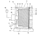
本実施例のコード収容装置2は、電気自動車(EV)又はプラグ・イン・ハイブリッド自動車(PHEV)に搭載される。コード収容装置2は、電気自動車等に搭載されるバッテリを充電するための電気コードを収容する。図1に示すように、本実施例のコード収容装置2は、ハウジング10と、ドラム30と、モーター50と、複数個(本実施例では16個)のローラー70と、一対のガイドローラー80を備える。
The
本実施例のコード収容装置2に収容される電気コードは、外部電源(図示省略)と自動車(図示省略)とを接続し、自動車に搭載されたバッテリを充電するためのコードである。電気コードは、外部電源と接続するための第1電気コード4と、車載バッテリに接続するための第2電気コード6とを備える。なお、本実施例では、第1電気コード4がハウジング10内に収容される。
The electric cord housed in the
第1電気コード4の一端には、外部電源と接続するためのプラグ5が備えられている。プラグ5には、引き出しスイッチ5a、巻き取りスイッチ5b、停止スイッチ5cが形成されている。各スイッチ5a〜5cについては後で説明する。本実施例では、第1電気コード4は、第2電気コード6より長く形成されている。第1電気コード4の他端は、ハウジング10内のドラム30に固定されているとともに、ハウジング10内のコネクタ20(図2参照)と電気的に接続されている。図2に示すように、第1電気コード4の中間部はドラム30に巻き付けられる。本実施例では、ドラム30に巻き付けられている第1電気コード4が、必要に応じてハウジング10外に引き出され、又は、ドラム30に巻き取られてハウジング10内に収容される。
One end of the first
一方、第2電気コード6の一端には、車載バッテリと接続するための接続コネクタ7が備えられている。第2電気コード6の他端は、図2に示されているように、ハウジング10内に導入されるとともに、ハウジング10内に設けられたコネクタ20と電気的に接続されている。これにより、第1電気コード4と第2電気コード6とはコネクタ20を介して電気的に接続される。本実施例では、第2電気コード6の長さは第1電気コード4の長さより短く形成されている。また、本実施例では、第2電気コード6は、ドラム30に巻き付けられていない。そのため、第2電気コード6がハウジング10外に引き出されたり、ハウジング10内に収容されたりすることはない。第2電気コード6は、常に所定の長さ分だけハウジング10の外に引き出されている。
On the other hand, one end of the second
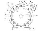
図2に示すように、ハウジング10は、第1側板12と、第2側板14と、基部16とを備える。第1側板12と第2側板14との間には収容空間11が形成されている。収容空間11内には、図3に示すように、ドラム30と、ドラム30に巻き付けられた第1電気コード4と、複数個のローラー70と、一対のガイドローラー80とが収容されている。また、図2に示すように、第1側板12の外側面には、モーター50が備えられている。なお、第1側板12には、第2電気コード6を挿通させるための挿通孔18が開口されている。また、第1側板12の内側面には、コネクタ20が備えられている。
As shown in FIG. 2, the
ドラム30は、第1電気コード4を巻き付けるための部材である。ドラム30は、断面が円形の円筒状に形成されている。ドラム30の外周面には、第1電気コード4を案内するための案内溝32が形成されている。ドラム30の軸方向一端は、円板部33によって閉塞されている。また、ドラム30の軸方向他端は、外周縁に歯が形成された円板状のギア36によって閉塞されている。本実施例では、ギア36の径は、ドラム30の外径より大きく形成されている。ドラム30の軸線に沿って回転軸34が備えられている。回転軸34は、円板部33及びギア36を貫通するとともに、円板部33及びギア36に固定されている。そのため、回転軸34が回転すると、ドラム30とギア36が回転軸34の回転方向と同じ方向に回転する。回転軸34の両端部は、それぞれ、側板12、14を貫通するとともに、側板12、14に対して回転自在に取り付けられている。また、回転軸34の一端には、ドラム30を回転させるためのモーター50が備えられている。そのため、モーター50が回転することで、回転軸34が回転し、ドラム30及びギア36が回転する。
The
モーター50には、制御装置60が電気的に接続されている。制御装置60は、モーター50の回転と停止を制御するとともに、モーター50の回転方向(正方向又は逆方向)を制御する。さらに、制御装置60は、第1電気コード4のプラグ5に設けられているスイッチ5a〜5c(図1参照)と電気的に接続されている。本実施例では、引き出しスイッチ5aが押されると、制御装置60は、モーター50を一方向に回転(以下では「正回転」と呼ぶ)させる。モーター50が正回転すると、それに伴ってドラム30が正回転し、第1電気コード4がハウジング10の外側に引き出される。一方、巻き取りスイッチ5bが押されると、制御装置60は、モーター50を上記と逆の方向に回転(以下では「逆回転」と呼ぶ)し、それに伴ってドラム30が逆回転し、引き出された第1電気コード4がドラム30に巻き取られる。また、停止スイッチ5cが押されると、制御装置60は、モーター50の駆動を停止させる。
A
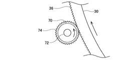
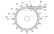
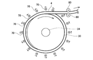
図3に示すように、複数個(16個)のローラー70は、ドラム30の外周面と対向する位置に配置されている。各ローラー70は、周方向に略等間隔に配置されている。各ローラー70の配置位置は、ドラム30の外周面に第1電気コード4が密に巻き付けられた場合に、ドラム30に巻き付けられた第1電気コード4と各ローラー70との間にクリアランスができるように調整されている。すなわち、ドラム30の外周面からローラー70の軸線までの距離が、ローラー70の半径よりも大きくなるように調整されている。ローラー70は、断面が円形の円柱状に形成されている。図2に示すように、ローラー70の一端には、外周縁に歯が形成された円板状のギア74が備えられている。ギア74の径は、ローラー70の外径より大きく形成されている。さらに、ローラー70の軸線に沿って回転軸72が備えられている。回転軸72は、ローラー70及びギア74を貫通するとともに、ローラー70及びギア74に固定されている。回転軸72の両端は、それぞれ、側板12、14に回転自在に取り付けられている。また、回転軸72は、ドラム30の回転軸34と平行となっている。また、図4に示すように、ローラー70とドラム30とは、ギア74の歯とギア36の歯とが噛み合うように配置されている。そのため、図4に示すように、ドラム30の回転方向とローラー70の回転方向とは逆方向となる。例えば、ドラム30が正回転すると、ギア36とギア74によってモーター50の回転がローラー70に伝達され、ローラー70はドラム30の回転方向と逆方向に回転(逆回転)する。
As shown in FIG. 3, a plurality (16) of
図3に示すように、一対のガイドローラー80は、ハウジング10の外周縁部分に備えられている。ガイドローラー80は、回転軸82に対して回転自在に備えられている。図3に示すように、一対のガイドローラー80は、対向する外周面の間に第1電気コード4を挟んでいる。一対のガイドローラー80は、ドラム30から引き出される第1電気コード4、又は、ドラム30に巻き取られる第1電気コード4を案内する。
As shown in FIG. 3, the pair of
(引き出し動作)
続いて、図5、図6を参照して、ドラム30に巻き付けられている第1電気コード4を引き出す場合のコード収容装置2の動作を説明する。ドラム30に巻き付けられている第1電気コード4を引き出す場合、まず、ユーザは、プラグ5の引き出しスイッチ5a(図1参照)を押す。ユーザが引き出しスイッチ5aを押すと、制御装置60は、モーター50を正回転させる。モーター50の正回転に伴い、図5に示すように、ドラム30が正回転する。ドラム30が正回転すると、ドラム30に巻き付けられている第1電気コード4は、ガイドローラー80に案内されて、ハウジング10外に引き出される方向に送られる。その結果、ドラム30内に巻き付けられている第1電気コード4は、ハウジング10外に引き出される。なお、このとき、各ローラー70は、ドラム30の回転方向と逆方向に回転(逆回転)している。図5に示す例では、第1電気コード4はドラム30の外周面に接触しており、第1電気コード4と各ローラー70とは接触しない。
(Drawer operation)
Next, with reference to FIGS. 5 and 6, the operation of the
上記の第1電気コード4の引き出し工程において、図6に示すように、ドラム30に巻き付けられた第1電気コード4の巻き付けが緩み、第1電気コード4がドラム30の外周面から離れる場合がある。その場合、巻き付けが緩んでドラム30から離れた第1電気コード4が、逆回転するローラー70に接触する。ローラー70に接触した第1電気コード4は、逆回転するローラー70によって、ハウジング10外に引き出される方向に送られる。その結果、第1電気コード4がドラム30の外周面から離れても、第1電気コード4はドラム30からハウジング10外へと引き出される。
In the step of drawing out the first
上記の第1電気コード4の引き出し工程の途中で、ユーザが停止スイッチ5cを押すと、制御装置60は、モーター50の駆動を停止させる。その後、ユーザが引き出しスイッチ5aを再度押すと、制御装置60はモーター50を再度正回転させ、第1電気コード4の引き出しが再開される。引き出し工程の結果、第1電気コード4が最大長まで引き出されると、制御装置60はモーター50の駆動を自動的に停止させる。
When the user presses the
(巻き取り動作)
ハウジング10外に引き出されている第1電気コード4をドラム30に巻き取らせてハウジング10内に収容する場合、まず、ユーザは、プラグ5の巻き取りスイッチ5b(図1参照)を押す。ユーザが巻き取りスイッチ5bを押すと、制御装置60は、モーター50を逆回転させる。モーター50の逆回転に伴い、ドラム30が逆回転する。ドラム30が逆回転すると、ハウジング10外に引き出されている第1電気コード4は、ガイドローラー80に案内されて、ドラム30に巻き取られる方向に送られる。その結果、ハウジング10外に引き出されている第1電気コード4は、ドラム30に巻き取られる。なお、このとき、各ローラー70は、ドラム30の回転方向と逆方向に回転(正回転)している。第1電気コード4がドラム30に巻き取られる工程では、第1電気コード4が一対のガイドローラー80の間を通ってドラム30に巻き取られるため、第1電気コード4には適切なテンションが作用する。このため、第1電気コード40は、ドラム30に密に巻き付けられながら巻き取られ、第1電気コード4がローラー70に接触することはない。
(Winding operation)
When the first
上記の第1電気コード4の巻き取り工程の途中で、ユーザが停止スイッチ5cを押すと、制御装置60は、モーター50の駆動を停止させる。その後、ユーザが巻き取りスイッチ5bを再度押すと、制御装置60はモーター50を再度逆回転させ、第1電気コード4の巻き取りが再開される。巻き取り工程の結果、プラグ5がガイドローラー80と接触する位置まで第1電気コード4が巻き取られると、制御装置60はモーター50の駆動を自動的に停止させる。
When the user presses the
以上、本実施例のコード収容装置2について説明した。本実施例と請求項の記載の対応関係を説明しておく。ドラム30の正回転、逆回転が、それぞれ、「第1の方向に回転」、「第2の方向に回転」の一例である。また、ギア36及びギア74が、「伝達機構」の一例である。
Heretofore, the
上述の通り、本実施例のコード収容装置2では、ドラム30は、モーター50によって回転される。モーター50は、第1電気コード4が引き出されるときには、ドラム30を正回転させ、第1電気コード4が巻き取られるときには、ドラム30を逆回転させる。即ち、本実施例では、第1電気コード4の巻き取りがモーター50の回転によって自動的に行われるとともに、第1電気コード4の引き出しもモーター50の回転によって自動的に行われる。また、本実施例では、図6に示すように、第1電気コード4をドラム30から引き出す際に、第1電気コード4の巻き付けが緩んで、第1電気コード4がドラム30の外周面から離れると、その第1電気コード4はローラー70と接触する。ローラー70は、ドラム30の回転方向とは逆方向に回転しているため、ローラー70に接触した第1電気コード4は、ローラー70によって、ハウジング10外に引き出される方向に送られる。その結果、第1電気コード4がドラム30の外周面から離れても、第1電気コード4がドラム30から引き出されないという事態の発生を防止することができる。これによって、第1電気コード4のドラム30からの引き出しとドラム30への巻き取りを自動で行うことができる。
As described above, in the
また、本実施例では、図3に示すように、ドラム30に巻き付けられた第1電気コード4とローラー70との間にクリアランスが形成されている。このため、ドラム30に巻き付けられる第1電気コード4の巻き付けが緩み、第1電気コード4がドラム30の外周面から離れた場合にのみ、ローラー70は第1電気コード4と接触する。ローラー70が、ドラム30に巻き付けられる第1電気コード4と常時接触する構成と比べて、第1電気コード4の外周被覆材が傷つき難い。
In this embodiment, as shown in FIG. 3, a clearance is formed between the first
上記の実施例の変形例を説明する。
(1)上記の実施例では、ドラム30に巻き付けられた第1電気コード4とローラー70との間にクリアランスが形成されていたが、これに代えて、ローラー70が、ドラム30に巻き付けられる第1電気コード4と常時接触するようにしてもよい。その場合、ローラー70が、ドラム30の外周面方向に向かってばね等によって付勢されていてもよい。
(2)上記の実施例では、ローラー70は複数個(16個)備えられている。ローラー70の配置数は、これには限られず、1個以上であれば任意の数とすることができる。
(3)上記の実施例では、第1電気コード4側に外部電源と接続するためのプラグ5を備え、第2電気コード6側に車載バッテリと接続するための接続コネクタ7が備えられている。これに代えて、第1電気コード4側に接続コネクタを備え、第2電気コード6側にプラグを備えてもよい。なお、この場合、引き出しスイッチ、巻き取りスイッチ、停止スイッチの各スイッチは、接続コネクタに形成されてもよい。
(4)なお、引き出しスイッチ、巻き取りスイッチ、停止スイッチの各スイッチは、プラグや接続コネクタに限らず、任意の場所に形成されてもよい。
A modification of the above embodiment will be described.
(1) In the above embodiment, the clearance is formed between the first
(2) In the above embodiment, a plurality (16) of
(3) In the above-described embodiment, the first
(4) Note that each of the drawer switch, the take-up switch, and the stop switch is not limited to the plug and the connection connector, and may be formed at any place.
本明細書または図面に説明した技術要素は、単独であるいは各種の組み合わせによって技術的有用性を発揮するものであり、出願時請求項記載の組み合わせに限定されるものではない。また、本明細書または図面に例示した技術は複数目的を同時に達成するものであり、そのうちの一つの目的を達成すること自体で技術的有用性を持つものである。 The technical elements described in this specification or the drawings exhibit technical usefulness alone or in various combinations, and are not limited to the combinations described in the claims at the time of filing. In addition, the technology illustrated in the present specification or the drawings achieves a plurality of objects at the same time, and has technical utility by achieving one of the objects.
2:コード収容装置
4:第1電気コード
5:プラグ
5a:引き出しスイッチ
5b:巻き取りスイッチ
5c:停止スイッチ
6:第2電気コード
7:接続コネクタ
10:ハウジング
11:収容空間
12:側板
14:側板
16:基部
18:挿通孔
20:コネクタ
30:ドラム
32:案内溝
33:円板部
34:回転軸
36:ギア
50:モーター
60:制御装置
70:ローラー
72:回転軸
74:ギア
80:ガイドローラー
82:回転軸
2: Cord storage device 4: First electrical cord 5:
Claims (2)
電気コードを巻き付けるためのドラムと、
ドラムの外周面と対向する位置に配置される少なくとも1個のローラーと、
ドラムを回転させるためのモーターと、
モーターの回転をローラーに伝達する伝達機構と、を備えており、
ローラーは、その回転軸がドラムの回転軸と平行となると共に、その外周面がドラムの外周面と対向するように備えられており、
モーターは、電気コードがドラムから引き出されるときには、ドラムを第1の方向に回転させ、電気コードがドラムに巻き取られるときには、ドラムを第1の方向とは逆の第2の方向に回転させ、
伝達機構は、ローラーが、ドラムの回転方向と逆方向に回転するように、モーターの回転を伝達する、コード収容装置。 A storage device for storing an electrical cord,
A drum for winding an electric cord;
At least one roller disposed at a position facing the outer peripheral surface of the drum;
A motor for rotating the drum,
A transmission mechanism for transmitting the rotation of the motor to the roller,
The roller is provided such that its rotation axis is parallel to the rotation axis of the drum and its outer peripheral surface faces the outer peripheral surface of the drum.
The motor rotates the drum in a first direction when the electric cord is pulled out of the drum, and rotates the drum in a second direction opposite to the first direction when the electric cord is wound around the drum,
The transmission mechanism is a cord storage device that transmits the rotation of the motor so that the roller rotates in the direction opposite to the rotation direction of the drum.
Priority Applications (1)
| Application Number | Priority Date | Filing Date | Title |
|---|---|---|---|
| JP2011068504A JP2012201468A (en) | 2011-03-25 | 2011-03-25 | Cord storage device |
Applications Claiming Priority (1)
| Application Number | Priority Date | Filing Date | Title |
|---|---|---|---|
| JP2011068504A JP2012201468A (en) | 2011-03-25 | 2011-03-25 | Cord storage device |
Publications (1)
| Publication Number | Publication Date |
|---|---|
| JP2012201468A true JP2012201468A (en) | 2012-10-22 |
Family
ID=47182844
Family Applications (1)
| Application Number | Title | Priority Date | Filing Date |
|---|---|---|---|
| JP2011068504A Pending JP2012201468A (en) | 2011-03-25 | 2011-03-25 | Cord storage device |
Country Status (1)
| Country | Link |
|---|---|
| JP (1) | JP2012201468A (en) |
Cited By (4)
| Publication number | Priority date | Publication date | Assignee | Title |
|---|---|---|---|---|
| WO2014201233A1 (en) * | 2013-06-12 | 2014-12-18 | Graco Minnesota Inc. | Modular direct drive system for powered hose reels |
| CN106911037A (en) * | 2017-04-20 | 2017-06-30 | 宁波市协新机电科技有限公司 | A kind of bridge equipment |
| CN107720457A (en) * | 2017-11-13 | 2018-02-23 | 山东交通学院 | A kind of practical cable for ship winch |
| WO2021029593A1 (en) * | 2019-08-09 | 2021-02-18 | 제일정보기술 주식회사 | Apparatus for lifting electric vehicle charging cable |
Citations (2)
| Publication number | Priority date | Publication date | Assignee | Title |
|---|---|---|---|---|
| JPH01121062U (en) * | 1988-02-12 | 1989-08-16 | ||
| JPH0578044A (en) * | 1991-09-18 | 1993-03-30 | Auto Service Marushin:Kk | Hose winding device |
-
2011
- 2011-03-25 JP JP2011068504A patent/JP2012201468A/en active Pending
Patent Citations (2)
| Publication number | Priority date | Publication date | Assignee | Title |
|---|---|---|---|---|
| JPH01121062U (en) * | 1988-02-12 | 1989-08-16 | ||
| JPH0578044A (en) * | 1991-09-18 | 1993-03-30 | Auto Service Marushin:Kk | Hose winding device |
Cited By (5)
| Publication number | Priority date | Publication date | Assignee | Title |
|---|---|---|---|---|
| WO2014201233A1 (en) * | 2013-06-12 | 2014-12-18 | Graco Minnesota Inc. | Modular direct drive system for powered hose reels |
| US9656833B2 (en) | 2013-06-12 | 2017-05-23 | Graco Minnesota Inc. | Modular direct drive system for powered hose reels |
| CN106911037A (en) * | 2017-04-20 | 2017-06-30 | 宁波市协新机电科技有限公司 | A kind of bridge equipment |
| CN107720457A (en) * | 2017-11-13 | 2018-02-23 | 山东交通学院 | A kind of practical cable for ship winch |
| WO2021029593A1 (en) * | 2019-08-09 | 2021-02-18 | 제일정보기술 주식회사 | Apparatus for lifting electric vehicle charging cable |
Similar Documents
| Publication | Publication Date | Title |
|---|---|---|
| CN104112958B (en) | Cable storage device and electric vehicle with same | |
| EP2733804B1 (en) | Charging cable storage device | |
| EP2687470A1 (en) | Cord accommodation apparatus | |
| US20140246534A1 (en) | Housing device | |
| JP5266237B2 (en) | Drive unit for movable furniture | |
| US9960546B2 (en) | Coiling device and household appliance having the same | |
| JPS63288874A (en) | Motor drive type cable reel device | |
| KR101830134B1 (en) | Charging cable winding apparatus | |
| JP2012201468A (en) | Cord storage device | |
| CN104953639B (en) | Automatic charging pile | |
| JP2013172618A (en) | Housing device for cable | |
| CN104577565B (en) | Automatic winder and electrical equipment | |
| JP6720011B2 (en) | Charger | |
| JP5877108B2 (en) | Cable housing device | |
| CN110775849A (en) | Winch | |
| WO2013115376A1 (en) | Cable housing device | |
| US20180202220A1 (en) | Cord Reel Device for a Window Blind | |
| CN112279129B (en) | An electric winch device | |
| JP2014180121A (en) | Automatic take-up device of charging cable | |
| GB2503892A (en) | Power cable apparatus | |
| CN217376878U (en) | Cable winding and unwinding devices of stage lift mechanical equipment | |
| CN210468019U (en) | Opposite-drawing-needle type battery cell winding head, winding device and button type battery cell sheet-making winding machine | |
| JP5432408B1 (en) | A transmission suitable for using a plurality of large-diameter thin rotary electric machines that rotate in reverse to each other as a drive motor for an electric vehicle. | |
| CN217650604U (en) | Wire rewinding device | |
| CN106276427B (en) | Efficient power cable winding device |
Legal Events
| Date | Code | Title | Description |
|---|---|---|---|
| A621 | Written request for application examination |
Free format text: JAPANESE INTERMEDIATE CODE: A621 Effective date: 20140108 |
|
| A977 | Report on retrieval |
Free format text: JAPANESE INTERMEDIATE CODE: A971007 Effective date: 20140922 |
|
| A131 | Notification of reasons for refusal |
Free format text: JAPANESE INTERMEDIATE CODE: A131 Effective date: 20140930 |
|
| A02 | Decision of refusal |
Free format text: JAPANESE INTERMEDIATE CODE: A02 Effective date: 20150210 |