JP2012202043A - Method for excavating slope of ground - Google Patents
Method for excavating slope of ground Download PDFInfo
- Publication number
- JP2012202043A JP2012202043A JP2011065336A JP2011065336A JP2012202043A JP 2012202043 A JP2012202043 A JP 2012202043A JP 2011065336 A JP2011065336 A JP 2011065336A JP 2011065336 A JP2011065336 A JP 2011065336A JP 2012202043 A JP2012202043 A JP 2012202043A
- Authority
- JP
- Japan
- Prior art keywords
- slope
- gantry
- excavator
- ground
- excavating
- Prior art date
- Legal status (The legal status is an assumption and is not a legal conclusion. Google has not performed a legal analysis and makes no representation as to the accuracy of the status listed.)
- Granted
Links
- 238000000034 method Methods 0.000 title claims abstract description 14
- 238000009412 basement excavation Methods 0.000 claims description 31
- 230000002093 peripheral effect Effects 0.000 claims description 21
- 239000004576 sand Substances 0.000 claims description 15
- NJPPVKZQTLUDBO-UHFFFAOYSA-N novaluron Chemical compound C1=C(Cl)C(OC(F)(F)C(OC(F)(F)F)F)=CC=C1NC(=O)NC(=O)C1=C(F)C=CC=C1F NJPPVKZQTLUDBO-UHFFFAOYSA-N 0.000 claims description 7
- XLYOFNOQVPJJNP-UHFFFAOYSA-N water Substances O XLYOFNOQVPJJNP-UHFFFAOYSA-N 0.000 claims description 3
- 239000011435 rock Substances 0.000 claims description 2
- 238000005259 measurement Methods 0.000 description 9
- 238000004891 communication Methods 0.000 description 6
- 230000008878 coupling Effects 0.000 description 6
- 238000010168 coupling process Methods 0.000 description 6
- 238000005859 coupling reaction Methods 0.000 description 6
- 238000005553 drilling Methods 0.000 description 4
- 238000006243 chemical reaction Methods 0.000 description 2
- 239000002184 metal Substances 0.000 description 2
- 238000009434 installation Methods 0.000 description 1
- 238000004080 punching Methods 0.000 description 1
- 239000011150 reinforced concrete Substances 0.000 description 1
- 239000013049 sediment Substances 0.000 description 1
- 239000002023 wood Substances 0.000 description 1
Images








Landscapes
- Engineering & Computer Science (AREA)
- Structural Engineering (AREA)
- General Engineering & Computer Science (AREA)
- Earth Drilling (AREA)
- Civil Engineering (AREA)
- Mining & Mineral Resources (AREA)
- Mechanical Engineering (AREA)
- Life Sciences & Earth Sciences (AREA)
- General Life Sciences & Earth Sciences (AREA)
- Paleontology (AREA)
Abstract
Description
本発明は、地盤の斜面を掘削する方法に関する。 The present invention relates to a method for excavating a ground slope.
従来、地盤の斜面を掘削する方法には、前記斜面の傾斜方向に伸びるレールを前記斜面に敷設し、次に、掘削機を前記斜面の下から該斜面における掘削位置へ前記レールの上で移動させ、その後、前記掘削位置で前記掘削機により前記斜面を掘削するものがある(特許文献1参照)。 Conventionally, a method of excavating the slope of the ground includes laying a rail extending in the slope direction of the slope on the slope, and then moving the excavator from below the slope to the excavation position on the slope on the rail. And then excavating the slope with the excavator at the excavation position (see Patent Document 1).
前記掘削機を前記斜面の下から前記掘削位置へ前記レールの上で移動させるため、前記掘削機を前記斜面の下から前記掘削位置へ搬入するための搬入路を前記斜面に設けることを要しない。このため、前記斜面に前記搬入路を設けるために多くの手間と時間とをかけることなく、また、前記搬入路のためのスペースの有無に拘わらず、前記斜面を掘削することができる。 In order to move the excavator from below the slope to the excavation position on the rail, it is not necessary to provide a loading path on the slope to carry the excavator from below the slope to the excavation position. . For this reason, it is possible to excavate the slope without providing much time and effort to provide the carry-in path on the slope and regardless of whether there is a space for the carry-in path.
しかし、前記斜面の下から前記掘削位置へ前記レールの上で移動させた前記掘削機により前記斜面を掘削するため、前記斜面に前記レールを敷設することを要し、前記斜面への前記レールの敷設に多くの手間と時間とがかかる。このため、前記斜面の掘削を効率的に行うことができない。 However, in order to excavate the slope by the excavator moved on the rail from below the slope to the excavation position, it is necessary to lay the rail on the slope, and the rail to the slope It takes a lot of work and time to install. For this reason, excavation of the slope cannot be performed efficiently.
本発明の目的は、地盤の斜面に掘削機のためのレールを敷設することなく前記掘削機により前記斜面を掘削できるようにすることにより、前記斜面への前記レールの敷設に多くの手間と時間とをかけることなく前記斜面を効率的に掘削できるようにすることである。 An object of the present invention is to enable the excavator to excavate the slope without laying a rail for the excavator on the ground slope, thereby laying the rail on the slope with a lot of labor and time. It is to be able to excavate the slope efficiently without applying a slack.
本発明は、掘削機が載せられた架台を吊り上げかつ地盤の斜面から隔てられた該地盤の上の位置から前記斜面へ移動させた後、前記掘削機により前記斜面を掘削する。これにより、前記斜面に前記掘削機のためのレールを敷設することなくなく前記掘削機により前記斜面を掘削できるようにし、前記斜面への前記レールの敷設に多くの手間と時間とをかけることなく前記斜面を効率的に掘削できるようにする。 In the present invention, after the platform on which the excavator is mounted is lifted and moved from the position on the ground separated from the slope of the ground to the slope, the slope is excavated by the excavator. Accordingly, the slope can be excavated by the excavator without laying rails for the excavator on the slope, and much time and effort are not required for laying the rail on the slope. To enable efficient excavation of the slope.
本発明に係る、地盤の斜面を掘削する方法は、前記斜面から隔てられた前記地盤の上の位置に架台を配置する第1ステップと、前記架台に掘削機を載せる第2ステップと、前記掘削機が載せられた前記架台を吊り上げかつ前記位置から前記斜面へ移動させる第3ステップと、前記掘削機により前記斜面を掘削する第4ステップとを含む。 According to the present invention, there is provided a method for excavating a slope of a ground, a first step of placing a pedestal at a position on the ground separated from the slope, a second step of placing an excavator on the pedestal, and the excavation A third step of lifting the platform on which the machine is mounted and moving the platform from the position to the slope, and a fourth step of excavating the slope by the excavator.
前記掘削機が載せられた前記架台を吊り上げかつ前記位置から前記斜面へ移動させた後、前記掘削機により前記斜面を掘削するため、前記掘削機を前記斜面の下から該斜面における掘削位置へレールの上で移動させた後に前記掘削位置で前記掘削機により前記斜面を掘削する従来の場合のように前記斜面に前記レールを敷設することを要しない。このため、前記斜面への前記レールの敷設に多くの手間と時間とをかけることなく前記斜面を効率的に掘削することができる。 After lifting the platform on which the excavator is mounted and moving the excavator from the position to the slope, the excavator is railed from below the slope to an excavation position on the slope to excavate the slope. It is not necessary to lay the rail on the slope as in the conventional case where the slope is excavated by the excavator at the excavation position after being moved on. For this reason, the said slope can be excavated efficiently, without spending much effort and time for the installation of the said rail to the said slope.
前記架台は、周縁部と、該周縁部に設けられた、該周縁部の外方へ開放された切欠き部又は開口部とを有する平板とすることができる。この場合、前記第3ステップにおいて前記切欠き部又は前記開口部が前記斜面に近接するように前記架台を前記斜面へ移動させ、前記第4ステップの後、前記斜面の掘削により生じた土砂を前記架台の上から前記切欠き部又は前記開口部を経て前記斜面に落とす。 The gantry may be a flat plate having a peripheral edge and a notch or an opening provided on the peripheral edge and opened outward from the peripheral edge. In this case, in the third step, the platform is moved to the slope so that the notch or the opening is close to the slope, and after the fourth step, the earth and sand generated by excavation of the slope is removed. It drops onto the slope through the notch or the opening from above the gantry.
前記切欠き部又は前記開口部が前記斜面に近接するように前記架台を前記斜面へ移動させた後、前記斜面の掘削により生じた前記土砂を前記架台の上から前記切欠き部又は前記開口部を経て前記斜面に落とすため、前記斜面を掘削した前記掘削機を旋回させることなく前記土砂を前記架台の上から前記斜面に落とすことができ、前記掘削機の旋回に要する時間を省くことができ、前記斜面の掘削をより効率的に行うことができる。 After moving the pedestal to the slope so that the notch or the opening is close to the slope, the earth and sand generated by excavation of the slope is removed from the notch or the opening from the top of the gantry. The earth and sand can be dropped onto the slope from the top without turning the excavator excavating the slope, and the time required for turning the excavator can be saved. The slope can be excavated more efficiently.
前記斜面の掘削方法は、前記第3ステップの後、前記第4ステップの前に前記架台を前記斜面に固定する第5ステップを含むものとすることができる。前記斜面の掘削方法は、前記第5ステップの前に前記斜面に少なくとも1本のロックボルトを固定し、前記第5ステップにおいて前記ロックボルトに前記架台を結合するものとすることができる。前記斜面の掘削方法は、前記第5ステップにおいて前記架台と前記斜面から隔てられた前記地盤の上の位置とをワイヤーロープを用いて繋ぐものとすることができる。前記斜面は、水中にあるものとすることができる。 The slope excavation method may include a fifth step of fixing the mount to the slope after the third step and before the fourth step. The slope excavation method may be such that at least one lock bolt is fixed to the slope before the fifth step, and the gantry is coupled to the lock bolt in the fifth step. In the fifth step, the slope excavation method may connect the mount and a position on the ground separated from the slope using a wire rope. The slope may be in water.
本発明によれば、掘削機が載せられた架台を吊り上げかつ地盤の斜面から隔てられた該地盤の上の位置から前記斜面へ移動させた後、前記掘削機により前記斜面を掘削するため、前記掘削機を前記斜面の下から該斜面における掘削位置へレールの上で移動させた後に前記掘削位置で前記掘削機により前記斜面を掘削する従来の場合のように前記斜面に前記レールを敷設することを要しない。これにより、前記斜面への前記レールの敷設に多くの手間と時間とをかけることなく前記斜面を効率的に掘削することができる。 According to the present invention, after the platform on which the excavator is mounted is lifted and moved from the position on the ground separated from the slope of the ground to the slope, the excavator excavates the slope, Laying the rail on the slope as in the conventional case of excavating the slope by the excavator at the excavation position after moving the excavator from below the slope to the excavation position on the slope. Is not required. Accordingly, the slope can be efficiently excavated without taking much time and time to lay the rail on the slope.
図1に示すように、地盤10の斜面12を掘削するとき、該斜面から隔てられた地盤10の上の位置14に架台16を配置する。位置14は斜面12の下にあり、位置14における地盤10の表面は平坦である。位置14に架台16を配置する前又は位置14に架台16を配置した後に位置14に近接して地盤10の上にクレーン18を配置する。斜面12の掘削により地盤10に新たな法面20を形成する。
As shown in FIG. 1, when excavating the
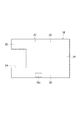
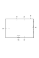
図2に示すように、架台16は、周縁部22と、該周縁部に設けられ、該周縁部の外方へ開放された切欠き部24とを有する平板である。架台16は、図2に示した例では、長方形であり、架台16の長さ方向(図2における左右方向)に隔てられた一端部26及び他端部28と、一端部26と他端部28との間にあって架台16の幅方向(図2における上下方向)に隔てられた2つの側部30とを有する。切欠き部24は一端部26にあって該一端部の前記長さ方向の外方へ開放されている。架台16は金属製である。
As shown in FIG. 2, the
架台16に傾斜計16aが取り付けられている。架台16から隔てられた地盤10の上の位置(図示せず)にディスプレー(図示せず)が配置されており、該ディスプレーは傾斜計16aに無線通信可能又は有線通信可能に接続されている。傾斜計16aは、水平面に対する架台16の傾斜度を測定し、該測定により得られた前記傾斜度に関するデータを前記ディスプレーへ送信する。前記ディスプレーは、傾斜計16aにより前記ディスプレーへ送信された前記データを受信し、該データを表示する。
An
位置14に架台16を配置した後、図1に示したように、架台16に掘削機32を載せる。掘削機32は、バックホウ、パワーショベル等である。掘削機32は、本体と、該本体に取り付けられたアームとを有し、該アームの先端部を前記本体へ引き寄せる方向に動かして斜面12を掘削する。架台16に掘削機32を載せるとき、該掘削機を、架台16から隔てられた地盤10の上の位置(図示せず)から架台16の上へ自走させてもよいし、クレーン18により掘削機32を架台16の上方から該架台へ吊り降ろしてもよい。架台16に掘削機32を載せた後、掘削機32を架台16に固定する。
After placing the
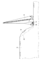
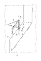
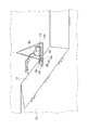
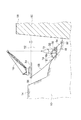
その後、図3に示すように、斜面12に複数のロックボルト34を水平方向に間隔を置いて固定する。その後、クレーン18により、掘削機32が載せられた架台16を吊り上げかつ位置14から斜面12へ移動させる。このとき、架台16が吊られた状態を維持しつつ、図4ないし6示すように、架台16の切欠き部24が斜面12に近接するように架台16を斜面12へ移動させる、すなわち架台16の一端部26が斜面12に接するように架台16を斜面12へ移動させる。その後、架台16を斜面12に固定する。このとき、各ロックボルト34に架台16の一端部26を結合する。
Thereafter, as shown in FIG. 3, the plurality of
架台16を吊り上げている間、架台16を水平な状態に維持するが、架台16を斜面12へ移動させたとき、架台16の一端部26が斜面12に引っ掛かって架台16が水平面に対して傾斜することがある。そこで、架台16が水平であることを確かめるため、架台16を斜面12へ移動させた後、傾斜計16aにより水平面に対する架台16の傾斜度を測定し、該測定により得られた前記傾斜度に関するデータを無線通信又は有線通信により傾斜計16aから前記ディスプレーへ送信し、該ディスプレーに前記データを表示する。前記測定の結果、架台16が水平面に対して傾斜している場合、クレーン18により架台16を斜面12から遠ざけ、再度、架台16を斜面12へ移動させ、傾斜計16aにより架台16の傾斜度を測定する。前記測定の結果、架台16が水平である場合、架台16を斜面12に固定する。
While the
架台16を斜面12に固定した後、図7に示すように、掘削機32により斜面12を掘削する。このとき、掘削機32を遠隔操作して斜面12を掘削する、すなわち斜面12を無人掘削する。斜面12を無人掘削する上記の例に代え、掘削機32に搭乗した操作員が該掘削機を操作して斜面12を掘削してもよい、すなわち斜面12を有人掘削してもよい。掘削機32により斜面12を掘削した後、図8に示すように、前記掘削により生じた土砂36を架台16の上から該架台の切欠き部24を経て斜面12に落とす。
After the
その後、ロックボルト34と架台16との結合を解除して斜面12への架台16の固定を解き、クレーン18により架台16を斜面12における既に掘削した位置から未だ掘削していない位置へ移動させる。その後、前記掘削していない位置で架台16を斜面12に固定し、掘削機32により斜面12を掘削する。
Thereafter, the coupling between the
掘削機32が載せられた架台16を吊り上げかつ位置14から斜面12へ移動させた後、掘削機32により斜面12を掘削するため、掘削機32を斜面12の下から該斜面における掘削位置へレール(図示せず)の上で移動させた後に前記掘削位置で掘削機32により斜面12を掘削する従来の場合のように斜面12に前記レールを敷設することを要しない。このため、斜面12への前記レールの敷設に多くの手間と時間とをかけることなく斜面12を効率的に掘削することができる。
After the
架台16の切欠き部24が斜面12に近接するように架台16を斜面12へ移動させた後、斜面12の掘削により生じた土砂36を架台16の上から切欠き部24を経て斜面12に落とすため、斜面12を掘削した掘削機32を旋回させることなく土砂36を架台16の上から斜面12に落とすことができる。このため、掘削機32の旋回に要する時間を省くことができ、斜面12の掘削をより効率的に行うことができる。
After moving the
斜面12へのロックボルト34の固定は、架台16に掘削機32を載せた後、架台16を斜面12へ移動させる前に行う上記の例に代え、架台16に掘削機32を載せる前に行ってもよいし、斜面12へ架台16を移動させた後、架台16を斜面12に固定する前に行ってもよい。
The
ロックボルト34の数は、複数である上記の例に代え、1本でもよい。また、斜面12への架台16の固定にロックボルト34を用いる上記の例に代え、アンカーボルトを用いてもよい。この場合、斜面12に少なくとも1本のアンカーボルト(図示せず)を固定し、その後、前記アンカーボルトに架台16を結合する。
The number of the
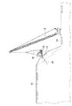
斜面12に複数のロックボルト34を固定した後、各ロックボルトに架台16を直接、結合する図4ないし6に示した例に代え、図9、10に示す例では、各ロックボルト34に架台16をワイヤーロープ38により結合する。図9、10に示した例では、斜面12の第1位置40へ移動させた架台16を斜面12に固定するが、これに先立ち、斜面12における第1位置40より低い高さにある第2位置42にロックボルト34を固定する。その後、架台16を斜面12に固定するとき、各ロックボルト34と架台16とをワイヤーロープ38で繋ぐ。
9 and 10, instead of the example shown in FIGS. 4 to 6, in which a plurality of
掘削機32により斜面12を掘削しているとき、架台16が掘削機32から上向き力を受けて浮き上がろうとすることがある。斜面12の第1位置40より低い高さにある第2位置42に固定されたロックボルト34と斜面12の第1位置40へ移動させた架台16とをワイヤーロープ38で繋ぐことにより、架台16が浮き上がるのを防止することができる。
When the
斜面12の第1位置40より低い高さにある第2位置42にロックボルト34を固定する図9、10に示した例に代え、第1位置40と同じ高さにある位置にロックボルト34を固定してもよいし、第1位置40より高い高さにある位置にロックボルト34を固定してもよい。斜面12に複数のロックボルト34を固定した後、各ロックボルトと架台16とをワイヤーロープ38で繋ぐ図9、10に示した例に代え、斜面12に1本のロックボルト34を固定した後、該ロックボルトと架台16とをワイヤーロープ38で繋いでもよい。
In place of the example shown in FIGS. 9 and 10 in which the
架台16の切欠き部24は、架台16の一端部26にあって該一端部の前記長さ方向の外方へ開放されている図2に示した例に代え、図11に示す例では、架台16の側部30にあって該側部の前記幅方向の外方へ開放されている。この場合、架台16を斜面12へ移動させるとき、架台16の側部30が斜面12に接するように架台16を斜面12へ移動させる、すなわち切欠き部24が斜面12に近接するように架台16を斜面12へ移動させる。なお、切欠き部24が架台16の一端部26にある場合及び切欠き部24が架台16の側部30にある場合のいずれも、切欠き部24は架台16の周縁部22に設けられている。
In the example shown in FIG. 11, the
架台16は、長方形である図2に示した例に代え、正方形でもよいし、円形、楕円形、三角形、五角形、他の多角形でもよい。いずれの場合においても、切欠き部24は架台16の周縁部に設けられており、架台16を斜面12へ移動させるとき、切欠き部24が斜面12に近接するように架台16を斜面12へ移動させる。
The
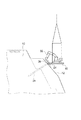
図12に示す例では、架台16の一端部26に2本の棒状部材44が前記幅方向に間隔を置いて固定されており、各棒状部材44は一端部26から前記長さ方向に外方へ伸びている。切欠き部24は架台16の一端部26における一方の棒状部材44が固定されている位置と他方の棒状部材44が固定されている位置との間にある。この場合、図13に示すように、架台16を斜面12に固定する前に該斜面に水平方向に間隔を置いて複数の穴(図示せず)を穿ち、架台16を斜面12に固定するとき、各棒状部材44を前記穴に挿入しかつ固定する。棒状部材44の数は、2本である図12に示した例に代え、1本でもよいし、3本以上でもよい。
In the example shown in FIG. 12, two rod-shaped
架台16の一端部26に2本の棒状部材44が固定されている図12に示した例に代え、図14に示す例では、架台16の一端部26に2つの鉤状部材46が前記幅方向に間隔を置いて取り付けられている。架台16を斜面12に固定するとき、各鉤状部材46を斜面12に係合させる。鉤状部材46の数は、2つである図14に示した例に代え、1つでもよいし、3以上でもよい。架台16の一端部26に鉤状部材46が取り付けられている図14に示した例に代え、架台16の一端部26に、斜面12を掴んで架台16を斜面12に固定する固定手段(図示せず)が取り付けられていてもよい。
In the example shown in FIG. 14 instead of the example shown in FIG. 12 in which the two rod-
図15に示す例では、架台16の周縁部22に切欠き部24が設けられている図2に示した例に代え、架台16の周縁部22に開口部48が設けられている。この場合、開口部48が斜面12に近接するように架台16を斜面12へ移動させた後、斜面12の掘削により生じた土砂36を架台16の上から開口部48を経て斜面12に落とす。開口部48は、図15に示した例では、架台16の一端部26に設けられているが、これに代え、架台16の側部30に設けられていてもよい。
In the example shown in FIG. 15, an
架台16の周縁部22に開口部48が設けられている図15に示した例に代え、図16に示すように、架台16の周縁部22に開口部48が設けられていなくてもよい。この場合、斜面12の掘削により生じた土砂36を架台16の上から架台16の側方を経て斜面12に落とす。
Instead of the example shown in FIG. 15 in which the
架台16は、金属製である図2に示した例に代え、木製でもよいし、鉄筋コンクリート製でもよい。位置14は、斜面12の下にある図1に示した例に代え、斜面12の上にあってもよい。斜面12の掘削は、地盤10に新たな法面20を形成するために行う図1に示した例に代え、土砂崩れにより法面20の上に崩れ落ちた土砂を除去するために行ってもよい。
The
斜面12は、図1に示した例では、陸上にあるが、これに代え、図17に示す例では、水中にある。図17に示した例では、斜面12は、ダム50により形成されたダム湖52の中にある。斜面12を掘削するとき、台船54をダム湖52に浮かせかつ湖岸56に係留し、台船54の上にクレーン18を配置する。
In the example shown in FIG. 1, the
台船54の上へのクレーン18の配置の前又は後に、斜面12から隔てられた地盤10の上の位置14に架台16を配置し、架台16に掘削機32を載せる。位置14は湖岸56の上にある。掘削機32は、いわゆる水中バックホウのような、水中での掘削作業を行うことができる掘削機である。
Before or after the placement of the
架台16に掘削機32を載せた後、斜面12に複数のロックボルト34を水平方向に間隔を置いて固定する。その後、クレーン18により、掘削機32が載せられた架台16を吊り上げかつ位置14から斜面12へ移動させる。その後、図18に示すように、架台16が吊られた状態を維持しつつ、架台16の切欠き部24が斜面12に近接するように架台16を斜面12へ移動させる。このとき、各ロックボルト34に架台16を結合する。
After placing the
架台16を斜面12へ移動させた後、架台16を斜面12に固定する前に、傾斜計16aにより水平面に対する架台16の傾斜度を測定し、該測定により得られた前記傾斜度に関するデータを無線通信又は有線通信により傾斜計16aから前記ディスプレーへ送信し、該ディスプレーに前記データを表示する。前記測定の結果、架台16が水平面に対して傾斜している場合、クレーン18により架台16を斜面12から遠ざけ、再度、架台16を斜面12へ移動させ、傾斜計16aにより架台16の傾斜度を測定する。前記測定の結果、架台16が水平である場合、架台16を斜面12に固定する。
After the
架台16を斜面12に固定した後、掘削機32により斜面12を掘削する。このとき、掘削機32を遠隔操作して斜面12を掘削してもよいし、掘削機32に搭乗した操作者が掘削機32を操作して斜面12を掘削してもよい。掘削機32により斜面12を掘削した後、該掘削により生じた土砂を架台16の上から切欠き部24を経て斜面12に落とす。
After fixing the
その後、ロックボルト34と架台16との結合を解除して斜面12への架台16の固定を解き、クレーン18により架台16を斜面12における既に掘削した位置から未だ掘削していない位置へ移動させる。その後、前記掘削していない位置で架台16を斜面12に固定し、掘削機32により斜面12を掘削する。
Thereafter, the coupling between the
掘削機32が載せられた架台16を吊り上げかつ位置14から斜面12へ移動させた後、掘削機32により斜面12を掘削するため、比較的大型である浚渫船(図示せず)をダム湖52へ搬入することを要せず、前記浚渫船をダム湖52へ搬入するための搬入路を確保できるか否かに拘わらず斜面12を掘削することができる。
After the
斜面12にロックボルト34を固定した後、該ロックボルトに、直接、架台16を結合する図18に示した例に代え、図9、10に示した例と同様に、ロックボルト34に架台16をワイヤーロープにより結合してもよい。
Instead of the example shown in FIG. 18 in which the
架台16は、図18に示した例では、架台16の一端部26に棒状部材44が固定されていないものであるが、これに代え、図12に示したように、一端部26に複数の棒状部材44が前記幅方向に間隔を置いて固定され、各棒状部材44が一端部26から前記長さ方向に外方へ伸びるものとすることができる。この場合、架台16を斜面12に固定する前に該斜面に水平方向に間隔を置いて複数の穴(図示せず)を穿ち、架台16を斜面12に固定するとき、各棒状部材44を前記穴に挿入しかつ固定する。
In the example shown in FIG. 18, the
架台16は、該架台の一端部26に2本の棒状部材44が固定されたものである図12に示した例に代え、図14に示したように、一端部26に2つの鉤状部材46が前記幅方向に間隔を置いて取り付けられたものとすることができる。この場合、架台16を斜面12に固定するとき、各鉤状部材46を斜面12に係合させる。架台16の一端部26に鉤状部材46が取り付けられている上記の例に代え、架台16の一端部26に、斜面12を掴んで架台16を斜面12に固定する固定手段(図示せず)が取り付けられていてもよい。
The
架台16は、該架台の周縁部22に切欠き部24が設けられたものである図18に示した例に代え、図15に示したように、周縁部22に開口部48が設けられたものとすることができる。この場合、架台16を斜面12へ移動させるとき、開口部48が斜面12に近接するように架台16を斜面12へ移動させ、掘削機32により斜面12を掘削した後、該掘削により生じた土砂を架台16の上から開口部48を経て斜面12に落とす。架台16は、周縁部22に開口部48が設けられたものである図15に示した例に代え、図16に示したように、架台16の周縁部22に開口部48が設けられていないものとすることができる。
The
斜面12は、ダム湖52の中にある図17に示した例に代え、自然の湖沼、河川又は海の中にあってもよい。位置14は、湖岸56の上にある図17に示した例に代え、ダム50の天端58の上にあってもよい。斜面12の掘削は、地盤10に新たな法面20を形成するために行ってもよいし、土砂崩れにより法面20の上に崩れ落ちた土砂を除去するために行ってもよいし、斜面12に堆積した土砂を除去するために行ってもよい。
The
図19に示す例では、架台16の一端部26に、架台16をロックボルト34に結合する結合手段60が取り付けられ、架台16の他端部28に穿孔機62が取り付けられている。斜面12が比較的軟弱である場合、架台16を斜面12へ移動させるとき、架台16の一端部26を斜面12に近付け、自穿孔式のロックボルト34により斜面12に孔(図示せず)を穿ち、該孔にロックボルト34を固定し、結合手段60により架台16をロックボルト34に結合する。他方、斜面12が比較的強固であり、自穿孔式のロックボルト34により斜面12に前記孔を穿つことが難しい場合、架台16を斜面12へ移動させるとき、まず、架台16の他端部28を斜面12に近付け、穿孔機62により斜面12に孔を穿ち、自穿孔式のロックボルト34を前記孔へ進入させ、該ロックボルトを前記孔に固定する。その後、架台16を回転させて架台16の一端部26を斜面12に近付け、結合手段60により架台16をロックボルト34に結合する。
In the example shown in FIG. 19, a coupling means 60 for coupling the
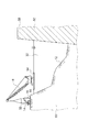
架台16を斜面12に固定するとき、架台16をロックボルト34に結合する図19に示した例に代え、図20に示す例では、架台16と斜面12から隔てられた地盤10の上の位置とをワイヤーロープ64、68を用いて繋ぐ。この場合、ワイヤーロープ64により架台16に連結された錘66をダム湖52の底に沈めてもよいし、架台16と湖岸56に係留された台船54とをワイヤーロープ68で連結してもよい。錘66をダム湖52の底に沈める場合、前記位置はダム湖52の底にあり、架台16はワイヤーロープ64と錘66とを介して前記位置に繋がれる。架台16と台船54とをワイヤーロープ68で連結する場合、前記位置は湖岸56にあり、架台16はワイヤーロープ68と台船54とを介して前記位置に繋がれる。掘削機32により斜面12を掘削している間に架台16が掘削機32から受ける外力の向きによっては、該外力により架台16が斜面12に対して回転しようとすることがある。ワイヤーロープ64、68は斜面12に対する架台16の回転を防止する。また、図19に示した例では、ロックボルト34は斜面12に対する架台16の回転を防止する。
When the
掘削機32は、架台16の上の本体70と、該本体に取り付けられたアーム72と、該アームの先端部に取り付けられたバケット74とを備える(図20)。掘削機32により斜面12を掘削するとき、掘削機32は、斜面12にバケット74を突き刺し、該バケットを本体70へ引き寄せる。このとき、架台16が掘削機32の本体70から外力を受けて、架台16の一端部26は、斜面12に押し付けられ、該斜面から反力を受ける。このため、架台16を斜面12に固定しなくても、架台16は掘削機32による斜面12の掘削時に斜面12から離れ難い。よって、掘削機32を斜面12へ移動させた後、掘削機32により斜面12を掘削する前に架台16を斜面12に固定する上記の例に代え、架台16を斜面12に固定しなくてもよい。
The
掘削機32のアーム72の前記先端部にバケット74が取り付けられている上記の例に代え、アーム72の前記先端部にブレーカー(図示せず)が取り付けられていてもよい。この場合、掘削機32により斜面12を掘削するとき、掘削機32は、前記ブレーカーを斜面12に突き刺し、該ブレーカーを本体70へ引き寄せる。このとき、架台16が掘削機32の本体70から外力を受けて、架台16の一端部26は、斜面12に押し付けられ、該斜面から反力を受ける。このため、架台16を斜面12に固定しなくても、架台16は掘削機32による斜面12の掘削時に斜面12から離れ難い。よって、掘削機32を斜面12へ移動させた後、掘削機32により斜面12を掘削する前に架台16を斜面12に固定する上記の例に代え、架台16を斜面12に固定しなくてもよい。
Instead of the above example in which the
10 地盤
12 斜面
14 位置
16 架台
22 周縁部
24 切欠き部
32 掘削機
34 ロックボルト
36 土砂
64、68 ワイヤーロープ
48 開口部
DESCRIPTION OF
Claims (7)
前記架台に掘削機を載せる第2ステップと、
前記掘削機が載せられた前記架台を吊り上げかつ前記位置から前記斜面へ移動させる第3ステップと、
前記掘削機により前記斜面を掘削する第4ステップとを含む、地盤の斜面を掘削する方法。 A first step of placing a gantry at a position above the ground separated from the ground slope;
A second step of placing an excavator on the platform;
A third step of lifting the platform on which the excavator is mounted and moving the platform from the position to the slope;
A method for excavating a ground slope, comprising: a fourth step of excavating the slope with the excavator.
前記第3ステップにおいて前記切欠き部又は前記開口部が前記斜面に近接するように前記架台を前記斜面へ移動させ、
前記第4ステップの後、前記斜面の掘削により生じた土砂を前記架台の上から前記切欠き部又は前記開口部を経て前記斜面に落とす、請求項1に記載の地盤の斜面を掘削する方法。 The mount is a flat plate having a peripheral edge and a notch or an opening provided on the peripheral edge and opened outward of the peripheral edge.
Moving the mount to the slope so that the notch or the opening is close to the slope in the third step;
2. The method for excavating a ground slope according to claim 1, wherein after the fourth step, earth and sand generated by excavation of the slope are dropped onto the slope through the notch or the opening from the top of the mount.
前記第5ステップにおいて前記ロックボルトに前記架台を結合する、請求項3に記載の地盤の斜面を掘削する方法。 Fixing at least one lock bolt to the slope before the fifth step;
The method for excavating a ground slope according to claim 3, wherein the mount is coupled to the rock bolt in the fifth step.
周縁部と、該周縁部に設けられた、該周縁部の外方へ開放された切欠き部又は開口部とを有する平板である、架台。 A base for an excavator used for excavation of a ground slope,
A pedestal that is a flat plate having a peripheral part and a notch part or an opening part provided at the peripheral part and opened outward from the peripheral part.
Priority Applications (1)
| Application Number | Priority Date | Filing Date | Title |
|---|---|---|---|
| JP2011065336A JP5619659B2 (en) | 2011-03-24 | 2011-03-24 | How to excavate the ground slope |
Applications Claiming Priority (1)
| Application Number | Priority Date | Filing Date | Title |
|---|---|---|---|
| JP2011065336A JP5619659B2 (en) | 2011-03-24 | 2011-03-24 | How to excavate the ground slope |
Publications (2)
| Publication Number | Publication Date |
|---|---|
| JP2012202043A true JP2012202043A (en) | 2012-10-22 |
| JP5619659B2 JP5619659B2 (en) | 2014-11-05 |
Family
ID=47183338
Family Applications (1)
| Application Number | Title | Priority Date | Filing Date |
|---|---|---|---|
| JP2011065336A Active JP5619659B2 (en) | 2011-03-24 | 2011-03-24 | How to excavate the ground slope |
Country Status (1)
| Country | Link |
|---|---|
| JP (1) | JP5619659B2 (en) |
Cited By (2)
| Publication number | Priority date | Publication date | Assignee | Title |
|---|---|---|---|---|
| CN106284363A (en) * | 2016-08-31 | 2017-01-04 | 中国电建集团贵阳勘测设计研究院有限公司 | High-efficiency dangerous rock mass artificial excavation method |
| CN108643198A (en) * | 2018-04-18 | 2018-10-12 | 中国十七冶集团有限公司 | Excavation of earthwork structure and its construction method between a kind of long and narrow foundation pit pile of ultra-deep |
Citations (6)
| Publication number | Priority date | Publication date | Assignee | Title |
|---|---|---|---|---|
| JPH06306867A (en) * | 1993-04-22 | 1994-11-01 | Toda Constr Co Ltd | Method and device for steep slope excavation |
| JPH07292963A (en) * | 1994-04-22 | 1995-11-07 | Toda Constr Co Ltd | Method and device for steep slope excavation |
| JPH11117308A (en) * | 1997-10-09 | 1999-04-27 | Tsutomu Kondo | Drilling device for surface of slope and fixing method thereof |
| JPH11148117A (en) * | 1997-11-17 | 1999-06-02 | Kumagai Gumi Co Ltd | Protection fence of road opening section |
| JPH11247572A (en) * | 1998-02-27 | 1999-09-14 | Raito Kogyo Co Ltd | Drilling equipment on slopes |
| JP2002167762A (en) * | 2000-11-30 | 2002-06-11 | Komatsu Ltd | Slope construction machine and slope construction method |
-
2011
- 2011-03-24 JP JP2011065336A patent/JP5619659B2/en active Active
Patent Citations (6)
| Publication number | Priority date | Publication date | Assignee | Title |
|---|---|---|---|---|
| JPH06306867A (en) * | 1993-04-22 | 1994-11-01 | Toda Constr Co Ltd | Method and device for steep slope excavation |
| JPH07292963A (en) * | 1994-04-22 | 1995-11-07 | Toda Constr Co Ltd | Method and device for steep slope excavation |
| JPH11117308A (en) * | 1997-10-09 | 1999-04-27 | Tsutomu Kondo | Drilling device for surface of slope and fixing method thereof |
| JPH11148117A (en) * | 1997-11-17 | 1999-06-02 | Kumagai Gumi Co Ltd | Protection fence of road opening section |
| JPH11247572A (en) * | 1998-02-27 | 1999-09-14 | Raito Kogyo Co Ltd | Drilling equipment on slopes |
| JP2002167762A (en) * | 2000-11-30 | 2002-06-11 | Komatsu Ltd | Slope construction machine and slope construction method |
Cited By (2)
| Publication number | Priority date | Publication date | Assignee | Title |
|---|---|---|---|---|
| CN106284363A (en) * | 2016-08-31 | 2017-01-04 | 中国电建集团贵阳勘测设计研究院有限公司 | High-efficiency dangerous rock mass artificial excavation method |
| CN108643198A (en) * | 2018-04-18 | 2018-10-12 | 中国十七冶集团有限公司 | Excavation of earthwork structure and its construction method between a kind of long and narrow foundation pit pile of ultra-deep |
Also Published As
| Publication number | Publication date |
|---|---|
| JP5619659B2 (en) | 2014-11-05 |
Similar Documents
| Publication | Publication Date | Title |
|---|---|---|
| JP7177554B2 (en) | Wall subsidence construction method | |
| JP5830423B2 (en) | Pile type offshore structure construction method and pile type offshore structure | |
| CN111893944B (en) | Environment-friendly submarine reef cleaning construction process | |
| CN104040079A (en) | Detachable positioning pile | |
| US20190292743A1 (en) | Anchor driving device | |
| JP5619659B2 (en) | How to excavate the ground slope | |
| JP5612980B2 (en) | Underwater drilling apparatus and underwater drilling method | |
| KR101861688B1 (en) | A Salvage Device of a Crane Bucket | |
| JP6586213B2 (en) | Construction method of jacket structure | |
| CN104878779A (en) | Covering-type silt prevention cover plate, silt prevention system and construction method of immersed tunnel gravel foundation bed | |
| JP2515888B2 (en) | Construction method of steel pipe pile for building offshore structure and its equipment | |
| KR20150054035A (en) | Jack up lig system | |
| JP2009209565A (en) | Pile attachment/detachment structure | |
| CN216056258U (en) | Inserted anchor damage prevention device for submarine cable | |
| KR20170070794A (en) | Shipping equipment for soil and rock underwater and Loading method by using it | |
| KR102093948B1 (en) | Grid typed plate and Method for consolidating dynamically and laying the surface evenly using the same | |
| JP2015169062A (en) | Pile press-in device | |
| JP6994778B2 (en) | Insertion device and method of H-shaped steel for earth retaining | |
| JP2012077566A (en) | Pneumatic caisson earth removal system | |
| CN223963090U (en) | Throwing device | |
| KR102262861B1 (en) | Quay structure reinforced pier type erection and method for reinforcement quay structure using pier type erection | |
| US20240133154A1 (en) | System and methods for underwater works | |
| JP4778460B2 (en) | Steel plate cell installation method and structure | |
| JP6235372B2 (en) | Drilling device and drilling method | |
| CN103161401A (en) | Ship for offshore operation |
Legal Events
| Date | Code | Title | Description |
|---|---|---|---|
| A621 | Written request for application examination |
Free format text: JAPANESE INTERMEDIATE CODE: A621 Effective date: 20140107 |
|
| RD03 | Notification of appointment of power of attorney |
Free format text: JAPANESE INTERMEDIATE CODE: A7423 Effective date: 20140107 |
|
| A977 | Report on retrieval |
Free format text: JAPANESE INTERMEDIATE CODE: A971007 Effective date: 20140829 |
|
| TRDD | Decision of grant or rejection written | ||
| A01 | Written decision to grant a patent or to grant a registration (utility model) |
Free format text: JAPANESE INTERMEDIATE CODE: A01 Effective date: 20140909 |
|
| A61 | First payment of annual fees (during grant procedure) |
Free format text: JAPANESE INTERMEDIATE CODE: A61 Effective date: 20140917 |
|
| R150 | Certificate of patent or registration of utility model |
Ref document number: 5619659 Country of ref document: JP Free format text: JAPANESE INTERMEDIATE CODE: R150 |
|
| S531 | Written request for registration of change of domicile |
Free format text: JAPANESE INTERMEDIATE CODE: R313531 |
|
| R350 | Written notification of registration of transfer |
Free format text: JAPANESE INTERMEDIATE CODE: R350 |
|
| S531 | Written request for registration of change of domicile |
Free format text: JAPANESE INTERMEDIATE CODE: R313531 |
|
| R350 | Written notification of registration of transfer |
Free format text: JAPANESE INTERMEDIATE CODE: R350 |