JP2012202071A - Step device for work machine - Google Patents
Step device for work machine Download PDFInfo
- Publication number
- JP2012202071A JP2012202071A JP2011066199A JP2011066199A JP2012202071A JP 2012202071 A JP2012202071 A JP 2012202071A JP 2011066199 A JP2011066199 A JP 2011066199A JP 2011066199 A JP2011066199 A JP 2011066199A JP 2012202071 A JP2012202071 A JP 2012202071A
- Authority
- JP
- Japan
- Prior art keywords
- handrail
- plate
- work machine
- scaffold plate
- step device
- Prior art date
- Legal status (The legal status is an assumption and is not a legal conclusion. Google has not performed a legal analysis and makes no representation as to the accuracy of the status listed.)
- Withdrawn
Links
- 238000010168 coupling process Methods 0.000 claims description 20
- 238000005859 coupling reaction Methods 0.000 claims description 20
- 230000008878 coupling Effects 0.000 claims description 19
- 239000002184 metal Substances 0.000 claims 1
- 239000000463 material Substances 0.000 description 8
- XEEYBQQBJWHFJM-UHFFFAOYSA-N Iron Chemical compound [Fe] XEEYBQQBJWHFJM-UHFFFAOYSA-N 0.000 description 4
- 238000005452 bending Methods 0.000 description 2
- 229910052742 iron Inorganic materials 0.000 description 2
- 230000000149 penetrating effect Effects 0.000 description 2
- 229910000831 Steel Inorganic materials 0.000 description 1
- 230000035515 penetration Effects 0.000 description 1
- 230000003014 reinforcing effect Effects 0.000 description 1
- 239000010959 steel Substances 0.000 description 1
Images




Landscapes
- Vehicle Step Arrangements And Article Storage (AREA)
Abstract
Description
本発明は、作業機械用ステップ装置に係り、特に、作業機械に対して折り畳み可能に構成された足場板を備えた作業機械用ステップ装置における、足場板に対する手摺りの取付構造に関する。 The present invention relates to a step device for a work machine, and more particularly, to a structure for attaching a handrail to a scaffold plate in a step device for a work machine that includes a scaffold plate configured to be foldable with respect to the work machine.
例えばテレスコ式クラムシェルのような前後スライド式可動キャブを備えた作業機械には、運転室へのオペレータの乗り込みを容易かつ安全なものにするため、下部走行体の中央部から運転室まで延びるステップ装置が備えられるものがある。このステップ装置は、運転室を有する上部旋回体に取り付けられ、運転室の側方部分に張り出して設置されるため、このままの状態では道路交通法に規定されるトレーラによる輸送時の車幅制限を超えてしまう場合がある。 For example, in a work machine equipped with a forward / backward sliding movable cab such as a telescopic clamshell, a step extending from the center of the lower traveling body to the cab to make it easy and safe for the operator to enter the cab Some devices are equipped. Since this step device is attached to the upper turning body having the cab and is installed overhanging the side part of the cab, the vehicle width limitation at the time of transportation by the trailer stipulated in the Road Traffic Act is maintained in this state. It may exceed.
従来、このような問題に対処するため、足場板と、足場板の外側辺より起立された手摺りとから構成される作業機械用ステップ装置に関し、足場板をその長さ方向の複数個所で支持する複数のアームの一端を水平面内で旋回可能であるように上部旋回体に取り付け、かつ足場板をアームの上面に対して起伏可能に取り付け、更には、手摺りの支柱をアームの先端部に回転可能に取り付けたものが提案されている(例えば、特許文献1参照。)。この作業機械用ステップ装置は、アームを上部旋回体の側面に対して垂直外向きに張り出し、この張り出されたアームの上面に足場板を水平に倒伏し、かつ手摺りをアームの先端部から垂直に起立させることにより、オペレータが歩行可能な使用状態となる。また、この状態から、アームの長さ方向の一側辺を回動中心として足場板を垂直に起立し、アームを上部旋回体の側面に沿う方向に旋回することにより、起立された足場板とアームの先端部に垂直に起立されている手摺りとが互いに厚さ方向に重なり合って、上部旋回体の側面部分に配置される格納状態となる。 Conventionally, in order to cope with such a problem, a step device for a work machine composed of a scaffold plate and a handrail raised from the outer side of the scaffold plate, the scaffold plate is supported at a plurality of positions in the length direction. Attach one end of multiple arms to the upper swivel so that it can swivel in a horizontal plane, and attach the scaffolding plate to the upper surface of the arm so that it can be raised and lowered. The thing attached so that rotation is possible is proposed (for example, refer to patent documents 1). In this work machine step device, the arm is projected vertically outward with respect to the side surface of the upper swing body, the scaffolding plate is laid horizontally on the upper surface of the projected arm, and the handrail is extended from the tip of the arm. By standing upright, the operator can walk. Also, from this state, the scaffold plate is erected vertically with the one side in the length direction of the arm as the rotation center, and the arm is pivoted in the direction along the side surface of the upper swing body, A handrail standing perpendicularly to the tip of the arm overlaps with each other in the thickness direction, and is placed in a side state of the upper revolving unit.
本例の作業機械用ステップ装置は、格納することにより、上部旋回体からのステップ装置の張り出し量を小さくすることができ、これを備えた作業機械のトレーラ輸送を可能にすることができる。 By storing the step device for the working machine of this example, the amount of the step device protruding from the upper swing body can be reduced, and the trailer transportation of the working machine including the step device can be enabled.
しかしながら、本例の作業機械用ステップ装置は、格納状態において、足場板と手摺りが互いに厚さ方向に重なり合って上部旋回体の側面部分に配置されるので、上部旋回体からのステップ装置の突出量を十分に小さくすることができず、さらなる改善の余地がある。また、ステップ装置を使用状態から格納状態に移行する際、アーム、足場板及び手摺りが上部旋回体の前方位置から後方位置に移動するので、上部旋回体上のステップ装置の移動範囲には、例えばオペレータの安全を確保するための手摺棒などの他の部材を配置することができない。 However, in the working machine step device of the present example, in the retracted state, the scaffold plate and the handrail overlap each other in the thickness direction and are disposed on the side surface portion of the upper swing body, so that the step device protrudes from the upper swing body. The amount cannot be made sufficiently small, and there is room for further improvement. Further, when the step device shifts from the use state to the retracted state, the arm, the scaffolding plate and the handrail move from the front position of the upper swing body to the rear position. For example, other members such as handrail bars for ensuring the safety of the operator cannot be arranged.
本発明は、このような従来技術の問題点に鑑みてなされたものであり、その目的とするところは、足場板の側方部分と前方部分とに手摺りを備えた作業機械用ステップ装置であって、格納状態において作業機械の側面からの突出量を小さくすることができる作業機械用ステップ装置を提供することにある。 The present invention has been made in view of such problems of the prior art, and an object thereof is a step device for a working machine provided with handrails on a side portion and a front portion of a scaffold plate. Another object of the present invention is to provide a work machine step device that can reduce the amount of protrusion from the side surface of the work machine in the retracted state.
本発明は、前記の課題を解決するため、作業機械の運転室の側面に沿って取り付けられた足場板と、当該足場板の外側辺部より起立された第1手摺りと、前記足場板の前端部より起立された第2手摺りを備えた作業機械用ステップ装置において、前記足場板は、前記運転室の前端よりも前方に延在して設けられ、その一側辺部を回動中心として、水平状態と垂直状態との間で起伏可能に前記作業機械の側面に取り付けられ、前記第1手摺りは、水平状態に保持された前記足場板に対して、その下端部を回動中心として、水平状態と垂直状態との間で起伏可能に取り付けられ、前記第2手摺りは、その下端部が前記足場板の前端部に固定されており、使用状態では、前記足場板が水平状態に保持されて、当該足場板の外側辺部と前端部とに前記第1手摺りと前記第2手摺りが垂直に起立され、格納状態では、前記足場板及び前記第1手摺りが一直線に連結された状態で、前記作業機械の側面に沿って垂直に起立されると共に、前記第2手摺りが前記作業機械の前方に配置されることを特徴とする
かかる構成によると、格納状態において、足場板と第1手摺りとを上下に連結した状態で作業機械の側面に沿って垂直に起立するので、足場板と第1手摺りとを厚さ方向に重なり合わせる場合に比べて、上部旋回体からのステップ装置の突出量を小さくすることができる。また、足場板及び第1手摺りを上部旋回体に対する足場板の取付位置において上方に移動するだけであるので、足場板及び第1手摺りを上部旋回体の前方位置から後方位置に移動する場合のように、他の部材の障害とならず、作業機械の設計の自由度を確保することができる。さらに、格納状態において、第2手摺りを作業機械の前方に配置するので、第2手摺りが作業機械と干渉せず、足場板の側方と前方とに第1及び第2の手摺りを備えるステップ装置の格納を容易に行うことができる。
In order to solve the above problems, the present invention provides a scaffold plate attached along a side surface of a cab of a work machine, a first handrail erected from an outer side portion of the scaffold plate, and the scaffold plate. In the work machine step device provided with the second handrail erected from the front end portion, the scaffold plate is provided to extend forward from the front end of the cab, and one side portion of the scaffold plate is pivotally centered. The first handrail is attached to the side surface of the work machine so as to be able to undulate between a horizontal state and a vertical state, and the first handrail is pivoted at the lower end with respect to the scaffold plate held in the horizontal state. The second handrail has a lower end fixed to the front end of the scaffold plate, and in use, the scaffold plate is in a horizontal state. Held on the outer side and front end of the scaffold plate One handrail and the second handrail are erected vertically, and in the retracted state, the scaffolding plate and the first handrail are erected vertically along the side surface of the work machine with the straight line connected. In addition, the second handrail is disposed in front of the work machine. According to such a configuration, in the retracted state, the side surface of the work machine is connected with the scaffold plate and the first handrail vertically. Therefore, the amount of protrusion of the step device from the upper swing body can be reduced as compared with the case where the scaffolding plate and the first handrail are overlapped in the thickness direction. Further, when the scaffold plate and the first handrail are merely moved upward at the mounting position of the scaffold plate with respect to the upper swing body, the scaffold plate and the first handrail are moved from the front position to the rear position of the upper swing body. As described above, the degree of freedom in designing the work machine can be ensured without obstructing other members. Furthermore, since the second handrail is disposed in front of the work machine in the retracted state, the second handrail does not interfere with the work machine, and the first and second handrails are placed on the side and front of the scaffolding plate. The step device provided can be easily stored.
また本発明は、前記構成の作業機械用ステップ装置において、前記第1手摺りは、複数本の支柱とこれら複数本の支柱を連結する1乃至複数本の横桟とから構成され、前記足場板と前記第1手摺りの支柱とは、前記足場板に固定された第1手摺り連結金具を介して連結されていて、前記第1手摺り連結金具と前記第1手摺りの支柱とは、連結ピンを介して回動自在に連結され、前記第1手摺りは、前記第1手摺り連結金具及び前記第1手摺りのうちのいずれか一方に形成された係合突起といずれか他方に形成された突起係合孔とを係合し合うことにより、使用状態及び格納状態に対応する所定の位置に保持されることを特徴とする。 Further, the present invention is the work machine step device having the above-described configuration, wherein the first handrail is composed of a plurality of support posts and one or more cross rails connecting the plurality of support posts, and the scaffold plate And the first handrail strut are connected via a first handrail connecting bracket fixed to the scaffold plate, and the first handrail connecting bracket and the first handrail strut are: The first handrail is pivotally connected via a connecting pin, and the first handrail is connected to an engagement protrusion formed on one of the first handrail connecting bracket and the first handrail and to the other. By engaging the formed projection engaging holes with each other, they are held at predetermined positions corresponding to the use state and the storage state.
かかる構成によると、第1手摺り連結金具と第1手摺りの支柱とを連結ピンを介して回動自在に連結し、第1手摺り連結金具及び第1手摺りのうちのいずれか一方に形成された係合突起といずれか他方に形成された突起係合孔とを係合し合うことによって足場板に対する第1手摺りの設定を行うので、係合突起と突起係合孔との係合力よりも大きな力を第1手摺りに加えることにより、第1手摺りを足場板に対して使用状態から格納状態に、又は格納状態から使用状態に変更することができ、ステップ装置の取り扱いを容易なものにすることができる。 According to such a configuration, the first handrail connecting bracket and the first handrail support column are rotatably connected via the connecting pin, and either the first handrail connecting bracket or the first handrail is connected. Since the first handrail with respect to the scaffolding plate is set by engaging the formed engaging protrusion with the protrusion engaging hole formed on the other, the engagement protrusion and the protrusion engaging hole are engaged with each other. By applying a force larger than the resultant force to the first handrail, the first handrail can be changed from the use state to the storage state or from the storage state to the use state with respect to the scaffolding plate, and the handling of the step device can be performed. It can be easy.
また本発明は、前記構成の作業機械用ステップ装置において、前記作業機械と前記足場板とは、作業機械の側面に固定された足場板連結金具を介して連結され、前記足場板連結金具と前記足場板とは、連結ピンを介して回動自在に連結されていて、前記足場板は、前記足場板連結金具の一部と前記足場板の一部とを突き当てることにより、使用状態に対応する所定の位置に保持されることを特徴とする。 Further, the present invention is the work machine step device having the above-described configuration, in which the work machine and the scaffold plate are coupled via a scaffold plate coupling bracket fixed to a side surface of the work machine, and the scaffold plate coupling bracket and the scaffold plate The scaffolding plate is pivotally connected via a connecting pin, and the scaffolding plate is adapted to the state of use by abutting a part of the scaffolding plate coupling bracket and a part of the scaffolding plate. It is characterized by being held at a predetermined position.
かかる構成によると、足場板連結金具の一部と足場板の一部とを突き当てることにより、足場板を使用状態に対応する所定の位置に保持するので、オペレータが乗っても足場板がそれ以上回動せず、安定性に優れた強固な足場とすることができる。 According to such a configuration, the scaffold plate is held in a predetermined position corresponding to the use state by abutting a part of the scaffold plate coupling bracket and a part of the scaffold plate, so that the scaffold plate does not move even if the operator gets on it. It is possible to provide a strong scaffold that does not rotate and has excellent stability.
本発明の作業機械用ステップ装置は、格納状態において、足場板と第1手摺りとを上下に連結した状態で作業機械の側面に沿って垂直に起立するので、上部旋回体からのステップ装置の突出量を小さくすることができる。また、足場板及び第1手摺りを上部旋回体に対する足場板の取付位置において上方に移動するだけであるので、周辺に配置された他の部材と干渉しづらい。 Since the work machine step device of the present invention stands vertically along the side surface of the work machine with the scaffold plate and the first handrail connected vertically in the retracted state, The amount of protrusion can be reduced. Further, since the scaffolding plate and the first handrail are merely moved upward at the mounting position of the scaffolding plate with respect to the upper swing body, it is difficult to interfere with other members arranged in the vicinity.
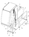
図1及び図2において、符号1は作業機械の上部旋回体、符号2は上部旋回体1上に設置された作業機械の運転室、符号3,4は運転室2に備えられた固定手摺り、符号11は上部旋回体1の側面部に取り付けられたステップ装置を示している。なお、図示は省略するが、上部旋回体1は、下部走行体の上部に旋回可能に取り付けられており、自走できるようになっている。また、運転室2を介してステップ装置11の反対側には、作業用のフロント部材が備えられており、フロント部材を駆動することによって所要の作業を実行できるようになっている。
1 and 2,
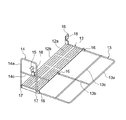
図1〜図5に示すように、ステップ装置11は、オペレータがその上を歩く足場板12と、足場板12の外側辺部より起立された第1手摺り13と、足場板12の前端部より起立された第2手摺り14と、上部旋回体1に足場板12を取り付ける足場板連結金具15と、足場板12に第1手摺り13を取り付ける第1手摺り連結金具16と、足場板12に第2手摺り14を取り付ける第2手摺り固定金具17を備えて構成されている。
As shown in FIGS. 1 to 5, the
足場板12は、表面に滑り止め用の小突起が多数形成された細長い長方形の鉄板12aと、その周囲に取り付けられた補強用の枠体12bとをもって形成されており、図1に示すように、運転室2の側方部分に取り付けたとき、その前端部が運転室2の前端よりも前方まで延在する長さに形成されている。このように、足場板12の前端部を運転室2の前端よりも前方まで延在させると、図2に示すように、運転室2への乗降に際して、オペレータが運転室2に設けられたドア2aの開閉端よりも前方部分に立つことができるので、ドア2aを全開状態まで開かなくても運転室2への乗降が可能になる。その結果、足場板12の幅を運転席2へのオペレータの乗降が可能な大きさに抑制できるので、ステップ装置11の計量化を図ることができ、人力による格納が容易になる。枠体12bの所定位置には、足場板連結金具15、第1手摺り連結金具16及び第2手摺り連結金具17が取り付けられる。
The
第1手摺り13は、1本の管材の両端部を同一方向に折り曲げることによって下向きコの字形に形成された第1手摺り本体13aと、第1手摺り本体13aを構成する管材と同一の管材をもって形成され、第1手摺り本体13aの水平部の中央位置より垂設された縦部材13bと、同じく第1手摺り本体13aを構成する管材と同一の管材をもって形成され、第1手摺り本体13aの各垂直部と縦部材13bとを、それらの長さ方向の中央部分で連結する横桟13cとから構成される。第1手摺り本体13aの各垂直部と縦部材13bは、第1手摺り13の支柱を構成するもので、その先端部は、後述するように、第1手摺り連結金具16を介して、足場板12に連結される。なお、第1手摺り本体13a、縦部材13b及び横桟13cは、それぞれ異なる管材をもって形成することもできる。
The
第2手摺り14は、1本の管材の両端部を同一方向に折り曲げることによって下向きコの字形に形成された第2手摺り本体14aと、第2手摺り本体14aを構成する管材と同一の管材をもって形成され、第2手摺り本体14aの各垂直部を、それらの長さ方向の中央部分で連結する横桟14cとから構成される。第2手摺り本体14aの各垂直部は、第2手摺り14の支柱を構成するもので、その先端部は、後述するように、第2手摺り連結金具17を介して、足場板12に連結される。なお、第1手摺り本体13aと第2手摺り本体14aとは、ほぼ全高が等しくなるように形成される。また、第2手摺り本体14aと横桟14cは、それぞれ異なる管材をもって形成することもできる。
The
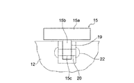
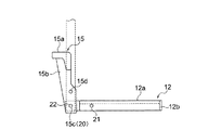
足場板連結金具15は、図3、図4、図6及び図7に示すように、L型鋼をもって形成された固定部15aと、固定部15aから垂設された板状の足場板取付部材15bとからなり、固定部15aは、ボルト18を用いて上部旋回体1の側面に取り付けられる。足場板取付部材15bの下端部には、図7に示すように、足場板12を回動自在にピン結合するための連結ピン貫通孔15cが開設されると共に、その垂直上方には、突起係合孔15dが開設されている。これに対して、足場板12の枠体12bには、図6に示すように、足場板取付部材15bを内装可能な凹部19が形成されており、その一端には、図7に示すように、足場板取付部材15bに開設された連結ピン貫通孔15cに対応する連結ピン貫通孔20が開設されると共に、足場板取付部材15bに開設された突起係合孔15dと対応する位置には、凹部19の内方に突出する係合突起21が形成されている。
As shown in FIGS. 3, 4, 6, and 7, the scaffolding
上部旋回体1(足場板連結金具15)と足場板12とは、連結ピン貫通孔15c,20に連結ピン22を貫通することにより、回動自在に連結される。そして、足場板12を水平位置まで回動した場合には、図7に実線で示すように、足場板取付部材15bの端部が凹部19の底面に突き当たるため、これ以上の足場板12の回動が防止され、オペレータの歩行が可能な使用状態となる。また、連結ピン22を中心として足場板12を垂直上方に回動すると、図7に破線で示すように、足場板取付部材15bに開設された突起係合孔15dに、足場板12に設けられた係合突起21が係合し、搬送中に振動が作用しても容易に倒伏しない格納状態となる。
The upper swing body 1 (scaffold plate coupling bracket 15) and the
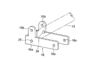
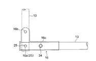
第1手摺り連結金具16は、図8に示すように、側面から見た形状がL字形で、平面から見た形状が第1手摺り13の支柱を内装可能なコの字形に形成されており、コの字形の底面部分が足場板12を構成する枠体12bの外面に固定される。L字形部の角部には、足場板12を回動自在にピン結合するための連結ピン貫通孔16aが開設されると共に、L字形の各先端部には、突起係合孔16b,16cが開設されている。これに対して、第1手摺り13を構成する各支柱の先端部には、図9に示すように、第1手摺り連結金具16に開設された連結ピン貫通孔16aに対応する連結ピン貫通孔23が開設されると共に、第1手摺り連結金具16に開設された突起係合孔16b,16cと対応する位置には、支柱の外方に突出する係合突起24が形成されている。
As shown in FIG. 8, the first
足場板12(第1手摺り連結金具16)と第1手摺り13とは、連結ピン貫通孔16a,22に連結ピン25を貫通することにより、回動自在に連結される。そして、第1手摺り13を垂直位置まで回動した場合には、図3に示すように、第1手摺り連結金具16に開設された突起係合孔16bに、第1手摺り13を構成する各支柱に形成された係合突起24が係合され、足場板12に対して第1手摺り13が安定に起立した使用状態となる。この状態から、連結ピン25を中心として第1手摺り13を水平方向に回動すると、第1手摺り連結金具16に開設された突起係合孔16cに、第1手摺り13を構成する各支柱に形成された係合突起24が係合され、図4及び図5に示すように、足場板12と第1手摺り13とが同一面上に並列された格納状態となる。
The scaffolding plate 12 (first handrail connecting bracket 16) and the
第2手摺り固定金具17は、第2手摺り14を構成する各支柱を内装可能な円筒部17aと、該円筒部17aの両端から水平に拡開された平面部17bとから構成されており、平面部17bが足場板12の前端部分に固定されている。第2手摺り14は、各支柱を第2手摺り固定金具17の円筒部17a内に挿入し、円筒部17aの外部からねじ26を螺合することによって、足場板12に固定される。
The second
以下、上述のように構成された作業機械用ステップ装置の使用時の状態と、格納時の状態とについて説明する。 Hereinafter, the state at the time of use of the step machine for work machines configured as described above and the state at the time of storage will be described.
使用状態においては、図3に示すように、足場板12が水平位置に保持され、第1及び第2の手摺り13,14が足場板12に対して垂直に起立されている。これによりオペレータは、足場板12上を歩いて、運転室2への乗車又は運転室2〜の下車を行うことができる。ステップ装置11を使用状態から格納状態にするためには、まず、図4に示すように、連結ピン24を中心として第1手摺り13を水平方向に回動し、足場板12と第1手摺り13とを同一面上に並列させる。次いで、図5に示すように、連結ピン21を中心として足場板12を第1手摺り13と共に垂直上方に回動する。このとき、第2手摺り14は、上部旋回体1(運転室2)の前方に配置される。
In the state of use, as shown in FIG. 3, the
本実施形態に係る作業機械用ステップ装置11は、格納状態において、足場板12と第1手摺り13とを上下に連結した状態で上部旋回体1(運転室2)の側面に沿って垂直に起立するので、上部旋回体1(運転室2)からのステップ装置11の突出量を小さくすることができ、トレーラ移送を円滑に行うことができる。また、足場板12及び第1手摺り13を上部旋回体1に対する足場板12の取付位置において上方に移動するだけであるので、運転室の外壁に取り付けられた固定手摺り3,4とステップ装置11とが干渉せず、作業機械の設計の自由度を確保することができる。さらに、格納状態において、第2手摺り14を上部旋回体1(運転室2)の前方に配置するので、第2手摺り14が作業機械と干渉せず、足場板12の側方と前方とに第1及び第2の手摺り13,14を備えるステップ装置11の格納を容易に行うことができる。
In the retracted state, the work
なお、本発明の要旨は、格納状態において、足場板12及び第1手摺り13を上下に連結して上部旋回体1(運転室2)の側面部分に配置することにあるのであって、足場板連結金具16、第1手摺り連結金具16及び第2手摺り連結金具17については、上述のものに限定される訳ではなく、目的に合致した適宜のものを用いることができる。
The gist of the present invention resides in that the
本発明は、テレスコ式クラムシェルのような前後スライド式可動キャブを備えた作業機械のステップ装置に利用できる。 INDUSTRIAL APPLICATION This invention can be utilized for the step apparatus of the working machine provided with the back-and-forth slide type movable cab like a telescopic clam shell.
1 作業機械の上部旋回体
2 作業機械の運転室
3,4 固定手摺り
11 作業機械用ステップ装置
12 足場板
12a 鉄板
12b 枠体
13 第1手摺り
13a 第1手摺り本体
13b 縦部材
13c 横桟
14 第2手摺り
14a 第2手摺り本体
14c 横桟
15 足場板連結金具
15a 固定部
15b 足場板取付部材
15c 連結ピン貫通孔
15d 突起係合孔
16 第1手摺り連結金具
16a 連結ピン貫通孔
16b,16c 突起係合孔
17 第2手摺り固定金具
17a 円筒部
17b 平面部
18 ボルト
19 凹部
20 連結ピン貫通孔
21 係合突起
22 連結ピン
23 連結ピン貫通孔
24 係合突起
25 連結ピン
26 ねじ
DESCRIPTION OF
Claims (3)
前記足場板は、前記運転室の前端よりも前方に延在して設けられ、その一側辺部を回動中心として、水平状態と垂直状態との間で起伏可能に前記作業機械の側面に取り付けられ、前記第1手摺りは、水平状態に保持された前記足場板に対して、その下端部を回動中心として、水平状態と垂直状態との間で起伏可能に取り付けられ、前記第2手摺りは、その下端部が前記足場板の前端部に固定されており、
使用状態では、前記足場板が水平状態に保持されて、当該足場板の外側辺部と前端部とに前記第1手摺りと前記第2手摺りが垂直に起立され、格納状態では、前記足場板及び前記第1手摺りが一直線に連結された状態で、前記作業機械の側面に沿って垂直に起立されると共に、前記第2手摺りが前記作業機械の前方に配置されることを特徴とする作業機械用ステップ装置。 A scaffolding plate attached along the side of the operator's cab of the work machine, a first handrail raised from the outer side of the scaffolding plate, and a second handrail raised from the front end of the scaffolding plate In a working machine step device,
The scaffolding plate is provided to extend forward from the front end of the cab, and the side of the work machine can be undulated between a horizontal state and a vertical state with one side portion as a rotation center. The first handrail is attached to the scaffolding plate held in a horizontal state so that it can be raised and lowered between a horizontal state and a vertical state with the lower end portion as a rotation center. The handrail has its lower end fixed to the front end of the scaffold plate,
In the use state, the scaffold plate is held in a horizontal state, and the first handrail and the second handrail stand upright on the outer side portion and the front end portion of the scaffold plate. With the plate and the first handrail connected in a straight line, the plate and the first handrail are erected vertically along the side surface of the work machine, and the second handrail is disposed in front of the work machine. A step device for a working machine.
Priority Applications (1)
| Application Number | Priority Date | Filing Date | Title |
|---|---|---|---|
| JP2011066199A JP2012202071A (en) | 2011-03-24 | 2011-03-24 | Step device for work machine |
Applications Claiming Priority (1)
| Application Number | Priority Date | Filing Date | Title |
|---|---|---|---|
| JP2011066199A JP2012202071A (en) | 2011-03-24 | 2011-03-24 | Step device for work machine |
Publications (1)
| Publication Number | Publication Date |
|---|---|
| JP2012202071A true JP2012202071A (en) | 2012-10-22 |
Family
ID=47183360
Family Applications (1)
| Application Number | Title | Priority Date | Filing Date |
|---|---|---|---|
| JP2011066199A Withdrawn JP2012202071A (en) | 2011-03-24 | 2011-03-24 | Step device for work machine |
Country Status (1)
| Country | Link |
|---|---|
| JP (1) | JP2012202071A (en) |
Cited By (4)
| Publication number | Priority date | Publication date | Assignee | Title |
|---|---|---|---|---|
| JP2016135975A (en) * | 2015-01-23 | 2016-07-28 | 住友建機株式会社 | Shovel |
| CN105986589A (en) * | 2015-03-20 | 2016-10-05 | 住友建机株式会社 | Small revolving excavator |
| JP2018025030A (en) * | 2016-08-10 | 2018-02-15 | 日立建機株式会社 | Work machine |
| JP6321888B1 (en) * | 2016-12-28 | 2018-05-09 | 株式会社小松製作所 | Work vehicle |
-
2011
- 2011-03-24 JP JP2011066199A patent/JP2012202071A/en not_active Withdrawn
Cited By (6)
| Publication number | Priority date | Publication date | Assignee | Title |
|---|---|---|---|---|
| JP2016135975A (en) * | 2015-01-23 | 2016-07-28 | 住友建機株式会社 | Shovel |
| CN105986589A (en) * | 2015-03-20 | 2016-10-05 | 住友建机株式会社 | Small revolving excavator |
| JP2018025030A (en) * | 2016-08-10 | 2018-02-15 | 日立建機株式会社 | Work machine |
| JP6321888B1 (en) * | 2016-12-28 | 2018-05-09 | 株式会社小松製作所 | Work vehicle |
| WO2018123007A1 (en) * | 2016-12-28 | 2018-07-05 | 株式会社小松製作所 | Utility vehicle |
| US10577775B2 (en) | 2016-12-28 | 2020-03-03 | Komatsu Ltd. | Work vehicle |
Similar Documents
| Publication | Publication Date | Title |
|---|---|---|
| EP2130979A2 (en) | Step apparatus for heavy construction equipment and tree harvester having leveling system | |
| JP5300587B2 (en) | Portable work table moving device | |
| JP3892710B2 (en) | Method and apparatus for attaching pipe structure to temporary scaffold | |
| JP5377728B1 (en) | Crane front attachment assembly method and apparatus | |
| JP5791435B2 (en) | Aerial work basket | |
| JP6520591B2 (en) | Cab guard equipped to the crane | |
| JP2016135975A (en) | Shovel | |
| JP5307760B2 (en) | Side step device for work equipment | |
| JP4500462B2 (en) | Scaffolding equipment for viaduct installation and method for installation | |
| JP2003041584A (en) | Pile driver and leader bringing-down method for pile driver | |
| JP2013253394A (en) | Step structure for construction machine | |
| JP2011057399A (en) | Work bench of vehicle for high lift work | |
| JP2002038711A (en) | Tread supporting structure in temporary scaffold and temporary scaffold | |
| JP7023581B2 (en) | Pile driver | |
| JP4770417B2 (en) | Construction machinery platform | |
| JP4719517B2 (en) | Exterior wall climbing apparatus and exterior wall climbing method | |
| JP5404067B2 (en) | Suspension device for aerial work platforms | |
| JP2017012416A (en) | Flat body with fall prevention device | |
| JP2003192272A (en) | Construction machinery | |
| JP7626732B2 (en) | Lifting platform workbench | |
| JP2003120033A (en) | Concrete hose ground connecting device | |
| JP5778943B2 (en) | Aerial work platform | |
| JP5877531B1 (en) | Truck carrier and truck carrier safety equipment | |
| JP2015010416A (en) | Pile driver | |
| JP4044874B2 (en) | Safety handrail |
Legal Events
| Date | Code | Title | Description |
|---|---|---|---|
| A300 | Withdrawal of application because of no request for examination |
Free format text: JAPANESE INTERMEDIATE CODE: A300 Effective date: 20140603 |