JP2012202811A - Abrasion testing method of rubber material or the like and abrasion testing device used therefor - Google Patents
Abrasion testing method of rubber material or the like and abrasion testing device used therefor Download PDFInfo
- Publication number
- JP2012202811A JP2012202811A JP2011067499A JP2011067499A JP2012202811A JP 2012202811 A JP2012202811 A JP 2012202811A JP 2011067499 A JP2011067499 A JP 2011067499A JP 2011067499 A JP2011067499 A JP 2011067499A JP 2012202811 A JP2012202811 A JP 2012202811A
- Authority
- JP
- Japan
- Prior art keywords
- wear
- test piece
- test
- rubber material
- test pieces
- Prior art date
- Legal status (The legal status is an assumption and is not a legal conclusion. Google has not performed a legal analysis and makes no representation as to the accuracy of the status listed.)
- Withdrawn
Links
- 238000012360 testing method Methods 0.000 title claims abstract description 174
- 239000000463 material Substances 0.000 title claims abstract description 69
- 229920001971 elastomer Polymers 0.000 title claims abstract description 32
- 239000005060 rubber Substances 0.000 title claims abstract description 32
- 238000005299 abrasion Methods 0.000 title abstract description 17
- 238000000034 method Methods 0.000 claims abstract description 8
- 238000010998 test method Methods 0.000 claims description 13
- 239000007921 spray Substances 0.000 claims description 8
- 238000005507 spraying Methods 0.000 claims description 6
- 239000012254 powdered material Substances 0.000 claims description 3
- 238000011156 evaluation Methods 0.000 abstract description 4
- 239000003082 abrasive agent Substances 0.000 abstract 3
- 239000000428 dust Substances 0.000 abstract 1
- 238000002347 injection Methods 0.000 description 41
- 239000007924 injection Substances 0.000 description 41
- 239000000126 substance Substances 0.000 description 10
- 238000007664 blowing Methods 0.000 description 5
- 239000008187 granular material Substances 0.000 description 4
- 230000000052 comparative effect Effects 0.000 description 3
- 239000004744 fabric Substances 0.000 description 2
- 238000005259 measurement Methods 0.000 description 2
- 239000004033 plastic Substances 0.000 description 2
- 239000000843 powder Substances 0.000 description 2
- 229920002725 thermoplastic elastomer Polymers 0.000 description 2
- 229910000831 Steel Inorganic materials 0.000 description 1
- 229920006311 Urethane elastomer Polymers 0.000 description 1
- 230000003247 decreasing effect Effects 0.000 description 1
- 230000000694 effects Effects 0.000 description 1
- 239000002184 metal Substances 0.000 description 1
- 239000000123 paper Substances 0.000 description 1
- 239000013618 particulate matter Substances 0.000 description 1
- 229920003023 plastic Polymers 0.000 description 1
- 238000004088 simulation Methods 0.000 description 1
- 239000010959 steel Substances 0.000 description 1
- 229920001169 thermoplastic Polymers 0.000 description 1
- 239000002699 waste material Substances 0.000 description 1
- 238000004804 winding Methods 0.000 description 1
Images
Landscapes
- Testing Resistance To Weather, Investigating Materials By Mechanical Methods (AREA)
Abstract
Description
この発明は、各種のゴム製品、熱可塑性エラストマー製品、プラスチック製品に用いられるゴム、熱可塑性エラストマー、プラスチック(以下「ゴム材料」という。)の摩耗試験方法及びこれに用いる摩耗試験装置に関するものである。 The present invention relates to a wear test method for various rubber products, thermoplastic elastomer products, rubbers used in plastic products, thermoplastic elastomers and plastics (hereinafter referred to as “rubber material”), and a wear test apparatus used therefor. .
一般に、ゴム材料の摩耗試験に関しては種々の方法があり、JISに規格化されている。一般には試験片と摩耗材(布、紙、金属等)のどちらか一方、又は双方を移動させることで試験片の摩耗量を重量や厚さの変化で表わすものである。 In general, there are various methods for the wear test of rubber materials, which are standardized by JIS. In general, the amount of wear of a test piece is represented by a change in weight or thickness by moving either or both of the test piece and the wear material (cloth, paper, metal, etc.).
例えば、摩耗布を巻き付けた回転ドラム又は回転円盤の摩耗面に試験片を一定の力で押し付け摩耗させ、試験片の摩耗量を測定する試験方法が、DIN摩耗試験法として広く利用されている。これらの試験方法は、ゴム材料の試験方法としてISO規格、JIS規格にも取り入れられている。 For example, a test method in which a test piece is pressed and worn against a wear surface of a rotating drum or a rotating disk wound with a wear cloth with a constant force and the amount of wear of the test piece is measured is widely used as a DIN wear test method. These test methods are incorporated in ISO standards and JIS standards as test methods for rubber materials.
また、コンベアベルト用ゴム材料の摩耗試験方法として、試験片に向かって所要時間だけ粒状物を噴射し、粒状物の噴射によって減少した試験片の重量に基づいて耐久性を評価する方法が知られている。このような試験方法が、特開2008−224510号公報に記載されている。 In addition, as a method for testing the wear of rubber materials for conveyor belts, a method is known in which a granular material is sprayed toward a test piece for a required time and durability is evaluated based on the weight of the test piece reduced by the injection of the granular material. ing. Such a test method is described in Japanese Patent Application Laid-Open No. 2008-224510.
ところで、上記回転ドラム又は回転円盤の摩耗面に試験片を押し付ける試験方法では、一度試験片と接触した摩耗材が繰り返して接触することになるため、摩耗で生じた摩耗屑が摩耗材にそのまま付着し、摩耗材の機能を低減させる。機能の低減した摩耗材では摩耗量の測定に影響を与え、測定結果にバラツキが生じるという問題がある。 By the way, in the test method in which the test piece is pressed against the wear surface of the rotating drum or the rotating disk, since the wear material that has once contacted the test piece is repeatedly contacted, the wear debris generated by the wear adheres to the wear material as it is. And reduce the function of the wear material. There is a problem that the wear material having a reduced function affects the measurement of the amount of wear, and the measurement results vary.
また、上記特許文献1に記載の試験方法では、固定したゴム材料からなる試験片に向かって所定時間だけ粒状物を噴射するので、数種の試験片を評価するには時間がかかるという問題がある。時間を短縮するために粒状物の噴射圧を上げたり噴射量を増やすと、試験片に発熱が生じて他の試験片の試験環境と異なってしまうことになる。また、試験片の硬さ、粉状物の大きさや噴射圧等の条件によっては、粉状物の一部が試験片に付着した状態で残っているおそれがある。残っている粉状物の上に連続して噴射しても摩耗の評価としては実際と整合しないことになる。
Further, in the test method described in
この発明はかかる現況に鑑みてなされたもので、ゴム材料の摩耗試験を行う場合には、試験結果が実際に使用される場合の現象に近い状態でシミュレートすることが重要である。この発明は、試験片に向かって粉状物を噴射する等して摩耗させるとともに、試験片にエアーを吹き付けて表面の粉状物や摩耗屑を除去した後、再度試験片に向かって粉状物を噴射する等して摩耗させるようにしたゴム材料の摩耗試験方法とこれに用いる試験装置を提供するものである。 The present invention has been made in view of the present situation. When a wear test of a rubber material is performed, it is important to simulate the test result in a state close to a phenomenon when it is actually used. This invention wears by spraying a powdery material etc. toward a test piece, and after blowing air to a test piece and removing powdery material and wear debris on the surface, it is again powdery toward a test piece. The present invention provides a wear test method for a rubber material which is worn by spraying an object and a test apparatus used therefor.
また、上記目的を達成するために次のような構成とした。即ち、この発明に係るゴム材料の摩耗試験方法は、回転体の水平な面に取り付けたゴム材料の試験片を摩耗材によって摩耗させ、摩耗させた試験片に向かってエアーを噴射して摩耗屑を除去し、再度摩耗材により摩耗とエアーの吹き付けを繰り返した後、試験片の摩耗量を測定することを特徴とする。回転体の水平な面には複数の試験片を取り付け、前記複数の試験片を一種の摩耗材により摩耗させるようにすることができる。また、摩耗材には粉状物を用い、この粉状物を試験片の表面に向かって噴射することにより試験片の表面を摩耗させることができる。 Moreover, in order to achieve the said objective, it was set as the following structures. That is, the rubber material wear test method according to the present invention is a method in which a rubber material test piece attached to a horizontal surface of a rotating body is worn by a wear material, and air is injected toward the worn test piece to wear debris. The test piece is characterized by measuring the amount of wear of the test piece after repeating wear and air blowing with the wear material again. A plurality of test pieces can be attached to the horizontal surface of the rotating body, and the plurality of test pieces can be worn by a kind of wear material. Further, a powdery material is used as the wear material, and the surface of the test piece can be worn by spraying the powdery material toward the surface of the test piece.
この発明に係るゴム材料の摩耗試験装置は、上記目的を達成するために次のような構成とした。即ち、ゴム材料の試験片を取り付ける水平な面を有する回転体と、前記回転体を駆動する駆動装置と、回転体の水平な面に取り付けた試験片表面を摩耗させる摩耗材と、試験片表面の摩耗屑を除去するためのエアーガンとを備えていることを特徴とする。前記回転体の水平面は複数の試験片を取り付けられるように形成することが好ましい。また、試験片表面を摩耗させる摩耗材として粉状物を用い、この粉状物を噴射ガンから試験片の表面に向かって噴射させる構成とすることができる。 The rubber material wear test apparatus according to the present invention has the following configuration in order to achieve the above object. That is, a rotating body having a horizontal surface to which a rubber material test piece is attached, a driving device for driving the rotating body, a wear material for wearing the test piece surface attached to the horizontal surface of the rotating body, and the test piece surface And an air gun for removing wear debris. The horizontal surface of the rotating body is preferably formed so that a plurality of test pieces can be attached. Moreover, it can be set as the structure which uses a powdery material as an abrasion material which wears the test piece surface, and sprays this powdery material toward the surface of a test piece from an injection gun.
この発明によれば、摩耗材は摩耗屑のない新たな面を摩耗させることになるので、実際に使用される場合の現象に近い環境で試験することができる。また、複数の試験片を同時に同一環境の下で試験することができるから、試験結果のバラツキを押えることができる。 According to the present invention, since the wear material wears a new surface free of wear debris, it can be tested in an environment close to the phenomenon in actual use. In addition, since a plurality of test pieces can be simultaneously tested under the same environment, variations in test results can be suppressed.
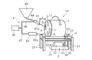
以下に、本願に係る摩耗試験装置を図面に基づいて説明する。図1は、第1実施形態における摩耗試験装置を示す。試験装置1Aは、ゴム材料の試験片を取り付ける回転体である回転ドラム1と、前記回転ドラム1を載置する架台2と、前記回転ドラム1を回転駆動する駆動装置3と、試験片に向かって摩耗材である粉状物と摩耗された試験片の表面に向かってエアーを噴射する噴射装置4とからなる。
Below, the abrasion test apparatus which concerns on this application is demonstrated based on drawing. FIG. 1 shows a wear test apparatus in the first embodiment. The
前記回転ドラム1は、中空の円筒体であり、一方の側面にゴム材料である試験片を取り付ける水平な面を有する取付板11が設けられている。試験片取付板11には、同時に異種又は同種の複数の試験片が取り付けられるように構成されており、回転ドラム1と一体に回転する。試験片取付板11に複数の試験片を同時に取り付けられるようにすることによって、異種又は同種の試験片の同一環境下での摩耗試験が可能となる。
The rotating
前記架台2は、4本の支柱21の上端部に回転ドラム1を載置する2本の回転可能なローラー22が平行に配設されており、いずれか一方のローラー22にプーリー23が取り付けられている。プーリー23が回転することによってプーリー23が取り付けられているローラー22も一体に回転し、ローラー22が回転することによって載置した回転ドラム1も回転する。
In the
従って、プーリー23が取り付けられたローラー22とプーリー23が取り付けられていないローラー22とは回転ドラム1を介して同一方向に回転することになる。2本の平行なローラー22の間隔は、回転ドラム1を安定した状態で載置できればよく、回転ドラム1の大きさによって決定すればよい。
Therefore, the
上記駆動装置3は、支持台31の上に設置されたモーター32を有し、前記モーター32の回転軸33に固定されたプーリー34にベルト35が巻回されるように構成されている。ベルト35は前記プーリー34とローラー22のプーリー23との間に巻回されている。従って、モーター32が作動するとプーリー34が回転し、ベルト35を介してプーリー23とともにローラー22が回転し、同時に回転ドラム1も回転する。
The
次に、噴射装置4について説明する。噴射装置4は、粉状物を噴射する噴射ガン41とエアーを噴射するエアーガン42を備えている。前記噴射ガン41は、先端に噴射口41aを有するノズルを有し、粉状物を貯留するタンク43と供給管44を介して連結されており、さらに、圧縮エアー供給装置であるコンプレッサー45と分岐されたエアー供給管46を介して連結されている。
Next, the
前記噴射ガン41内には、エアー供給管46の先端のノズルが開口しており、コンプレッサー45からの圧縮エアーを吐出するようになっている。噴射ガン41内には、タンク43から粒状物が供給され、供給管44内から供給された粉状物はノズルから突出され、圧縮エアーによって噴射口41aから試験片に向かって噴射される。
A nozzle at the tip of an
前記噴射ガン41の噴射口41aは、図示しない駆動機構によって上下左右方向に自由に向きを変えることができるとともに、噴射口41aと試験片との距離Lと試験片の表面に対する噴射口の角度αも任意に変更できるように配設されている。例えば、噴射口41aと試験片との距離Lを約130mm、噴射口の試験片表面に対する角度αを約60度とすることができる。
The
また、タンク43は、粉状物を所定量ずつ噴射ガン41に供給可能であり、試験片に噴射された粉状物は、図示しない装置によって回収されるように構成することができる。また、回収された粉状物は、別途設置された容器に貯留するようにしてもよいし、再びタンク43に戻るように構成してもよい。
Moreover, the
また、前記エアーガン42は、先端に噴射口42aを有するノズルが設けられており、圧縮エアー供給装置であるコンプレッサー45と分岐された供給管47を介して連結されている。前記エアーガン42の噴射口42aは、図示しない駆動機構によって上下左右方向に自由に向きを変えることができるとともに、試験片との距離も任意に変更できるように配設されている。
The
コンプレッサー45から供給された圧縮エアーはエアーガン42によって粉状物が噴射された試験片の表面に吹き付けられ、試験片上の粉状物や摩耗屑を除去する。エアーガン42による試験片への圧縮エアーの吹き付けは、粉状物が噴射された直後であっても、噴射される直前の試験片であってもよい。コンプレッサー45は、周知の構成からなり、ノズルに例えば、5.3MPaのエアー圧を供給できるようになっている。
The compressed air supplied from the
上記試験装置1Aにおいて、取付板11を設けてなる回転ドラム1をローラー22上に載置し、前記ローラー22に載置した回転ドラム1を駆動装置3によってローラー22を介して回転させることとしたが、回転ドラム1を回転させる機構は前記実施形態に限定されるものではない。例えば、回転ドラム1に直接回転軸を設け、前記回転軸にプーリーを取り付けて前記プーリーを駆動装置3のプーリーとの間に巻回したベルトによって回転ドラム1を直接回転させる構成としてもよい。
In the
また、上記実施形態では、試験片取付板11を回転ドラム1の側面に垂直に配設したが、回転ドラム1を垂直に立てて水平方向に回転するように構成し、前記試験片取付板11を水平に回転する回転ドラム1の上面に配設してもよい。
In the above-described embodiment, the test piece mounting plate 11 is disposed perpendicular to the side surface of the
上記構成の試験装置1Aによって、ゴム材料の摩耗試験を行う場合は、まず、試験片A〜Dの重量を測定した後、試験片取付板11の所定の位置に取り付ける。次に、噴射ガン41の噴射口41aの試験片との距離L(例えば、130mm)及び噴射口41aの試験片の表面との角度α(例えば、60度)を設定する。次いで、駆動装置3を作動させてベルト35、ローラー22を介して回転ドラム1を回転させる。回転ドラム1を回転させた後、噴射ガン41から試験片取付板11に取り付けた試験片A〜Dに向かって粉状物を噴射する。
When a wear test of a rubber material is performed by the
続いて、粉状物が噴射された試験片A〜Dに向かってエアーガン42から所定圧の圧縮エアーを吹き付ける。このときのエア圧は所定の値に設定することができ、例えば、エア圧を5.3MPaとすることができる。圧縮エアーの吹き付けによって、試験片上に付着した粉状物や摩耗屑を除去することができる。
Subsequently, compressed air with a predetermined pressure is blown from the
また、試験片A〜Dは回転しているために、それぞれの試験片は常時連続して粉状物が噴射されているのではなく、粉状物の噴射から一旦離れることになるので、試験片の表面が持つ熱を放熱することができる。さらに、この発明では、粉状物が噴射された試験片A〜Dに向かって圧縮エアーが吹き付けられるので、試験片表面の粉状物や摩耗屑を除去するだけではなく試験片A〜Dの表面温度を低下させることになる。 Moreover, since the test pieces A to D are rotating, each test piece is not always continuously sprayed with powdery substances, but is once separated from the injection of powdery substances. The heat of the surface of the piece can be dissipated. Furthermore, in this invention, since compressed air is sprayed toward the test pieces A to D on which the powdery material is jetted, not only the powdery materials and wear debris on the surface of the test piece but also the test pieces A to D are removed. The surface temperature will be lowered.
所定時間粉状物の噴射と圧縮エアーの吹き付けを繰り返した後に、取付板11から試験片A〜Dを取り外して各試験片の重量を測定する。続いて、粉状物の噴射によって減少した試験片A〜Dの重量変化を算出し、各試験片の耐摩耗性を相対的に評価する。 After repeating spraying of powdery substances and blowing of compressed air for a predetermined time, the test pieces A to D are removed from the mounting plate 11 and the weight of each test piece is measured. Subsequently, the weight change of the test pieces A to D decreased by the injection of the powdery material is calculated, and the wear resistance of each test piece is relatively evaluated.
上述の通り、この実施形態のゴム材料の摩耗試験方法によれば、粉状物の複数回の噴射によって試験片A〜Dの表面には大きな衝撃が加わり、この衝撃によって試験片A〜Dの表面が摩耗する。そして、粉状物の噴射は、圧縮エアーの吹き付けによって粉状物等を取り除いた新たな表面に対して行われるので、実際に使用されている現象に近いシミュレートによる評価をすることができる。 As described above, according to the rubber material wear test method of this embodiment, a large impact is applied to the surfaces of the test pieces A to D by a plurality of injections of the powder, and the impact of the test pieces A to D is caused by this impact. The surface is worn. And since injection of a powdery material is performed with respect to the new surface which removed the powdery material etc. by spraying of compressed air, evaluation by simulation close | similar to the phenomenon actually used can be performed.
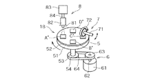
次に、この発明の第2実施形態を図2に基づいて説明する。図2に示す試験装置1Bは、移動している試験片に研磨材を一定の力で押し付ける縦型の摩耗試験装置である。試験装置1Bは、試験片を取り付ける回転体であるターンテーブル5、ターンテーブル5を回転させる駆動装置6、ターンテーブル5に取り付けられた試験片を摩耗させる摩耗輪7及び試験片にエアーを吹き付けるエアー噴射装置8によって構成されている。
Next, a second embodiment of the present invention will be described with reference to FIG. The
前記ターンテーブル5は、ターンテーブル51の表面にゴム材料である試験片を取り付ける取付板52が一体に設けられている。前記取付板52は、水平な面を有し同時に異種又は同種の複数の試験片が取り付けられるように構成されている。試験片取付板52が複数の試験片を同時に取り付けられるようにすることによって、異種又は同種の試験片の同一環境下での摩耗試験が可能となる。
The
前記ターンテーブル51は回転軸53によって支持されており、回転軸53には、ベルトを巻回するプーリー54が設けられている。尚、前記回転軸53が図示しない軸受によって支持されていることは当然である。
The
駆動装置6は、図示しない所定の台上に設置されたモーター61の回転軸62にプーリー63を固定し、前記プーリー63とプーリー54との間にベルト64を巻回してなる。従って、モーター61が作動するとプーリー63が回転し、ベルト64を介してプーリー54とともにターンテーブル51が回転する。尚、モーター61の回転軸62に減速ギヤーボックス等を配することなどの公知の構成については説明を省略する。
The driving
上記摩耗輪7は、回転軸71と摩耗材を貼り付けるローラー72を有しており、前記回転軸71は図示しない駆動装置によって回転駆動される。ローラー72は、取付板52に取り付けられた試験片に一定の力で押し付けられ、回転軸71に一定の角度を与えて試験片を摩耗させる。従って、ローラー72は、試験片への押圧力、角度あるいは正逆回転等を任意に変更できるように構成されている。
The
この第2実施形態では、摩耗輪7のローラー72と試験片と独立してそれぞれ回転させるからスリップ率、回転速度、押圧力等を任意に選ぶことによって、広範囲でしかも過酷な条件で試験することが可能となる。
In this second embodiment, the
次に、上記エアー噴射装置8は、先端に噴射口81を有するノズルを設けたエアーガン82と圧縮エアー供給装置であるコンプレッサー83を備えており、前記エアーガン82とコンプレッサー83とは供給管84を介して連結されている。前記エアーガン82の噴射口81は、図示しない駆動機構によって前後左右方向に自由に向きを変えることができるとともに、試験片との距離も任意に変更できるように配設されている。
Next, the air injection device 8 includes an
上記構成の試験装置1Bによって、ゴム材料の摩耗試験を行う場合は、まず、試験片の重量を測定した後、試験片取付板52の所定の位置に取り付ける。次に、摩耗輪7に摩耗材を巻き付けて摩耗輪7のローラー72の押圧力、角度、回転速度等を設定し、さらにエアー噴射装置8の噴射口81の試験片からの距離、試験片の表面に対する角度、エアー圧等を設定する。次いで、駆動装置6を作動させてベルト64を介してターンテーブル51とともに取付板52に取り付けた試験片A´〜D´を回転させる。
When performing the abrasion test of the rubber material by the
次いで、摩耗輪7を作動させてローラー72を回転移動している試験片に当接させる。続いて、ローラー72により摩耗された試験片に向かってエアーガン82から所定圧の圧縮エアーを吹き付ける。圧縮エアーの吹き付けによって、試験片A´〜D´上に付着した摩耗屑を除去することができる。
Next, the
この実施形態においても、試験片は回転移動しているために、それぞれの試験片は常時連続してローラー72による摩耗が行われているのではないから、試験片の表面が持つ熱を放熱することができる。さらに、エアーガン82から摩耗された試験片に向かって圧縮エアーが吹き付けられるので、試験片表面の摩耗屑を除去するだけではなく試験片の表面温度を低下させる。その他、実施形態1と同様の作用効果を奏することができる。
Also in this embodiment, since the test pieces are rotating and moving, each test piece is not continuously worn by the
以下に、ウレタンゴムシートの摩耗試験の比較例と実施例について説明する。
<比較例>
試験機には、回転ドラムに巻き付けた研磨紙上に試験片を一定荷重で押し付けて摩耗させる。NBS摩耗試験機として、出願人が製作した摩耗試験機を用いた。前記NBS摩耗試験機により、試験片の厚みが2.54mm(0.1インチ)当たりの摩耗抵抗をドラムの回転数より測定した。試験機への掛け数は3個、試験片の大きさは、25mm×25mm×厚さ6.35mmである。ドラムの回転数は45±5rpm、錘は、2.265gf用を3個用いた。試験結果は表1に示す通りである。
Below, the comparative example and Example of an abrasion test of a urethane rubber sheet are demonstrated.
<Comparative example>
In the testing machine, a test piece is pressed against the abrasive paper wound around a rotating drum with a constant load to be worn. A wear tester manufactured by the applicant was used as the NBS wear tester. With the NBS abrasion tester, the abrasion resistance per test piece thickness of 2.54 mm (0.1 inch) was measured from the number of revolutions of the drum. The multiplying number on the testing machine is 3, and the size of the test piece is 25 mm × 25 mm × thickness 6.35 mm. The number of revolutions of the drum was 45 ± 5 rpm, and three weights for 2.265 gf were used. The test results are as shown in Table 1.
<実施例1>
試験機には、図1に示す回転ドラム式摩耗試験機を用いた。試験片の大きさは、幅25.4mm×長さ110mm×厚さ1mmの短冊状のものを5個用い、両面テープで取付板に貼り付けた。試験片と噴射ガン41の噴射口41aとの距離Lを120mm、試験片表面との噴射角度を60度とし、エアー圧を5.3MPaに設定し、回転ドラム1の回転数は10rpmで行った。ブラストする粉状物には、ニッチュースチールグリット(商品名)(品番:G140H,株式会社ニッチュー製)を用いた。試験時間は4時間であった。
<Example 1>
The rotating drum type wear tester shown in FIG. 1 was used as the tester. The test specimens were 5 strips each having a width of 25.4 mm, a length of 110 mm, and a thickness of 1 mm, and affixed to the mounting plate with double-sided tape. The distance L between the test piece and the
<実施例2>
試験機、試験片の大きさ、貼付方法、試験片と噴射ガン41の噴射口41aとの距離L、試験片表面との噴射角度、エアー圧、回転ドラムの回転数、粉状物の種類等は、実施例1と同じである。試験時間のみを8時間とした。試験結果を表1に示す。
<Example 2>
Test machine, size of test piece, attaching method, distance L between test piece and
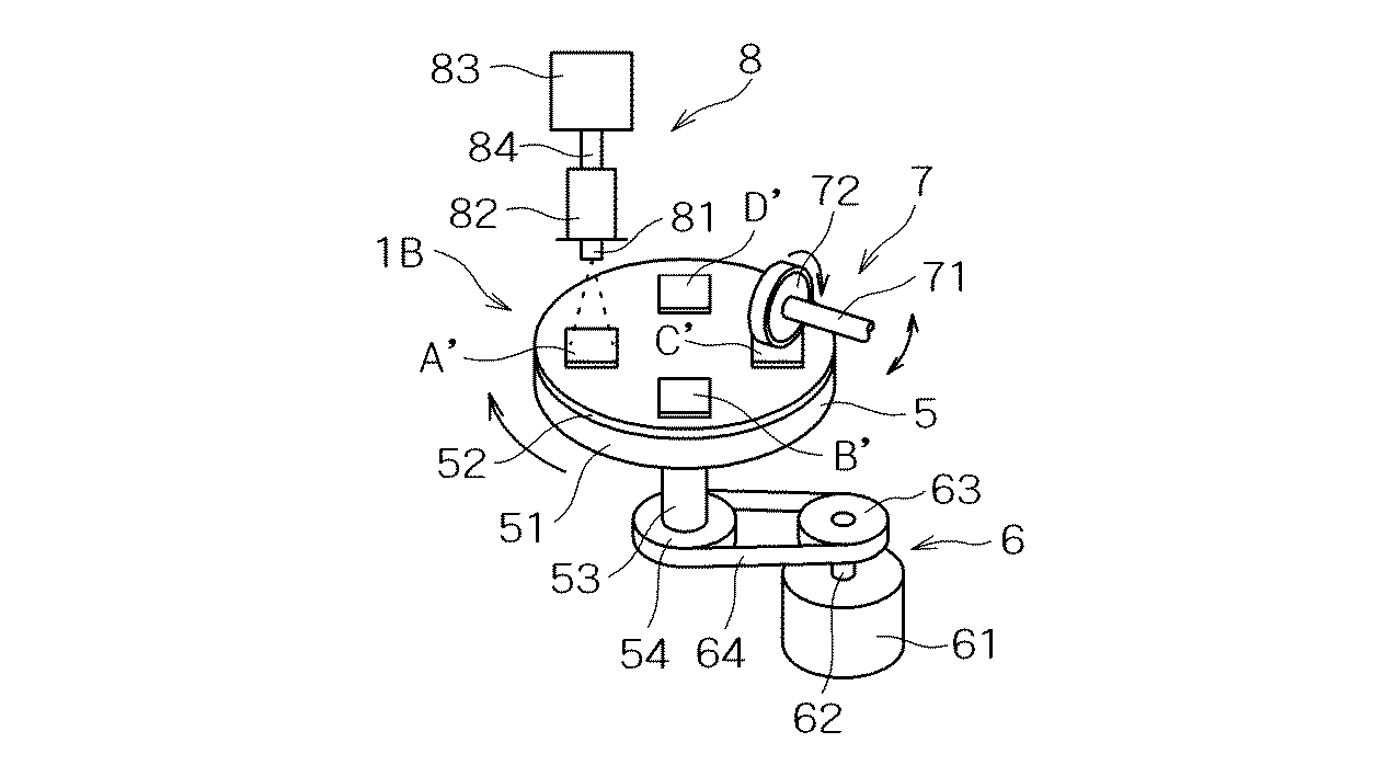
表1から明らかなように、多数のサンプルを同時に試験することができ、しかも比較例に比して同一試験環境においてバラツキのない相対評価を行うことができる。 As is apparent from Table 1, a large number of samples can be tested simultaneously, and relative evaluation without variation can be performed in the same test environment as compared with the comparative example.
1A、1B:試験装置
1:回転ドラム
2:架台
3:駆動装置
4:噴射装置
5:ターンテーブル
6:駆動装置
7:摩耗輪
8:噴射装置
11:試験片取付板
21:支柱
22:ローラー
23:プーリー
31:台
32:モーター
33:回転軸
34:プーリー
35:ベルト
41:噴射ガン
41a:噴射口
42:エアーガン
43:タンク
44:供給管
45:コンプレッサー
46:エアー供給管
51:ターンテーブル
52:試験片取付板
61:モーター
62:回転軸
63:プーリー
64:ベルト
71:回転軸
72:ローラー
81:噴射口
82:エアーガン
83:コンプレッサー
84:供給管
1A, 1B: Test device 1: Rotating drum 2: Mounting base 3: Drive device 4: Injection device 5: Turntable
6: Drive device 7: Wear wheel 8: Injection device 11: Test piece mounting plate 21: Support 22: Roller 23: Pulley 31: Stand 32: Motor 33: Rotating shaft 34: Pulley 35: Belt 41:
Claims (6)
Priority Applications (1)
| Application Number | Priority Date | Filing Date | Title |
|---|---|---|---|
| JP2011067499A JP2012202811A (en) | 2011-03-25 | 2011-03-25 | Abrasion testing method of rubber material or the like and abrasion testing device used therefor |
Applications Claiming Priority (1)
| Application Number | Priority Date | Filing Date | Title |
|---|---|---|---|
| JP2011067499A JP2012202811A (en) | 2011-03-25 | 2011-03-25 | Abrasion testing method of rubber material or the like and abrasion testing device used therefor |
Publications (1)
| Publication Number | Publication Date |
|---|---|
| JP2012202811A true JP2012202811A (en) | 2012-10-22 |
Family
ID=47183983
Family Applications (1)
| Application Number | Title | Priority Date | Filing Date |
|---|---|---|---|
| JP2011067499A Withdrawn JP2012202811A (en) | 2011-03-25 | 2011-03-25 | Abrasion testing method of rubber material or the like and abrasion testing device used therefor |
Country Status (1)
| Country | Link |
|---|---|
| JP (1) | JP2012202811A (en) |
Cited By (9)
| Publication number | Priority date | Publication date | Assignee | Title |
|---|---|---|---|---|
| CN103529228A (en) * | 2013-10-17 | 2014-01-22 | 王储连 | Full-automatic inspection equipment of non-metal products |
| JP5991404B1 (en) * | 2015-04-30 | 2016-09-14 | 横浜ゴム株式会社 | Scratch wear test apparatus and method |
| CN108318362A (en) * | 2018-02-05 | 2018-07-24 | 西华大学 | A kind of solid granulates Performance Measurement System under rolling state |
| CN109975148A (en) * | 2019-01-15 | 2019-07-05 | 中信戴卡股份有限公司 | A kind of automatic sand erosion device |
| KR20200053153A (en) * | 2018-11-08 | 2020-05-18 | 주식회사 에스에스케이 | Wear Test Apparatus |
| JP2020094832A (en) * | 2018-12-10 | 2020-06-18 | 株式会社ディスコ | Test equipment |
| CN111982733A (en) * | 2020-09-04 | 2020-11-24 | 中国核动力研究设计院 | A test device for erosion corrosion test of lead-bismuth alloy melt |
| CN112763308A (en) * | 2020-12-29 | 2021-05-07 | 哈尔滨工程大学 | Multi-degree-of-freedom erosion auxiliary system capable of continuously adjusting and monitoring in real time |
| KR20230030970A (en) * | 2021-08-26 | 2023-03-07 | 현대제철 주식회사 | Rolling condition simulation type evaluation apparatus for casting material |
-
2011
- 2011-03-25 JP JP2011067499A patent/JP2012202811A/en not_active Withdrawn
Cited By (19)
| Publication number | Priority date | Publication date | Assignee | Title |
|---|---|---|---|---|
| CN103529228A (en) * | 2013-10-17 | 2014-01-22 | 王储连 | Full-automatic inspection equipment of non-metal products |
| US11231353B2 (en) | 2015-04-30 | 2022-01-25 | The Yokohama Rubber Co., Ltd. | Scratch abrasion tester and testing method |
| JP5991404B1 (en) * | 2015-04-30 | 2016-09-14 | 横浜ゴム株式会社 | Scratch wear test apparatus and method |
| AU2016253804B2 (en) * | 2015-04-30 | 2018-09-13 | The Yokohama Rubber Co., Ltd. | Abrasive wear test device and method |
| WO2016174940A1 (en) * | 2015-04-30 | 2016-11-03 | 横浜ゴム株式会社 | Abrasive wear test device and method |
| US10732084B2 (en) | 2015-04-30 | 2020-08-04 | The Yokohama Rubber Co., Ltd. | Scratch abrasion tester and testing method |
| CN108318362A (en) * | 2018-02-05 | 2018-07-24 | 西华大学 | A kind of solid granulates Performance Measurement System under rolling state |
| CN108318362B (en) * | 2018-02-05 | 2023-07-25 | 西华大学 | A system for measuring the properties of solid particles in rolling state |
| KR20200053153A (en) * | 2018-11-08 | 2020-05-18 | 주식회사 에스에스케이 | Wear Test Apparatus |
| KR102137322B1 (en) | 2018-11-08 | 2020-07-23 | 주식회사 에스에스케이 | Wear Test Apparatus |
| JP2020094832A (en) * | 2018-12-10 | 2020-06-18 | 株式会社ディスコ | Test equipment |
| JP7134569B2 (en) | 2018-12-10 | 2022-09-12 | 株式会社ディスコ | test equipment |
| CN109975148A (en) * | 2019-01-15 | 2019-07-05 | 中信戴卡股份有限公司 | A kind of automatic sand erosion device |
| CN109975148B (en) * | 2019-01-15 | 2024-01-26 | 中信戴卡股份有限公司 | Automatic sand grain wearing and tearing device |
| CN111982733A (en) * | 2020-09-04 | 2020-11-24 | 中国核动力研究设计院 | A test device for erosion corrosion test of lead-bismuth alloy melt |
| CN112763308A (en) * | 2020-12-29 | 2021-05-07 | 哈尔滨工程大学 | Multi-degree-of-freedom erosion auxiliary system capable of continuously adjusting and monitoring in real time |
| CN112763308B (en) * | 2020-12-29 | 2022-11-25 | 哈尔滨工程大学 | A continuously adjustable and real-time monitoring multi-degree-of-freedom erosion assistance system |
| KR102533587B1 (en) | 2021-08-26 | 2023-05-18 | 현대제철 주식회사 | Rolling condition simulation type evaluation apparatus for casting material |
| KR20230030970A (en) * | 2021-08-26 | 2023-03-07 | 현대제철 주식회사 | Rolling condition simulation type evaluation apparatus for casting material |
Similar Documents
| Publication | Publication Date | Title |
|---|---|---|
| JP2012202811A (en) | Abrasion testing method of rubber material or the like and abrasion testing device used therefor | |
| CN106574885B (en) | Impact test device and method | |
| JP7018938B2 (en) | A device for measuring rubber wear | |
| US7182671B1 (en) | Blasting apparatus and blasting method | |
| EP3290903B1 (en) | Abrasive wear test device and method | |
| JP6531363B2 (en) | Abrasion test apparatus and method | |
| US20190003946A1 (en) | Testing and/or Inspection Device | |
| KR20080113508A (en) | Abrasion test device for plastic surface for vehicle interior | |
| ATE497845T1 (en) | METHOD FOR REPAIRING A GAS TURBINE ENGINE COMPONENT | |
| CN101603917A (en) | Method and equipment for testing adhesion of slider coating | |
| TW201107745A (en) | Fast abrasion test for granules | |
| JP2004020319A (en) | Conveyor belt wear test equipment | |
| CN108760551A (en) | The device and method of the secondary assessment material abrasion behavior of Wheel-type friction | |
| JP2005283416A (en) | Abrasion testing apparatus and its method | |
| CN104215536A (en) | Cladding layer abrasion-resisting performance testing device | |
| GB2516107A (en) | Surface Cleaning Apparatus | |
| JP3706637B2 (en) | Viscoelastic body wear test equipment | |
| JP5297844B2 (en) | Disc-shaped rubber test piece for rubber testing machine and rubber testing machine using the same | |
| US743911A (en) | Machine for grinding or polishing sheet metal. | |
| JP2013170929A (en) | Tire wear testing apparatus | |
| KR101446079B1 (en) | The air nozzle wiping performance test device | |
| JP2595040B2 (en) | Friction and wear testing machine | |
| JP6503694B2 (en) | Impact test apparatus and method | |
| US3059463A (en) | Standard test article | |
| KR101288963B1 (en) | Sand blast abrasion test apparatus |
Legal Events
| Date | Code | Title | Description |
|---|---|---|---|
| A300 | Withdrawal of application because of no request for examination |
Free format text: JAPANESE INTERMEDIATE CODE: A300 Effective date: 20140603 |