JP2012203111A - Stereoscopic image display device - Google Patents

Stereoscopic image display device Download PDF

Info

Publication number
JP2012203111A
JP2012203111A JP2011066159A JP2011066159A JP2012203111A JP 2012203111 A JP2012203111 A JP 2012203111A JP 2011066159 A JP2011066159 A JP 2011066159A JP 2011066159 A JP2011066159 A JP 2011066159A JP 2012203111 A JP2012203111 A JP 2012203111A
Authority
JP
Japan
Prior art keywords
polarized light
image
liquid crystal
image forming
stereoscopic image
Prior art date
Legal status (The legal status is an assumption and is not a legal conclusion. Google has not performed a legal analysis and makes no representation as to the accuracy of the status listed.)
Pending
Application number
JP2011066159A
Other languages
Japanese (ja)
Inventor
Kenji Matsuhiro
憲治 松廣
Michiyuki Kono
通之 河野
Kazuhiro Sugiura
和浩 杉浦
Current Assignee (The listed assignees may be inaccurate. Google has not performed a legal analysis and makes no representation or warranty as to the accuracy of the list.)
Arisawa Mfg Co Ltd
Original Assignee
Arisawa Mfg Co Ltd
Priority date (The priority date is an assumption and is not a legal conclusion. Google has not performed a legal analysis and makes no representation as to the accuracy of the date listed.)
Filing date
Publication date
Application filed by Arisawa Mfg Co Ltd filed Critical Arisawa Mfg Co Ltd
Priority to JP2011066159A priority Critical patent/JP2012203111A/en
Publication of JP2012203111A publication Critical patent/JP2012203111A/en
Pending legal-status Critical Current

Links

Images

Landscapes

  • Stereoscopic And Panoramic Photography (AREA)
  • Testing, Inspecting, Measuring Of Stereoscopic Televisions And Televisions (AREA)

Abstract

【課題】専用のメガネを用いること無く、左右同時視が可能で画面解像度の低下とクロストークが低減された立体画像表示装置を提供する。
【解決手段】立体画像表示装置1は、バックライト2と、複数の水平ライン23からなる第一画像形成領域21および第二画像形成領域22を有する液晶ディスプレイ5との間に集光レンズであるフレネルレンズ3と第一偏光領域31および第二偏光領域32を有する光学手段の位相差板4とを有する。フレーム画像は、第一画像形成領域21に右目用画像を、第二画像形成領域22に左目用画像を表示し、フレーム切り替え毎に画像形成領域を交互に入れ替えるかまたは上書きされる。バックライト2は、第一画像形成領域21と第二画像形成領域22での右目用画像または左目用画像の表示に合わせ、中央を境にした左右から互いに偏光方向の異なる直線偏光または円偏光を放射する。
【選択図】図1
The present invention provides a stereoscopic image display device capable of simultaneous left-right viewing without using dedicated glasses, with reduced screen resolution and reduced crosstalk.
A stereoscopic image display device 1 is a condensing lens between a backlight 2 and a liquid crystal display 5 having a first image forming region 21 and a second image forming region 22 each including a plurality of horizontal lines 23. It has a Fresnel lens 3 and a retardation plate 4 of optical means having a first polarizing region 31 and a second polarizing region 32. The frame image displays the right-eye image in the first image forming area 21 and the left-eye image in the second image forming area 22, and the image forming areas are alternately switched or overwritten every frame switching. The backlight 2 applies linearly polarized light or circularly polarized light having different polarization directions from the left and right with the center as the boundary in accordance with the display of the right-eye image or the left-eye image in the first image forming area 21 and the second image forming area 22. Radiate.
[Selection] Figure 1

Description

本発明は、立体画像表示装置に関する。   The present invention relates to a stereoscopic image display device.

近年、平面表示パネルを使用した薄型テレビの開発が盛んに行われ、例えば、液晶パネルを使用した液晶テレビの開発が行われている。そして、薄型テレビを高機能化する一つの取り組みとして、立体画像を表示する立体画像表示装置の開発が進められている。   In recent years, thin televisions using a flat display panel have been actively developed. For example, liquid crystal televisions using a liquid crystal panel have been developed. Then, as one approach for improving the functionality of a thin-screen television, development of a stereoscopic image display device that displays a stereoscopic image is being promoted.

液晶パネルからなる液晶ディスプレイを用い、立体画像表示装置を構成する技術については、多数の方式が提案されている。それらは、特許文献1に開示されるような、立体映像を観察する際に観察者が専用のメガネを必要とする方式と、特許文献2に開示されるような、メガネを必要としない方式に分類することができる。   A number of methods have been proposed for a technique for configuring a stereoscopic image display device using a liquid crystal display composed of a liquid crystal panel. They are a method in which an observer needs special glasses when observing a stereoscopic image as disclosed in Patent Document 1, and a method in which glasses are not required as disclosed in Patent Document 2. Can be classified.

専用のメガネを使用する立体画像の表示方式としては、シャッターメガネ方式が知られている。この方式は、解像度の低下が無く、画像表示装置における表示の視野角も広くなるという利点を有する。しかしながら、この方式は、専用のメガネを使用する煩雑さに加え、表示画像がちらつくフリッカーの発生、表示画面における輝度の低下、および左右の眼に映る画像の時間差により観察者は自然な画像を得られないという問題点などを有している。   As a stereoscopic image display method using dedicated glasses, the shutter glasses method is known. This method has the advantage that the resolution is not lowered and the viewing angle of the display in the image display device is widened. However, in this method, in addition to the complexity of using dedicated glasses, the observer obtains a natural image due to the occurrence of flicker that causes the display image to flicker, the decrease in brightness on the display screen, and the time difference between the images displayed on the left and right eyes. There is a problem that it is not possible.

また、特許文献1には、新規な光学手段として、入射した光の偏光軸を互いに直交させるよう二つの異なる偏光領域を有する位相差板を用いる立体画像表示装置が開示されている。この立体画像表示装置は、右目用の画像と左目用の画像をそれぞれ異なる領域に表示させる液晶ディスプレイと、その左右画像表示領域に対応するよう配置された上記の位相差板とを備え、観察者に視差画像を投影させて立体画像が得られるように構成されている。   Patent Document 1 discloses a stereoscopic image display device using a phase difference plate having two different polarization regions so that the polarization axes of incident light are orthogonal to each other as a novel optical means. This stereoscopic image display device includes a liquid crystal display that displays a right-eye image and a left-eye image in different areas, and the above-described retardation plate that is arranged to correspond to the left and right image display areas. 3D images can be obtained by projecting parallax images onto the screen.

この特許文献1に記載の立体画像表示装置においては、表示画面の右目用映像信号に従う表示の位置と左目用映像信号に従う表示の位置が常に固定されている。したがって、左右映像とも垂直解像度が半減してしまうという課題を有している。また、立体表示装置の鉛直方向に対し、ある視野角の位置から観察すると、液晶ディスプレイ上の右目用画像の一部が左目用の1/2波長板を通過して観察者の左目に届いてしまう。すなわち、観察する位置によりクロストークを生じるという新たな課題を有している。   In the stereoscopic image display device described in Patent Document 1, the display position according to the right-eye video signal and the display position according to the left-eye video signal on the display screen are always fixed. Therefore, both the left and right images have a problem that the vertical resolution is halved. Further, when observing from the position of a certain viewing angle with respect to the vertical direction of the stereoscopic display device, a part of the image for the right eye on the liquid crystal display reaches the left eye of the observer through the half-wave plate for the left eye. End up. In other words, there is a new problem that crosstalk occurs depending on the observation position.

特開2006−284873号公報JP 2006-284873 A 特開平10−63199号公報JP-A-10-63199

近年盛んに開発が進められているのが、立体映像を観察する際に観察者が専用のメガネを必要としない方式である。
専用のメガネを必要としない方式としては、例えば、パララックスバリア方式、レンチキュラレンズ方式、スイッチバックライト式などが知られている。しかし、パララックスバリア方式やレンチキュラレンズ方式においては、水平解像度が低下するなど、画像表示の解像度が低下してしまうという問題点を有する。スイッチバックライト式においては、画像のちらつきであるフリッカーが発生するという不具合を有している。
In recent years, a method that does not require dedicated glasses when observing a stereoscopic image has been actively developed.
As methods that do not require special glasses, for example, a parallax barrier method, a lenticular lens method, a switch backlight method, and the like are known. However, the parallax barrier method and the lenticular lens method have a problem that the resolution of image display is lowered, for example, the horizontal resolution is lowered. The switch backlight type has a problem that flicker, which is image flickering, occurs.

また、別の構成の光学手段を利用し、立体画像を得る立体画像表示装置が提案されている。例えば、特許文献2には、光学手段である偏光フィルタやフレネルレンズを用い、専用のメガネを必要としない立体画像表示装置が開示されている。   In addition, a stereoscopic image display apparatus that obtains a stereoscopic image using an optical unit having another configuration has been proposed. For example, Patent Document 2 discloses a stereoscopic image display device that uses a polarizing filter or a Fresnel lens as optical means and does not require special glasses.

この特許文献2に記載の立体画像表示装置においては、液晶ディスプレイを挟んで観察者の反対側に配置された光源の前面左右に、偏光方向が直交する右目用偏光フィルタ部と左目用偏光フィルタ部とが配置される。各フィルタ部を通過した互いに直交する偏光光はフレネルレンズにより略平行光とされ、背面側から液晶ディスプレイに向けて照射される。液晶ディスプレイでは、両面に偏光フィルタが配設されている。偏光フィルタのそれぞれにおいては、液晶ディスプレイの1水平ラインに対応するよう、水平ライン毎に、互いに直交する直線偏光フィルタライン部が交互に配置されている。このとき、光源側と観察者側の対向する直線偏光フィルタライン部についても互いに直交する偏光方向となるようにされている。そして、液晶ディスプレイの液晶パネルにおいて、2枚の偏光フィルタの透光ラインに合わせて1水平ライン毎に右眼用と左眼用の映像情報を交互に表示するよう構成する。   In the stereoscopic image display device described in Patent Document 2, right-eye polarization filter sections and left-eye polarization filter sections whose polarization directions are orthogonal to each other on the front and right sides of a light source disposed on the opposite side of the observer across the liquid crystal display. And are arranged. The mutually orthogonally polarized light beams that have passed through the filter parts are made substantially parallel light by the Fresnel lens, and are irradiated toward the liquid crystal display from the back side. In the liquid crystal display, polarizing filters are disposed on both sides. In each of the polarizing filters, linear polarizing filter line portions orthogonal to each other are alternately arranged for each horizontal line so as to correspond to one horizontal line of the liquid crystal display. At this time, the linearly polarizing filter line portions facing each other on the light source side and the viewer side are set to have polarization directions orthogonal to each other. Then, the liquid crystal panel of the liquid crystal display is configured to alternately display the video information for the right eye and the left eye for each horizontal line in accordance with the light transmission lines of the two polarizing filters.

すなわち、特許文献2に記載の立体画像表示装置は、表示画面の全水平ラインを奇数ラインと偶数ラインに分割し、それぞれのラインに左目用および右目用画像を表示してこれらをその新規な光学手段で観察者の左右の目に振り分けて立体画像を表示するものである。   That is, the stereoscopic image display device described in Patent Document 2 divides all horizontal lines of a display screen into odd lines and even lines, displays left-eye and right-eye images on the respective lines, and displays them as the new optical lines. The three-dimensional image is displayed by allocating to the left and right eyes of the observer.

この装置によれば、観察者は専用のメガネ無しで立体画像を観察することができる。そして、観察者の見る位置が多少左右にずれても立体画像が損なわれることは無い。さらに、パララックスバリア方式やレンチキュラレンズ方式において課題とされた水平解像度が半減してしまう現象は回避することができる。   According to this apparatus, an observer can observe a stereoscopic image without dedicated glasses. And even if the position seen by the observer is slightly shifted left and right, the stereoscopic image is not damaged. Furthermore, the phenomenon that the horizontal resolution, which is a problem in the parallax barrier method and the lenticular lens method, is halved can be avoided.

しかしながら、特許文献2に記載の偏光フィルタ等を用いた立体画像表示装置においては、表示画面の右目用映像信号に従う表示の位置と左目用映像信号に従う表示の位置が常に固定されている。したがって、左右映像とも垂直解像度が半減してしまうという課題を有している。   However, in the stereoscopic image display device using the polarization filter described in Patent Document 2, the display position according to the right-eye video signal and the display position according to the left-eye video signal on the display screen are always fixed. Therefore, both the left and right images have a problem that the vertical resolution is halved.

したがって、専用のメガネを必要としない方式において、画面での高い輝度を維持しながらフリッカーやクロストークを低減し、さらに解像度の低下を防止するためには、従来の立体画像表示装置では不充分であり、新たな立体画像表示装置が求められている。   Therefore, in a method that does not require dedicated glasses, a conventional stereoscopic image display device is insufficient to reduce flicker and crosstalk while maintaining high brightness on the screen, and to prevent a decrease in resolution. There is a need for a new stereoscopic image display device.

本発明は、こうした点に鑑みてなされたものである。すなわち、本発明の目的は、専用のメガネを不要とし、フリッカーとクロストークが低減され、画面の解像度を低下させること無く左右画像の同時視ができる、高輝度の立体画像表示装置を提供することにある。   The present invention has been made in view of these points. That is, an object of the present invention is to provide a high-intensity stereoscopic image display device that eliminates the need for dedicated glasses, reduces flicker and crosstalk, and can simultaneously view left and right images without reducing the screen resolution. It is in.

本発明の他の目的および利点は、以下の記載から明らかとなるであろう。   Other objects and advantages of the present invention will become apparent from the following description.

本発明の態様は、画素を水平方向に配列してなる水平ラインを垂直方向に複数並べて構成された液晶パネルおよびその液晶パネルを挟持する一対の偏光板を有する液晶ディスプレイと、
偏光を放射する複数の偏光光源を、左右に隣接する偏光光源の間で放射光の偏光方向が互いに異なるよう、水平方向に配列してなる偏光光源の列を備えたバックライトとを有し、
液晶ディスプレイとバックライトとの間に集光レンズと光学手段とをこの順で配置し、
観察者に立体画像を提供する立体画像表示装置であって、
バックライトは、偏光光源の列を垂直方向に複数列配置するとともに、垂直方向に隣接する偏光光源の列の間では、垂直方向に隣接する偏光光源間で放射光の偏光方向が互いに異なるように構成されており、
集光レンズは、バックライトからの光を観察者に向けて集光する光にするよう構成されたものであり、
液晶ディスプレイは、液晶パネルの連設された複数の水平ラインからなる第一画像形成領域と第二画像形成領域とを交互に配置して有し、第一画像形成領域は右目用画像および左目用画像のいずれか一方の画像を、第二画像形成領域は他方の画像をそれぞれ同時に表示するよう構成され、
第一画像形成領域と第二画像形成領域は、
(1)フレーム切り替え毎に右目用画像と左目用画像の入れ替えを行うか、
または、
(2)(1)以外の場合であって、フレームの切り替え時に右目用画像と左目用画像の入れ替えおよび直前のフレームで表示された画像の上書きのいずれか一方を行うよう構成されており、
光学手段は、第一画像形成領域と第二画像形成領域とに対応する位置と大きさで、第一偏光領域と第二偏光領域とが配置され、第一偏光領域と第二偏光領域とは、いずれか一方が1/2波長板を形成するか、両方が遅相軸が互い45度異なる1/2波長板を形成するか、または両方が遅相軸が互い90度異なる1/4波長板を形成するによう構成されたものであることを特徴とする立体画像表示装置に関する。
Aspects of the present invention include a liquid crystal panel configured by arranging a plurality of horizontal lines in which pixels are arranged in the horizontal direction in the vertical direction, and a liquid crystal display having a pair of polarizing plates sandwiching the liquid crystal panel;
A plurality of polarized light sources that emit polarized light, and a backlight having a row of polarized light sources arranged in a horizontal direction so that the polarization directions of the emitted light are different between the polarized light sources adjacent to the left and right;
A condenser lens and optical means are arranged in this order between the liquid crystal display and the backlight,
A stereoscopic image display device that provides a stereoscopic image to an observer,
In the backlight, a plurality of rows of polarized light sources are arranged in the vertical direction, and between the rows of polarized light sources adjacent in the vertical direction, the polarization direction of the emitted light is different between the polarized light sources adjacent in the vertical direction. Configured,
The condensing lens is configured to make the light from the backlight condensing toward the observer,
The liquid crystal display has a first image forming area and a second image forming area, each of which is composed of a plurality of horizontal lines connected to the liquid crystal panel, and the first image forming area is a right-eye image and a left-eye image. The second image forming area is configured to display one of the images at the same time, and the other image is displayed simultaneously.
The first image forming area and the second image forming area are
(1) Whether the image for the right eye and the image for the left eye are switched every time the frame is switched,
Or
(2) In cases other than (1), when switching frames, the right-eye image and the left-eye image are interchanged and the image displayed in the previous frame is overwritten.
The optical means has a position and a size corresponding to the first image forming area and the second image forming area, the first polarizing area and the second polarizing area are arranged, and the first polarizing area and the second polarizing area are Either one forms a half-wave plate, both form half-wave plates whose slow axes are 45 degrees different from each other, or both are quarter wavelengths whose slow axes are 90 degrees different from each other The present invention relates to a stereoscopic image display device that is configured to form a plate.

本発明の態様において、バックライトは、偏光光源の列毎に点灯制御されるよう構成されたものであることが好ましい。   In the aspect of the present invention, it is preferable that the backlight is configured so that lighting is controlled for each column of the polarized light source.

本発明の態様において、バックライトは、偏光光源毎に点灯制御されるよう構成されたものであることが好ましい。   In the aspect of the present invention, the backlight is preferably configured so that lighting is controlled for each polarized light source.

本発明の態様において、バックライトの偏光光源の列は、4つ以上の偏光光源からなることが好ましい。   In the aspect of the present invention, it is preferable that the column of the polarized light sources of the backlight includes four or more polarized light sources.

本発明の態様において、バックライトは、偏光光源の列を、上下方向に4列以上配置して構成されたものであることが好ましい。   In the aspect of the present invention, the backlight is preferably configured by arranging four or more rows of polarized light sources in the vertical direction.

本発明の態様において、バックライトは、右目用画像と左目用画像を入れ替えるタイミングに合わせて、全体の点灯状態が制御されるよう構成されたものであることが好ましい。   In the aspect of the present invention, it is preferable that the backlight is configured so that the entire lighting state is controlled in accordance with the timing at which the right-eye image and the left-eye image are switched.

本発明の態様において、バックライトの偏光光源は、LEDと偏光板とを用いて構成されたものであることが好ましい。   In the aspect of the present invention, the polarized light source of the backlight is preferably configured using an LED and a polarizing plate.

本発明の態様において、光学手段の第一偏光領域と第二偏光領域との境界の少なくとも一部には、遮光部が設けられていることが好ましい。   In the aspect of the present invention, it is preferable that a light shielding portion is provided at least at a part of the boundary between the first polarizing region and the second polarizing region of the optical means.

本発明の態様において、第一画像形成領域と第二画像形成領域とはそれぞれ、液晶パネルの垂直方向に連続して並べられた2本から60本の水平ラインからなる画像形成領域であることが好ましい。   In the aspect of the present invention, each of the first image forming area and the second image forming area is an image forming area composed of 2 to 60 horizontal lines arranged continuously in the vertical direction of the liquid crystal panel. preferable.

本発明の態様において、第一画像形成領域と第二画像形成領域とはそれぞれ、液晶パネルの垂直方向に連続して並べられた3本から30本の水平ラインからなる画像形成領域であることが好ましい。   In the aspect of the present invention, each of the first image forming area and the second image forming area is an image forming area composed of 3 to 30 horizontal lines arranged continuously in the vertical direction of the liquid crystal panel. preferable.

本発明の態様において、第一画像形成領域と第二画像形成領域とはそれぞれ、液晶パネルの垂直方向に連続して並べられた5本から15本の水平ラインからなる画像形成領域であることが好ましい。   In the aspect of the present invention, each of the first image forming area and the second image forming area is an image forming area composed of 5 to 15 horizontal lines arranged continuously in the vertical direction of the liquid crystal panel. preferable.

本発明の態様において、液晶ディスプレイにおけるフレームの切り替えは、120Hz以上の周期で行われることが好ましい。   In the aspect of the present invention, the frame switching in the liquid crystal display is preferably performed at a period of 120 Hz or more.

本発明の態様において、液晶ディスプレイにおけるフレームの切り替えは、240Hz以上の周期で行われることが好ましい。   In the aspect of the present invention, the frame switching in the liquid crystal display is preferably performed at a cycle of 240 Hz or more.

本発明によれば、専用のメガネを用いること無く、フリッカーとクロストークが低減され、画面の解像度を低下させること無く左右画像の同時視ができる広視野角の立体画像表示装置を提供することができる。   According to the present invention, it is possible to provide a stereoscopic image display device with a wide viewing angle that can reduce the flicker and crosstalk without using dedicated glasses and can simultaneously view left and right images without reducing the screen resolution. it can.

本発明の第1実施形態の立体画像表示装置の要部構成を説明する模式的な分解斜視図である。It is a typical exploded perspective view explaining the principal part composition of the stereoscopic image display device of a 1st embodiment of the present invention. 本発明の第1実施形態の立体画像表示装置の光学系を模式的に説明する平面図である。It is a top view which illustrates typically the optical system of the three-dimensional image display apparatus of 1st Embodiment of this invention. 本発明の第1実施形態の立体画像表示装置のバックライトの有する偏光板の偏光特性を説明する平面図である。It is a top view explaining the polarization characteristic of the polarizing plate which the backlight of the three-dimensional image display device of a 1st embodiment of the present invention has. 本実施の形態の立体画像表示装置を構成する液晶パネルの模式的な平面図である。It is a typical top view of the liquid crystal panel which comprises the three-dimensional image display apparatus of this Embodiment. 本発明の第2実施形態の立体画像表示装置の要部構成を説明する模式的な分解斜視図である。It is a typical disassembled perspective view explaining the principal part structure of the three-dimensional image display apparatus of 2nd Embodiment of this invention. 本発明の第3実施形態の立体画像表示装置の要部構成を説明する模式的な分解斜視図である。It is a typical exploded perspective view explaining the principal part structure of the three-dimensional image display apparatus of 3rd Embodiment of this invention. 本発明の第3実施形態の立体画像表示装置の光学系を模式的に説明する平面図である。It is a top view which illustrates typically the optical system of the three-dimensional image display apparatus of 3rd Embodiment of this invention. 液晶素子を有するバックライトの構成を模式的に説明する分解斜視図である。It is a disassembled perspective view which illustrates typically the structure of the backlight which has a liquid crystal element. (a)は、バックライトから放射される光の偏光特性の一例を模式的に示す図であり、(b)は、バックライトから放射される光の偏光特性の別の例を模式的に示す図である。(A) is a figure which shows typically an example of the polarization characteristic of the light radiated | emitted from a backlight, (b) shows typically another example of the polarization characteristic of the light radiated | emitted from a backlight. FIG. 本発明の第4実施形態の立体画像表示装置の有するバックライトを模式的に説明する平面図である。It is a top view which illustrates typically the backlight which the stereoscopic image display apparatus of 4th Embodiment of this invention has. 本発明の第4実施形態の立体画像表示装置の光学系を模式的に説明する側面図である。It is a side view which illustrates typically the optical system of the three-dimensional image display apparatus of 4th Embodiment of this invention.

<実施の形態1>
本発明の第1実施形態の立体画像表示装置1は、立体画像の観察に好適な視点(観察位置)が1つ形成されるよう構成されている。
<Embodiment 1>
The stereoscopic image display device 1 according to the first embodiment of the present invention is configured such that one viewpoint (observation position) suitable for observation of a stereoscopic image is formed.

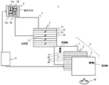
図1は、本発明の第1実施形態の立体画像表示装置1の要部構成を説明する模式的な分解斜視図である。
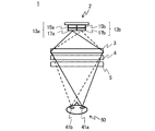
図2は、本発明の第1実施形態の立体画像表示装置1の光学系を模式的に説明する平面図である。
FIG. 1 is a schematic exploded perspective view for explaining a main configuration of the stereoscopic image display apparatus 1 according to the first embodiment of the present invention.
FIG. 2 is a plan view schematically illustrating the optical system of the stereoscopic image display apparatus 1 according to the first embodiment of the present invention.

図1および図2に示すように、立体画像表示装置1は、バックライト2と、集光レンズであるフレネルレンズ3と、光学手段である位相差板4と、液晶ディスプレイ5とをこの順で備える。そして、バックライト2と液晶ディスプレイ5の駆動をそれぞれ制御する制御装置12を備える。これらは図示されない筐体に収容される。そして、図1および図2に示すように、立体画像を観察する観察者50は液晶ディスプレイ5の前面側から画面上の立体画像を観察する。
以下、立体画像表示装置1の主要な構成について説明する。
As shown in FIGS. 1 and 2, the stereoscopic image display apparatus 1 includes a backlight 2, a Fresnel lens 3 that is a condensing lens, a phase difference plate 4 that is optical means, and a liquid crystal display 5 in this order. Prepare. And the control apparatus 12 which respectively controls the drive of the backlight 2 and the liquid crystal display 5 is provided. These are housed in a housing (not shown). As shown in FIGS. 1 and 2, the observer 50 who observes the stereoscopic image observes the stereoscopic image on the screen from the front side of the liquid crystal display 5.
Hereinafter, a main configuration of the stereoscopic image display apparatus 1 will be described.

バックライト2は、観察者50から見て立体画像表示装置1の最も奥側に配置される。
本発明の第1実施形態の立体画像表示装置1において、バックライト2は、それぞれ水平方向に伸びる、上下2つの光源の列(第1列と第2列)から構成されている。上下二つの光源の列は、それぞれ、偏光光源2つずつ(偏光光源13aと偏光光源13b、および偏光光源14aと偏光光源14b)から構成されている。
The backlight 2 is disposed on the farthest side of the stereoscopic image display device 1 when viewed from the observer 50.
In the three-dimensional image display device 1 according to the first embodiment of the present invention, the backlight 2 is composed of two upper and lower light source rows (first row and second row) extending in the horizontal direction. Each of the upper and lower light source columns is composed of two polarized light sources (a polarized light source 13a and a polarized light source 13b, and a polarized light source 14a and a polarized light source 14b).

すなわち、バックライト2を構成する上下二列の光源の列のうち、上側の第1列では、中央を境にして、2つの偏光光源13a、13bが左右に配置されている。第1列の下側にある第2列では、中央を境にして、2つの偏光光源14a、14bが左右に配置されている。
4つの偏光光源13a、13b、14a、14bは、制御装置12により、それぞれ独立に、点灯状態の制御が可能となるようにされており、上下二つの光源の列ごとに点灯状態の制御を行うことができる。
That is, of the upper and lower two rows of light source columns constituting the backlight 2, two polarized light sources 13 a and 13 b are arranged on the left and right sides with the center as a boundary. In the second row below the first row, two polarized light sources 14a and 14b are arranged on the left and right sides with the center as a boundary.
The four polarized light sources 13a, 13b, 14a, and 14b can be independently controlled by the control device 12, and the lighting state is controlled for each of the upper and lower light source columns. be able to.

偏光光源13a、13bは、ぞれぞれ、図2に示すように、白色の無偏光を放射する光源15a、15bの前面に偏光板17a、17bを配置して構成される。図2に示されない偏光光源14a、14bについても、同様に、それぞれ、白色の無偏光を放射する光源の前面に偏光板を配置して構成される。偏光板は、透過軸およびその透過軸に直交する吸収軸を有する。例えば、バックライト2の光源15aや光源15bから出射した無偏光が偏光板に入射すると、その無偏光のうち透過軸方向と平行な偏光軸の光を透過し、吸収軸方向と平行な偏光軸の光を遮断する。ここで、偏光軸の方向とは、光における電界の振動方向のことである。   As shown in FIG. 2, the polarized light sources 13a and 13b are configured by disposing polarizing plates 17a and 17b in front of the light sources 15a and 15b that emit white non-polarized light. Similarly, the polarized light sources 14a and 14b not shown in FIG. 2 are each configured by disposing a polarizing plate in front of a light source that emits white non-polarized light. The polarizing plate has a transmission axis and an absorption axis perpendicular to the transmission axis. For example, when non-polarized light emitted from the light source 15a or the light source 15b of the backlight 2 enters the polarizing plate, light having a polarization axis parallel to the transmission axis direction of the non-polarized light is transmitted and a polarization axis parallel to the absorption axis direction. Block the light. Here, the direction of the polarization axis is the vibration direction of the electric field in the light.

偏光光源13a、13b、14a、14bは、例えば、白色の無偏光を放射する点光源を用いて構成することができる。具体的には、偏光光源13a、13b、14a、14bを、LEDなどを用いて構成することができる。   The polarized light sources 13a, 13b, 14a, and 14b can be configured using, for example, a point light source that emits white non-polarized light. Specifically, the polarized light sources 13a, 13b, 14a, and 14b can be configured using LEDs or the like.

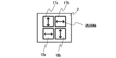
図3は、バックライト2の有する偏光板17a、17b、18a、18bの偏光特性を説明する平面図である。図3の中で、各偏光板17a、17b、18a、18b上の矢印は、偏光板17a、17b、18a、18bそれぞれの透過軸を表している。   FIG. 3 is a plan view for explaining the polarization characteristics of the polarizing plates 17a, 17b, 18a, and 18b of the backlight 2. As shown in FIG. In FIG. 3, the arrow on each polarizing plate 17a, 17b, 18a, 18b represents the transmission axis of each polarizing plate 17a, 17b, 18a, 18b.

光源の第1列を構成し、中央を境にして左右に配置される偏光光源14aと偏光光源14bとにおいて、偏光板17aと偏光板17bとは、互いに偏光方向が直交する。例えば、図1および図2に示すように、水平な地面に立つ観察者50と向き合うように立体画像表示装置1の画面を設置することができる。その場合、図3に示すように、偏光板17aにおいて、透過軸は水平方向と垂直な方向に設定され、偏光板17bにおいて、透過軸は水平方向に設定される。また、光源の第1列と第2列との関係については、2つの列の間で上下に隣接する偏光光源の偏光板は、互いに偏光方向が直交するように設定される。したがって、図3に示すように、偏光光源14aの有する偏光板18aの透過軸は水平方向に設定され、偏光光源14bの有する偏光板18bの透過軸は、水平方向と垂直な方向となるよう設定される。   In the polarized light source 14a and the polarized light source 14b that constitute the first row of light sources and are arranged on the left and right with the center as a boundary, the polarization directions of the polarizing plates 17a and 17b are orthogonal to each other. For example, as shown in FIGS. 1 and 2, the screen of the stereoscopic image display apparatus 1 can be installed so as to face the observer 50 standing on the horizontal ground. In that case, as shown in FIG. 3, in the polarizing plate 17a, the transmission axis is set in a direction perpendicular to the horizontal direction, and in the polarizing plate 17b, the transmission axis is set in the horizontal direction. In addition, regarding the relationship between the first row and the second row of the light sources, the polarizing plates of the polarized light source that are vertically adjacent between the two rows are set so that their polarization directions are orthogonal to each other. Therefore, as shown in FIG. 3, the transmission axis of the polarizing plate 18a included in the polarized light source 14a is set in the horizontal direction, and the transmission axis of the polarizing plate 18b included in the polarized light source 14b is set in a direction perpendicular to the horizontal direction. Is done.

その結果、光源の第1列を点灯させた場合と、第2列を点灯させた場合とを比較すると、中央を境にして左右の光源から出射される光の偏光特性は異なることになる。すなわち、光源の第1列では、中央を境異にして左側からは水平方向と垂直な方向の直線偏光が出射され、右側からは水平方向と平行な方向の直線偏光が出射される。一方、光源の第2列では、中央を境異にして左側からは水平方向と平行な方向の直線偏光が出射され、右側からは水平方向と垂直な方向の直線偏光が出射される。光源の第1列と第2列とでは、中央を境にして出射される偏光の特性の関係が左右で逆の関係となる。   As a result, when comparing the case where the first row of light sources is turned on and the case where the second row is turned on, the polarization characteristics of the light emitted from the left and right light sources differ from the center. That is, in the first row of light sources, linearly polarized light in a direction perpendicular to the horizontal direction is emitted from the left side at the center, and linearly polarized light in a direction parallel to the horizontal direction is emitted from the right side. On the other hand, in the second row of light sources, linearly polarized light in a direction parallel to the horizontal direction is emitted from the left side at the center, and linearly polarized light in a direction perpendicular to the horizontal direction is emitted from the right side. In the first column and the second column of the light source, the relationship between the characteristics of the polarized light emitted from the center is the opposite relationship on the left and right.

その結果、4つの偏光光源13a、13b、14a、14bから射出される直線偏光の偏光方向は、図1において矢印で示される偏光特性を有するようになる。すなわち、図1に示すように、偏光光源13aと偏光光源13bとからは、互いに偏光方向が直交する直線偏光が液晶ディスプレイ側に向かって射出される。偏光光源14aと偏光光源14bとからも、互いに偏光方向が直交する直線偏光が液晶ディスプレイ側に向かって射出される。そして、偏光光源13aと偏光光源14aとから射出される直線偏光は互いに偏光方向が直交する。偏光光源13bと偏光光源14bとの間でも同様である。   As a result, the polarization direction of the linearly polarized light emitted from the four polarized light sources 13a, 13b, 14a, and 14b has a polarization characteristic indicated by an arrow in FIG. That is, as shown in FIG. 1, the polarized light source 13a and the polarized light source 13b emit linearly polarized light whose polarization directions are orthogonal to each other toward the liquid crystal display side. Also from the polarized light source 14a and the polarized light source 14b, linearly polarized light whose polarization directions are orthogonal to each other is emitted toward the liquid crystal display side. The linearly polarized lights emitted from the polarized light source 13a and the polarized light source 14a are orthogonal to each other in polarization direction. The same applies between the polarized light source 13b and the polarized light source 14b.

尚、立体画像表示装置1において、適当な面積を備えた面光源などを用い、上述した光源の第1列を構成する2つの偏光光源を、1つの白色の無偏光光源から構成することも可能である。すなわち、1つの光源の前面に、中央付近を境にして2枚の偏光板を配置することにより光源の第1列を構成することも可能である。この時、光源の第1列において、隣接する2枚の偏光板の偏光方向は、互いに直交するように設定される。   In the stereoscopic image display apparatus 1, it is also possible to configure the two polarized light sources constituting the first row of light sources described above from one white non-polarized light source by using a surface light source having an appropriate area. It is. That is, it is possible to configure the first row of light sources by disposing two polarizing plates on the front surface of one light source with the vicinity of the center as a boundary. At this time, in the first row of light sources, the polarization directions of two adjacent polarizing plates are set to be orthogonal to each other.

同様に光源の第2列を構成する2つの偏光光源を、1つの白色の無偏光光源と2枚の偏光板とから構成することも可能である。
但し、1つの無偏光白色光源と4枚の偏光板とを用い、4つの偏光光源を構成することは好ましくない。後述するように、少なくとも光源の列ごとにそれぞれ、点灯状態を制御可能とすることが必要となるからである。
Similarly, the two polarized light sources constituting the second row of light sources can be composed of one white non-polarized light source and two polarizing plates.
However, it is not preferable to configure four polarized light sources using one non-polarized white light source and four polarizing plates. This is because, as will be described later, it is necessary to be able to control the lighting state at least for each row of light sources.

次に、バックライト2と位相差板4との間には、液晶ディスプレイ5と所定の距離を置くようにして、集光レンズであるシート状のフレネルレンズ3が配置されている。フレネルレンズ3は、一側面に同心上の凹凸するレンズ面を有する。そして、背面側の中心の焦点から入射した光を、液晶ディスプレイ5の置かれた前面側に射出するとともに観察者の目に向けて光を集光させることができる。   Next, a sheet-like Fresnel lens 3 as a condensing lens is disposed between the backlight 2 and the phase difference plate 4 so as to have a predetermined distance from the liquid crystal display 5. The Fresnel lens 3 has a concentric concave and convex lens surface on one side surface. Then, light incident from the central focal point on the back side can be emitted to the front side where the liquid crystal display 5 is placed and condensed toward the eyes of the observer.

図1に示すように、フレネルレンズ3の前面側には、後述する光学手段である位相差板4と、液晶ディスプレイ5とが順に配置される。
液晶ディスプレイ5は、一対の偏光板7および偏光板8によって挟持された液晶パネル6により構成される。
As shown in FIG. 1, on the front side of the Fresnel lens 3, a retardation plate 4, which is optical means described later, and a liquid crystal display 5 are sequentially arranged.
The liquid crystal display 5 includes a liquid crystal panel 6 sandwiched between a pair of polarizing plates 7 and 8.

偏光板7は、液晶ディスプレイ5において、液晶パネル6のバックライト2側に配設される。偏光板7は、上述の偏光板17a、17b、18a、18bと同様、透過軸およびその透過軸に直交する吸収軸を有する。したがって、バックライト2から出射し、位相差板4を通過して、直線偏光が入射すると、透過軸方向と平行な偏光軸の直線偏光を透過し、吸収軸方向と平行な偏光軸の直線偏光を遮断する。偏光板7における透過軸の方向は、図1に矢印で示すように、観察者50が立体画像表示装置1を見たときの水平方向と垂直な方向である。   The polarizing plate 7 is disposed on the backlight 2 side of the liquid crystal panel 6 in the liquid crystal display 5. The polarizing plate 7 has a transmission axis and an absorption axis orthogonal to the transmission axis, like the polarizing plates 17a, 17b, 18a, and 18b described above. Therefore, when the linearly polarized light is emitted from the backlight 2, passes through the phase difference plate 4 and is incident thereon, the linearly polarized light having a polarization axis parallel to the transmission axis direction is transmitted, and the linearly polarized light having a polarization axis parallel to the absorption axis direction is transmitted. Shut off. The direction of the transmission axis in the polarizing plate 7 is a direction perpendicular to the horizontal direction when the observer 50 views the stereoscopic image display device 1 as indicated by an arrow in FIG.

液晶パネル6は、ガラス基板等の基板により液晶を挟持して構成されたものである。液晶を挟持する側の基板の表面には、画素形成のために所望のパターニングがなされた電極が設けられている。電極はITO(Indium Tin Oxide:酸化インジウム錫)等の透明導電性の材料からなる。そして、液晶パネル6としては、例えば、TN(Twisted Nematic)モードやIPS(In−Plane−Switching)モード、あるいはVA(Vertical Alignment)モードのカラー液晶パネルの使用が可能である。これらはいずれも電圧の印加により液晶の配向変化が引き起こされる。そして、液晶パネル6の両面に配設された偏光板7、8の作用と組み合わされて、透過する光量などの調節を可能としている。
そして、液晶パネル6は、立体画像表示装置1において画像形成を担う構成部材であり、一つの画面上で右目用画像と左目用画像とを同時に表示するものである。
The liquid crystal panel 6 is configured by sandwiching liquid crystal with a substrate such as a glass substrate. An electrode having a desired patterning for pixel formation is provided on the surface of the substrate on which the liquid crystal is sandwiched. The electrode is made of a transparent conductive material such as ITO (Indium Tin Oxide). As the liquid crystal panel 6, for example, a color liquid crystal panel in a TN (Twisted Nematic) mode, an IPS (In-Plane-Switching) mode, or a VA (Vertical Alignment) mode can be used. In any of these, the change in the alignment of the liquid crystal is caused by the application of a voltage. In combination with the action of the polarizing plates 7 and 8 disposed on both surfaces of the liquid crystal panel 6, the amount of transmitted light and the like can be adjusted.
The liquid crystal panel 6 is a component responsible for image formation in the stereoscopic image display device 1 and simultaneously displays a right-eye image and a left-eye image on one screen.

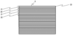
図4は、本実施の形態の立体画像表示装置1を構成する液晶パネル6の模式的な平面図である。
液晶パネル6は、図4に示すように、画素(図示されない)を水平方向に配列してなる水平ライン23を垂直方向に複数並べて構成される。以下、その構成や画像表示機能について説明する。
FIG. 4 is a schematic plan view of the liquid crystal panel 6 constituting the stereoscopic image display device 1 of the present embodiment.
As shown in FIG. 4, the liquid crystal panel 6 is configured by arranging a plurality of horizontal lines 23 in which pixels (not shown) are arranged in the horizontal direction in the vertical direction. Hereinafter, the configuration and the image display function will be described.

図1に示すように、液晶パネル6の画像表示部分においては、水平方向に区切られた第一画像形成領域21と第二画像形成領域22とが設けられている。これら第一画像形成領域21および第二画像形成領域22は、図1に示すように、互いに、実質的に同一の面積を有する領域である。液晶パネル6の画像表示部分において、複数の第一画像形成領域21および第二画像形成領域22は、垂直方向に互い違いに配置されている。   As shown in FIG. 1, in the image display portion of the liquid crystal panel 6, a first image forming region 21 and a second image forming region 22 that are partitioned in the horizontal direction are provided. The first image forming area 21 and the second image forming area 22 are areas having substantially the same area as each other, as shown in FIG. In the image display portion of the liquid crystal panel 6, the plurality of first image forming areas 21 and second image forming areas 22 are alternately arranged in the vertical direction.

そして、図4に示すように、液晶パネル6の第一画像形成領域21と第二画像形成領域22は、垂直方向に連続して並べられた複数の水平ライン23からそれぞれ構成されている。なお、図4において示される液晶パネル6では、第一画像形成領域21と第二画像形成領域22はそれぞれ、連続して並べられた3本の水平ライン23から構成されている。   As shown in FIG. 4, the first image forming area 21 and the second image forming area 22 of the liquid crystal panel 6 are each composed of a plurality of horizontal lines 23 arranged continuously in the vertical direction. In the liquid crystal panel 6 shown in FIG. 4, the first image forming area 21 and the second image forming area 22 are each composed of three horizontal lines 23 arranged in succession.

その結果、液晶パネル6の最上部にある1本目の水平ラインから3本目の水平ラインまでが束ねられて第一画像形成領域21を構成し、4本目の水平ラインから6本目の水平ラインまでが束ねられて第二画像形成領域22を構成し、さらに、7本目の水平ラインから9本目の水平ラインまでが束ねられて第一画像形成領域21を構成し、10本目の水平ラインから12本目の水平ラインまでが束ねられて第二画像形成領域22を構成する。すなわち、3本ずつの水平ライン23を順次束ねて、液晶パネル6では、互い違いに複数の第一画像形成領域21および第二画像形成領域22が形成されている。   As a result, the first horizontal line to the third horizontal line at the top of the liquid crystal panel 6 are bundled to form the first image forming region 21, and the fourth horizontal line to the sixth horizontal line are formed. The second image forming area 22 is bundled to form a first image forming area 21 from the seventh horizontal line to the ninth horizontal line, and the twelfth line from the tenth horizontal line is formed. The second image forming area 22 is configured by bundling up to the horizontal line. That is, three horizontal lines 23 are sequentially bundled, and a plurality of first image forming areas 21 and second image forming areas 22 are alternately formed on the liquid crystal panel 6.

このとき、第一画像形成領域21と第二画像形成領域22とを構成する水平ライン23の本数は3本に限られるわけではなく、複数本から構成することが可能である。例えば、第一画像形成領域21と第二画像形成領域22とを構成する水平ライン23の本数を10本とすることなどが可能である。   At this time, the number of horizontal lines 23 constituting the first image forming area 21 and the second image forming area 22 is not limited to three, and can be constituted by a plurality of lines. For example, the number of horizontal lines 23 constituting the first image forming area 21 and the second image forming area 22 can be set to ten.

その場合、液晶パネル6の最上部にある1本目の水平ラインから10本目の水平ラインまでが束ねられて第一画像形成領域21を構成し、11本目の水平ラインから20本目の水平ラインまでが束ねられて第二画像形成領域22を構成し、さらに、21本目の水平ラインから30本目の水平ラインまでが束ねられて第一画像形成領域21を構成し、31本目の水平ラインから40本目の水平ラインまでが束ねられて第二画像形成領域22を構成する。すなわち、10本ずつの水平ライン23を順次束ねて、液晶パネル6では、互い違いに複数の第一画像形成領域21および第二画像形成領域22が形成されていることになる。   In that case, the first horizontal line to the 10th horizontal line at the top of the liquid crystal panel 6 are bundled to form the first image forming area 21, and the 11th horizontal line to the 20th horizontal line are formed. The second image forming area 22 is bundled to form the first image forming area 21 by bundling from the 21st horizontal line to the 30th horizontal line, and the 40th line from the 31st horizontal line. The second image forming area 22 is configured by bundling up to the horizontal line. That is, ten horizontal lines 23 are sequentially bundled, and a plurality of first image forming areas 21 and second image forming areas 22 are alternately formed in the liquid crystal panel 6.

そして、後述するように、クロストークを低減して液晶ディスプレイ5の視野角を広げる観点から、第一画像形成領域21と第二画像形成領域22とを構成する水平ライン23の本数は選択される。   As will be described later, the number of horizontal lines 23 constituting the first image forming area 21 and the second image forming area 22 is selected from the viewpoint of reducing crosstalk and widening the viewing angle of the liquid crystal display 5. .

立体画像表示装置1の液晶ディスプレイ5の液晶パネル6では、表示される一つのフレーム画像の第一画像形成領域21と第二画像形成領域22とにそれぞれ右目用画像と左目用画像とを表示させる。そして、次の(1)または(2)に示す方法に従い、第一画像形成領域21と第二画像形成領域22との間で右目用画像と左目用画像の入れ替えを行う。
(1)フレーム切り替え毎に右目用画像と左目用画像の入れ替えを行う。
(2)(1)以外の場合であって、フレームの切り替え時に右目用画像と左目用画像の入れ替えおよび直前のフレームで表示された画像の上書きのいずれか一方を行う(尚、入れ替えを行わずにそれぞれが右目用画像と左目用画像を維持し続ける場合は含まない。)。
On the liquid crystal panel 6 of the liquid crystal display 5 of the stereoscopic image display device 1, a right-eye image and a left-eye image are displayed in the first image forming area 21 and the second image forming area 22 of one frame image to be displayed, respectively. . Then, according to the following method (1) or (2), the right-eye image and the left-eye image are exchanged between the first image forming area 21 and the second image forming area 22.
(1) The right-eye image and the left-eye image are switched every time the frame is switched.
(2) In cases other than (1), at the time of frame switching, one of the replacement of the right-eye image and the left-eye image and the overwriting of the image displayed in the immediately preceding frame is performed (not replaced) Does not include the case where each keeps the image for the right eye and the image for the left eye).

尚、図1には示されないが、液晶パネル6の周縁には外枠が配されており、液晶パネル6における第一画像形成領域21および第二画像形成領域22は、この外枠に支持される。   Although not shown in FIG. 1, an outer frame is disposed on the periphery of the liquid crystal panel 6, and the first image forming region 21 and the second image forming region 22 in the liquid crystal panel 6 are supported by the outer frame. The

偏光板8は、液晶ディスプレイ5における観察者側に配置される。この偏光板8には、上述の場合の第一画像形成領域21を透過した画像光、および、第二画像形成領域22を透過した画像光が入射する。そして、これら画像光のうち、偏光軸が透過軸と平行な光を透過し、偏光軸が吸収軸と平行(透過軸に垂直)な光を遮断する。ここで、偏光板8における透過軸の方向は、図1に矢印で示すように、観察者が立体画像表示装置1を見たときの水平方向と平行な方向とすることができる。   The polarizing plate 8 is disposed on the viewer side in the liquid crystal display 5. The image light that has passed through the first image forming area 21 and the image light that has passed through the second image forming area 22 are incident on the polarizing plate 8. Of these image lights, light whose polarization axis is parallel to the transmission axis is transmitted, and light whose polarization axis is parallel to the absorption axis (perpendicular to the transmission axis) is blocked. Here, the direction of the transmission axis in the polarizing plate 8 can be a direction parallel to the horizontal direction when the observer views the stereoscopic image display device 1 as indicated by an arrow in FIG.

光学手段である位相差板4は、図1に示すように、フレネルレンズ3と液晶ディスプレイ5との間に配置される。位相差板4は、第一偏光領域31および第二偏光領域32を有する。位相差板4における第一偏光領域31および第二偏光領域32の位置および大きさは、図1に示すように、液晶パネル6の第一画像形成領域21および第二画像形成領域22の位置および大きさに対応している。   As shown in FIG. 1, the phase difference plate 4 that is an optical means is disposed between the Fresnel lens 3 and the liquid crystal display 5. The phase difference plate 4 has a first polarizing region 31 and a second polarizing region 32. The positions and sizes of the first polarizing region 31 and the second polarizing region 32 in the phase difference plate 4 are the positions of the first image forming region 21 and the second image forming region 22 of the liquid crystal panel 6 as shown in FIG. It corresponds to the size.

そして、上述のように、図4に示す本実施の形態の立体画像表示装置1を構成する液晶パネル6においては、液晶パネル6の画像表示にかかる全水平ラインのうち、上から垂直方向に順次3本ずつの水平ライン23が束ねられて便宜上一つの組を構成している。そして、その束ねられた水平ラインの組のそれぞれに対応するよう、同一面積の第一画像形成領域21と第二画像形成領域22とが設けられている。よって、この位相差板4における第一偏光領域31および第二偏光領域32の位置および大きさは、図1に示すように、液晶パネル6の束ねられた3本の水平ラインの組である第一画像形成領域21および第二画像形成領域22の位置および大きさに対応している。   As described above, in the liquid crystal panel 6 constituting the stereoscopic image display device 1 of the present embodiment shown in FIG. 4, among all the horizontal lines related to the image display of the liquid crystal panel 6, sequentially from top to bottom. Three horizontal lines 23 are bundled to form one set for convenience. Then, the first image forming region 21 and the second image forming region 22 having the same area are provided so as to correspond to each of the bundled horizontal line groups. Therefore, the positions and sizes of the first polarizing region 31 and the second polarizing region 32 in the retardation plate 4 are a set of three horizontal lines bundled in the liquid crystal panel 6 as shown in FIG. This corresponds to the positions and sizes of the one image forming area 21 and the second image forming area 22.

したがって、立体画像表示装置1の使用状態において、ある一つのフレーム画像表示時では、位相板4の第一偏光領域31を透過した光が、偏光板7を通過して、液晶パネル6の第一画像形成領域21に入射する。位相差板4の第二偏光領域32を透過した光が、偏光板7を通過して、第二画像形成領域22に入射する。   Therefore, in the usage state of the stereoscopic image display device 1, when a certain frame image is displayed, the light transmitted through the first polarizing region 31 of the phase plate 4 passes through the polarizing plate 7 and the first of the liquid crystal panel 6. The light enters the image forming area 21. The light transmitted through the second polarizing region 32 of the phase difference plate 4 passes through the polarizing plate 7 and enters the second image forming region 22.

位相差板4の構成については、第一の偏光領域31を、実質的に位相差の無いガラスや樹脂等の部材として構成し、第二の偏光領域32を、入射する直線偏光の偏光方向と対応させて光学軸が水平方向から右上45度方向である1/2波長板として構成することが可能である。また、位相差板4は、第一の偏光領域31を、入射する直線偏光の偏光方向と対応させ、遅相軸が水平方向と水平または垂直である1/2波長板として構成し、併せて、第二の偏光領域32を、光学軸が水平方向から右上45度方向である1/2波長板をとして構成することが可能である。   About the structure of the phase difference plate 4, the 1st polarization area 31 is comprised as members, such as glass and resin which do not have a phase difference substantially, and the 2nd polarization area 32 is made into the polarization direction of the incident linearly polarized light, and Correspondingly, it can be configured as a half-wave plate whose optical axis is 45 degrees from the horizontal direction to the upper right. The retardation plate 4 is configured as a half-wave plate in which the first polarization region 31 is made to correspond to the polarization direction of the incident linearly polarized light, and the slow axis is horizontal or vertical with respect to the horizontal direction. The second polarizing region 32 can be configured as a half-wave plate whose optical axis is 45 degrees from the horizontal direction to the upper right.

位相差板4の構造を上述のようにすることで、直線偏光である入射光に対し、位相差板4からの出射光は、透過する位相差板の領域に従い、光軸が回転されないままの直線偏光となるか、または光軸の90度回転された直線偏光となる。すなわち、位相差板4に入射し、位相差板4の第一偏光領域31から出射する光は光軸が回転されないままの直線偏光となる。一方、第二偏光領域32を出射する光は光軸が90度回転された直線偏光となる。   By making the structure of the phase difference plate 4 as described above, the light emitted from the phase difference plate 4 with respect to the incident light that is linearly polarized light is not rotated according to the region of the phase difference plate that is transmitted. Either linearly polarized light or linearly polarized light rotated by 90 degrees of the optical axis is obtained. That is, the light incident on the phase difference plate 4 and emitted from the first polarization region 31 of the phase difference plate 4 becomes linearly polarized light with the optical axis not rotated. On the other hand, the light emitted from the second polarization region 32 is linearly polarized light whose optical axis is rotated by 90 degrees.

尚、本実施の形態の立体画像表示装置1においては、液晶パネル6の画像表示にかかる全水平ラインの各一本それぞれに対応するよう、第一画像形成領域21と第二画像形成領域22とを設けることも可能である。その場合、位相差板4においても、液晶パネル6の各水平ライン23に対応する第一画像形成領域21および第二画像形成領域22の位置および大きさに対応して、第一偏光領域31および第二偏光領域32が形成される。   In the stereoscopic image display device 1 according to the present embodiment, the first image forming area 21 and the second image forming area 22 correspond to each one of all the horizontal lines related to the image display of the liquid crystal panel 6. It is also possible to provide. In that case, the first polarizing region 31 and the phase difference plate 4 also correspond to the positions and sizes of the first image forming region 21 and the second image forming region 22 corresponding to the horizontal lines 23 of the liquid crystal panel 6. A second polarizing region 32 is formed.

そして、表示される一つのフレーム画像の水平奇数ラインに対応する第一画像形成領域21と、水平偶数ラインに対応する第二画像形成領域22とにそれぞれ、例えば、右目用画像と左目用画像とを表示させ、フレーム切り替え毎に、その右目用画像と左目用画像の表示された水平ラインを交互に入れ替え、右目用画像と左目用画像がそれぞれインターレースしたフレーム画像を表示するよう構成することができる。   Then, for example, an image for the right eye and an image for the left eye are respectively provided in the first image forming area 21 corresponding to the horizontal odd line of the one frame image to be displayed and the second image forming area 22 corresponding to the horizontal even line. Each time the frame is switched, the horizontal lines on which the right-eye image and the left-eye image are displayed are alternately switched, and a frame image in which the right-eye image and the left-eye image are interlaced is displayed. .

しかしながら、その場合、クロストークの問題が顕著となる。
すなわち、立体画像表示装置1の画面を構成する液晶ディスプレイ5の中央鉛直方向からある視野角をもって、観察者50が立体画像表示装置1上の立体画像を観察する場合がある。本来、ある一つのフレーム画像表示時では、位相差板4の第一偏光領域31を透過した光は、液晶パネル6の第一画像形成領域21にのみ入射することが必要である。一方、第二偏光領域32を透過した光は、第二画像形成領域22にのみが入射することが必要である。それに対し、視野角を大きくとった場合、位相差板4の第一偏光領域31を透過した光が液晶パネル6の第二画像形成領域22に入射し、一方、第二偏光領域32を透過した光が、第一画像形成領域21に入射してしまうことがある。
However, in that case, the problem of crosstalk becomes significant.
That is, the observer 50 may observe a stereoscopic image on the stereoscopic image display device 1 with a certain viewing angle from the central vertical direction of the liquid crystal display 5 constituting the screen of the stereoscopic image display device 1. Originally, when a certain frame image is displayed, the light transmitted through the first polarizing region 31 of the phase difference plate 4 needs to be incident only on the first image forming region 21 of the liquid crystal panel 6. On the other hand, the light transmitted through the second polarizing region 32 needs to be incident only on the second image forming region 22. On the other hand, when the viewing angle is large, the light transmitted through the first polarizing region 31 of the phase difference plate 4 is incident on the second image forming region 22 of the liquid crystal panel 6 and is transmitted through the second polarizing region 32. Light may enter the first image forming area 21.

こうしたタイプのクロストークは、位相差板4において位相差特性の異なる第一偏光領域31と第二偏光領域32とが互いに隣接するように設けられていることに起因する。
すなわち、クロストークは立体画像表示装置1の画面の上下方向である視野角以上でもって、観察者50がその画面上の画像を観察する場合に起こりやすい。
This type of crosstalk is caused by the fact that the first polarizing region 31 and the second polarizing region 32 having different phase difference characteristics are provided adjacent to each other in the phase difference plate 4.
That is, crosstalk is likely to occur when the observer 50 observes an image on the screen with a viewing angle that is the vertical direction of the screen of the stereoscopic image display device 1.

このタイプのクロストークは、位相差板4の互いに隣接する第一偏光領域31と第二偏光領域32との境界領域で起こる。したがって、これを低減するためには、位相差板4において第一偏光領域31と隣接する第二偏光領域32との境界領域を減らすことが有効である。   This type of crosstalk occurs in the boundary region between the first polarizing region 31 and the second polarizing region 32 that are adjacent to each other in the retardation plate 4. Therefore, in order to reduce this, it is effective to reduce the boundary region between the first polarizing region 31 and the adjacent second polarizing region 32 in the phase difference plate 4.

例えば、液晶パネル6がフルHD(Full High Definition)仕様に対応し、その水平ラインは1080本であるとする。その場合、上記したように全水平ラインのそれぞれに対応するよう、第一画像形成領域21と第二画像形成領域22とを設けるとすると、それらは互い違いに540個ずつ設けられることになる。その結果、位相差板4では、液晶パネル6の第一画像形成領域21および第二画像形成領域22の位置および大きさに対応するように540個ずつの第一偏光領域31および第二偏光領域32を有することになる。そして、第一偏光領域31と隣接する第二偏光領域32との境界領域は1079カ所形成されることになる。   For example, it is assumed that the liquid crystal panel 6 corresponds to the full HD (Full High Definition) specification and has 1080 horizontal lines. In this case, if the first image forming area 21 and the second image forming area 22 are provided so as to correspond to all the horizontal lines as described above, 540 of them are alternately provided. As a result, the retardation plate 4 has 540 first polarizing regions 31 and second polarizing regions each corresponding to the position and size of the first image forming region 21 and the second image forming region 22 of the liquid crystal panel 6. 32. Then, 1079 boundary regions between the first polarizing region 31 and the adjacent second polarizing region 32 are formed.

そして、観察者50がある視野角をもって立体画像表示装置1の画面を観察する場合、この境界領域のそれぞれでクロストークが発生する。そのクロストークの強度は上記したように全水平ラインのそれぞれに対応するよう、第一画像形成領域21と第二画像形成領域22とを設けた場合に最も高いものとなる。   When the observer 50 observes the screen of the stereoscopic image display device 1 with a certain viewing angle, crosstalk occurs in each of the boundary regions. The strength of the crosstalk becomes highest when the first image forming area 21 and the second image forming area 22 are provided so as to correspond to all the horizontal lines as described above.

それに対し、図1および図2に例示するように、本実施の形態の液晶パネル6の第一画像形成領域21と第二画像形成領域22とが、複数本の水平ライン23から構成される場合を考察する。その場合、位相差板4では、液晶パネル6の第一画像形成領域21および第二画像形成領域22の位置および大きさに対応して、第一偏光領域31および第二偏光領域32が形成される。その結果、第一偏光領域31および第二偏光領域32の面積は、束ねて組にする水平ライン23の本数に従い大きくなる。そうして、位相差板4において、第一偏光領域31と隣接する第二偏光領域32との境界領域を少なくすることができる。   On the other hand, as illustrated in FIGS. 1 and 2, when the first image forming area 21 and the second image forming area 22 of the liquid crystal panel 6 of the present embodiment are configured by a plurality of horizontal lines 23. Is considered. In that case, in the phase difference plate 4, the first polarizing region 31 and the second polarizing region 32 are formed corresponding to the positions and sizes of the first image forming region 21 and the second image forming region 22 of the liquid crystal panel 6. The As a result, the areas of the first polarizing region 31 and the second polarizing region 32 increase according to the number of horizontal lines 23 that are bundled together. Thus, in the phase difference plate 4, the boundary region between the first polarizing region 31 and the adjacent second polarizing region 32 can be reduced.

すなわち、クロストークを発生させる、第一偏光領域31と第二偏光領域32との境界領域が少なくなることから、クロストークの発生は立体画像表示装置1全体としては少なくなる。よって、液晶パネル6の第一画像形成領域21および第二画像形成領域22を形成するために束ねて組にする水平ライン23の本数の増加に従い、クロストークは抑えられる。そして、観察者50はクロストークを感じにくくなる。   That is, since the boundary region between the first polarization region 31 and the second polarization region 32 that generates crosstalk is reduced, the occurrence of crosstalk is reduced as a whole in the stereoscopic image display apparatus 1. Therefore, crosstalk is suppressed as the number of horizontal lines 23 bundled together to form the first image forming area 21 and the second image forming area 22 of the liquid crystal panel 6 increases. And the observer 50 becomes difficult to feel crosstalk.

したがって、本実施の形態の立体画像表示装置1においては、クロストークが低減され、観察可能な視野角が拡大して視野角特性が向上する。
以上から、クロストークを低減するという観点からは、液晶パネル6の第一画像形成領域21および第二画像形成領域22を形成するために、束ねて組にする水平ライン23の本数は、より多いほうが好ましい。
Therefore, in the stereoscopic image display device 1 of the present embodiment, crosstalk is reduced, the observable viewing angle is expanded, and the viewing angle characteristics are improved.
From the above, from the viewpoint of reducing crosstalk, the number of horizontal lines 23 bundled together to form the first image forming area 21 and the second image forming area 22 of the liquid crystal panel 6 is larger. Is preferred.

また、クロストークの低減には、位相差板4の液晶ディスプレイ5に対向する面における第一偏光領域31と第二偏光領域32との境界領域に、遮光部(図示されない)を設けることも有効である。この遮光部は帯状の形状を有し、第一偏光領域31と第二偏光領域32との境界領域に配設されることが好ましい。   In order to reduce crosstalk, it is also effective to provide a light shielding portion (not shown) in the boundary region between the first polarizing region 31 and the second polarizing region 32 on the surface of the retardation plate 4 facing the liquid crystal display 5. It is. This light shielding part has a belt-like shape, and is preferably disposed in a boundary region between the first polarizing region 31 and the second polarizing region 32.

こうした遮光部(図示されない)を設けることにより、位相差板4の第一偏光領域31を出射して、液晶パネルの第一画像形成領域21に入射すべき光のうち、その境界を超えて隣接する第二画像形成領域22に入射する光を吸収して遮ることが可能となる。位相差板4に遮光部を設けることにより、立体画像表示装置1で発生するクロストークを生じにくくさせることが可能となる。   By providing such a light-shielding portion (not shown), light that exits from the first polarizing region 31 of the phase difference plate 4 and enters the first image forming region 21 of the liquid crystal panel is adjacent beyond the boundary. It is possible to absorb and block the light incident on the second image forming area 22. By providing the light shielding portion on the phase difference plate 4, it is possible to make it difficult for crosstalk that occurs in the stereoscopic image display device 1 to occur.

位相差板4における遮光部(図示されない)は、例えば、バインダー樹脂にフィラー成分を分散させたものなどで形成することが好ましい。フィラー成分は、金属粒子およびその酸化物、または顔料、染料を用いる。フィラー成分の色調は、画像光に対して黒色であることが好ましい。上記顔料および染料を分散あるいは溶解させるバインダー樹脂は、公知の樹脂、例えば、アクリル樹脂、ウレタン樹脂、ポリエステル、ノボラック樹脂、ポリイミド、エポキシ樹脂、塩化ビニル・酢酸ビニルコポリマー、ニトロセルロース、または、これらの組み合わせ等を用いることができる。   The light shielding portion (not shown) in the phase difference plate 4 is preferably formed of, for example, a binder resin in which a filler component is dispersed. As the filler component, metal particles and oxides thereof, or pigments and dyes are used. The color tone of the filler component is preferably black with respect to the image light. Binder resins for dispersing or dissolving the pigments and dyes are known resins such as acrylic resins, urethane resins, polyesters, novolac resins, polyimides, epoxy resins, vinyl chloride / vinyl acetate copolymers, nitrocellulose, or combinations thereof. Etc. can be used.

ただし、遮光部は、位相差板4と液晶ディスプレイ5とを透過して観察者50の目に届く画像光の一部を遮光する。クロストークの低減には有効であるが、立体画像表示装置1の画像表示における画面輝度は低下する。例えば、上記したように、全水平ラインのそれぞれに対応するよう、第一画像形成領域21と第二画像形成領域22とを設けた場合、その境界領域ごとに形成が必要とされる帯状の遮光部の数は最大となる。その結果、遮光部の形成による輝度の低下は大きなものとなる。   However, the light shielding portion shields part of the image light that passes through the phase difference plate 4 and the liquid crystal display 5 and reaches the eyes of the observer 50. Although effective in reducing the crosstalk, the screen brightness in the image display of the stereoscopic image display device 1 is lowered. For example, as described above, when the first image forming area 21 and the second image forming area 22 are provided so as to correspond to all the horizontal lines, a strip-shaped light shielding that needs to be formed for each boundary area. The number of parts is maximized. As a result, the decrease in luminance due to the formation of the light shielding portion is significant.

遮光部の形成は有効なものの、その形成数を少なくするよう、位相差板4を構成することが好ましい。
したがって、遮光部の形成数を低減するという観点からも、第一画像形成領域21および第二画像形成領域22を形成するよう、束ねて組にする水平ライン23の本数は、多いほうが好ましいことになる。
Although the formation of the light shielding portions is effective, it is preferable to configure the phase difference plate 4 so as to reduce the number of the light shielding portions.
Therefore, from the viewpoint of reducing the number of light-shielding portions formed, it is preferable that the number of horizontal lines 23 bundled together to form the first image forming region 21 and the second image forming region 22 is larger. Become.

しかしながら、その一つの組にされる水平ライン23の本数を無制限に増大させることにも問題がある。すなわち、観察者にとって、自然な画像が得られないという問題を引き起こす可能性がある。   However, there is a problem in increasing the number of horizontal lines 23 in one set without limitation. That is, it may cause a problem that a natural image cannot be obtained for the observer.

以上から、本実施の形態の立体画像表示装置1においては、クロストークの低減と画面輝度の低下抑制の観点と、観察者50に自然な立体画像を提供するという観点から、液晶パネル6の第一画像形成領域21と第二画像形成領域22とを構成するために束ねて一つの組にされる水平ライン23の本数を選択することが好ましい。そして、それに対応する位置と大きさで、位相差板4の第一偏光領域31および第二偏光領域32を形成することが好ましい。   From the above, in the stereoscopic image display device 1 of the present embodiment, the first aspect of the liquid crystal panel 6 is from the viewpoint of reducing crosstalk and suppressing reduction in screen luminance and providing a natural stereoscopic image to the viewer 50. It is preferable to select the number of horizontal lines 23 that are bundled together to form one image forming area 21 and second image forming area 22. And it is preferable to form the 1st polarizing region 31 and the 2nd polarizing region 32 of the phase difference plate 4 by the position and magnitude | size corresponding to it.

そして、鋭意検討の結果から、液晶パネル6の第一画像形成領域21と第二画像形成領域22とはそれぞれ、液晶パネル6の垂直方向に連続して並べられた2本から60本の水平ライン23からなる画像形成領域であることが好ましいことがわかった。   As a result of intensive studies, the first image forming area 21 and the second image forming area 22 of the liquid crystal panel 6 are respectively arranged in two to 60 horizontal lines that are continuously arranged in the vertical direction of the liquid crystal panel 6. It was found that an image forming area consisting of 23 is preferable.

さらに、液晶パネル6の第一画像形成領域21と第二画像形成領域22とはそれぞれ、液晶パネル6の垂直方向に連続して並べられた3本から30本の水平ライン23からなる画像形成領域であることがより好ましく、5本から15本の水平ライン23からなる画像形成領域であることが最も好ましいことがわかった。そして、それに対応する位置と大きさで位相差板4の第一偏光領域31および第二偏光領域32を形成することが当然に好ましい。   Further, each of the first image forming area 21 and the second image forming area 22 of the liquid crystal panel 6 is an image forming area composed of three to thirty horizontal lines 23 arranged continuously in the vertical direction of the liquid crystal panel 6. It is more preferable that the image forming area is composed of 5 to 15 horizontal lines 23. Of course, it is preferable to form the first polarizing region 31 and the second polarizing region 32 of the phase difference plate 4 at positions and sizes corresponding thereto.

以上、本実施の形態の立体画像表示装置1の主な構成について説明したが、次に図1および図2を用いて、本実施の形態の立体画像表示装置1によって立体画像を形成する方法および観察者がその立体画像を観察する方法について説明する。   The main configuration of the stereoscopic image display device 1 of the present embodiment has been described above. Next, a method of forming a stereoscopic image by the stereoscopic image display device 1 of the present embodiment and FIG. 1 and FIG. A method for the observer to observe the stereoscopic image will be described.

観察者50が、立体画像表示装置1により立体画像を観察する場合、制御装置12に制御され、ある一つのフレーム画像が表示される。その時、液晶ディスプレイ5には、右目用画像および左目用画像が同時に形成される。すなわち、液晶ディスプレイ5の第一画像形成領域21および第二画像形成領域22には、偏光板7、8および液晶パネル5の作用によって、例えば、右目用画像および左目用画像がそれぞれ形成される。   When the observer 50 observes a stereoscopic image with the stereoscopic image display device 1, the observer 50 controls the display device to display a single frame image. At that time, a right-eye image and a left-eye image are simultaneously formed on the liquid crystal display 5. That is, for example, a right-eye image and a left-eye image are formed in the first image forming area 21 and the second image forming area 22 of the liquid crystal display 5 by the action of the polarizing plates 7 and 8 and the liquid crystal panel 5, respectively.

液晶ディスプレイ5での右目用画像および左目用画像の形成に対応し、制御装置12に制御され、バックライト2からは、光源の第1列を構成する2つの偏光光源13a、13bから直線偏光が射出される。偏光光源13a、13bから射出される直線偏光の偏光方向は、中央を境にして、図1において矢印で示される偏光特性を有する。すなわち、図1に示すように、左右に並べられた偏光光源13aと偏光光源13bとからは、互いに偏光方向が直交する直線偏光が、フレネルレンズ3や位相差板4に向かって射出される。   Corresponding to the formation of the image for the right eye and the image for the left eye on the liquid crystal display 5, the control device 12 controls the linearly polarized light from the two polarized light sources 13a and 13b constituting the first row of light sources. It is injected. The polarization direction of linearly polarized light emitted from the polarized light sources 13a and 13b has a polarization characteristic indicated by an arrow in FIG. That is, as shown in FIG. 1, linearly polarized light whose polarization directions are orthogonal to each other is emitted toward the Fresnel lens 3 and the phase difference plate 4 from the polarized light source 13 a and the polarized light source 13 b arranged side by side.

そして、図2に示すように、バックライト2の偏光光源13aから射出した光は、上述したフレネルレンズ3の作用によって観察者50の右目41aの有る領域に向かう光となる。そして、位相差板4と液晶ディスプレイ5を通過した場合、所定の観察位置に位置する観察者の右目41aに入射する。一方、偏光光源13bから射出した光は、上述したフレネルレンズ3の作用によって観察者の左目41bの有る領域に向かう光となる。そして、位相差板4と液晶ディスプレイ5を通過した場合、所定の観察位置に位置する観察者の左目41bに入射する。   As shown in FIG. 2, the light emitted from the polarized light source 13 a of the backlight 2 becomes light directed to a region where the right eye 41 a of the observer 50 is present due to the action of the Fresnel lens 3 described above. When the light passes through the phase difference plate 4 and the liquid crystal display 5, the light enters the viewer's right eye 41 a located at a predetermined observation position. On the other hand, the light emitted from the polarized light source 13b becomes light directed to a region where the left eye 41b of the observer is present by the action of the Fresnel lens 3 described above. When the light passes through the phase difference plate 4 and the liquid crystal display 5, the light enters the left eye 41 b of the observer located at a predetermined observation position.

このとき、上述のように、位相差板4に入射し、位相差板4の第一偏光領域31から出射する光は光軸が回転されないままの直線偏光となり、第二偏光領域32から出射する光は光軸の90度回転された直線偏光となる。   At this time, as described above, the light incident on the phase difference plate 4 and emitted from the first polarization region 31 of the phase difference plate 4 becomes linearly polarized light without rotating the optical axis and is emitted from the second polarization region 32. The light becomes linearly polarized light rotated by 90 degrees on the optical axis.

したがって、偏光光源13aから射出した水平方向と垂直な偏光方向の直線偏光は、フレネルレンズ3と位相差板4を通過し、液晶ディスプレイ5を照射する。液晶ディスプレイ5の偏光板7の透過軸は、水平方向と垂直な方向に設定されている。したがって、位相差板4を出射した光のうち、第一偏光領域31から出射した光は、偏光板7を通過することができ、液晶パネル6の第一画像形成領域21に入射する。一方、位相差板4の第二偏光領域32を出射した光は、水平方向と平行な方向に偏光方向を有する直線偏光となっており、偏光板7によって遮断され、液晶パネル6に到達することはできない。   Therefore, the linearly polarized light having a polarization direction perpendicular to the horizontal direction emitted from the polarized light source 13 a passes through the Fresnel lens 3 and the phase difference plate 4 and irradiates the liquid crystal display 5. The transmission axis of the polarizing plate 7 of the liquid crystal display 5 is set in a direction perpendicular to the horizontal direction. Therefore, out of the light emitted from the phase difference plate 4, the light emitted from the first polarizing region 31 can pass through the polarizing plate 7 and is incident on the first image forming region 21 of the liquid crystal panel 6. On the other hand, the light emitted from the second polarizing region 32 of the phase difference plate 4 is linearly polarized light having a polarization direction parallel to the horizontal direction, and is blocked by the polarizing plate 7 and reaches the liquid crystal panel 6. I can't.

液晶ディスプレイ5の第一画像形成領域21では、上述のように、右目用画像が形成され、第二画像形成領域22では、左目用画像が形成されている。したがって、位相差板4の第一偏光領域31を出射した光は、液晶ディスプレイ5の第一画像形成領域21に入射し、そこから透過する光は右目用画像の画像光(以下、「右目用画像光」と略称する)となって、観察者の右目41aに到達する。このとき、偏光光源13aから出射し、位相差板4の第二偏光領域32を通過した光は、上述したように、観察者50の右目41aに到達することは無い。   As described above, the right-eye image is formed in the first image forming area 21 of the liquid crystal display 5, and the left-eye image is formed in the second image forming area 22. Therefore, the light emitted from the first polarizing region 31 of the phase difference plate 4 enters the first image forming region 21 of the liquid crystal display 5, and the light transmitted therethrough is image light for the right eye image (hereinafter “right eye image”). Abbreviated as “image light”) and reaches the right eye 41a of the observer. At this time, the light emitted from the polarization light source 13a and having passed through the second polarization region 32 of the phase difference plate 4 does not reach the right eye 41a of the observer 50 as described above.

また、偏光光源13bから射出した水平方向と平行な偏光方向の直線偏光は、フレネルレンズ3と位相差板4を通過し、液晶ディスプレイ5を照射する。このとき、偏光板7の透過軸は、水平方向と垂直な方向に設定されている。したがって、位相差板4を出射した光のうち、第一偏光領域31から出射した光は、偏光板7によって遮断され、液晶パネル6に到達することはできない。
一方、位相差板4の第二偏光領域32を出射した光は、水平方向と垂直な方向に偏光方向を有する直線偏光となっており、偏光板7を通過することができ、液晶パネル6の第二画像形成領域22に入射する。
Further, linearly polarized light having a polarization direction parallel to the horizontal direction emitted from the polarized light source 13 b passes through the Fresnel lens 3 and the phase difference plate 4 and irradiates the liquid crystal display 5. At this time, the transmission axis of the polarizing plate 7 is set in a direction perpendicular to the horizontal direction. Therefore, the light emitted from the first polarizing region 31 out of the light emitted from the phase difference plate 4 is blocked by the polarizing plate 7 and cannot reach the liquid crystal panel 6.
On the other hand, the light emitted from the second polarization region 32 of the phase difference plate 4 is linearly polarized light having a polarization direction in a direction perpendicular to the horizontal direction, and can pass through the polarizing plate 7. The light enters the second image forming area 22.

液晶ディスプレイ5の第一画像形成領域21では、上述のように、右目用画像が形成され、第二画像形成領域22では、左目用画像が形成されている。したがって、位相差板4の第二偏光領域32を出射した光は、液晶ディスプレイ5の第二画像形成領域21に入射し、そこから透過する光は左目用画像の画像光(以下、「左目用画像光」と略称する)となって、観察者の左目41bに到達する。このとき、偏光光源13bから出射し、位相差板4の第一偏光領域31を通過した光は、上述したように、観察者50の左目41bに到達することは無い。   As described above, the right-eye image is formed in the first image forming area 21 of the liquid crystal display 5, and the left-eye image is formed in the second image forming area 22. Therefore, the light emitted from the second polarizing region 32 of the phase difference plate 4 enters the second image forming region 21 of the liquid crystal display 5, and the light transmitted therethrough is the image light of the left eye image (hereinafter referred to as “left eye image”). Abbreviated as “image light”) and reaches the left eye 41b of the observer. At this time, the light emitted from the polarized light source 13b and having passed through the first polarizing region 31 of the phase difference plate 4 does not reach the left eye 41b of the observer 50 as described above.

こうして、観察者50は、立体画像表示装置1の画像を観察するに際し、右目では右目用画像光だけを観察することができ、左目では左目用画像光だけを観察することができることになる。したがって、観察者50は、これら右目用画像光および左目用画像光を立体画像として認識することができる。   Thus, the observer 50 can observe only the right eye image light with the right eye and the left eye only with the left eye image when observing the image of the stereoscopic image display device 1. Therefore, the observer 50 can recognize these right-eye image light and left-eye image light as a stereoscopic image.

次に、観察者50が、立体画像表示装置1により立体画像を観察するに際し、上述のように、フレームの切り替えにともなう画像領域の入れ替えが行われた場合について説明する。すなわち、制御装置12による制御によって、ある一つのフレームにおいて、液晶ディスプレイ5における第一画像形成領域21に左目用画像が形成され、第二画像形成領域22に右目用画像が形成されるようになった場合について説明する。   Next, a description will be given of a case where, when the observer 50 observes a stereoscopic image with the stereoscopic image display device 1, the image area is switched as the frame is switched as described above. That is, under the control of the control device 12, the left-eye image is formed in the first image forming area 21 in the liquid crystal display 5 and the right-eye image is formed in the second image forming area 22 in a certain frame. The case will be described.

液晶ディスプレイ5において、フレームの切り替えにともなう画像領域の入れ替えが行われた場合、制御装置12に制御され、バックライト2における使用する偏光光源の列の切り替えが行われる。すなわち、右目用画像と左目用画像の形成領域の入れ替えに際し、光源の切り替えが行われ、光源の第1列に代わって、第2列が使用されるようになる。その結果、第2列を構成する2つの偏光光源14a、14bから直線偏光が射出されるようになる。   In the liquid crystal display 5, when the image area is switched along with the frame switching, the control device 12 controls the polarization light source column used in the backlight 2 to be switched. That is, when the formation area of the right eye image and the left eye image is switched, the light source is switched, and the second column is used instead of the first column of the light source. As a result, linearly polarized light is emitted from the two polarized light sources 14a and 14b constituting the second row.

そして、偏光光源14a、14bから射出される直線偏光の偏光方向は、図1において矢印で示される偏光特性を有し、互いに偏光方向が直交する直線偏光が、フレネルレンズ3や位相差板4に向かって射出される。   The polarization direction of the linearly polarized light emitted from the polarized light sources 14a and 14b has the polarization characteristics indicated by arrows in FIG. 1, and the linearly polarized light whose polarization directions are orthogonal to each other is applied to the Fresnel lens 3 and the phase difference plate 4. It is injected towards.

そして、上述した偏光光源の第1列を使用する場合と同様、偏光光源14aから射出した光は、上述したフレネルレンズ3の作用によって観察者50の右目41aの有る領域に向かう光となる。そして、位相差板4と液晶ディスプレイ5を通過した場合、所定の観察位置に位置する観察者の右目41aに入射する。一方、偏光光源14bから射出した光は、上述したフレネルレンズ3の作用によって観察者の左目41bの有る領域に向かう光となる。そして、位相差板4と液晶ディスプレイ5を通過した場合、所定の観察位置に位置する観察者の左目41bに入射する。   As in the case of using the first column of the polarized light source described above, the light emitted from the polarized light source 14a becomes light directed to the region where the right eye 41a of the observer 50 is located by the action of the Fresnel lens 3 described above. When the light passes through the phase difference plate 4 and the liquid crystal display 5, the light enters the viewer's right eye 41 a located at a predetermined observation position. On the other hand, the light emitted from the polarized light source 14b becomes light directed to a region where the left eye 41b of the observer is present by the action of the Fresnel lens 3 described above. When the light passes through the phase difference plate 4 and the liquid crystal display 5, the light enters the left eye 41 b of the observer located at a predetermined observation position.

このとき、上述のように、位相差板4に入射し、位相差板4の第一偏光領域31から出射する光は光軸が回転されないままの直線偏光となり、第二偏光領域32から出射する光は光軸の90度回転された直線偏光となる。   At this time, as described above, the light incident on the phase difference plate 4 and emitted from the first polarization region 31 of the phase difference plate 4 becomes linearly polarized light without rotating the optical axis and is emitted from the second polarization region 32. The light becomes linearly polarized light rotated by 90 degrees on the optical axis.

したがって、偏光光源14aから射出した水平方向と水平な偏光方向の直線偏光は、フレネルレンズ3と位相差板4を通過し、液晶ディスプレイ5を照射する。このとき、偏光板7の透過軸は、水平方向と垂直な方向に設定されている。したがって、第一偏光領域31から出射した光は、偏光板7によって遮断され、液晶パネル6に到達することはできない。一方、位相差板4を出射した光のうち、位相差板4の第二偏光領域32を出射した光は、水平方向と垂直な方向に偏光方向を有する直線偏光となっており、偏光板7を通過することができ、液晶パネル6の第二画像形成領域22に入射する。   Therefore, the linearly polarized light in the horizontal direction and the horizontal polarization direction emitted from the polarized light source 14 a passes through the Fresnel lens 3 and the phase difference plate 4 and irradiates the liquid crystal display 5. At this time, the transmission axis of the polarizing plate 7 is set in a direction perpendicular to the horizontal direction. Therefore, the light emitted from the first polarizing region 31 is blocked by the polarizing plate 7 and cannot reach the liquid crystal panel 6. On the other hand, out of the light emitted from the phase difference plate 4, the light emitted from the second polarization region 32 of the phase difference plate 4 is linearly polarized light having a polarization direction in a direction perpendicular to the horizontal direction. And enters the second image forming region 22 of the liquid crystal panel 6.

液晶ディスプレイ5の第一画像形成領域21では、上述のように、左目用画像が形成され、第二画像形成領域22では、右目用画像が形成されている。したがって、位相差板4の第二偏光領域32を出射した光は、液晶ディスプレイ5の第二画像形成領域22に入射し、そこから透過する光は右目用画像光となって、観察者の右目41aに到達する。このとき、偏光光源14aから出射し、位相差板4の第一偏光領域31を通過した光は、上述したように、観察者50の右目41aに到達することは無い。   As described above, the left-eye image is formed in the first image forming area 21 of the liquid crystal display 5, and the right-eye image is formed in the second image forming area 22. Therefore, the light emitted from the second polarizing region 32 of the phase difference plate 4 enters the second image forming region 22 of the liquid crystal display 5, and the light transmitted there from becomes right-eye image light, which is the right eye of the observer. 41a is reached. At this time, the light emitted from the polarized light source 14a and having passed through the first polarizing region 31 of the phase difference plate 4 does not reach the right eye 41a of the observer 50 as described above.

また、偏光光源14bから射出した水平方向と垂直な偏光方向の直線偏光は、フレネルレンズ3と位相差板4を通過し、液晶ディスプレイ5を照射する。このとき、偏光板7の透過軸は、水平方向と垂直な方向に設定されている。したがって、位相差板4を出射した光のうち、第一偏光領域31から出射した光は、偏光板7を通過することができ、液晶パネル6の第一画像形成領域21に入射する。
一方、位相差板4の第二偏光領域32を出射した光は、水平方向と平行な方向に偏光方向を有する直線偏光となっており、偏光板7によって遮断され、液晶パネル6に到達することはできない。
Further, linearly polarized light having a polarization direction perpendicular to the horizontal direction emitted from the polarized light source 14 b passes through the Fresnel lens 3 and the phase difference plate 4 and irradiates the liquid crystal display 5. At this time, the transmission axis of the polarizing plate 7 is set in a direction perpendicular to the horizontal direction. Therefore, out of the light emitted from the phase difference plate 4, the light emitted from the first polarizing region 31 can pass through the polarizing plate 7 and is incident on the first image forming region 21 of the liquid crystal panel 6.
On the other hand, the light emitted from the second polarizing region 32 of the phase difference plate 4 is linearly polarized light having a polarization direction parallel to the horizontal direction, and is blocked by the polarizing plate 7 and reaches the liquid crystal panel 6. I can't.

液晶ディスプレイ5の第一画像形成領域21では、上述のように、左目用画像が形成され、第二画像形成領域22では、右目用画像が形成されている。したがって、位相差板4の第一偏光領域31を出射した光は、液晶ディスプレイ5の第一画像形成領域21に入射し、そこから透過する光は左目用画像光となって、観察者の左目41bに到達する。このとき、偏光光源14bから出射し、位相差板4の第二偏光領域32を通過した光は、上述したように、観察者50の左目41bに到達することは無い。   As described above, the left-eye image is formed in the first image forming area 21 of the liquid crystal display 5, and the right-eye image is formed in the second image forming area 22. Therefore, the light emitted from the first polarizing region 31 of the phase difference plate 4 is incident on the first image forming region 21 of the liquid crystal display 5, and the light transmitted there from becomes the left-eye image light, and the left eye of the observer 41b is reached. At this time, the light emitted from the polarized light source 14b and having passed through the second polarization region 32 of the phase difference plate 4 does not reach the left eye 41b of the observer 50 as described above.

こうして、観察者50は、立体画像表示装置1の画像を観察するに際し、右目では右目用画像光だけを観察することができ、左目では左目用画像光だけを観察することができることになる。したがって、観察者50は、これら右目用画像光および左目用画像光を立体画像として認識することができる。   Thus, the observer 50 can observe only the right eye image light with the right eye and the left eye only with the left eye image when observing the image of the stereoscopic image display device 1. Therefore, the observer 50 can recognize these right-eye image light and left-eye image light as a stereoscopic image.

以上のように、液晶ディスプレイ5でのフレームの切り替えにともなう画像領域の入れ替えに同期させて、バックライト2のから出射される左目用の光と右目用の光との間で、変更の状態を交互に入れ替えできるように構成する。こうすることにより、液晶ディスプレイ5において、フレーム切り替えに伴い右目用および左目用画像を形成する領域が入れ替わる画像領域の入れ替えが行われたとしても、観察者50は、右目では右目用画像光だけを観察することができ、左目では左目用画像光だけを観察することができることになる。よって、観察者50は、常に、これら右目用画像光および左目用画像光を立体画像として認識することができる。   As described above, the state of change is changed between the light for the left eye and the light for the right eye emitted from the backlight 2 in synchronization with the replacement of the image areas accompanying the switching of the frames on the liquid crystal display 5. It is configured so that it can be switched alternately. By doing so, even if the image areas are switched in which the areas for forming the right-eye image and the left-eye image are switched as the frame is switched in the liquid crystal display 5, the observer 50 receives only the right-eye image light in the right eye. The left eye can only observe the image light for the left eye. Therefore, the observer 50 can always recognize these right-eye image light and left-eye image light as a stereoscopic image.

したがって、従来の立体画像表示装置においては、右目用および左目用画像を形成する画像領域が固定されていたため、垂直解像度が半減するなど、解像度が低下する問題があったが、本実施の形態の立体画像表示装置1は解像度を全く減じることなく、液晶ディスプレイ5の性能をフルに発揮させたフル解像度での表示が可能となる。   Therefore, in the conventional stereoscopic image display device, since the image area for forming the right eye image and the left eye image is fixed, there is a problem that the resolution is lowered, for example, the vertical resolution is halved. The stereoscopic image display device 1 can display at a full resolution with the full performance of the liquid crystal display 5 without reducing the resolution at all.

また、従来の立体画像表示装置においては、常に左右の目の映像のいずれか一方しか表示されず、立体を認識する場合の時間差が生じてしまう場合があったが、本実施の形態の立体画像表示装置1では、常に左右の絵目の映像が表示されていることから、観視者の疲労感を軽減することができる。また、激しい動きをしている立体画像の場合におきる左右の映像のずれに伴う立体視の違和感を生じさせないという効果もある。   In addition, in the conventional stereoscopic image display device, only one of the left and right eye images is always displayed, and there may be a time difference when recognizing a stereoscopic image. Since the display device 1 always displays images of the left and right pictures, it is possible to reduce the fatigue of the viewer. In addition, there is also an effect that the sense of incongruity of stereoscopic vision caused by the shift of the left and right images that occurs in the case of a stereoscopic image that moves vigorously is not caused.

次に、第1実施形態の立体画像表示装置1における立体画像の形成とフレーム周波数との関係について説明する。
立体画像表示装置1の液晶ディスプレイ5は、一つのフレーム画像上で右目用画像と左目用画像とを同時に形成する。すなわち、図1に示す液晶ディスプレイ5の液晶パネル6の第一画像形成領域21と第二画像形成領域22とにそれぞれ右目用画像と左目用画像とを形成する。
Next, the relationship between the formation of a stereoscopic image and the frame frequency in the stereoscopic image display device 1 of the first embodiment will be described.
The liquid crystal display 5 of the stereoscopic image display device 1 simultaneously forms a right-eye image and a left-eye image on one frame image. That is, a right eye image and a left eye image are formed in the first image forming area 21 and the second image forming area 22 of the liquid crystal panel 6 of the liquid crystal display 5 shown in FIG.

そして、フレーム切り替えに毎に、その右目用画像と左目用画像の表示された画像形成領域を交互に入れ替え、右目用画像と左目用画像がそれぞれ互い違いに配置されたフレーム画像を表示することができるように構成されている。しかしながら、フレーム画像の切り替え時に発生する、右目用画像と左目用画像との混在によるクロストークの影響を低減するため、一つのフレーム画像上に右目用画像と左目用画像とを同時に表示した後、次のフレームでは画像領域の入れ替えを行なわず、そのまま上書きをするように制御し、上書き画像を少なくとも次の一フレーム期間、液晶ディスプレイ5に表示させることができる。   Then, each time the frame is switched, the image forming areas where the right-eye image and the left-eye image are displayed are alternately switched, and a frame image in which the right-eye image and the left-eye image are alternately arranged can be displayed. It is configured as follows. However, in order to reduce the influence of crosstalk caused by the mixture of the right-eye image and the left-eye image that occurs when switching the frame image, after displaying the right-eye image and the left-eye image simultaneously on one frame image, In the next frame, the image area is not replaced, and control is performed so that the image is overwritten, and the overwritten image can be displayed on the liquid crystal display 5 for at least the next one frame period.

その場合、制御装置12は、バックライト2全体の点滅を同時に制御することができる。すなわち、一つのフレーム画像を表示する期間はバックライト2の上下いずれかの列を点灯させておき、そしてその前後にある、右目用画像と左目用画像の表示された画像形成領域を入れ替えるフレームではバックライト2全体を消灯する、または適当に輝度を低下させるように制御する。こうすることで、右目用画像と左目用画像の残像と画像領域の入れ替えに基づく上述のクロストークを、観察者50に感知されなくすることが可能となる。   In that case, the control device 12 can simultaneously control blinking of the entire backlight 2. That is, in a period in which one frame image is displayed, either one of the upper and lower columns of the backlight 2 is turned on, and in the frame in which the image forming areas in which the right-eye image and the left-eye image are displayed are replaced before and after that, Control is performed so that the entire backlight 2 is turned off or the luminance is appropriately reduced. By doing so, it is possible to prevent the observer 50 from detecting the above-described crosstalk based on the replacement of the afterimage and the image area of the right-eye image and the left-eye image.

このように、一つのフレーム画像上に右目用画像と左目用画像とを同時に表示した後、次のフレームでは画像領域の入れ替えを行なわず、そのまま上書きをする場合、最適なフレーム周波数の設定を行うことにより、表示画像のスムーズさが失われることは無い。また、バックライト2においては、フレーム毎に行われるバックライトの点滅が観察者50に感知され、そのことに起因するフリッカーを観察者が感じる懸念もなくなる。   As described above, when the right-eye image and the left-eye image are simultaneously displayed on one frame image, when the next frame is not overwritten and is overwritten as it is, the optimum frame frequency is set. Thus, the smoothness of the display image is not lost. In the backlight 2, the blinking of the backlight performed for each frame is detected by the observer 50, and there is no concern that the observer feels flicker due to the blinking.

したがって、液晶ディスプレイ5におけるフレーム周波数を、例えば、フレーム周波数は120Hz以上とすることが好ましい。そうすることにより、一つのフレーム画像上に右目用画像と左目用画像とを同時に表示した後、次のフレームでは画像領域の入れ替えを行なわず、そのまま上書きをする場合でも、フレーム周波数60Hzに対応する立体画像の形成が可能となり、画像の切り替え可能な回数も多くなり、また、フリッカーが観察者50によって感じられる懸念はない。さらに、上述のバックライト2の点滅に由来するフリッカーも観察者50に感知されなくなる。したがって、本実施の形態の立体画像表示装置1により提供される表示画像も自然なものとなる。   Therefore, the frame frequency in the liquid crystal display 5 is preferably set to 120 Hz or higher, for example. By doing so, after the image for the right eye and the image for the left eye are simultaneously displayed on one frame image, the image area is not replaced in the next frame, and the frame frequency corresponds to 60 Hz even when overwriting as it is. A stereoscopic image can be formed, the number of times that the image can be switched is increased, and there is no concern that flicker is felt by the observer 50. Further, the flicker resulting from the blinking of the backlight 2 is not perceived by the observer 50. Therefore, the display image provided by the stereoscopic image display device 1 of the present embodiment is also natural.

さらに、本実施の形態の立体画像表示装置1においては、制御装置12によって制御される液晶ディスプレイ5におけるフレーム周波数を240Hzとすることも可能である。その場合、制御装置12によって、フレーム切り替えによって一つのフレーム画像上に右目用画像と左目用画像とを同時に表示した後、引き続く3回のフレームでは画像領域の入れ替えを行なわず、そのまま上書きをするように制御することができる。すなわち、画像領域の入れ替えの後に続く3フレーム期間、上書き画像を液晶ディスプレイ5に表示させ、立体画像の形成をすることが可能となる。   Furthermore, in the stereoscopic image display device 1 of the present embodiment, the frame frequency in the liquid crystal display 5 controlled by the control device 12 can be set to 240 Hz. In that case, the controller 12 displays the right-eye image and the left-eye image simultaneously on one frame image by switching the frames, and then overwrites the image area as it is without replacing the image area in the subsequent three frames. Can be controlled. That is, it is possible to form a stereoscopic image by displaying the overwritten image on the liquid crystal display 5 for a period of three frames following the replacement of the image areas.

そのような制御を行う場合、最初の1フレーム期間である1/240秒間だけ、バックライト2を消灯させ、その後の上書き画像表示を行う、3フレーム期間である3/240秒間は、バックライト2を点灯させることができる。その結果、上述の120Hzでの駆動で可能とされた、フレーム毎に、液晶ディスプレイ5における右目用画像と左目用画像の表示領域の入れ替えとそのままの上書きとを繰り返すというパターンに比べて、バックライトが消灯している期間を減らすことができる。その結果、立体画像表示装置1における立体表示画像の輝度をより向上することが可能となる。   When such control is performed, the backlight 2 is turned off only for 1/240 seconds that is the first one frame period, and then the overwriting image display is performed, and the backlight 2 is displayed for 3/240 seconds that is the three frame period. Can be lit. As a result, the backlight is compared with the pattern in which the display area of the right-eye image and the left-eye image on the liquid crystal display 5 is exchanged and overwritten as it is for each frame, which is enabled by driving at 120 Hz. The period during which is turned off can be reduced. As a result, the brightness of the stereoscopic display image in the stereoscopic image display apparatus 1 can be further improved.

以上のように、液晶ディスプレイ5におけるフレーム周波数を120Hzや240Hzなど向上させることにより、自然で高画質な立体表示画像表示を楽しむことが可能となる。   As described above, by improving the frame frequency of the liquid crystal display 5 such as 120 Hz or 240 Hz, it becomes possible to enjoy natural and high-quality stereoscopic display image display.

<実施の形態2>
本発明の第2実施形態の立体画像表示装置61は、立体画像の観察に好適な視点(観察位置)が1つ形成されるよう構成される。上述した同様の第1実施形態の立体画像表示装置1の別の例となる。
以下、図面を用いて、本発明の第2実施形態の立体画像表示装置61を説明するが、上述した第1実施形態の立体画像表示装置1と共通する構成要素については、共通する符号を用いて説明する。
<Embodiment 2>
The stereoscopic image display device 61 according to the second embodiment of the present invention is configured such that one viewpoint (observation position) suitable for observation of a stereoscopic image is formed. It becomes another example of the same three-dimensional image display apparatus 1 of 1st Embodiment mentioned above.
Hereinafter, the stereoscopic image display device 61 according to the second embodiment of the present invention will be described with reference to the drawings. The same reference numerals are used for the components common to the above-described stereoscopic image display device 1 according to the first embodiment. I will explain.

図5は、本発明の第2実施形態の立体画像表示装置61の要部構成を説明する模式的な分解斜視図である。   FIG. 5 is a schematic exploded perspective view for explaining a main configuration of a stereoscopic image display device 61 according to the second embodiment of the present invention.

図5に示すように、立体画像表示装置61は、バックライト62と、集光レンズであるフレネルレンズ3と、光学手段である位相差板74と、液晶ディスプレイ5とをこの順で備える。そして、バックライト62と液晶ディスプレイ5の駆動をそれぞれ制御する制御装置12を備える。これらは図示されない筐体に収容される。そして、図1に示すように、立体画像を観察する観察者80は液晶ディスプレイ5の前面側から画面上の立体画像を観察する。   As shown in FIG. 5, the stereoscopic image display device 61 includes a backlight 62, a Fresnel lens 3 that is a condenser lens, a retardation plate 74 that is an optical unit, and a liquid crystal display 5 in this order. And the control apparatus 12 which respectively controls the drive of the backlight 62 and the liquid crystal display 5 is provided. These are housed in a housing (not shown). As shown in FIG. 1, the observer 80 who observes the stereoscopic image observes the stereoscopic image on the screen from the front side of the liquid crystal display 5.

そして、第2実施形態の立体画像表示装置61は、特に、バックライト62と位相差板74の構造が上述の第1実施形態の立体画像表示装置1と異なっている。フレネルレンズ3、液晶ディスプレイ5および制御装置12など、その他の主要な構成要素については、上述の立体画像表示装置1と同様の構造を有し、同様に機能する。したがって、主要部の構成について、重複する説明は省略する。   The stereoscopic image display device 61 according to the second embodiment is particularly different from the stereoscopic image display device 1 according to the first embodiment described above in the structures of the backlight 62 and the phase difference plate 74. Other main components such as the Fresnel lens 3, the liquid crystal display 5, and the control device 12 have the same structure as the above-described stereoscopic image display device 1 and function in the same manner. Therefore, the description which overlaps about the structure of the principal part is abbreviate | omitted.

立体画像表示装置61のバックライト62は、上述の立体画像表示装置1と同様の配列で、4つの偏光光源63a、63b、64a、64bを有する。これらは、いずれも左右いずれかの円偏光を放射する偏光光源である。これら偏光光源は、例えばLEDなど、白色の無偏光を放射する点光源の上に、直線偏光板と1/4波長板とを重ねて設けることにより構成することができる。   The backlight 62 of the stereoscopic image display device 61 has the same arrangement as that of the stereoscopic image display device 1 described above, and includes four polarized light sources 63a, 63b, 64a, and 64b. These are all polarized light sources that emit circularly polarized light on either the left or right side. These polarized light sources can be configured by, for example, providing a linearly polarizing plate and a quarter wavelength plate on top of a point light source that emits white non-polarized light such as an LED.

具体的には、立体画像表示装置61の有する4つの点光源それぞれの上に、例えば、透過軸が水平方向と平行な直線偏光板を配設する。そして、その直線偏光板の上に、遅相軸が水平方向に対して右上45度にある1/4波長板または遅相軸が水平方向に対して左上45度にある1/4波長板を積層して、4つの偏光光源63a、63b、64a、64bを構成することができる。4つの偏光光源は、例えば、図5で矢印を用いて示すように、偏光光源63aが右円偏光を放射し、偏光光源63bが左円偏光を放射し、偏光光源64aが左円偏光を放射し、偏光光源64bが右円偏光を放射するように構成することができる。   Specifically, for example, a linear polarizing plate whose transmission axis is parallel to the horizontal direction is disposed on each of the four point light sources included in the stereoscopic image display device 61. Then, on the linear polarizing plate, a quarter wavelength plate whose slow axis is 45 degrees in the upper right with respect to the horizontal direction or a quarter wavelength plate whose slow axis is 45 degrees in the upper left with respect to the horizontal direction. By stacking, four polarized light sources 63a, 63b, 64a, 64b can be formed. For example, as shown by arrows in FIG. 5, the four polarized light sources emit a right circularly polarized light, a polarized light source 63b emits a left circularly polarized light, and a polarized light source 64a emits a left circularly polarized light. The polarized light source 64b can be configured to emit right circularly polarized light.

立体画像表示装置61の光学手段である位相差板74は、図5に示すように、フレネルレンズ3と液晶ディスプレイ5との間に配置される。位相差板74は、第一偏光領域71および第二偏光領域72を有する。位相差板74における第一偏光領域71および第二偏光領域72の位置および大きさは、液晶パネル6の第一画像形成領域21および第二画像形成領域22の位置および大きさに対応している。   As shown in FIG. 5, the phase difference plate 74 that is an optical unit of the stereoscopic image display device 61 is disposed between the Fresnel lens 3 and the liquid crystal display 5. The phase difference plate 74 has a first polarizing region 71 and a second polarizing region 72. The positions and sizes of the first polarizing region 71 and the second polarizing region 72 on the phase difference plate 74 correspond to the positions and sizes of the first image forming region 21 and the second image forming region 22 of the liquid crystal panel 6. .

立体画像表示装置61では、上述した立体画像表示装置1と同様、液晶パネル6において、画像表示にかかる全水平ラインのうち、複数本の水平ラインが束ねられて便宜上一つの組を構成することができる。組にする水平ラインの数は、例えば、上から垂直方向に順次3本ずつとすることができる。そして、その束ねられた水平ラインの組のそれぞれに対応するよう、同一面積の第一画像形成領域21と第二画像形成領域22とが設けられる。その場合、位相差板74における第一偏光領域71および第二偏光領域72の位置および大きさは、図5に示すように、液晶パネル6の第一画像形成領域21および第二画像形成領域22の位置および大きさに対応するようにされる。例えば、液晶パネル6の束ねられた水平ラインが3本である場合、第一偏光領域71および第二偏光領域72は、その3本の水平ラインの組に対応する位置と大きさとすることができる。   In the stereoscopic image display device 61, as in the stereoscopic image display device 1 described above, in the liquid crystal panel 6, a plurality of horizontal lines among the all horizontal lines related to image display can be bundled to form one set for convenience. it can. The number of horizontal lines to be set can be, for example, three in a row from the top in the vertical direction. Then, the first image forming area 21 and the second image forming area 22 having the same area are provided so as to correspond to each of the bundled horizontal line sets. In that case, the positions and sizes of the first polarizing region 71 and the second polarizing region 72 in the retardation plate 74 are set to the first image forming region 21 and the second image forming region 22 of the liquid crystal panel 6 as shown in FIG. It corresponds to the position and size of. For example, when the liquid crystal panel 6 has three bundled horizontal lines, the first polarizing region 71 and the second polarizing region 72 can be set to positions and sizes corresponding to the set of the three horizontal lines. .

したがって、立体画像表示装置61の使用状態のある一つのフレーム画像表示時において、位相板74の第一偏光領域71を透過した光が、偏光板7を通過して、液晶パネル6の第一画像形成領域21に入射する。位相差板74の第二偏光領域72を透過した光が、偏光板7を通過して、第二画像形成領域22に入射する。   Therefore, at the time of displaying one frame image with the stereoscopic image display device 61 in use, the light transmitted through the first polarization region 71 of the phase plate 74 passes through the polarizing plate 7 and the first image of the liquid crystal panel 6. Incident into the formation region 21. The light transmitted through the second polarizing region 72 of the phase difference plate 74 passes through the polarizing plate 7 and enters the second image forming region 22.

位相差板74の構造については、第一偏光領域71と第二偏光領域72とが、それぞれ光学軸が直交する1/4波長板から構成される。例えば、第一偏光領域31を、遅相軸が水平方向から右上45度方向である1/4波長板が用いて構成することができる。併せて、第二偏光領域32を、光学軸が水平方向から左上45度方向である1/4波長板を用いて構成することができる。   Regarding the structure of the phase difference plate 74, the first polarizing region 71 and the second polarizing region 72 are each composed of a quarter-wave plate whose optical axes are orthogonal to each other. For example, the first polarizing region 31 can be configured by using a quarter wavelength plate whose slow axis is 45 degrees from the horizontal direction to the upper right. In addition, the second polarizing region 32 can be configured by using a quarter wavelength plate whose optical axis is 45 degrees from the horizontal direction to the upper left.

位相差板74をこのような構造にすることで、位相差板74は、入射する光の偏光特性を、第一偏光領域および第二偏光領域の偏光領域毎に制御することができる。すなわち、バックライト62から放射され、位相差板74には左円偏光および右円偏光が入射する。そして、入射する位相差板74の偏光領域に従い、水平方向と平行な直線偏光を出射させるか、またはそれと直交する、水平方向と垂直な直線偏光を出射させるようすることができる。   With the retardation plate 74 having such a structure, the retardation plate 74 can control the polarization characteristics of incident light for each polarization region of the first polarization region and the second polarization region. That is, it is emitted from the backlight 62, and the left circularly polarized light and the right circularly polarized light enter the phase difference plate 74. Then, linearly polarized light parallel to the horizontal direction can be emitted or linearly polarized light perpendicular to the horizontal direction perpendicular to the horizontal direction can be emitted according to the polarization region of the incident retardation plate 74.

以上、本実施の形態の立体画像表示装置61のバックライト62と位相差板74について主に説明した。他の構成要素については、上述のように、第1実施形態の立体画像表示装置1と同様の構造を有する。次に、図5を用いて、本実施の形態の立体画像表示装置61によって立体画像を形成する方法および観察者80がその立体画像を観察する方法について説明する。   Heretofore, the backlight 62 and the phase difference plate 74 of the stereoscopic image display device 61 of the present embodiment have been mainly described. Other components have the same structure as the stereoscopic image display apparatus 1 of the first embodiment as described above. Next, a method for forming a stereoscopic image by the stereoscopic image display device 61 of the present embodiment and a method for the observer 80 to observe the stereoscopic image will be described with reference to FIG.

観察者80が立体画像表示装置61の立体画像を観察する場合、一つのフレーム画像表示時において、液晶ディスプレイ5には、右目用画像および左目用画像が同時に形成される。すなわち、液晶ディスプレイ5の第一画像形成領域21および第二画像形成領域22には、偏光板7、8および液晶パネル6の作用によって、例えば、右目用画像および左目用画像がそれぞれ形成される。   When the observer 80 observes a stereoscopic image of the stereoscopic image display device 61, a right-eye image and a left-eye image are simultaneously formed on the liquid crystal display 5 when one frame image is displayed. That is, for example, a right-eye image and a left-eye image are formed in the first image forming area 21 and the second image forming area 22 of the liquid crystal display 5 by the action of the polarizing plates 7 and 8 and the liquid crystal panel 6, respectively.

液晶ディスプレイ5での右目用画像および左目用画像の形成に対応し、制御装置12に制御され、バックライト62からは、光源の第1列を構成する2つの偏光光源63a、63bから円偏光が射出される。偏光光源63a、63bから射出される円偏光は、中央を境にして、それぞれ図5に示される偏光特性を有する。すなわち、図5で矢印を用いて模式的に示すように、偏光光源63aからは右円偏光が射出され、偏光光源63bからは左円偏光が射出される。   Corresponding to the formation of the image for the right eye and the image for the left eye on the liquid crystal display 5, the control device 12 controls the circularly polarized light from the two polarized light sources 63a and 63b constituting the first row of light sources. It is injected. The circularly polarized light emitted from the polarized light sources 63a and 63b has the polarization characteristics shown in FIG. That is, as schematically shown using arrows in FIG. 5, right circularly polarized light is emitted from the polarized light source 63a, and left circularly polarized light is emitted from the polarized light source 63b.

そして、図5に示すように、バックライト62の偏光光源63aから射出した光は、上述したフレネルレンズ3の作用によって観察者80の右目81aの有る領域に向かう光となる。そして、位相差板74と液晶ディスプレイ5を通過した場合、所定の観察位置に位置する観察者の右目81aに入射する。一方、偏光光源63bから射出した光は、フレネルレンズ3の作用によって観察者の左目81bの有る領域に向かう光となる。そして、位相差板74と液晶ディスプレイ5を通過した場合、所定の観察位置に位置する観察者の左目81bに入射する。   As shown in FIG. 5, the light emitted from the polarized light source 63 a of the backlight 62 becomes light directed to a region where the right eye 81 a of the observer 80 is present due to the action of the Fresnel lens 3 described above. When the light passes through the phase difference plate 74 and the liquid crystal display 5, the light enters the observer's right eye 81 a located at a predetermined observation position. On the other hand, the light emitted from the polarized light source 63b becomes light directed to the region where the left eye 81b of the observer is present due to the action of the Fresnel lens 3. When the light passes through the phase difference plate 74 and the liquid crystal display 5, the light enters the left eye 81 b of the observer located at a predetermined observation position.

このとき、偏光光源63aから射出した右円偏光は、フレネルレンズ3と位相差板74を通過し、水平方向と垂直な直線偏光となって液晶ディスプレイ5を照射する。液晶ディスプレイ5の偏光板7の透過軸は、水平方向と垂直な方向に設定されている。したがって、位相差板74を出射した光のうち、第一偏光領域71から出射した光は、偏光板7を通過することができ、液晶パネル6の第一画像形成領域21に入射する。一方、位相差板74の第二偏光領域72を出射した光は、位相差板74を通過して、水平方向と平行な方向に偏光方向を有する直線偏光となっており、偏光板7によって遮断され、液晶パネル6に到達することはできない。   At this time, the right-handed circularly polarized light emitted from the polarized light source 63a passes through the Fresnel lens 3 and the phase difference plate 74 and irradiates the liquid crystal display 5 as linearly polarized light perpendicular to the horizontal direction. The transmission axis of the polarizing plate 7 of the liquid crystal display 5 is set in a direction perpendicular to the horizontal direction. Therefore, out of the light emitted from the phase difference plate 74, the light emitted from the first polarizing region 71 can pass through the polarizing plate 7 and is incident on the first image forming region 21 of the liquid crystal panel 6. On the other hand, the light emitted from the second polarization region 72 of the retardation plate 74 passes through the retardation plate 74 and becomes linearly polarized light having a polarization direction parallel to the horizontal direction, and is blocked by the polarizing plate 7. Thus, the liquid crystal panel 6 cannot be reached.

液晶ディスプレイ5の第一画像形成領域21では、上述のように、右目用画像が形成され、第二画像形成領域22では、左目用画像が形成されている。したがって、位相差板74の第一偏光領域71を出射した光は、液晶ディスプレイ5の第一画像形成領域21に入射し、そこから透過する光は右目用画像光となって、観察者の右目81aに到達する。このとき、偏光光源63aから出射し、位相差板74の第二偏光領域32を通過した光は、上述したように、観察者80の右目81aに到達することは無い。   As described above, the right-eye image is formed in the first image forming area 21 of the liquid crystal display 5, and the left-eye image is formed in the second image forming area 22. Therefore, the light emitted from the first polarizing region 71 of the phase difference plate 74 enters the first image forming region 21 of the liquid crystal display 5, and the light transmitted there from becomes right-eye image light, which is the right eye of the observer. 81a is reached. At this time, the light emitted from the polarization light source 63a and having passed through the second polarization region 32 of the phase difference plate 74 does not reach the right eye 81a of the observer 80 as described above.

また、偏光光源63bから射出した左円偏光は、フレネルレンズ3と位相差板74を通過して、水平方向と平行な直線偏光となって、液晶ディスプレイ5を照射する。このとき、偏光板7の透過軸は、水平方向と垂直な方向に設定されている。したがって、位相差板74を出射した光のうち、第一偏光領域71から出射した光は、偏光板7によって遮断され、液晶パネル6に到達することはできない。
一方、位相差板74の第二偏光領域72を出射した光は、水平方向と垂直な方向に偏光方向を有する直線偏光となっており、偏光板7を通過することができ、液晶パネル6の第二画像形成領域22に入射する。
Further, the left circularly polarized light emitted from the polarized light source 63b passes through the Fresnel lens 3 and the phase difference plate 74, becomes linearly polarized light parallel to the horizontal direction, and irradiates the liquid crystal display 5. At this time, the transmission axis of the polarizing plate 7 is set in a direction perpendicular to the horizontal direction. Therefore, the light emitted from the first polarization region 71 out of the light emitted from the phase difference plate 74 is blocked by the polarizing plate 7 and cannot reach the liquid crystal panel 6.
On the other hand, the light emitted from the second polarization region 72 of the phase difference plate 74 is linearly polarized light having a polarization direction in a direction perpendicular to the horizontal direction, and can pass through the polarizing plate 7. The light enters the second image forming area 22.

液晶ディスプレイ5の第一画像形成領域21では、上述のように、右目用画像が形成され、第二画像形成領域22では、左目用画像が形成されている。したがって、位相差板4の第二偏光領域32を出射した光は、液晶ディスプレイ5の第二画像形成領域21に入射し、そこから透過する光は左目用画像光となって、観察者の左目81bに到達する。このとき、偏光光源63bから出射し、位相差板74の第一偏光領域71を通過した光は、上述したように、観察者80の左目81bに到達することは無い。   As described above, the right-eye image is formed in the first image forming area 21 of the liquid crystal display 5, and the left-eye image is formed in the second image forming area 22. Therefore, the light emitted from the second polarizing region 32 of the phase difference plate 4 enters the second image forming region 21 of the liquid crystal display 5, and the light transmitted there from becomes the left-eye image light, which is the left eye of the observer. 81b is reached. At this time, the light emitted from the polarized light source 63b and having passed through the first polarization region 71 of the phase difference plate 74 does not reach the left eye 81b of the observer 80 as described above.

こうして、観察者80は、立体画像表示装置61の画像を観察するに際し、右目では右目用画像光だけを観察することができ、左目では左目用画像光だけを観察することができることになる。したがって、観察者80は、これら右目用画像光および左目用画像光を受けて立体画像として認識することができる。   Thus, the observer 80 can observe only the right eye image light with the right eye and the left eye only with the left eye image when observing the image of the stereoscopic image display device 61. Accordingly, the observer 80 can recognize the right eye image light and the left eye image light as a stereoscopic image.

次に、観察者80が、立体画像表示装置61により立体画像を観察するに際し、フレームの切り替えにともなう画像領域の入れ替えが行われた場合について説明する。その場合、液晶ディスプレイ5における第一画像形成領域21に左目用画像が形成され、第二画像形成領域22に右目用画像が形成されるようになる。   Next, a case will be described in which when the observer 80 observes a stereoscopic image with the stereoscopic image display device 61, the image area is switched along with the switching of frames. In that case, a left-eye image is formed in the first image forming area 21 of the liquid crystal display 5, and a right-eye image is formed in the second image forming area 22.

そのような画像領域の切り替えが行われた場合、上述した立体画像表示装置1と同様に、制御装置12により、使用する偏光光源の切り替えが行われる。すなわち、バックライト62の光源の第2列を構成する2つの偏光光源64a、64bが使用されるようになる。そして、偏光光源64aからは左円偏光が放射され、偏光光源64bからは右円偏光が放射される。   When such switching of image areas is performed, similarly to the stereoscopic image display device 1 described above, the control device 12 switches the polarized light source to be used. That is, the two polarized light sources 64a and 64b constituting the second row of the light sources of the backlight 62 are used. The polarized light source 64a emits left circularly polarized light, and the polarized light source 64b emits right circularly polarized light.

こうして、バックライト62において、中央を境にして、左右の光源から放射される円偏光の偏光特性が、画像領域の切り替えと同期して、切替前と逆の特性を有するようになる。このようなバックライト62の特性と、フルネルレンズ3と上記構成の位相差板74の作用により、液晶ディスプレイ5の第二画像形成領域22で形成された右目用画像光は観察者80の右目81aにのみ届く。併せて、第一画像形成領域21で形成された左目用画像光は、観察者80の左目81bにのみ届くようになる。したがって、観察者80は、これら右目用画像光および左目用画像光を受けて、立体画像として認識することができる。   Thus, in the backlight 62, the polarization characteristic of the circularly polarized light emitted from the left and right light sources with the center as a boundary has the opposite characteristic to that before the switching in synchronization with the switching of the image area. The right-eye image light formed in the second image forming region 22 of the liquid crystal display 5 is obtained by the characteristics of the backlight 62 and the action of the full-lens 3 and the retardation plate 74 configured as described above. Only reaches 81a. At the same time, the image light for the left eye formed in the first image forming area 21 reaches only the left eye 81b of the observer 80. Therefore, the observer 80 can recognize the right eye image light and the left eye image light as a stereoscopic image.

<実施の形態3>
本発明の第3実施形態の立体画像表示装置101は、立体画像の観察に好適な視点(観察位置)が複数となるよう構成されている。
以下、図面を用いて、本発明の第3実施形態の立体画像表示装置101を説明するが、上述した第1実施形態の立体画像表示装置1と共通する構成要素については、共通する符号を用い、重複する説明を省略する。
<Embodiment 3>
The stereoscopic image display apparatus 101 according to the third embodiment of the present invention is configured such that there are a plurality of viewpoints (observation positions) suitable for stereoscopic image observation.
Hereinafter, the stereoscopic image display apparatus 101 according to the third embodiment of the present invention will be described with reference to the drawings. The same reference numerals are used for the components common to the above-described stereoscopic image display apparatus 1 according to the first embodiment. The duplicated explanation is omitted.

図6は、本発明の第3実施形態の立体画像表示装置の要部構成を説明する模式的な分解斜視図である。   FIG. 6 is a schematic exploded perspective view for explaining a main configuration of a stereoscopic image display apparatus according to the third embodiment of the present invention.

本発明の第3実施形態の立体画像表示装置101は、複数の観察者などに対応できるよう、複数の視点(観察位置)が提供されるよう構成されている。図6に例示される立体画像表示装置101では、4人の観察者150a〜150dに対応可能な4視点(観察位置)に対応するよう構成されている。そして、観察者が一人で立体画像表示装置101の立体画像を観察する場合においては、左右に複数の視点があることから、左右の複数の位置から立体画像表示装置101の立体画像の観察をすることができる。したがって、左右に広い視野角の立体画像を観察することが可能となる。   The stereoscopic image display apparatus 101 according to the third embodiment of the present invention is configured to be provided with a plurality of viewpoints (observation positions) so as to correspond to a plurality of observers. The stereoscopic image display apparatus 101 illustrated in FIG. 6 is configured to correspond to four viewpoints (observation positions) that can correspond to the four observers 150a to 150d. When the observer alone observes the stereoscopic image of the stereoscopic image display device 101, since there are a plurality of viewpoints on the left and right, the stereoscopic image of the stereoscopic image display device 101 is observed from a plurality of left and right positions. be able to. Therefore, it is possible to observe a stereoscopic image with a wide viewing angle on the left and right.

図6に示すように、立体画像表示装置101では、バックライト102は、観察者150a〜150dから見て立体画像表示装置1の最も奥側に配置される。バックライト102は、それぞれ水平方向に伸びる、上下2つの光源の列(第1列と第2列)から構成されている。上下二つの光源の列は、それぞれ、偏光光源8つずつ(113a〜113h、および114a〜114h)から構成されている。   As shown in FIG. 6, in the stereoscopic image display apparatus 101, the backlight 102 is disposed on the farthest side of the stereoscopic image display apparatus 1 when viewed from the viewers 150 a to 150 d. The backlight 102 is composed of two upper and lower light source rows (first row and second row) extending in the horizontal direction. Each of the upper and lower light source columns is composed of eight polarized light sources (113a to 113h and 114a to 114h).

バックライト102を構成する上下二列の光源の列のうち、上側の第1列では、中央を境にして2つの偏光光源、例えば、偏光光源113aと偏光光源113bが左右に配置されて1つの組を構成している。他の偏光光源(113c〜113h)についても、それぞれ、偏光光源113cと偏光光源113dが中央を境にして左右に配置されて1つの組を構成し、偏光光源113eと偏光光源113fが中央を境にして左右に配置されて1つの組を構成し、偏光光源113gと偏光光源113hが中央を境にして左右に配置されて1つの組を構成している。これら4組の偏光光源の組を水平方向に並べて光源の第1列を構成する。2つずつの偏光光源からなる4つの偏光光源の組は、それぞれ上記4つの視点に対応する。すなわち、4つの視点それぞれの観察者150a〜150dの左右の目に入射させる画像を形成するため、4つの偏光光源の組は光源として使用される。   Of the two upper and lower light source rows constituting the backlight 102, in the upper first row, two polarized light sources, for example, a polarized light source 113a and a polarized light source 113b are arranged on the left and right with the center as a boundary. It constitutes a set. For the other polarized light sources (113c to 113h), the polarized light source 113c and the polarized light source 113d are arranged on the left and right sides of the center to form one set, and the polarized light source 113e and the polarized light source 113f are located at the center. The polarized light source 113g and the polarized light source 113h are arranged on the left and right with the center as a boundary to constitute one set. These four sets of polarized light sources are arranged in the horizontal direction to form the first row of light sources. Each set of four polarized light sources, each composed of two polarized light sources, corresponds to each of the four viewpoints. That is, a set of four polarized light sources is used as a light source in order to form an image that is incident on the left and right eyes of the observers 150a to 150d at each of the four viewpoints.

同様に、下側の第2列においても、中央を境にして2つの偏光光源、例えば、偏光光源114aと偏光光源114bが左右に配置されて1つの組を構成している。他の偏光光源(114c〜114h)についても、それぞれ、偏光光源114cと偏光光源114dが中央を境にして左右に配置されて1つの組を構成し、偏光光源114eと偏光光源114fが中央を境にして左右に配置されて1つの組を構成し、偏光光源114gと偏光光源114hが中央を境にして左右に配置されて1つの組を構成している。これら、光源の第1列を構成する、2つずつの偏光光源からなる4つの組は、それぞれ上記4つの視点に対応する。すなわち、4つの視点のそれぞれの観察者150a〜150dの左右の目に入射させる画像を形成するため、4つの偏光光源の組は光源として使用される。   Similarly, also in the lower second row, two polarized light sources, for example, polarized light source 114a and polarized light source 114b are arranged on the left and right with the center as a boundary to form one set. For the other polarized light sources (114c to 114h), the polarized light source 114c and the polarized light source 114d are arranged on the left and right sides of the center to form one set, and the polarized light source 114e and the polarized light source 114f are located at the center. The polarized light source 114g and the polarized light source 114h are arranged on the left and right with the center as a boundary to constitute one set. These four sets of two polarized light sources constituting the first row of light sources respectively correspond to the above four viewpoints. That is, a set of four polarized light sources is used as a light source in order to form an image that is incident on the left and right eyes of the respective observers 150a to 150d at the four viewpoints.

16個の偏光光源113a〜113h、114a〜114hは、制御装置12により、それぞれ独立に、点灯状態の制御が可能となるようにされており、上下二つの光源の列ごとに点灯状態の制御を行うことができる。   The 16 polarized light sources 113a to 113h and 114a to 114h can be controlled independently by the control device 12, and the lighting state is controlled for each of the upper and lower light source columns. It can be carried out.

偏光光源113a〜113hおよび偏光光源114a〜114hは、ぞれぞれ、上述した偏光光源113a等と同様に、白色の無偏光を放射する光源の前面に偏光板を配置して構成される。   Each of the polarized light sources 113a to 113h and the polarized light sources 114a to 114h is configured by disposing a polarizing plate in front of a light source that emits white non-polarized light, like the above-described polarized light source 113a.

偏光光源113a〜113h、および偏光光源114a〜114hは、例えば、白色の無偏光を放射する点光源を用いて構成することができる。具体的には、LEDなどを用いて構成することができる。   The polarized light sources 113a to 113h and the polarized light sources 114a to 114h can be configured using, for example, a point light source that emits white non-polarized light. Specifically, it can be configured using an LED or the like.

光源の第1列を構成し、中央を境にして左右に配置される偏光光源の組のそれぞれにおいて、具備する偏光板は、互いに偏光方向が直交する。例えば、偏光光源の1つの組を構成する偏光光源113aの偏光板は、透過軸は水平方向と垂直な方向に設定され、偏光光源113bの偏光板は、透過軸は水平方向に設定される。偏光光源の他の組においても、偏光板の設定状態は同様である。   In each pair of polarized light sources that constitute the first row of light sources and are arranged on the left and right sides with the center as a boundary, the polarizing plates included in the polarizing plates are orthogonal to each other. For example, the polarization axis of the polarization light source 113a constituting one set of the polarization light sources is set in the direction perpendicular to the horizontal direction, and the polarization axis of the polarization light source 113b is set in the horizontal direction. The setting state of the polarizing plate is the same in other sets of polarized light sources.

また、光源の第1列と第2列との関係については、上述した第1実施形態である立体画像表示装置1のバックライト2と同様、2つの列の間で上下に隣接する偏光光源の偏光板は、互いに偏光方向が直交するように設定される。したがって、偏光光源の第2列においては、偏光光源114aの有する偏光板の透過軸は水平方向に設定され、それと組をなす偏光光源114bの有する偏光板の透過軸は、水平方向と垂直な方向に設定される。偏光光源の第2列を構成する他の偏光光源の組においても、偏光板の設定状態は同様である。   Further, regarding the relationship between the first column and the second column of the light source, similarly to the backlight 2 of the stereoscopic image display device 1 according to the first embodiment described above, the polarized light source adjacent vertically between the two columns. The polarizing plates are set so that the polarization directions are orthogonal to each other. Therefore, in the second column of the polarized light source, the transmission axis of the polarizing plate included in the polarizing light source 114a is set in the horizontal direction, and the transmission axis of the polarizing plate included in the polarized light source 114b that forms a pair with the polarizing axis is a direction perpendicular to the horizontal direction. Set to The setting state of the polarizing plate is the same in other sets of polarized light sources constituting the second row of polarized light sources.

その結果、光源の第1列を点灯させた場合と、第2列を点灯させた場合とを比較すると、上下に隣接する偏光光源間で、出射される光の偏光特性は異なることになる。例えば、第1列を点灯した場合、ある偏光光源から水平方向と垂直な方向の直線偏光が出射された場合、下方側に隣接して、対応する第2列の偏光光源からは、水平方向と平行な方向の直線偏光が出射される。その逆に、第1列を点灯した場合、ある偏光光源から水平方向と平行な方向の直線偏光が出射された場合、下方側に隣接して、対応する第2列の偏光光源からは、水平方向と垂直な方向の直線偏光が出射される。   As a result, when comparing the case where the first row of light sources is turned on and the case where the second row is turned on, the polarization characteristics of the emitted light are different between the vertically adjacent polarized light sources. For example, when the first column is turned on, when linearly polarized light in a direction perpendicular to the horizontal direction is emitted from a certain polarized light source, the corresponding polarized light source in the second column adjacent to the lower side Linearly polarized light in a parallel direction is emitted. On the other hand, when the first row is turned on, when linearly polarized light in a direction parallel to the horizontal direction is emitted from a certain polarized light source, the corresponding polarized light source in the second row is horizontally adjacent to the lower side. Linearly polarized light in a direction perpendicular to the direction is emitted.

その結果、上下2列の光源の列の間で、例えば、2つの偏光光源113aと偏光光源114aとから射出される直線偏光の偏光方向は、図6において矢印で示される偏光特性を有するようになり、互いに偏光方向が直交する直線偏光が液晶ディスプレイ側に向かって射出される。偏光光源113bと偏光光源114bとからも、互いに偏光方向が直交する直線偏光が液晶ディスプレイ側に向かって射出される。他の偏光光源(113c〜113h、および114c〜114h)についても同様である。   As a result, the polarization direction of linearly polarized light emitted from, for example, the two polarized light sources 113a and the polarized light sources 114a between the upper and lower light source rows has a polarization characteristic indicated by an arrow in FIG. Thus, linearly polarized light whose polarization directions are orthogonal to each other is emitted toward the liquid crystal display side. Also from the polarized light source 113b and the polarized light source 114b, linearly polarized light whose polarization directions are orthogonal to each other is emitted toward the liquid crystal display side. The same applies to the other polarized light sources (113c to 113h and 114c to 114h).

尚、立体画像表示装置101において、適当な面積を備えた面光源などを用い、上述した光源の第1列を構成する8つの偏光光源を、1つの白色の無偏光光源から構成することも可能である。すなわち、1つの光源の前面に、適宜、複数の偏光板を配置することにより光源の第1列を構成することも可能である。この時、光源の第1列において、隣接する2枚の偏光板の偏光方向は、互いに直交するように設定される。   In the stereoscopic image display apparatus 101, it is also possible to configure the eight polarized light sources constituting the first row of light sources described above from one white non-polarized light source using a surface light source having an appropriate area. It is. That is, it is possible to configure the first row of light sources by appropriately arranging a plurality of polarizing plates on the front surface of one light source. At this time, in the first row of light sources, the polarization directions of two adjacent polarizing plates are set to be orthogonal to each other.

同様に光源の第2列を構成する8つの偏光光源を、1つの白色の無偏光光源と8枚の偏光板とから構成することも可能である。   Similarly, the eight polarized light sources constituting the second row of light sources can be composed of one white non-polarized light source and eight polarizing plates.

本発明の第3実施形態である立体画像表示装置101において、観察者150a〜150dが、立体画像を観察する場合、制御装置12に制御され、ある一つのフレーム画像表示時において、液晶ディスプレイ5には、右目用画像および左目用画像が同時に成される。すなわち、液晶ディスプレイ5の第一画像形成領域21および第二画像形成領域22には、偏光板7、8および液晶パネル6の作用によって、例えば、右目用画像および左目用画像がそれぞれ形成される。   In the three-dimensional image display device 101 according to the third embodiment of the present invention, when the observers 150a to 150d observe a three-dimensional image, the viewer is controlled by the control device 12 and is displayed on the liquid crystal display 5 when one frame image is displayed. The right-eye image and the left-eye image are formed simultaneously. That is, for example, a right-eye image and a left-eye image are formed in the first image forming area 21 and the second image forming area 22 of the liquid crystal display 5 by the action of the polarizing plates 7 and 8 and the liquid crystal panel 6, respectively.

液晶ディスプレイ5での右目用画像および左目用画像の形成に対応し、制御装置12に制御されて、バックライト102の、光源の第1列を構成する8つの偏光光源113a〜113hからは、図6に示す偏光方向を有する直線偏光が射出される。そして、図6に示すように、互いに偏光方向が直交する直線偏光が、フレネルレンズ3や位相差板4に向かって射出される。   Corresponding to the formation of the image for the right eye and the image for the left eye on the liquid crystal display 5, from the eight polarized light sources 113a to 113h constituting the first column of the light source of the backlight 102 controlled by the control device 12, Linearly polarized light having the polarization direction shown in FIG. Then, as shown in FIG. 6, linearly polarized light whose polarization directions are orthogonal to each other is emitted toward the Fresnel lens 3 and the phase difference plate 4.

図7は、本発明の第3実施形態の立体画像表示装置の光学系を模式的に説明する平面図である。   FIG. 7 is a plan view schematically illustrating the optical system of the stereoscopic image display apparatus according to the third embodiment of the present invention.

図7に示すように、バックライト102の偏光光源113aから射出した光は、上述したフレネルレンズ3の作用によって観察者150dの右目141gの有る領域に向かう光となる。そして、位相差板4の作用により、液晶ディスプレイ5を通過した右目用画像光は、所定の観察位置に位置する観察者150dの右目141gにのみ入射する。一方、偏光光源113bから射出した光は、上述したフレネルレンズ3の作用によって観察者150dの左目141hの有る領域に向かう光となる。そして、位相差板4の作用により、液晶ディスプレイ5を通過した左目用画像光は、所定の観察位置に位置する観察者150dの左目141hにのみ入射する。   As shown in FIG. 7, the light emitted from the polarization light source 113a of the backlight 102 becomes light directed to the region where the right eye 141g of the observer 150d is present due to the action of the Fresnel lens 3 described above. Then, due to the action of the phase difference plate 4, the right-eye image light that has passed through the liquid crystal display 5 is incident only on the right eye 141g of the observer 150d located at a predetermined observation position. On the other hand, the light emitted from the polarized light source 113b becomes light directed to a region where the left eye 141h of the observer 150d is located by the action of the Fresnel lens 3 described above. Then, due to the action of the phase difference plate 4, the image light for the left eye that has passed through the liquid crystal display 5 is incident only on the left eye 141 h of the observer 150 d located at a predetermined observation position.

同様に、バックライト102の偏光光源113cから射出した光は、上述したフレネルレンズ3の作用によって観察者150cの右目141eの有る領域に向かう光となる。そして、位相差板4の作用により、液晶ディスプレイ5を通過した右目用画像光は、所定の観察位置に位置する観察者150cの右目141eにのみ入射する。一方、偏光光源113dから射出した光は、上述したフレネルレンズ3の作用によって観察者150cの左目141fの有る領域に向かう光となる。そして、位相差板4の作用により、液晶ディスプレイ5を通過した左目用画像光は、所定の観察位置に位置する観察者150cの左目141fにのみ入射する。   Similarly, the light emitted from the polarized light source 113c of the backlight 102 becomes light directed to a region where the right eye 141e of the observer 150c is present due to the action of the Fresnel lens 3 described above. Then, due to the action of the phase difference plate 4, the image light for the right eye that has passed through the liquid crystal display 5 is incident only on the right eye 141 e of the observer 150 c located at a predetermined observation position. On the other hand, the light emitted from the polarized light source 113d becomes light directed to the region where the left eye 141f of the observer 150c is located by the action of the Fresnel lens 3 described above. Then, due to the action of the phase difference plate 4, the image light for the left eye that has passed through the liquid crystal display 5 is incident only on the left eye 141 f of the observer 150 c located at a predetermined observation position.

同様に、バックライト102の偏光光源113eから射出した光は、上述したフレネルレンズ3の作用によって観察者150bの右目141cの有る領域に向かう光となる。そして、位相差板4の作用により、液晶ディスプレイ5を通過した右目用画像光は、所定の観察位置に位置する観察者150bの右目141cにのみ入射する。一方、偏光光源113fから射出した光は、上述したフレネルレンズ3の作用によって観察者150bの左目141dの有る領域に向かう光となる。そして、位相差板4の作用により、液晶ディスプレイ5を通過した左目用画像光は、所定の観察位置に位置する観察者150bの左目141dにのみ入射する。   Similarly, the light emitted from the polarized light source 113e of the backlight 102 becomes light directed to a region where the right eye 141c of the observer 150b is present by the action of the Fresnel lens 3 described above. Then, due to the action of the phase difference plate 4, the right-eye image light that has passed through the liquid crystal display 5 is incident only on the right eye 141 c of the observer 150 b located at a predetermined observation position. On the other hand, the light emitted from the polarized light source 113f becomes light directed to the region where the left eye 141d of the observer 150b is located by the action of the Fresnel lens 3 described above. Then, due to the action of the phase difference plate 4, the image light for the left eye that has passed through the liquid crystal display 5 is incident only on the left eye 141d of the observer 150b located at a predetermined observation position.

同様に、バックライト102の偏光光源113gから射出した光は、上述したフレネルレンズ3の作用によって観察者150aの右目141aの有る領域に向かう光となる。そして、位相差板4の作用により、液晶ディスプレイ5を通過した右目用画像光は、所定の観察位置に位置する観察者150aの右目141aにのみ入射する。一方、偏光光源113hから射出した光は、上述したフレネルレンズ3の作用によって観察者150aの左目141bの有る領域に向かう光となる。そして、位相差板4の作用により、液晶ディスプレイ5を通過した左目用画像光は、所定の観察位置に位置する観察者150aの左目141bにのみ入射する。   Similarly, the light emitted from the polarized light source 113g of the backlight 102 becomes light directed to a region where the right eye 141a of the observer 150a is present due to the action of the Fresnel lens 3 described above. The right-eye image light that has passed through the liquid crystal display 5 is incident only on the right eye 141a of the observer 150a located at a predetermined observation position by the action of the phase difference plate 4. On the other hand, the light emitted from the polarized light source 113h becomes light directed to a region where the left eye 141b of the observer 150a is present due to the action of the Fresnel lens 3 described above. Then, due to the action of the phase difference plate 4, the image light for the left eye that has passed through the liquid crystal display 5 is incident only on the left eye 141 b of the observer 150 a located at a predetermined observation position.

こうして、観察者150a〜150dは、立体画像表示装置101の画像を観察するに際し、右目では右目用画像光だけを観察することができ、左目では左目用画像光だけを観察することができることになる。したがって、観察者150a〜150dは、これら右目用画像光および左目用画像光を立体画像として認識することができる。   Thus, the observers 150a to 150d can observe only the image light for the right eye with the right eye and the image light for the left eye with the left eye when observing the image of the stereoscopic image display apparatus 101. . Therefore, the viewers 150a to 150d can recognize the right-eye image light and the left-eye image light as stereoscopic images.

また、観察者150a〜150dが、立体画像表示装置101により立体画像を観察するに際し、上述の第1実施形態の立体画像表示装置1と同様、フレームの切り替えにともなう画像領域の入れ替えが行われた場合、同様に、バックライト102を構成する偏光光源の切り替え場行われ、偏光光源の第2列が使用されるようになる。そして、上述した偏光光源の第1列を使用する場合と同様、第1実施形態である立体画像表示装置1において説明した位相差板4等の作用により、観察者150a〜150dは、右目では右目用画像光だけを観察することができ、左目では左目用画像光だけを観察することができる。したがって、観察者150a〜150dは、これら右目用画像光および左目用画像光を立体画像として認識することができる。   In addition, when the observers 150a to 150d observe the stereoscopic image by the stereoscopic image display device 101, the image areas are switched in accordance with the switching of the frames as in the stereoscopic image display device 1 of the first embodiment described above. In this case, similarly, the switching field of the polarized light source constituting the backlight 102 is performed, and the second column of the polarized light source is used. As in the case of using the first row of the polarized light sources described above, the observers 150a to 150d have the right eye with the right eye by the action of the phase difference plate 4 and the like described in the stereoscopic image display device 1 according to the first embodiment. Only the image light for the eye can be observed, and only the image light for the left eye can be observed with the left eye. Therefore, the viewers 150a to 150d can recognize the right-eye image light and the left-eye image light as stereoscopic images.

したがって、従来の立体画像表示装置においては、右目用および左目用画像を形成する画像領域が固定されていたため、垂直解像度が半減するなど、解像度が低下する問題があったが、本実施の形態の立体画像表示装置101は解像度を全く減じることなく、液晶ディスプレイ5の性能をフルに発揮させたフル解像度での表示が可能となる。さらに、本実施の形態の立体画像表示装置101は、図5および図6に例示された4つの視点など、複数の視点を提供することができる。したがって、第2実施形態の立体画像表示装置101は、左右方向の視覚を拡大し、多様な方向から立体画像を観察できるという効果を有する。   Therefore, in the conventional stereoscopic image display device, since the image area for forming the right eye image and the left eye image is fixed, there is a problem that the resolution is lowered, for example, the vertical resolution is halved. The stereoscopic image display apparatus 101 can display at the full resolution with the full performance of the liquid crystal display 5 without reducing the resolution at all. Furthermore, the stereoscopic image display apparatus 101 according to the present embodiment can provide a plurality of viewpoints such as the four viewpoints illustrated in FIGS. 5 and 6. Therefore, the stereoscopic image display apparatus 101 according to the second embodiment has an effect that the visual in the left-right direction is enlarged and the stereoscopic image can be observed from various directions.

尚、第3実施形態の立体画像表示装置101において、バックライト102の光源の第1列(113a〜113h)または第2列(114a〜114h)を点灯させる場合、全ての偏光光源を点灯させる必要はない。
例えば、立体画像表示装置101に観察者の位置を感知するセンサーを設けておく。そして、観察者が一人である場合、その観察位置(視点)をセンサーによって確認するとともに、視点に対応する偏光光源のみが点灯するよう制御し、一人の観察者の視点に対してのみ最適な立体画像を提供することも可能である。
In the stereoscopic image display apparatus 101 of the third embodiment, when the first row (113a to 113h) or the second row (114a to 114h) of the light source of the backlight 102 is turned on, it is necessary to turn on all the polarized light sources. There is no.
For example, the stereoscopic image display apparatus 101 is provided with a sensor that detects the position of the observer. When there is only one observer, the observation position (viewpoint) is confirmed by a sensor, and only the polarized light source corresponding to the viewpoint is controlled to be turned on. It is also possible to provide an image.

また、第3実施形態の立体画像表示装置101の別の構成例として、例えば、90度の旋光性を有するTN(Twisted Nematic)モードの液晶素子を用いることにより、バックライトを1列の光源から構成し、立体画像表示装置を提供することも可能である。   Further, as another configuration example of the stereoscopic image display apparatus 101 according to the third embodiment, for example, by using a TN (Twisted Nematic) mode liquid crystal element having 90 degrees of optical rotation, the backlight can be separated from one row of light sources. It is also possible to provide a stereoscopic image display device.

図8は、液晶素子を有するバックライトの構成を模式的に説明する分解斜視図である。   FIG. 8 is an exploded perspective view schematically illustrating the configuration of a backlight having a liquid crystal element.

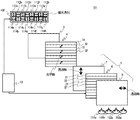
図8に示すように、第3実施形態の立体画像表示装置101の別の構成例で用いられるバックライト172は、水平方向に伸びる、1列の光源173a〜173hの列から構成されている。光源の列は、例えば、白色の無偏光を放射する、8個の光源173a〜173hにより構成される。そして、8個の光源173a〜173hの上にはそれぞれ偏光板174が配置される。例えば、水平方向と垂直な方向に偏光方向を有する偏光板174が配置されて、8個の光源173a〜173hは、水平方向と垂直な方向に直線偏光を放射する偏光光源となる。   As shown in FIG. 8, the backlight 172 used in another configuration example of the stereoscopic image display apparatus 101 according to the third embodiment includes a single row of light sources 173 a to 173 h extending in the horizontal direction. The row of light sources includes, for example, eight light sources 173a to 173h that emit white non-polarized light. A polarizing plate 174 is disposed on each of the eight light sources 173a to 173h. For example, a polarizing plate 174 having a polarization direction in a direction perpendicular to the horizontal direction is disposed, and the eight light sources 173a to 173h are polarization light sources that emit linearly polarized light in a direction perpendicular to the horizontal direction.

8個の光源173a〜173h上の偏光板174の上には、さらに液晶素子175が配置される。液晶素子は、表面にITOなどの透明電極が形成された一対の透明基板によって、90度ツイストのネマティック液晶を挟持して構成された液晶素子である。この液晶素子は、電圧の印加により基板間の液晶の配向変化が可能である。そして、液晶素子175は、電圧無印加時には90度の旋光性を有し、電圧が印加されるとその旋光性は消失する。   A liquid crystal element 175 is further disposed on the polarizing plate 174 on the eight light sources 173a to 173h. The liquid crystal element is a liquid crystal element formed by sandwiching a 90 degree twisted nematic liquid crystal between a pair of transparent substrates on the surface of which transparent electrodes such as ITO are formed. This liquid crystal element can change the alignment of the liquid crystal between the substrates by applying a voltage. The liquid crystal element 175 has an optical rotation of 90 degrees when no voltage is applied, and the optical rotation disappears when a voltage is applied.

したがって、光源173a〜173hと偏光板174と液晶素子175とからなるバックライト172では、液晶素子175への電圧印加の有無により、各光源から放射される光の偏光特性を個別に選択することができる。   Therefore, in the backlight 172 including the light sources 173a to 173h, the polarizing plate 174, and the liquid crystal element 175, the polarization characteristics of the light emitted from each light source can be individually selected depending on whether or not the voltage is applied to the liquid crystal element 175. it can.

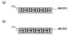
図9は、バックライトから放射される光の偏光特性を模式的に示す図である。図9(a)は、バックライトから放射される光の偏光特性の一例を模式的に示す図であり、図9(b)は、バックライトから放射される光の偏光特性の別の例を模式的に示す図である。   FIG. 9 is a diagram schematically illustrating the polarization characteristics of light emitted from the backlight. FIG. 9A is a diagram schematically illustrating an example of the polarization characteristic of light emitted from the backlight, and FIG. 9B is another example of the polarization characteristic of light emitted from the backlight. It is a figure shown typically.

その結果、図9(a)に示すように、バックライト172において、光源173a、173c、173e、173gと偏光板174と液晶素子175とからは、水平方向と垂直な偏光方向の直線偏光を放射することができ、光源173b、173d、173f、173hと偏光板174と液晶素子175とからは、水平方向と水平な偏光方向の直線偏光を放射することができる。   As a result, as shown in FIG. 9A, in the backlight 172, the light sources 173a, 173c, 173e, 173g, the polarizing plate 174, and the liquid crystal element 175 radiate linearly polarized light having a polarization direction perpendicular to the horizontal direction. The light sources 173b, 173d, 173f, and 173h, the polarizing plate 174, and the liquid crystal element 175 can emit linearly polarized light in the horizontal direction and the horizontal polarization direction.

また、液晶素子を駆動させ、放射される光の偏光状態を切り替えて、図9(b)に示すように、光源173a、173c、173e、173gと偏光板174と液晶素子175とからは、水平方向と水平な偏光方向の直線偏光を放射することができ、光源173b、173d、173f、173hと偏光板174と液晶素子175とからは、水平方向と垂直な偏光方向の直線偏光を放射することができる。   In addition, the liquid crystal element is driven to switch the polarization state of the emitted light, and as shown in FIG. 9B, the light sources 173a, 173c, 173e, 173g, the polarizing plate 174, and the liquid crystal element 175 are Can emit linearly polarized light in the direction parallel to the horizontal direction, and radiate linearly polarized light in the direction perpendicular to the horizontal direction from the light sources 173b, 173d, 173f, 173h, the polarizing plate 174, and the liquid crystal element 175. Can do.

バックライト172は、上記の構成を備えることにより、光源の列において各偏光光源から放射される光の偏向特性を制御することができ、上述の第3実施形態の立体画像表示装置101のバックライト102と同様の機能を水平方向一列の光源の列によって果たすことができる。
したがって、第3実施形態の立体画像表示装置101の別の構成例では、バックライト102の代わりにバックライト172を用い、第3実施形態の立体画像表示装置101と同様に立体画像を形成することができる。
Since the backlight 172 has the above-described configuration, it can control the deflection characteristics of light emitted from each polarized light source in the row of light sources, and the backlight of the stereoscopic image display apparatus 101 of the third embodiment described above. A function similar to 102 can be achieved by a row of light sources in a horizontal direction.
Therefore, in another configuration example of the stereoscopic image display apparatus 101 according to the third embodiment, a backlight 172 is used instead of the backlight 102 and a stereoscopic image is formed in the same manner as the stereoscopic image display apparatus 101 according to the third embodiment. Can do.

尚、第3実施形態の立体画像表示装置101の別の構成例において、バックライト172の光源の列を点灯させる場合、全ての光源173a〜173hを点灯させる必要はない。
例えば、立体画像表示装置に観察者の位置を感知するセンサーを設けておく。そして、観察者が一人である場合、その観察位置(視点)をセンサーによって確認するとともに、視点に対応する光源のみが点灯するよう制御し、液晶素子の制御も行い、一人の観察者の視点に対してのみ最適な立体画像を提供することも可能である。
In another configuration example of the stereoscopic image display apparatus 101 according to the third embodiment, when the light source row of the backlight 172 is turned on, it is not necessary to turn on all the light sources 173a to 173h.
For example, a sensor for sensing the position of the observer is provided in the stereoscopic image display device. When there is only one observer, the observation position (viewpoint) is confirmed by a sensor, and only the light source corresponding to the viewpoint is turned on, the liquid crystal element is also controlled, and the viewpoint of one observer is It is also possible to provide an optimal stereoscopic image only for that.

また、図6に示す第3実施形態の立体画像表示装置101のバックライト102では、上側の第1列において、中央を境にして2つの偏光光源113aと偏光光源113bが左右に配置されて1つの組を構成している。他の偏光光源(113c〜113h)についても、それぞれ、偏光光源113cと偏光光源113dが中央を境にして左右に配置されて1つの組を構成し、偏光光源113eと偏光光源113fが中央を境にして左右に配置されて1つの組を構成し、偏光光源113gと偏光光源113hが中央を境にして左右に配置されて1つの組を構成している。   In the backlight 102 of the stereoscopic image display apparatus 101 according to the third embodiment shown in FIG. 6, two polarized light sources 113a and 113b are arranged on the left and right sides of the center in the first row on the upper side. It constitutes one set. For the other polarized light sources (113c to 113h), the polarized light source 113c and the polarized light source 113d are arranged on the left and right sides of the center to form one set, and the polarized light source 113e and the polarized light source 113f are located at the center. The polarized light source 113g and the polarized light source 113h are arranged on the left and right with the center as a boundary to constitute one set.

それに対し、第3実施形態の立体画像表示装置101の別の構成例においては、対応するように、光源の組を形成する必要はない。例えば、光源173bと光源173cのみを点灯させ、中央を境にして左右に配置された光源の組を構成することも可能である。その場合、具備する液晶素子を制御して、光源173b、173cから出射される光を所望の特性の直線偏光に変換し、立体画像の形成に用いることができる。   On the other hand, in another configuration example of the stereoscopic image display apparatus 101 of the third embodiment, it is not necessary to form a set of light sources so as to correspond. For example, only the light source 173b and the light source 173c may be turned on, and a set of light sources arranged on the left and right with the center as a boundary may be configured. In that case, by controlling the liquid crystal element included, the light emitted from the light sources 173b and 173c can be converted into linearly polarized light with desired characteristics and used for the formation of a stereoscopic image.

その結果、立体画像表示装置に観察者の位置を感知するセンサーを設けておき、観察者が左右方向に移動した際に、その観察位置を確認し、その位置に対応して、光源の列の中から最適な左右画像を観察者に提供可能な二つの隣接する光源を選択することができる。そして、選択された光源の組から放射される直線偏光の特性を制御して、観察者に対し、左右の逆の画像を提供すること無く、最適な左目用画像と右目用画像を提供し、立体画像を観察できるようにすることが可能となる。   As a result, a sensor for detecting the position of the observer is provided in the stereoscopic image display device, and when the observer moves in the left-right direction, the observation position is confirmed, and the column of the light source corresponding to the position is confirmed. It is possible to select two adjacent light sources that can provide the viewer with the optimal left and right images. Then, by controlling the characteristics of the linearly polarized light emitted from the set of selected light sources, the optimal left-eye image and right-eye image are provided to the observer without providing the left and right reverse images, A stereoscopic image can be observed.

また、第3実施形態の立体画像表示装置101のさらに別の構成例として、バックライト102について、偏光光源113a〜113hおよび偏光光源114a〜114hを、それぞれ、上述した第2実施形態の立体画像表示装置61の偏光光源63a等と同様に、円偏光を放射する偏光光源とすることも可能である。その場合、光源の列の、中央を境にして左右に配置される偏光光源の組のそれぞれにおいて、放射する円偏光の偏光方向が、左円偏光および右円偏光と左右逆になるように構成する。   Further, as still another configuration example of the stereoscopic image display apparatus 101 of the third embodiment, the polarized light sources 113a to 113h and the polarized light sources 114a to 114h are respectively used for the backlight 102 in the stereoscopic image display of the second embodiment described above. Similarly to the polarized light source 63a of the device 61, a polarized light source that emits circularly polarized light can be used. In such a case, the polarization direction of the circularly polarized light radiated in each of the pairs of polarized light sources arranged on the left and right sides of the center of the light source row is configured to be opposite to that of the left circularly polarized light and the right circularly polarized light. To do.

また、光源の第1列と第2列との関係についても、上述した第2実施形態の立体画像表示装置61のバックライト62と同様、2つの列の間で上下に隣接する偏光光源の偏光特性は、左円偏光および右円偏光と左右逆になるように構成する。   Further, regarding the relationship between the first column and the second column of the light source, similarly to the backlight 62 of the stereoscopic image display device 61 of the second embodiment described above, the polarization of the polarized light source adjacent vertically between the two columns. The characteristic is configured to be opposite to that of left circularly polarized light and right circularly polarized light.

そして、位相差板には、上述した図5の第2実施形態の立体画像表示装置61の位相差板74と同様、第一偏光領域と第二偏光領域とが、それぞれ光学軸が直交する1/4波長板から構成された位相差板を用いる。こうして、図5に示す立体画像表示装置61と同様、他の構成要素と組み合わせ、第3実施形態の立体画像表示装置101のさらに別の例を構成することが可能である。   As in the retardation plate 74 of the stereoscopic image display device 61 according to the second embodiment shown in FIG. 5 described above, the first polarizing region and the second polarizing region are orthogonal to each other. A retardation plate composed of a / 4 wavelength plate is used. In this manner, in the same manner as the stereoscopic image display device 61 shown in FIG. 5, another example of the stereoscopic image display device 101 of the third embodiment can be configured by combining with other components.

<実施の形態4>
本発明の第4実施形態の立体画像表示装置201は、立体画像の観察に好適な視点(観察位置)が、左右方向に複数配置されるよう構成されるとともに、上下方向の視野角を拡大するよう構成されている。
第4実施形態の立体画像表示装置201は、上下方向の視角を拡大するよう、バックライト202の構成が異なること以外、上述した第3実施形態の立体画像表示装置101と同様の構造を有する。
<Embodiment 4>
The stereoscopic image display apparatus 201 according to the fourth embodiment of the present invention is configured such that a plurality of viewpoints (observation positions) suitable for stereoscopic image observation are arranged in the left-right direction and expands the viewing angle in the vertical direction. It is configured as follows.
The stereoscopic image display apparatus 201 according to the fourth embodiment has the same structure as the stereoscopic image display apparatus 101 according to the third embodiment described above, except that the configuration of the backlight 202 is different so as to enlarge the viewing angle in the vertical direction.

したがって、図面を用いてバックライト202の構造について説明し、その後、立体画像表示装置201の効果について説明する。そして、上述した第1実施形態の立体画像表示装置1および第3実施形態の立体画像表示装置101と共通する構成要素については、共通する符号を用いるようにし、重複する説明を省略する。   Therefore, the structure of the backlight 202 will be described with reference to the drawings, and then the effect of the stereoscopic image display device 201 will be described. And about the component which is common in the stereoscopic image display apparatus 1 of 1st Embodiment mentioned above and the stereoscopic image display apparatus 101 of 3rd Embodiment, a common code | symbol is used and the overlapping description is abbreviate | omitted.

図10は、本発明の第4実施形態の立体画像表示装置の有するバックライトを模式的に説明する平面図である。   FIG. 10 is a plan view schematically illustrating the backlight included in the stereoscopic image display apparatus according to the fourth embodiment of the present invention.

第4実施形態の立体画像表示装置201は、例えば、図10に示されるバックライト202を有する。したがって、上述した第3実施形態の立体画像表示装置101と同様、左右方向の4つ視点(観察位置)に対応するよう構成されている。また、1人の観察者250が、第4実施形態の立体画像表示装置201により立体画像を観察する場合においては、左右に複数の視点があることから、左右の複数の位置から立体画像の観察をすることができ、左右方向に広い視野角が改善された立体画像を観察することが可能となる。   A stereoscopic image display apparatus 201 according to the fourth embodiment includes, for example, a backlight 202 illustrated in FIG. Therefore, similarly to the stereoscopic image display apparatus 101 of the third embodiment described above, it is configured to correspond to four viewpoints (observation positions) in the left-right direction. Further, when one observer 250 observes a stereoscopic image by the stereoscopic image display device 201 of the fourth embodiment, since there are a plurality of viewpoints on the left and right, the stereoscopic image is observed from a plurality of positions on the left and right. It is possible to observe a stereoscopic image with a wide viewing angle improved in the left-right direction.

また、本発明の第4実施形態の立体画像表示装置201では、液晶ディスプレイ5の液晶パネル6の第一画像形成領域21と第二画像形成領域22は、垂直方向に連続して並べられた複数の水平ライン23からそれぞれ構成されている。位相差板4においても、複数の水平ライン23からなる第一画像形成領域21と第二画像形成領域22に対応するよう、第一偏光領域31および第二偏光領域32が設けられている。したがって、画面の上下方向に広い視角を有する。   In the stereoscopic image display device 201 according to the fourth embodiment of the present invention, the first image forming area 21 and the second image forming area 22 of the liquid crystal panel 6 of the liquid crystal display 5 are arranged in a row in the vertical direction. The horizontal lines 23 are respectively configured. Also in the phase difference plate 4, a first polarizing region 31 and a second polarizing region 32 are provided so as to correspond to the first image forming region 21 and the second image forming region 22 formed of a plurality of horizontal lines 23. Therefore, it has a wide viewing angle in the vertical direction of the screen.

したがって、本発明の第4実施形態の立体画像表示装置201では、そうした液晶ディスプレイ5での広い視角を利用して、バックライト202は、偏光光源の列が上下2列より多い数の光源の列を有することが可能である。例えば、図10に示すように上下方向に8列の光源の列を有することが可能である。このように、バックライト202において、多数の偏光光源の列を備えることにより、後述するように、立体画像表示装置201においては、上下方向の視野角を拡大することができる。
尚、上下方向に配置される光源の列は上記例の8列に限られず、4列や6列やそれより多い数とすることも可能である。
Therefore, in the stereoscopic image display apparatus 201 according to the fourth embodiment of the present invention, the backlight 202 uses the wide viewing angle on the liquid crystal display 5 and the backlight 202 includes a plurality of light source columns in which the number of polarized light sources is greater than the upper and lower columns. It is possible to have For example, as shown in FIG. 10, it is possible to have eight rows of light sources in the vertical direction. Thus, by providing the backlight 202 with a large number of rows of polarized light sources, the viewing angle in the vertical direction can be expanded in the stereoscopic image display device 201 as will be described later.
Note that the number of rows of light sources arranged in the vertical direction is not limited to the eight rows in the above example, and may be four rows, six rows, or more.

本発明の第4実施形態の立体画像表示装置201では、図6に示す第3の実施形態の立体画像表示装置101と同様、バックライト202は、観察者から見て立体画像表示装置201の最も奥側に配置される。
そして、本発明の第4実施形態の立体画像表示装置201では、図10に示すように、バックライト202が、それぞれ水平方向に伸びる8つの光源の列から構成されている。具体的には、第1列である光源の列211、第2列である列212、第3列である列213、第4列である列214、第5列である列215、第6列である列216、第7列である列217および第8列である列218の8つ列から構成されている。これら光源の列211〜218の構成は、上述した第3の実施形態である立体画像表示装置101のバックライト102の光源の第1列や第2列と同様である。すなわち、バックライト202の光源の列211〜218は、それぞれ8つの偏光光源から構成されている。
In the stereoscopic image display device 201 according to the fourth embodiment of the present invention, the backlight 202 is the most of the stereoscopic image display device 201 as viewed from the observer, like the stereoscopic image display device 101 according to the third embodiment shown in FIG. Arranged on the back side.
And in the three-dimensional image display apparatus 201 of 4th Embodiment of this invention, as shown in FIG. 10, the backlight 202 is comprised from the row | line | column of eight light sources each extended in a horizontal direction. Specifically, the first light source column 211, the second column 212, the third column 213, the fourth column 214, the fifth column 215, and the sixth column. Column 216, seventh column 217, and eighth column 218. The configurations of these light source columns 211 to 218 are the same as those of the first column and the second column of the light sources of the backlight 102 of the stereoscopic image display apparatus 101 according to the third embodiment described above. That is, each of the light source columns 211 to 218 of the backlight 202 is composed of eight polarized light sources.

そして、バックライト202の光源の列である第1列211、第3列213、第5列215および第7列217は、それぞれ、上述の第3実施形態である立体画像表示装置101のバックライト102の光源の第1列と同様の構造を有する。また、バックライト202の光源の列である第2列212、第4列214、第6列216および第8列218は、それぞれ、上述の第3実施形態である立体画像表示装置101のバックライト102の光源の第2列と同様の構造を有する。   The first column 211, the third column 213, the fifth column 215, and the seventh column 217, which are the light source columns of the backlight 202, are respectively the backlights of the stereoscopic image display apparatus 101 according to the third embodiment. It has the same structure as the first row of 102 light sources. Also, the second column 212, the fourth column 214, the sixth column 216, and the eighth column 218, which are the light source columns of the backlight 202, are respectively the backlights of the stereoscopic image display apparatus 101 according to the third embodiment. It has the same structure as the second row of 102 light sources.

そして、光源の第1列である列211〜第8列である列218を構成する64個の偏光光源は、それぞれ独立に、点灯状態の制御が可能となるようにされている。したがって、バックライト202においては、光源の列211〜218ごとに点灯状態の制御を行うことができる。   The 64 polarized light sources constituting the first row of light sources 211 to 218, which are the first row of light sources, can be controlled independently. Therefore, in the backlight 202, the lighting state can be controlled for each of the light source columns 211 to 218.

以上の構成を有する本発明の第4実施形態の立体画像表示装置201のバックライト202では、上述した第3実施形態の立体画像表示装置101のバックライト102が上下方向に4つ並べられて配置されているのと同様の構成となる。すなわち、バックライト202の光源の第1列である列211と第2列である列212の組が、第3実施形態の立体画像表示装置101のバックライト102と同様に機能する。同様に、バックライト202の光源の第3列である列213と第4列である列214の組、第5列である列215と第6列である列216の組、および第7列である列217と第8列である列218の組が、それぞれ、第3実施形態の立体画像表示装置101のバックライト102と同様に機能する。   In the backlight 202 of the stereoscopic image display apparatus 201 according to the fourth embodiment of the present invention having the above configuration, the four backlights 102 of the stereoscopic image display apparatus 101 according to the third embodiment described above are arranged in the vertical direction. The configuration is the same as that described above. That is, a set of the first column 211 and the second column 212 of the light source of the backlight 202 functions in the same manner as the backlight 102 of the stereoscopic image display apparatus 101 of the third embodiment. Similarly, in the column 213 which is the third column and the column 214 which is the fourth column, the column 215 which is the fifth column and the column 216 which is the sixth column, and the seventh column of the light source of the backlight 202 A set of a certain column 217 and an eighth column 218 functions in the same manner as the backlight 102 of the stereoscopic image display apparatus 101 of the third embodiment.

その場合、バックライト202の光源の第1列である列211、第3列である列213、第5列である列215および第7列である列217が、それぞれ、上述の第3実施形態である立体画像表示装置101のバックライト102の光源の第1列に対応し、同様の機能を果たす。そして、バックライト202の光源の第2列である列212、第4列である列214、第6列である列216および第8列である列218が、それぞれ、上述の第3実施形態である立体画像表示装置101のバックライト102の光源の第2列に対応し、同様の機能を果たす。   In this case, the column 211 as the first column, the column 213 as the third column, the column 215 as the fifth column, and the column 217 as the seventh column of the light source of the backlight 202 are respectively described in the third embodiment. Corresponds to the first column of the light source of the backlight 102 of the stereoscopic image display apparatus 101, and performs the same function. Then, the second column 212, the fourth column 214, the sixth column 216, and the eighth column 218 of the light source of the backlight 202 are respectively in the third embodiment. It corresponds to the second column of the light source of the backlight 102 of a certain stereoscopic image display apparatus 101 and performs the same function.

図11は、本発明の第4実施形態の立体画像表示装置の光学系を模式的に説明する側面図である。
図11に示すように、立体画像表示装置201において、立体画像を観察するのに最適な観察者250の視点の位置は、上下方向については、バックライト202の最上部にある光源の第1列である列211と第2列である列212の組に最適な位置から、最下部にある光源の第7列である列217と第8列である列218の組に最適な位置まで広がることになる。
FIG. 11 is a side view schematically illustrating the optical system of the stereoscopic image display apparatus according to the fourth embodiment of the present invention.
As shown in FIG. 11, in the stereoscopic image display device 201, the viewpoint position of the observer 250 that is optimal for observing a stereoscopic image is the first row of light sources at the top of the backlight 202 in the vertical direction. From the optimal position for the pair of the column 211 and the second column 212 to the optimal position for the group of the second column 217 and the eighth column 218 of the light source at the bottom. become.

すなわち、図11に示す立体画像表示装置201の上下方向に視点については、バックライト202の最上部にある光源の第1列211と第2列212の組に最適な位置と、光源の第3列213と第4列214の組に最適な位置と、光源の第5列215と第6列216の組に最適な位置と、光源の第7列217と第8列218の組に最適な位置とからなる、4つの視点を有する。尚、上述した第3実施形態の立体画像表示装置101のバックライト102においては、光源の列の組は、第1列と第2列からなる一組である。したがって、立体画像表示装置201の上下方向に視角については、第3実施形態の立体画像表示装置101に比べて広がることになる。   That is, regarding the vertical viewpoint of the stereoscopic image display apparatus 201 shown in FIG. 11, the optimal position for the set of the first row 211 and the second row 212 of the light source at the top of the backlight 202, and the third light source Optimal position for the set of column 213 and fourth column 214, Optimal position for the set of fifth column 215 and sixth column 216 of light source, and Optimal for the set of seventh column 217 and eighth column 218 of light source It has four viewpoints consisting of position. In the backlight 102 of the stereoscopic image display apparatus 101 according to the third embodiment described above, the set of light source columns is a set of a first column and a second column. Therefore, the viewing angle in the vertical direction of the stereoscopic image display device 201 is wider than that of the stereoscopic image display device 101 of the third embodiment.

以上より、第4実施形態の立体画像表示装置201は、左右方向の視覚拡大に加え、上下方向の視角拡大も可能であり、多様な方向から立体画像を観察できるという効果を有する。   As described above, the stereoscopic image display apparatus 201 according to the fourth embodiment can increase the viewing angle in the vertical direction in addition to the visual expansion in the left-right direction, and has an effect that a stereoscopic image can be observed from various directions.

尚、第4実施形態の立体画像表示装置201において、バックライト202の光源の第1列である列211、第3列である列213、第5列である列215および第7列である列217を点灯させる場合、全ての列を同時に点灯させる必要はない。同様に、光源の第2列である列212、第4列である列214、第6列である列216および第8列である列218を点灯させる場合、全ての光源の列を点灯させる必要はない。
例えば、立体画像表示装置201に観察者の位置を感知するセンサーを設けておく。そして、観察者が一人である場合、その観察位置(視点)をセンサーによって確認するとともに、視点に対応する偏光光源のみが点灯するよう制御し、一人の観察者の視点に対してのみ最適な立体画像を提供することも可能である。
In the stereoscopic image display apparatus 201 according to the fourth embodiment, the column 211 that is the first column of the light source of the backlight 202, the column 213 that is the third column, the column 215 that is the fifth column, and the column that is the seventh column. When 217 is lit, it is not necessary to light all the columns simultaneously. Similarly, when the column 212, which is the second column of light sources, the column 214, which is the fourth column, the column 216, which is the sixth column, and the column 218, which is the eighth column, are lit, all the columns of the light sources need to be lit. There is no.
For example, the stereoscopic image display device 201 is provided with a sensor that detects the position of the observer. When there is only one observer, the observation position (viewpoint) is confirmed by a sensor, and only the polarized light source corresponding to the viewpoint is controlled to be turned on. It is also possible to provide an image.

また、第4実施形態の立体画像表示装置201の別の構成例として、バックライト202の各偏光光源を、上述した第2実施形態の立体画像表示装置61の偏光光源63a等と同様に、円偏光を放射する偏光光源とすることも可能である。その場合、8列の光源のそれぞれにおいて、中央を境にして左右に配置される偏光光源の各組を、放射する円偏光の偏光方向が、左円偏光および右円偏光と左右逆になるように構成する。   Further, as another configuration example of the stereoscopic image display device 201 of the fourth embodiment, each polarization light source of the backlight 202 is a circle like the polarization light source 63a of the stereoscopic image display device 61 of the second embodiment described above. A polarized light source that emits polarized light may be used. In that case, in each of the eight rows of light sources, the polarization direction of the circularly polarized light emitted from each pair of the polarized light sources arranged on the left and right with the center as the boundary is opposite to that of the left circularly polarized light and the right circularly polarized light. Configure.

光源の上下に隣接する列同士の関係についても、上述した第2実施形態の立体画像表示装置61のバックライト62と同様とし、2つの列の間で上下に隣接する偏光光源の偏光特性は、左円偏光および右円偏光と左右逆になるように構成する。   The relationship between the columns adjacent to the upper and lower sides of the light source is the same as the backlight 62 of the stereoscopic image display device 61 of the second embodiment described above, and the polarization characteristics of the polarized light source adjacent to the upper and lower sides between the two columns are as follows. The left and right circularly polarized lights are configured to be opposite to the left and right circularly polarized lights.

そして、位相差板には、上述した図5の第2実施形態の立体画像表示装置61の位相差板74と同様、第一偏光領域と第二偏光領域とが、それぞれ光学軸が直交する1/4波長板から構成された位相差板を用いる。こうして、図5に示す立体画像表示装置61と同様、他の構成要素と組み合わせ、第4実施形態の立体画像表示装置201のさらに別の例を構成することが可能である。   As in the retardation plate 74 of the stereoscopic image display device 61 according to the second embodiment shown in FIG. 5 described above, the first polarizing region and the second polarizing region are orthogonal to each other. A retardation plate composed of a / 4 wavelength plate is used. In this manner, in the same manner as the stereoscopic image display device 61 shown in FIG. 5, it is possible to configure still another example of the stereoscopic image display device 201 of the fourth embodiment by combining with other components.

尚、本発明は、上記実施の形態に限定されるものではなく、本発明の趣旨を逸脱しない範囲内において、種々変形して実施することができる。   The present invention is not limited to the above-described embodiment, and various modifications can be made without departing from the spirit of the present invention.

1、61、101,201 立体画像表示装置
2、62、102、172、202 バックライト
3 フレネルレンズ
4、74 位相差板
5 液晶ディスプレイ
6 液晶パネル
7、8、17a、17b、18a、18b、174 偏光板
12 制御装置
13a、13b、14a、14b、63a、63b、64a、64b、113a、113b、113c、113d、113e、113f、113g、113h、114a、114b、114c、114d、114e、114f、114g、114h 偏光光源
15a、15b、173a、173b、173c、173d、173e、173f、173g、173h 光源
21 第一画像形成領域
22 第二画像形成領域
23 水平ライン
31、71 第一偏光領域
32、72 第二偏光領域
41a、81a、141a、141c、141e、141g 右目
41b、81b、141b、141d、141f、141h 左目
50、80、150a、150b、150c、150d、250 観察者
175 液晶素子
211、212、213、214、215、216、217、218 光源の列
1, 61, 101, 201 Stereoscopic image display device 2, 62, 102, 172, 202 Backlight 3 Fresnel lens 4, 74 Phase difference plate 5 Liquid crystal display 6 Liquid crystal panel 7, 8, 17a, 17b, 18a, 18b, 174 Polarizer 12 Controller 13a, 13b, 14a, 14b, 63a, 63b, 64a, 64b, 113a, 113b, 113c, 113d, 113e, 113f, 113g, 113h, 114a, 114b, 114c, 114d, 114e, 114f, 114g , 114h Polarized light source 15a, 15b, 173a, 173b, 173c, 173d, 173e, 173f, 173g, 173h Light source 21 First image forming area 22 Second image forming area 23 Horizontal line 31, 71 First polarizing area 32, 72 First Two polarization regions 41a, 8 a, 141a, 141c, 141e, 141g Right eye 41b, 81b, 141b, 141d, 141f, 141h Left eye 50, 80, 150a, 150b, 150c, 150d, 250 Observer 175 Liquid crystal element 211, 212, 213, 214, 215, 216, 217, 218 Row of light sources

Claims (13)

画素を水平方向に配列してなる水平ラインを垂直方向に複数並べて構成された液晶パネルおよび前記液晶パネルを挟持する一対の偏光板を有する液晶ディスプレイと、
偏光を放射する複数の偏光光源を、左右に隣接する前記偏光光源の間で放射光の偏光方向が互いに異なるよう、水平方向に配列してなる偏光光源の列を備えたバックライトとを有し、
前記液晶ディスプレイと前記バックライトとの間に集光レンズと光学手段とをこの順で配置し、
観察者に立体画像を提供する立体画像表示装置であって、
前記バックライトは、前記偏光光源の列を垂直方向に複数列配置するとともに、垂直方向に隣接する前記偏光光源の列の間では、垂直方向に隣接する前記偏光光源間で放射光の偏光方向が互いに異なるように構成されており、
前記集光レンズは、前記バックライトからの光を前記観察者に向けて集光する光にするよう構成されたものであり、
前記液晶ディスプレイは、前記液晶パネルの連設された複数の前記水平ラインからなる第一画像形成領域と第二画像形成領域とを交互に配置して有し、前記第一画像形成領域は右目用画像および左目用画像のいずれか一方の画像を、前記第二画像形成領域は他方の画像をそれぞれ同時に表示するよう構成され、
前記第一画像形成領域と前記第二画像形成領域は、
(1)フレーム切り替え毎に右目用画像と左目用画像の入れ替えを行うか、
または、
(2)(1)以外の場合であって、フレームの切り替え時に右目用画像と左目用画像の入れ替えおよび直前のフレームで表示された画像の上書きのいずれか一方を行うよう構成されており、
前記光学手段は、前記第一画像形成領域と前記第二画像形成領域とに対応する位置と大きさで、第一偏光領域と第二偏光領域とが配置され、前記第一偏光領域と前記第二偏光領域とは、いずれか一方が1/2波長板を形成するか、両方が遅相軸が互い45度異なる1/2波長板を形成するか、または両方が遅相軸が互い90度異なる1/4波長板を形成するによう構成されたものであることを特徴とする立体画像表示装置。
A liquid crystal display having a pair of polarizing plates sandwiching the liquid crystal panel, and a liquid crystal panel configured by arranging a plurality of horizontal lines in the vertical direction by arranging pixels in the horizontal direction;
A plurality of polarized light sources that emit polarized light, and a backlight having a row of polarized light sources arranged in a horizontal direction so that the polarization directions of the emitted light are different between the polarized light sources adjacent to the left and right ,
A condensing lens and optical means are arranged in this order between the liquid crystal display and the backlight,
A stereoscopic image display device that provides a stereoscopic image to an observer,
The backlight includes a plurality of columns of the polarized light sources arranged in the vertical direction, and the polarization direction of the emitted light is between the polarized light sources adjacent in the vertical direction between the columns of the polarized light sources adjacent in the vertical direction. Configured to be different from each other,
The condensing lens is configured to collect light from the backlight toward the observer.
The liquid crystal display has a first image forming area and a second image forming area formed by alternately arranging the plurality of horizontal lines of the liquid crystal panel, and the first image forming area is for the right eye. One of the image and the image for the left eye, and the second image forming area is configured to simultaneously display the other image,
The first image forming area and the second image forming area are:
(1) Whether the image for the right eye and the image for the left eye are switched every time the frame is switched,
Or
(2) In cases other than (1), when switching frames, the right-eye image and the left-eye image are interchanged and the image displayed in the previous frame is overwritten.
The optical means includes a first polarizing region and a second polarizing region at positions and sizes corresponding to the first image forming region and the second image forming region, and the first polarizing region and the first polarizing region. Either one of the two polarization regions forms a half-wave plate, or both form half-wave plates whose slow axes are 45 degrees different from each other, or both have the slow axes of 90 degrees each other. A three-dimensional image display device, which is configured to form different quarter-wave plates.
前記バックライトは、前記偏光光源の列毎に点灯制御されるよう構成されたことを特徴とする請求項1に記載の立体画像表示装置。   The stereoscopic image display device according to claim 1, wherein the backlight is configured to be controlled to be lit for each column of the polarized light sources. 前記バックライトは、前記偏光光源毎に点灯制御されるよう構成されたことを特徴とする請求項1に記載の立体画像表示装置。   The stereoscopic image display device according to claim 1, wherein the backlight is configured to be controlled to be turned on for each polarized light source. 前記バックライトの前記偏光光源の列は、4つ以上の前記偏光光源からなることを特徴とする請求項1〜3のいずれか1項に記載の立体画像表示装置。   The stereoscopic image display device according to claim 1, wherein the row of the polarized light sources of the backlight includes four or more polarized light sources. 前記バックライトは、前記偏光光源の列を、上下方向に4列以上配置して構成されたものであることを特徴とする請求項1〜4のいずれか1項に記載の立体画像表示装置。   5. The stereoscopic image display device according to claim 1, wherein the backlight is configured by arranging four or more rows of the polarized light sources in the vertical direction. 前記バックライトは、前記右目用画像と前記左目用画像を入れ替えるタイミングに合わせて、全体の点灯状態が制御されるよう構成されたものであることを特徴とする請求項1〜5のいずれか1項に記載の立体画像表示装置。   The said backlight is comprised so that the whole lighting state may be controlled according to the timing which replaces the said image for right eyes, and the said image for left eyes, The any one of Claims 1-5 characterized by the above-mentioned. The stereoscopic image display device according to item. 前記バックライトの前記偏光光源は、LEDと偏光板とを用いて構成されたものであることを特徴とする請求項1〜6のいずれか1項に記載の立体画像表示装置。   The stereoscopic image display apparatus according to claim 1, wherein the polarized light source of the backlight is configured using an LED and a polarizing plate. 前記光学手段の前記第一偏光領域と第二偏光領域との境界の少なくとも一部には、遮光部が設けられていることを特徴とする請求項1〜7のいずれか1項に記載の立体画像表示装置。   The three-dimensional object according to any one of claims 1 to 7, wherein a light-shielding portion is provided at least at a part of a boundary between the first polarizing region and the second polarizing region of the optical means. Image display device. 前記第一画像形成領域と前記第二画像形成領域とはそれぞれ、前記液晶パネルの垂直方向に連続して並べられた2本から60本の水平ラインからなる画像形成領域であることを特徴とする請求項1〜8のいずれか1項に記載の立体画像表示装置。   Each of the first image forming area and the second image forming area is an image forming area composed of 2 to 60 horizontal lines arranged continuously in the vertical direction of the liquid crystal panel. The three-dimensional image display apparatus of any one of Claims 1-8. 前記第一画像形成領域と前記第二画像形成領域とはそれぞれ、前記液晶パネルの垂直方向に連続して並べられた3本から30本の水平ラインからなる画像形成領域であることを特徴とする請求項9に記載の立体画像表示装置。   Each of the first image forming area and the second image forming area is an image forming area composed of 3 to 30 horizontal lines arranged continuously in the vertical direction of the liquid crystal panel. The stereoscopic image display apparatus according to claim 9. 前記第一画像形成領域と前記第二画像形成領域とはそれぞれ、前記液晶パネルの垂直方向に連続して並べられた5本から15本の水平ラインからなる画像形成領域であることを特徴とする請求項9に記載の立体画像表示装置。   Each of the first image forming area and the second image forming area is an image forming area composed of 5 to 15 horizontal lines arranged continuously in the vertical direction of the liquid crystal panel. The stereoscopic image display apparatus according to claim 9. 前記液晶ディスプレイにおけるフレームの切り替えは、120Hz以上の周期で行われることを特徴とする請求項1〜11のいずれか1項に記載の立体画像表示装置。   The stereoscopic image display device according to any one of claims 1 to 11, wherein the frame switching in the liquid crystal display is performed at a cycle of 120 Hz or more. 前記液晶ディスプレイにおけるフレームの切り替えは、240Hz以上の周期で行われることを特徴とする請求項12に記載の立体画像表示装置。   The stereoscopic image display device according to claim 12, wherein the frame switching in the liquid crystal display is performed at a cycle of 240 Hz or more.
JP2011066159A 2011-03-24 2011-03-24 Stereoscopic image display device Pending JP2012203111A (en)

Priority Applications (1)

Application Number Priority Date Filing Date Title
JP2011066159A JP2012203111A (en) 2011-03-24 2011-03-24 Stereoscopic image display device

Applications Claiming Priority (1)

Application Number Priority Date Filing Date Title
JP2011066159A JP2012203111A (en) 2011-03-24 2011-03-24 Stereoscopic image display device

Publications (1)

Publication Number Publication Date
JP2012203111A true JP2012203111A (en) 2012-10-22

Family

ID=47184213

Family Applications (1)

Application Number Title Priority Date Filing Date
JP2011066159A Pending JP2012203111A (en) 2011-03-24 2011-03-24 Stereoscopic image display device

Country Status (1)

Country Link
JP (1) JP2012203111A (en)

Cited By (2)

* Cited by examiner, † Cited by third party
Publication number Priority date Publication date Assignee Title
JP2023002592A (en) * 2017-12-27 2023-01-10 日亜化学工業株式会社 light emitting device
CN115903261A (en) * 2022-07-26 2023-04-04 华为技术有限公司 An image generation device, display device, vehicle and image generation method

Citations (8)

* Cited by examiner, † Cited by third party
Publication number Priority date Publication date Assignee Title
JP2004264363A (en) * 2003-02-19 2004-09-24 Sophia Co Ltd Image display apparatus
WO2005012980A1 (en) * 2003-07-30 2005-02-10 Seijiro Tomita 3-dimensional video display device
WO2005079078A1 (en) * 2004-02-17 2005-08-25 Seijiro Tomita Stereoscopic video image recording/reproducing method and stereoscopic video image display
JP2005292722A (en) * 2004-04-05 2005-10-20 Arisawa Mfg Co Ltd Stereoscopic image display device
JP2006081388A (en) * 2004-09-06 2006-03-23 Taida Electronic Ind Co Ltd Forced heat dissipation structure of motor
JP2006284873A (en) * 2005-03-31 2006-10-19 Arisawa Mfg Co Ltd Image display device
JP2008245068A (en) * 2007-03-28 2008-10-09 Nanao Corp Stereoscopic image pickup and display system, and stereoscopic image display device
JP2009139593A (en) * 2007-12-05 2009-06-25 Arisawa Mfg Co Ltd Stereoscopic image display device and phase difference plate

Patent Citations (8)

* Cited by examiner, † Cited by third party
Publication number Priority date Publication date Assignee Title
JP2004264363A (en) * 2003-02-19 2004-09-24 Sophia Co Ltd Image display apparatus
WO2005012980A1 (en) * 2003-07-30 2005-02-10 Seijiro Tomita 3-dimensional video display device
WO2005079078A1 (en) * 2004-02-17 2005-08-25 Seijiro Tomita Stereoscopic video image recording/reproducing method and stereoscopic video image display
JP2005292722A (en) * 2004-04-05 2005-10-20 Arisawa Mfg Co Ltd Stereoscopic image display device
JP2006081388A (en) * 2004-09-06 2006-03-23 Taida Electronic Ind Co Ltd Forced heat dissipation structure of motor
JP2006284873A (en) * 2005-03-31 2006-10-19 Arisawa Mfg Co Ltd Image display device
JP2008245068A (en) * 2007-03-28 2008-10-09 Nanao Corp Stereoscopic image pickup and display system, and stereoscopic image display device
JP2009139593A (en) * 2007-12-05 2009-06-25 Arisawa Mfg Co Ltd Stereoscopic image display device and phase difference plate

Cited By (3)

* Cited by examiner, † Cited by third party
Publication number Priority date Publication date Assignee Title
JP2023002592A (en) * 2017-12-27 2023-01-10 日亜化学工業株式会社 light emitting device
JP7389383B2 (en) 2017-12-27 2023-11-30 日亜化学工業株式会社 light emitting device
CN115903261A (en) * 2022-07-26 2023-04-04 华为技术有限公司 An image generation device, display device, vehicle and image generation method

Similar Documents

Publication Publication Date Title
JP5033264B2 (en) Stereoscopic image display apparatus and stereoscopic image display method
JP5603042B2 (en) Stereoscopic image display device
JP5156606B2 (en) Stereoscopic image display device
EP2062444B1 (en) Multi-view autostereoscopic display with improved resolution
CN101782687B (en) Display device for displaying three-dimensional images
JP5420665B2 (en) Stereoscopic image display device
JP5285160B2 (en) Stereoscopic image display device
US7986283B2 (en) Multi-dimensional image selectable display device
US9052537B1 (en) 2D/3D image switching type liquid crystal display
JP5852124B2 (en) Stereoscopic display system, glasses used in the system, and display method therefor
CN101825773A (en) Display device
JPWO2012096032A1 (en) Stereoscopic image display device
US20130050284A1 (en) Display device and electronic unit
JP5297996B2 (en) Stereoscopic image display apparatus and stereoscopic image display method
TWI474048B (en) Display device
JP2012203111A (en) Stereoscopic image display device
JP5539746B2 (en) Stereoscopic image display device
US9224230B2 (en) Method of displaying three-dimensional image and display apparatus for performing the same
JP2010079216A (en) Stereoscopic image display
TWI420150B (en) Stereoscopic image display
JP2012123129A (en) Stereoscopic image display device
CN103217802A (en) Liquid crystal display panel and device thereof
JP2007304236A (en) Liquid crystal display
KR20130034552A (en) 3 dimensional stereography image displayable system

Legal Events

Date Code Title Description
A621 Written request for application examination

Free format text: JAPANESE INTERMEDIATE CODE: A621

Effective date: 20130920

A977 Report on retrieval

Free format text: JAPANESE INTERMEDIATE CODE: A971007

Effective date: 20140212

A131 Notification of reasons for refusal

Free format text: JAPANESE INTERMEDIATE CODE: A131

Effective date: 20140218

A02 Decision of refusal

Free format text: JAPANESE INTERMEDIATE CODE: A02

Effective date: 20140624