JP2012204319A - Thermally actuated switch, fixing device and image forming apparatus - Google Patents

Thermally actuated switch, fixing device and image forming apparatus Download PDF

Info

Publication number
JP2012204319A
JP2012204319A JP2011070887A JP2011070887A JP2012204319A JP 2012204319 A JP2012204319 A JP 2012204319A JP 2011070887 A JP2011070887 A JP 2011070887A JP 2011070887 A JP2011070887 A JP 2011070887A JP 2012204319 A JP2012204319 A JP 2012204319A
Authority
JP
Japan
Prior art keywords
electrode
contact
housing
bimetal
displacement member
Prior art date
Legal status (The legal status is an assumption and is not a legal conclusion. Google has not performed a legal analysis and makes no representation as to the accuracy of the status listed.)
Withdrawn
Application number
JP2011070887A
Other languages
Japanese (ja)
Inventor
Tomohiro Masumura
朋洋 増村
Katsuya Saito
克哉 齋藤
Atsushi Hiroi
敦之 廣井
Toshihiko Mihashi
利彦 三橋
Current Assignee (The listed assignees may be inaccurate. Google has not performed a legal analysis and makes no representation or warranty as to the accuracy of the list.)
Fujifilm Business Innovation Corp
Original Assignee
Fuji Xerox Co Ltd
Priority date (The priority date is an assumption and is not a legal conclusion. Google has not performed a legal analysis and makes no representation as to the accuracy of the date listed.)
Filing date
Publication date
Application filed by Fuji Xerox Co Ltd filed Critical Fuji Xerox Co Ltd
Priority to JP2011070887A priority Critical patent/JP2012204319A/en
Priority to US13/267,349 priority patent/US8626006B2/en
Priority to CN2011103500161A priority patent/CN102709110A/en
Publication of JP2012204319A publication Critical patent/JP2012204319A/en
Withdrawn legal-status Critical Current

Links

Images

Classifications

    • GPHYSICS
    • G03PHOTOGRAPHY; CINEMATOGRAPHY; ANALOGOUS TECHNIQUES USING WAVES OTHER THAN OPTICAL WAVES; ELECTROGRAPHY; HOLOGRAPHY
    • G03GELECTROGRAPHY; ELECTROPHOTOGRAPHY; MAGNETOGRAPHY
    • G03G15/00Apparatus for electrographic processes using a charge pattern
    • G03G15/20Apparatus for electrographic processes using a charge pattern for fixing, e.g. by using heat
    • G03G15/2003Apparatus for electrographic processes using a charge pattern for fixing, e.g. by using heat using heat
    • G03G15/2014Apparatus for electrographic processes using a charge pattern for fixing, e.g. by using heat using heat using contact heat
    • G03G15/2017Structural details of the fixing unit in general, e.g. cooling means, heat shielding means
    • GPHYSICS
    • G03PHOTOGRAPHY; CINEMATOGRAPHY; ANALOGOUS TECHNIQUES USING WAVES OTHER THAN OPTICAL WAVES; ELECTROGRAPHY; HOLOGRAPHY
    • G03GELECTROGRAPHY; ELECTROPHOTOGRAPHY; MAGNETOGRAPHY
    • G03G21/00Arrangements not provided for by groups G03G13/00 - G03G19/00, e.g. cleaning, elimination of residual charge
    • G03G21/16Mechanical means for facilitating the maintenance of the apparatus, e.g. modular arrangements
    • G03G21/1642Mechanical means for facilitating the maintenance of the apparatus, e.g. modular arrangements for connecting the different parts of the apparatus
    • G03G21/1652Electrical connection means
    • HELECTRICITY
    • H01ELECTRIC ELEMENTS
    • H01HELECTRIC SWITCHES; RELAYS; SELECTORS; EMERGENCY PROTECTIVE DEVICES
    • H01H37/00Thermally-actuated switches
    • H01H37/02Details
    • H01H37/32Thermally-sensitive members
    • H01H37/52Thermally-sensitive members actuated due to deflection of bimetallic element
    • H01H37/54Thermally-sensitive members actuated due to deflection of bimetallic element wherein the bimetallic element is inherently snap acting
    • H01H37/5409Bistable switches; Resetting means
    • HELECTRICITY
    • H01ELECTRIC ELEMENTS
    • H01HELECTRIC SWITCHES; RELAYS; SELECTORS; EMERGENCY PROTECTIVE DEVICES
    • H01H37/00Thermally-actuated switches
    • H01H37/02Details
    • H01H37/32Thermally-sensitive members
    • H01H37/52Thermally-sensitive members actuated due to deflection of bimetallic element
    • H01H37/54Thermally-sensitive members actuated due to deflection of bimetallic element wherein the bimetallic element is inherently snap acting
    • H01H2037/549Details of movement transmission between bimetallic snap element and contact

Landscapes

  • Physics & Mathematics (AREA)
  • General Physics & Mathematics (AREA)
  • Thermal Sciences (AREA)
  • Thermally Actuated Switches (AREA)
  • Fixing For Electrophotography (AREA)

Abstract

PROBLEM TO BE SOLVED: To provide a thermally actuated switch which has a simple structure and prevents contacts from being brought into contact with each other while a push member recovered by pushing a displacement member is being pushed.SOLUTION: The thermally actuated switch comprises a push member which is provided and extended from a gap between a displacement member and a second electrode to a first electrode, by being pushed one edge because of a convex displacement of the displacement member, pushes the electrode, separates a first contact from a second contact and has the other edge extending to outside of a housing. The push member also pushes the displacement member to recover to the concave state because the other edge is pushed from the outside of the housing to the displacement member side, and maintains a separating condition between the first contact and the second contact because the second electrode is pushed and elastically deformed.

Description

本発明は、熱応動スイッチ、定着装置及び画像形成装置に関する。   The present invention relates to a thermally responsive switch, a fixing device, and an image forming apparatus.

特許文献1には、バイメタル15のスナップ動作によって接続端子10,11間の内部接続が遮断され、リセット軸9の挿入によって内部接続が復旧する手動復帰型サーモスタットTH1であって、バイメタル15のスナップ動作またはリセット軸9の挿入動作に応答して移動する可動接点3,4と、可動接点3,4に対面して固定配置される固定接点1a,2aとからなる開閉接点を2組備えて、バイメタル15がスナップ動作した場合には、開閉接点1a,3が開離される一方、リセット軸9が挿入された場合には開閉接点2a,4が開離され、リセット軸9が挿入されている限りその状態を維持するようになっている構成が開示されている。   Patent Document 1 discloses a manual reset thermostat TH1 in which the internal connection between the connection terminals 10 and 11 is interrupted by the snap operation of the bimetal 15 and the internal connection is restored by the insertion of the reset shaft 9, and the snap operation of the bimetal 15 Alternatively, two sets of open / close contacts including movable contacts 3 and 4 that move in response to the insertion operation of the reset shaft 9 and fixed contacts 1a and 2a that are fixedly disposed facing the movable contacts 3 and 4 are provided. When 15 is snapped, the switching contacts 1a and 3 are separated, while when the reset shaft 9 is inserted, the switching contacts 2a and 4 are separated and the reset shaft 9 is inserted. A configuration is disclosed that is adapted to maintain the state.

特許文献2には、以下の構成が開示されている。固定接点2は、ベース1に固定されている。板バネ4は、基端部がベース1に保持され、先端部に可動接点3が設けられ、可動接点3を固定接点2へ付勢する。可動操作材5は、ベース1に揺動可能に軸受され、基端部5bが押下げられることで先端部が押上げられる。可動操作材5の先端部の押上げは、可動接点3を固定接点2から上方へ離間させる。ガイドピン6は、可動操作材5の基端側上部に上下動可能に配置され、バイメタル7の反転動作に基づき可動操作材5の基端部を押下げる。可動操作材5の下部に設置されたリセット軸8を上方へ押し込むと、可動接点3を押上げると共に、ガイドピン6を押上げてバイメタル7を復帰可能である。   Patent Document 2 discloses the following configuration. The fixed contact 2 is fixed to the base 1. The leaf spring 4 has a base end portion held by the base 1, a movable contact 3 provided at the distal end, and biases the movable contact 3 toward the fixed contact 2. The movable operation member 5 is supported by the base 1 so as to be swingable, and the distal end portion is pushed up by pushing down the base end portion 5b. Pushing up the tip of the movable operation member 5 moves the movable contact 3 upward from the fixed contact 2. The guide pin 6 is disposed on the upper part of the base end side of the movable operation member 5 so as to be movable up and down, and pushes down the base end portion of the movable operation member 5 based on the reversing operation of the bimetal 7. When the reset shaft 8 installed at the lower part of the movable operation member 5 is pushed upward, the movable contact 3 is pushed up, and the guide pin 6 is pushed up to return the bimetal 7.

特開平9−198980号公報JP-A-9-198980 特開2005−353390号公報JP 2005-353390 A

本発明は、簡易な構成で、変位部材を押すことで復帰させる押し部材が押されたままの状態では、接点同士が接触しないようにすることを課題とする。   An object of the present invention is to prevent the contacts from coming into contact with each other in a state where the push member to be returned by pushing the displacement member is kept pressed with a simple configuration.

請求項1の発明は、筐体と、前記筐体の内部に対して凹状に前記筐体に保持され、温度変化に応じて前記筐体の内部に対して凸状に変位する変位部材と、前記筐体の内部に設けられた第1接点を有する第1電極と、前記変位部材と前記第1電極との間に設けられた第2接点を有し、前記第1接点が前記変位部材側へ付勢された状態で前記第1接点に対して前記第2接点が接触する第2電極と、前記変位部材と前記第2電極との間から前記第1電極へ延び設けられ、前記変位部材の凸状の変位により端部が押されることで前記第1電極を押して前記第1接点を前記第2接点から離す第1押し部材と、前記変位部材が変位した状態で端部が筐体外部へ突出し、該端部が筐体外部から前記変位部材側へ押されることで前記変位部材を押して凹状に復帰させると共に前記第2電極を押して弾性変形させて前記第1接点を前記第2接点との離間状態を維持する第2押し部材と、を備える熱応動スイッチである。   The invention of claim 1 is a housing and a displacement member that is held in the housing in a concave shape with respect to the inside of the housing, and that is displaced in a convex shape with respect to the inside of the housing in response to a temperature change, A first electrode having a first contact provided in the housing; and a second contact provided between the displacement member and the first electrode, wherein the first contact is on the displacement member side. A second electrode contacting the first contact with the first contact in a state of being biased toward the first electrode, and extending from between the displacement member and the second electrode to the first electrode, the displacement member A first pressing member that pushes the first electrode by pushing the end portion by the convex displacement of the first and separates the first contact from the second contact, and the end portion is outside the housing in a state where the displacement member is displaced. And the end is pushed to the displacement member side from the outside of the housing, so that the displacement member is pushed into the concave shape. A thermo-switch comprising: a second press member, the maintaining the separated state between the second press electrode elastically deformed so the first contact with the second contact with is.

請求項2の発明は、前記第1押し部材と前記第2押し部材が一体となっていることを特徴とする熱応動スイッチである。   According to a second aspect of the present invention, there is provided a thermally responsive switch in which the first push member and the second push member are integrated.

請求項3は、前記第1押し部材は、前記第1電極と前記変位部材との間に設けられ、前記第1電極側端部に形成され前記変位部材の凸状の変位により前記変位部材側端部が押されることで前記第1電極を押す第1面と、前記第1面よりも前記変位部材側に第2電極側を向いて形成された第2面を有し、前記第2押し部材は、前記第1押し部材の前記第1電極側端部から前記変位部材側とは反対側に向かって前記筐体外へ延び設けられ、筐体外部から前記変位部材側へ押されることで前記第2電極を押して前記第1接点を前記第2接点との離間状態を維持し、さらに前記第2電極を介して前記第2面を押すことで前記変位部材を押して凹状に復帰させる請求項1に記載の熱応動スイッチである。   According to a third aspect of the present invention, the first pressing member is provided between the first electrode and the displacement member, and is formed at the first electrode side end portion, and the displacement member side is formed by the convex displacement of the displacement member. A first surface that pushes the first electrode by pressing an end portion; and a second surface that is formed on the side of the second electrode closer to the displacement member than the first surface. The member extends from the first electrode side end of the first push member toward the opposite side to the displacement member side and is provided outside the case, and is pushed to the displacement member side from the outside of the case. 2. The second electrode is pushed to maintain the first contact with the second contact, and the second member is pushed through the second electrode to push the displacement member to return to a concave shape. It is a thermally responsive switch as described in.

請求項4の発明は、記録媒体上の画像を加熱する加熱部材と、前記加熱部材へ給電するための回路と、前記第1電極及び第2電極が前記回路内に設けられ、前記変位部材が前記加熱部材から受ける放射熱による温度変化に応じて変位して前記第1接点と前記第2接点とが離れることで前記回路を遮断する請求項1〜3のいずれか1項に記載の熱応動スイッチと、を備える、前記画像を前記記録媒体に定着させる定着装置である。   According to a fourth aspect of the present invention, a heating member for heating an image on a recording medium, a circuit for supplying power to the heating member, the first electrode and the second electrode are provided in the circuit, and the displacement member is The thermal response according to any one of claims 1 to 3, wherein the circuit is interrupted by being displaced according to a temperature change caused by radiant heat received from the heating member and separating the first contact and the second contact. A fixing device that fixes the image on the recording medium.

請求項5の発明は、画像を記録媒体に形成する画像形成部と、前記画像形成部で形成された画像を記録媒体へ定着させる請求項4に記載の定着装置と、を備える画像形成装置である。   According to a fifth aspect of the present invention, there is provided an image forming apparatus comprising: an image forming unit that forms an image on a recording medium; and the fixing device according to the fourth aspect that fixes the image formed by the image forming unit to the recording medium. is there.

本発明の請求項1の構成によれば、本構成に係る第1押し部材及び第2押し部材を備えない構成に比べ、簡易な構成で、変位部材を押すことで復帰させる押し部材が押されたままの状態では、接点同士が接触しないようにできる。   According to the configuration of the first aspect of the present invention, the pressing member to be returned by pressing the displacement member is pushed with a simple configuration as compared with the configuration not including the first pressing member and the second pressing member according to the present configuration. In the state where it is left, it is possible to prevent the contacts from contacting each other.

本発明の請求項2の構成によれば、本構成を備えない構成に比べ、簡易な構成で、変位部材を押すことで復帰させる押し部材が押されたままの状態では、より効果的に、接点同士が接触しないようにできる。   According to the configuration of claim 2 of the present invention, in a state where the pushing member to be returned by pushing the displacement member is pressed with a simple configuration as compared with the configuration without the present configuration, more effectively, The contacts can be prevented from contacting each other.

本発明の請求項3の構成によれば、本構成に係る第1押し部材及び第2押し部材を備えない構成に比べ、簡易な構成で、変位部材を押すことで復帰させる押し部材が押されたままの状態では、より効果的に、接点同士が接触しないようにできる。   According to the configuration of the third aspect of the present invention, the pressing member to be returned by pressing the displacement member is pushed with a simple configuration as compared with the configuration not including the first pressing member and the second pressing member according to the present configuration. In the state as it is, it is possible to prevent the contacts from contacting each other more effectively.

本発明の請求項4の構成によれば、本構成に係る熱応動スイッチを備えない構成に比べ、簡易な構成で、変位部材を押すことで復帰させる押し部材が押されたままの状態において、加熱部材による加熱が禁止される状態が維持できる。   According to the configuration of claim 4 of the present invention, in a state where the push member to be returned by pressing the displacement member is pressed with a simple configuration as compared with the configuration not including the heat responsive switch according to the present configuration, A state where heating by the heating member is prohibited can be maintained.

本発明の請求項5の構成によれば、本構成に係る定着装置を備えない構成に比べ、簡易な構成で、変位部材を押すことで復帰させる押し部材が押されたままの状態において、定着装置による定着が禁止される状態が維持できる。   According to the configuration of the fifth aspect of the present invention, in a state where the pushing member to be returned by pushing the displacement member is pressed with a simple configuration as compared with the configuration not including the fixing device according to the present configuration, the fixing is performed. The state where fixing by the apparatus is prohibited can be maintained.

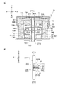
本実施形態に係る画像形成装置の構成を示す概略図である。1 is a schematic diagram illustrating a configuration of an image forming apparatus according to an exemplary embodiment. 本実施形態に係る定着装置の構成を示す断面図である。FIG. 2 is a cross-sectional view illustrating a configuration of a fixing device according to the present embodiment. 本実施形態に係るサーモスタットの外観を示す外観図である。It is an external view which shows the external appearance of the thermostat which concerns on this embodiment. 図3における4−4線断面図であり、(A)は、加熱ロール(定着装置の筐体内部)の温度が、予め定められた温度(通常動作温度)の範囲内である場合のサーモスタットを示し、(B)は加熱ロール(定着装置の筐体内部)の温度が予め定められた温度(通常動作温度)を超えた場合のサーモスタットを示す。4A is a cross-sectional view taken along line 4-4 in FIG. 3, and (A) shows a thermostat when the temperature of the heating roll (inside the casing of the fixing device) is within a predetermined temperature range (normal operating temperature). (B) shows the thermostat when the temperature of the heating roll (inside the casing of the fixing device) exceeds a predetermined temperature (normal operating temperature). ピン、リセット軸、第1電極及び第2電極の構成を示す概略斜視図である。It is a schematic perspective view which shows the structure of a pin, a reset axis | shaft, a 1st electrode, and a 2nd electrode. 図3における4−4線断面図であり、(A)バイメタルの復帰を開始した状態を示し、(B)バイメタルを復帰させた後にピンを押したままにした状態を示す。FIG. 4 is a cross-sectional view taken along line 4-4 in FIG. 3, showing (A) a state in which the return of the bimetal is started, and (B) a state in which the pin is kept pressed after the bimetal is returned. 第1変形例に係るサーモスタットの構成を示す概略図である。It is the schematic which shows the structure of the thermostat which concerns on a 1st modification. 第1変形例に係る押し部材、第1電極及び第2電極の構成を示す概略斜視図である。It is a schematic perspective view which shows the structure of the pushing member which concerns on a 1st modification, a 1st electrode, and a 2nd electrode. 第2変形例に係るサーモスタットの構成を示す概略図である。It is the schematic which shows the structure of the thermostat which concerns on a 2nd modification. 第2変形例に係るサーモスタットの構成において、挿入孔に替えて挿入溝を形成した概略図である。In the structure of the thermostat which concerns on a 2nd modification, it is the schematic which replaced with the insertion hole and formed the insertion groove | channel.

以下に、本発明に係る実施形態の一例を図面に基づき説明する。
(本実施形態に係る画像形成装置の構成)
まず、本実施形態に係る画像形成装置の構成を説明する。図1は、本実施形態に係る画像形成装置の構成を示す概略図である。なお、図中に示す矢印UPは、鉛直方向上方を示している。
Below, an example of an embodiment concerning the present invention is described based on a drawing.
(Configuration of image forming apparatus according to the present embodiment)
First, the configuration of the image forming apparatus according to the present embodiment will be described. FIG. 1 is a schematic diagram illustrating a configuration of an image forming apparatus according to the present embodiment. Note that an arrow UP shown in the drawing indicates a vertically upward direction.

画像形成装置10は、図1に示すように、各構成部品が内部に収容される画像形成装置本体11を備えている。画像形成装置本体11の内部には、用紙等の記録媒体Pが収容される収容部12と、記録媒体Pに画像を形成する画像形成部14と、収容部12から画像形成部14へ記録媒体Pを搬送する搬送部16と、画像形成装置10の各部の動作を制御する制御部20と、画像形成装置10の各部に給電する給電部21と、が設けられている。また、画像形成装置本体11の上部には、画像形成部14によって画像が形成された記録媒体Pが排出される排出部18が設けられている。   As shown in FIG. 1, the image forming apparatus 10 includes an image forming apparatus main body 11 in which each component is housed. Inside the image forming apparatus main body 11, a storage unit 12 that stores a recording medium P such as paper, an image forming unit 14 that forms an image on the recording medium P, and a recording medium from the storage unit 12 to the image forming unit 14. A conveyance unit 16 that conveys P, a control unit 20 that controls the operation of each unit of the image forming apparatus 10, and a power supply unit 21 that supplies power to each unit of the image forming apparatus 10 are provided. In addition, a discharge unit 18 for discharging the recording medium P on which an image is formed by the image forming unit 14 is provided on the upper portion of the image forming apparatus main body 11.

画像形成部14は、イエロー(Y)、マゼンタ(M)、シアン(C)、ブラック(K)の各色のトナー画像を形成する画像形成ユニット22Y、22M、22C、22K(以下、22Y〜22Kと示す)と、画像形成ユニット22Y〜22Kで形成されたトナー画像が転写される中間転写ベルト24と、画像形成ユニット22Y〜22Kで形成されたトナー画像を中間転写ベルト24に転写する第1転写ロール26と、第1転写ロール26によって中間転写ベルト24に転写されたトナー画像を中間転写ベルト24から記録媒体Pへ転写する第2転写ロール28と、を備えている。なお、画像形成部14は、上記の構成に限られず、他の構成であっても良く、記録媒体Pに画像を形成するものであればよい。   The image forming unit 14 includes image forming units 22Y, 22M, 22C, and 22K (hereinafter referred to as 22Y to 22K) that form toner images of colors of yellow (Y), magenta (M), cyan (C), and black (K). And an intermediate transfer belt 24 to which the toner images formed by the image forming units 22Y to 22K are transferred, and a first transfer roll for transferring the toner images formed by the image forming units 22Y to 22K to the intermediate transfer belt 24 26 and a second transfer roll 28 that transfers the toner image transferred to the intermediate transfer belt 24 by the first transfer roll 26 from the intermediate transfer belt 24 to the recording medium P. The image forming unit 14 is not limited to the above-described configuration, and may be another configuration as long as it forms an image on the recording medium P.

画像形成ユニット22Y〜22Kは、水平方向に対して傾斜した状態で、画像形成装置10の上下方向中央部に並んで配置されている。また、画像形成ユニット22Y〜22Kは、一方向(例えば、図1における時計回り方向)へ回転する感光体32をそれぞれ有している。なお、画像形成ユニット22Y〜22Kは、同様に構成されているので、図1において、画像形成ユニット22M、22C、22Kの各部の符号を省略している。   The image forming units 22 </ b> Y to 22 </ b> K are arranged side by side at the center in the vertical direction of the image forming apparatus 10 while being inclined with respect to the horizontal direction. Each of the image forming units 22Y to 22K includes a photoreceptor 32 that rotates in one direction (for example, the clockwise direction in FIG. 1). Since the image forming units 22Y to 22K are configured in the same manner, the reference numerals of the respective parts of the image forming units 22M, 22C, and 22K are omitted in FIG.

各感光体32の周囲には、感光体32の回転方向上流側から順に、感光体32を帯電させる帯電装置の一例としての帯電ロール23と、帯電ロール23によって帯電した感光体32を露光して感光体32に静電潜像を形成する露光装置36と、露光装置36によって感光体32に形成された静電潜像を現像してトナー画像を形成する現像装置38と、感光体32に接触して感光体32に残留しているトナーを除去する除去部材40と、が設けられている。   Around each photoconductor 32, a charging roll 23 as an example of a charging device that charges the photoconductor 32 and a photoconductor 32 charged by the charge roll 23 are exposed in order from the upstream side in the rotation direction of the photoconductor 32. The exposure device 36 that forms an electrostatic latent image on the photoconductor 32, the developing device 38 that develops the electrostatic latent image formed on the photoconductor 32 by the exposure device 36 to form a toner image, and the photoconductor 32. And a removing member 40 for removing the toner remaining on the photosensitive member 32.

露光装置36は、制御部20から送られた画像信号に基づき静電潜像を形成するようになっている。制御部20から送られる画像信号としては、例えば、制御部20が外部装置から取得した画像信号がある。   The exposure device 36 is configured to form an electrostatic latent image based on the image signal sent from the control unit 20. Examples of the image signal sent from the control unit 20 include an image signal acquired by the control unit 20 from an external device.

現像装置38は、感光体32へ現像剤を供給する現像剤供給体38Aと、現像剤供給体38Aへ付与される現像剤を攪拌しながら搬送する複数の搬送部材38Bと、を備えている。   The developing device 38 includes a developer supply body 38A that supplies the developer to the photoconductor 32, and a plurality of transport members 38B that transport the developer applied to the developer supply body 38A while stirring.

中間転写ベルト24は、環状に形成されると共に、画像形成ユニット22Y〜22Kの上側に配置されている。中間転写ベルト24の内周側には、中間転写ベルト24が巻き掛けられる巻掛ロール42・44が設けられている。中間転写ベルト24は、巻掛ロール42・44のいずれかが回転駆動することによって、感光体32と接触しながら一方向(例えば、図1における反時計回り方向)へ循環移動(回転)するようになっている。なお、巻掛ロール42は、第2転写ロール28に対向する対向ロールとされている。   The intermediate transfer belt 24 is formed in an annular shape and is disposed on the upper side of the image forming units 22Y to 22K. On the inner peripheral side of the intermediate transfer belt 24, winding rolls 42 and 44 around which the intermediate transfer belt 24 is wound are provided. The intermediate transfer belt 24 is circulated and moved (rotated) in one direction (for example, counterclockwise in FIG. 1) while being in contact with the photosensitive member 32 by rotating one of the winding rolls 42 and 44. It has become. The winding roll 42 is an opposing roll that faces the second transfer roll 28.

第1転写ロール26は、中間転写ベルト24を挟んで感光体32に対向している。第1転写ロール26と感光体32との間が、感光体32に形成されたトナー画像が中間転写ベルト24に転写される第1転写位置とされている。   The first transfer roll 26 faces the photoconductor 32 with the intermediate transfer belt 24 interposed therebetween. A space between the first transfer roll 26 and the photoconductor 32 is a first transfer position where the toner image formed on the photoconductor 32 is transferred to the intermediate transfer belt 24.

第2転写ロール28は、中間転写ベルト24を挟んで巻掛ロール42に対向している。第2転写ロール28と巻掛ロール42との間が、中間転写ベルト24に転写されたトナー画像が記録媒体Pに転写される第2転写位置とされている。   The second transfer roll 28 faces the winding roll 42 with the intermediate transfer belt 24 interposed therebetween. A space between the second transfer roll 28 and the winding roll 42 is a second transfer position where the toner image transferred to the intermediate transfer belt 24 is transferred to the recording medium P.

搬送部16は、収容部12に収容された記録媒体Pを送り出す送出ロール46と、送出ロール46に送り出された記録媒体Pが搬送される搬送路48と、搬送路48に沿って配置され送出ロール46によって送り出された記録媒体Pを第2転写位置へ搬送する複数の搬送ロール50と、が設けられている。   The transport unit 16 is disposed along the transport path 48 and is transported along a transport roll 48 for transporting the recording medium P stored in the storage section 12, a transport path 48 for transporting the recording medium P transported to the transport roll 46. A plurality of transport rolls 50 are provided for transporting the recording medium P delivered by the roll 46 to the second transfer position.

第2転写位置より搬送方向下流側には、画像形成部14によって記録媒体Pに形成されたトナー画像を記録媒体Pに定着させる定着装置60が設けられている。この定着装置60より搬送方向下流側には、トナー画像が定着された記録媒体Pを排出部18へ排出する排出ロール52が設けられている。なお、定着装置60の具体的な構成については後述する。   A fixing device 60 that fixes the toner image formed on the recording medium P by the image forming unit 14 to the recording medium P is provided on the downstream side in the transport direction from the second transfer position. A discharge roll 52 that discharges the recording medium P on which the toner image is fixed to the discharge unit 18 is provided downstream of the fixing device 60 in the transport direction. A specific configuration of the fixing device 60 will be described later.

次に、本実施形態に係る画像形成装置10における、記録媒体Pへ画像を形成する画像形成動作について説明する。   Next, an image forming operation for forming an image on the recording medium P in the image forming apparatus 10 according to the present embodiment will be described.

本実施形態に係る画像形成装置10では、収容部12から送出ロール46によって送り出された記録媒体Pが、複数の搬送ロール50によって第2転写位置へ送り込まれる。   In the image forming apparatus 10 according to the present embodiment, the recording medium P sent out from the storage unit 12 by the sending roll 46 is sent to the second transfer position by the plurality of conveying rolls 50.

一方、画像形成ユニット22Y〜22Kでは、帯電ロール23によって帯電した感光体32が、露光装置36によって露光されて感光体32に静電潜像が形成される。その静電潜像が現像装置38によって現像されて感光体32にトナー画像が形成される。画像形成ユニット22Y〜22Kで形成された各色のトナー画像は、第1転写位置にて中間転写ベルト24に重ねられて、カラー画像が形成される。そして、中間転写ベルト24に形成されたカラー画像が、第2転写位置にて記録媒体Pへ転写される。   On the other hand, in the image forming units 22 </ b> Y to 22 </ b> K, the photosensitive member 32 charged by the charging roll 23 is exposed by the exposure device 36 to form an electrostatic latent image on the photosensitive member 32. The electrostatic latent image is developed by the developing device 38 to form a toner image on the photoreceptor 32. The color toner images formed by the image forming units 22Y to 22K are superimposed on the intermediate transfer belt 24 at the first transfer position to form a color image. Then, the color image formed on the intermediate transfer belt 24 is transferred to the recording medium P at the second transfer position.

トナー画像が転写された記録媒体Pは、定着装置60へ搬送され、転写されたトナー画像が定着装置60により定着される。トナー画像が定着された記録媒体Pは、排出ロール52によって排出部18に排出される。以上のように、一連の画像形成動作が行われる。   The recording medium P to which the toner image has been transferred is conveyed to the fixing device 60, and the transferred toner image is fixed by the fixing device 60. The recording medium P on which the toner image is fixed is discharged to the discharge unit 18 by the discharge roll 52. As described above, a series of image forming operations are performed.

(本実施形態に係る定着装置60の構成)
次に、本実施形態に係る定着装置60の構成を説明する。図2は、本実施形態に係る定着装置60の構成を示す概略図である。なお、図中に示す矢印UPは、鉛直方向上方を示している。
(Configuration of the fixing device 60 according to the present embodiment)
Next, the configuration of the fixing device 60 according to the present embodiment will be described. FIG. 2 is a schematic diagram illustrating a configuration of the fixing device 60 according to the present embodiment. Note that an arrow UP shown in the drawing indicates a vertically upward direction.

本実施形態に係る定着装置60は、図2に示すように、画像形成装置本体11(図1参照)に対して着脱可能に設けられ、各構成部品が内部に設けられる筐体62を備えている。筐体62の内部には、記録媒体上の画像を加熱する加熱部材の一例としての加熱ロール64と、加圧部材の一例としての加圧ベルト66と、が設けられている。   As shown in FIG. 2, the fixing device 60 according to the present embodiment is provided so as to be detachable from the image forming apparatus main body 11 (see FIG. 1), and includes a housing 62 in which each component is provided. Yes. Inside the housing 62 are provided a heating roll 64 as an example of a heating member for heating an image on a recording medium, and a pressure belt 66 as an example of a pressure member.

加熱ロール64は、円筒状の円筒部材64Aと、円筒部材64Aの内部空間に設けられたハロゲンランプ等の加熱源64Bと、を備えて構成されている。円筒部材64Aは、アルミニウム・ステンレス等の金属材料により形成されている。   The heating roll 64 includes a cylindrical cylindrical member 64A and a heating source 64B such as a halogen lamp provided in the internal space of the cylindrical member 64A. The cylindrical member 64A is formed of a metal material such as aluminum or stainless steel.

加熱源64Bは、加熱ロール64(加熱源64B)へ給電するための回路の一例としての電気回路25によって、給電部21と電気的に接続されている。これにより、加熱源64Bは、給電部21から電気回路25を通じて給電されるように構成されている。   The heating source 64B is electrically connected to the power feeding unit 21 by an electric circuit 25 as an example of a circuit for feeding power to the heating roll 64 (heating source 64B). As a result, the heating source 64B is configured to be supplied with power from the power supply unit 21 through the electric circuit 25.

加圧ベルト66は、加熱ロール64との間に記録媒体Pを挟んで回転し、該記録媒体Pを加圧しながら搬送する環状の搬送ベルトとして構成されている。   The pressure belt 66 is configured as an annular conveyance belt that rotates while sandwiching the recording medium P with the heating roll 64 and conveys the recording medium P while applying pressure.

加熱ロール64及び加圧ベルト66によって挟まれて搬送される記録媒体Pは、加熱ロール64によってトナーが加熱されると共に加圧ベルト66によってトナーが加圧されて、加熱ロール64と加圧ベルト66との接触領域において画像が定着されるようになっている。なお、図2においては、加熱ロール64・加圧ベルト66によって、記録媒体Pが搬送される搬送経路が二点鎖線で示されている。   The recording medium P sandwiched and transported between the heating roll 64 and the pressure belt 66 is heated with the toner by the heating roll 64 and pressurized with the pressure belt 66, and the heating roll 64 and the pressure belt 66. The image is fixed in the contact area. In FIG. 2, the conveyance path along which the recording medium P is conveyed by the heating roll 64 and the pressure belt 66 is indicated by a two-dot chain line.

定着装置60の筐体62には、熱応動スイッチの一例としてのサーモスタット70が設けられている。具体的には、サーモスタット70は、後述のバイメタル76(図3参照)を加熱ロール64側に向けて、加熱ロール64に対して予め定められた隙間をあけて、定着装置60の筐体62に設けられている。サーモスタット70は、図1に示すように、電気回路25内に設けられており、加熱ロール64(筐体62内部)の温度が予め定められた温度になった場合に電気回路25を遮断し、給電部21から加熱源64Bへの給電を停止するように構成されている。   The casing 62 of the fixing device 60 is provided with a thermostat 70 as an example of a thermally responsive switch. Specifically, the thermostat 70 has a bimetal 76 (see FIG. 3), which will be described later, directed toward the heating roll 64 and a predetermined gap with respect to the heating roll 64, and is provided in the casing 62 of the fixing device 60. Is provided. As shown in FIG. 1, the thermostat 70 is provided in the electric circuit 25, and shuts off the electric circuit 25 when the temperature of the heating roll 64 (inside the housing 62) reaches a predetermined temperature. It is comprised so that the electric power feeding from the electric power feeding part 21 to the heat source 64B may be stopped.

(本実施形態に係るサーモスタット70の具体的な構成)
次に、本実施形態に係るサーモスタット70の具体的な構成を説明する。図3〜5は、サーモスタット70の構成を示す概略図である。なお、下記のX方向・−X方向・Y方向・−Y方向・Z方向は、図中に示す矢印方向である。また、図中の「○」の中に「×」が記載されたものは、手前から奥へ向かう矢印を意味する。
(Specific configuration of thermostat 70 according to the present embodiment)
Next, a specific configuration of the thermostat 70 according to the present embodiment will be described. 3 to 5 are schematic views showing the configuration of the thermostat 70. FIG. The following X direction, −X direction, Y direction, −Y direction, and Z direction are the arrow directions shown in the figure. Moreover, what is indicated by “x” in “◯” in the figure means an arrow heading from the front to the back.

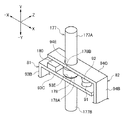
本実施形態に係るサーモスタット70は、図2及び図3に示すように、定着装置60の筐体62に形成された挿入孔62Aに挿入される装置本体71を備えている。装置本体71は、挿入孔62Aに挿入されることにより、定着装置60の筐体62に取り付けられる。   As shown in FIGS. 2 and 3, the thermostat 70 according to the present embodiment includes a device main body 71 that is inserted into an insertion hole 62 </ b> A formed in the housing 62 of the fixing device 60. The apparatus main body 71 is attached to the casing 62 of the fixing device 60 by being inserted into the insertion hole 62A.

サーモスタット70の装置本体71は、図3及び図4に示すように、一端部(Y方向側端部)が開放された開放部72Aを有する円筒状の筐体72と、筐体72の開放部72Aに設けられた筐体72の軸方向(Y方向)へ後述のピン78を案内するピンガイド80と、筐体72に設けられた保持部材の一例としてのキャップ74と、筐体72に設けられた第1電極81及び第2電極82と、を備えている。   As shown in FIGS. 3 and 4, the apparatus main body 71 of the thermostat 70 includes a cylindrical casing 72 having an opening 72 </ b> A whose one end (Y-direction side end) is open, and an opening of the casing 72. A pin guide 80 for guiding a pin 78 (described later) in the axial direction (Y direction) of the housing 72 provided in 72 A, a cap 74 as an example of a holding member provided in the housing 72, and a housing 72. The first electrode 81 and the second electrode 82 are provided.

筐体72の底壁72Cには、図4に示すように、筐体72の平面視(−Y方向矢視)における中央部(中心部)において筐体72の軸方向(Y方向)へ貫通し、後述のピン78が挿入される挿入孔72Dが、形成されている。筐体72は、絶縁性を有する材料で構成されている。絶縁性を有する材料としては、例えば、セラミック、フェノール樹脂、ポリフェニレンスルフィルド等が用いられる。なお、筐体72の形状、材料は、上記に限られるものではない。   As shown in FIG. 4, the bottom wall 72 </ b> C of the housing 72 penetrates in the axial direction (Y direction) of the housing 72 at the center (center portion) of the housing 72 in plan view (as viewed in the −Y direction). An insertion hole 72D into which a pin 78 described later is inserted is formed. The casing 72 is made of an insulating material. As the material having insulating properties, for example, ceramic, phenol resin, polyphenylene sulfide, or the like is used. Note that the shape and material of the housing 72 are not limited to the above.

ピンガイド80は、筐体72の軸方向(Y方向)へ貫通しピン78が挿入される挿入孔80Aを内部に有する円板状に形成されている。ピンガイド80は、筐体72の平面視(−Y方向矢視)における中央側において筐体72の底壁72C側(−Y方向側)へ突出する凸部80Bが、筐体72の開放部72Aに差し込まれると共に、外周部が、筐体72の開放端部(Y方向側端部)とキャップ74との間に挟まれるように保持されている。ピンガイド80では、ピン78がピンガイド80に挿入された状態において、ピン78がピンガイド80の挿入孔80Aに沿って筐体72の軸方向(Y方向)への移動が許容されると共に、ピンガイド80の内壁に当ることで筐体72の径方向(−X方向・X方向)への移動が規制されるようになっている。   The pin guide 80 is formed in a disk shape that has an insertion hole 80 </ b> A that penetrates in the axial direction (Y direction) of the housing 72 and into which the pin 78 is inserted. The pin guide 80 has a convex portion 80 </ b> B that protrudes toward the bottom wall 72 </ b> C side (−Y direction side) of the housing 72 at the center side in a plan view (as viewed in the −Y direction) of the housing 72. The outer peripheral part is held so as to be sandwiched between the open end part (Y direction side end part) of the housing 72 and the cap 74 while being inserted into 72A. In the pin guide 80, in the state where the pin 78 is inserted into the pin guide 80, the pin 78 is allowed to move in the axial direction (Y direction) of the housing 72 along the insertion hole 80A of the pin guide 80, and By hitting the inner wall of the pin guide 80, the movement of the casing 72 in the radial direction (−X direction / X direction) is restricted.

ピンガイド80とキャップ74との間には、温度変化に応じて変位する変位部材の一例としてのバイメタル76が設けられている。バイメタル76は、皿バネ状に形成(絞り形成)されており、キャップ74とピンガイド80とによって、筐体72の内部に対して凹状(図4(A)に示す状態)に筐体72に保持されている。また、バイメタル76は、線膨張率の異なる2種類の金属を接合することによって構成されており、予め定められた温度になると、筐体72の内部に対して凸状(図4(B)に示す状態)に変位(反転)するようにされている。   A bimetal 76 is provided between the pin guide 80 and the cap 74 as an example of a displacement member that is displaced according to a temperature change. The bimetal 76 is formed in the shape of a disc spring (drawing formation), and the cap 72 and the pin guide 80 form a concave shape (in the state shown in FIG. 4A) with respect to the inside of the housing 72. Is retained. The bimetal 76 is formed by joining two kinds of metals having different linear expansion coefficients. When the temperature reaches a predetermined temperature, the bimetal 76 has a convex shape (see FIG. 4B). (State shown) is displaced (inverted).

キャップ74の平面視(−Y方向矢視)における中央部には、図3に示すように、バイメタル76の表面を外部に露出される円形状の開口部74Aが形成されている。キャップ74は、筐体72に対してカシメられることにより、筐体72に対して固定されている。   As shown in FIG. 3, a circular opening 74 </ b> A that exposes the surface of the bimetal 76 to the outside is formed at the center of the cap 74 in a plan view (as viewed in the −Y direction arrow). The cap 74 is fixed to the casing 72 by being caulked with respect to the casing 72.

第1電極81は、図4に示すように、筐体72内部に設けられ側面視(Z方向矢視)にてコの字状の可動電極93と、筐体72の底壁72Cの外面に設けられた端子95と、筐体72の底壁72Cを貫通し端子95と可動電極93とを電気的に接続するリベット97と、を備えて構成されている。   As shown in FIG. 4, the first electrode 81 is provided inside the casing 72 and is formed on the outer surface of the U-shaped movable electrode 93 and the bottom wall 72 </ b> C of the casing 72 when viewed from the side (Z direction arrow). The terminal 95 is provided, and a rivet 97 that penetrates the bottom wall 72C of the housing 72 and electrically connects the terminal 95 and the movable electrode 93 is provided.

可動電極93は、耐熱性、導電性及び弾性(ばね性)を有する板状電極をコの字状に屈曲することで構成されている。可動電極93は、筐体72の底壁72Cの内面に設けられた第1部93Aと、筐体72の側壁72Bの内面側に設けられ第1部93Aの側壁72B側(−X方向側)端部からバイメタル76側(Y方向)へ延びる第2部93Bと、第2部93Bのバイメタル76側(Y方向側)端部から筐体72の径方向(X方向)へ延びる第3部93Cと、を備えている。   The movable electrode 93 is configured by bending a plate electrode having heat resistance, conductivity, and elasticity (spring property) into a U-shape. The movable electrode 93 is provided on the inner surface side of the side wall 72B of the housing 72 and the first portion 93A provided on the inner surface of the bottom wall 72C of the housing 72, and on the side wall 72B side (−X direction side) of the first portion 93A. A second portion 93B extending from the end portion to the bimetal 76 side (Y direction), and a third portion 93C extending from the end portion of the second portion 93B to the bimetal 76 side (Y direction side) in the radial direction (X direction) of the housing 72. And.

可動電極93は、第1部93Aでリベット97と電気的に接続される。可動電極93の第3部93Cは、筐体72の径方向(X方向)に長さを有し、長手方向中間部が筐体72の平面視(−Y方向矢視)における中央部を通っている。この長手方向中間部には、バイメタル76側に突出し後述のピン78の第1面781と接触する接触部93Dが形成されている。また、この長手方向中間部には、可動電極93の厚み方向へ貫通し後述のリセット軸79が挿入される挿入孔93Eが形成されている。さらに、第3部93Cの先端部(X方向側端部)には、バイメタル76側に突出し後述の第2接点92と接触する第1接点91が形成されている。   The movable electrode 93 is electrically connected to the rivet 97 at the first portion 93A. The third portion 93 </ b> C of the movable electrode 93 has a length in the radial direction (X direction) of the housing 72, and an intermediate portion in the longitudinal direction passes through a central portion in a plan view of the housing 72 (as viewed in the −Y direction). ing. A contact portion 93D that protrudes toward the bimetal 76 and contacts a first surface 781 of a pin 78 (described later) is formed at the middle portion in the longitudinal direction. Further, an insertion hole 93E that penetrates in the thickness direction of the movable electrode 93 and into which a reset shaft 79 described later is inserted is formed in the middle portion in the longitudinal direction. Furthermore, a first contact 91 that protrudes toward the bimetal 76 and contacts a second contact 92 described later is formed at the tip end (X direction side end) of the third portion 93C.

可動電極93は、後述の第2接点92との接触状態で第1接点91がバイメタル76側(Y方向)へ付勢されている。具体的には、可動電極93は、板バネで構成されており、自らの弾性力により、第1接点91がバイメタル76側(Y方向)へ付勢されている。   In the movable electrode 93, the first contact 91 is biased toward the bimetal 76 (Y direction) in a contact state with a second contact 92 described later. Specifically, the movable electrode 93 is configured by a leaf spring, and the first contact 91 is urged toward the bimetal 76 side (Y direction) by its own elastic force.

第2電極82は、図4に示すように、筐体72内部に設けられた側面視(Z方向矢視)にて可動電極93とは逆向きのコの字状とされた可動電極94と、筐体72の径方向中央に対する端子95側とは反対側(X方向側)において筐体72の底壁72Cの外面に設けられた端子96と、筐体72の径方向中央に対するリベット97側とは反対側(X方向側)において筐体72の底壁72Cを貫通し端子96と可動電極94とを電気的に接続するリベット98と、を備えて構成されている。   As shown in FIG. 4, the second electrode 82 includes a movable electrode 94 having a U-shape opposite to the movable electrode 93 in a side view (as viewed in the Z direction) provided inside the housing 72. The terminal 96 provided on the outer surface of the bottom wall 72C of the casing 72 on the opposite side (X direction side) to the radial center of the casing 72 and the rivet 97 side with respect to the radial center of the casing 72 And a rivet 98 that penetrates the bottom wall 72C of the housing 72 and electrically connects the terminal 96 and the movable electrode 94 on the opposite side (X direction side).

可動電極94は、耐熱性、導電性及び弾性(ばね性)を有する板状電極をコの字状に屈曲することで構成されている。可動電極94は、筐体72の底壁72Cの内面に設けられた第1部94Aと、筐体72の側壁72Bの内面側に設けられ第1部94Aの側壁72B側(X方向側)端部から可動電極93の第3部93Cよりもバイメタル76側(Y方向側)へ延びる第2部94Bと、第2部94Bのバイメタル76側(Y方向側)端部から筐体72の径方向(−X方向)へ延びる第3部94Cと、を備えている。   The movable electrode 94 is configured by bending a plate electrode having heat resistance, conductivity and elasticity (spring property) into a U-shape. The movable electrode 94 is provided on the inner surface side of the side wall 72B of the housing 72 and the first portion 94A provided on the inner surface of the bottom wall 72C of the housing 72, and the side wall 72B side (X direction side) end of the first portion 94A. The second portion 94B extending from the portion to the bimetal 76 side (Y direction side) than the third portion 93C of the movable electrode 93, and the radial direction of the housing 72 from the end portion of the second portion 94B on the bimetal 76 side (Y direction side) A third portion 94C extending in the (−X direction).

可動電極94は、第1部94Aでリベット98と電気的に接続される。可動電極94の第3部94Cは、筐体72の径方向(−X方向)に長さを有している。第3部94Cの先端部(−X方向側端部)は、後述のピン78の切欠部78B内に配置されている。第3部94Cの長手方向中間部には、第1電極81側(−Y方向)に突出する第2接点92が形成されている。   The movable electrode 94 is electrically connected to the rivet 98 at the first portion 94A. The third portion 94 </ b> C of the movable electrode 94 has a length in the radial direction (−X direction) of the housing 72. The distal end portion (−X direction side end portion) of the third portion 94C is disposed in a notch portion 78B of the pin 78 described later. A second contact 92 that protrudes toward the first electrode 81 (−Y direction) is formed at the longitudinal intermediate portion of the third portion 94C.

第2接点92は、第1接点91(−Y方向)へ向けられており、第1接点91がバイメタル76側へ付勢された状態で第1接点91に対して接触するようになっている。従って、付勢力に対抗して第1接点91が第2接点92から離れる側(−Y方向)への対抗力が、第1電極81に作用することで、第1接点91が第2接点92と離れ、その対抗力が作用しないことで、第1接点91が第2接点92と接触するようになっている。   The second contact 92 is directed to the first contact 91 (−Y direction), and comes into contact with the first contact 91 in a state where the first contact 91 is biased toward the bimetal 76 side. . Accordingly, the first contact 91 acts on the first electrode 81 due to the opposing force acting on the side where the first contact 91 separates from the second contact 92 (the −Y direction) against the urging force. The first contact 91 comes into contact with the second contact 92 because the opposing force does not act.

なお、耐熱性、導電性及び弾性(ばね性)を有する可動電極93及び可動電極94を構成する部材(電極)としては、例えば、ステンレス、銅、リン青銅等からなる部材、又はこれらの部材をスズ、ニッケル、銀若しくは金等でめっきした部材が用いられる。   In addition, as a member (electrode) which comprises the movable electrode 93 which has heat resistance, electroconductivity, and elasticity (spring property) and the movable electrode 94, the member which consists of stainless steel, copper, phosphor bronze, etc., or these members, for example A member plated with tin, nickel, silver or gold is used.

さらに、サーモスタット70は、バイメタル76と第2電極82との間から第1電極81へ延び設けられた押し部材77を備えている。押し部材77は、第1電極81とバイメタル76との間に設けられた第1押し部材部材の一例としてのピン78と、ピン78の第1電極81側端部(−Y方向側端部)からバイメタル76とは反対側(−Y方向)に向かって筐体72外へ延び設けられた第2押し部材の一例としてのリセット軸79と、を備えている。   Further, the thermostat 70 includes a pressing member 77 provided to extend from between the bimetal 76 and the second electrode 82 to the first electrode 81. The pressing member 77 includes a pin 78 as an example of a first pressing member member provided between the first electrode 81 and the bimetal 76, and an end portion on the first electrode 81 side (an end portion on the −Y direction side) of the pin 78. And a reset shaft 79 as an example of a second pressing member provided to extend out of the housing 72 toward the opposite side (-Y direction) from the bimetal 76.

ピン78は、筐体72の軸方向(Y方向)へ長さを有しており、棒状(例えば、円柱状)に形成されている。また、ピン78は、筐体72の平面視(−Y方向矢視)における中央部(中心部)において筐体72の軸方向(−Y方向)へ移動可能に、ピンガイド80の挿入孔80Aに挿入されている。   The pin 78 has a length in the axial direction (Y direction) of the housing 72 and is formed in a rod shape (for example, a columnar shape). Further, the pin 78 can be moved in the axial direction (−Y direction) of the housing 72 at the central portion (center portion) of the housing 72 in a plan view (as viewed in the −Y direction arrow). Has been inserted.

ピン78の第1電極81側端部(−Y方向側端部)の一部には、図5及び図4に示すように、切欠部78Bが形成されている。これにより、ピン78には、その第1電極81側端部(−Y方向側端部)に第1電極81の接触部93D側(−Y方向)を向く第1面781が形成され、第1面781よりもバイメタル76側(Y方向)に第2電極82の第3部94C側(−Y方向)を向く第2面782が形成されている。   As shown in FIGS. 5 and 4, a notch 78 </ b> B is formed at a part of the first electrode 81 side end (−Y direction side end) of the pin 78. As a result, the first surface 781 facing the contact portion 93D side (−Y direction) of the first electrode 81 is formed on the pin 78 at the first electrode 81 side end portion (−Y direction side end portion). A second surface 782 facing the third portion 94C side (−Y direction) of the second electrode 82 is formed closer to the bimetal 76 side (Y direction) than the first surface 781.

ピン78では、筐体72の内部に対して凸状(図4(B)に示す状態)に変位するバイメタル76によって第1電極81側(−Y方向)へ押される部分としてのバイメタル76側端部78Aが、バイメタル76とピンガイド80との間に配置されている。また、バイメタル76側端部78Aは、バイメタル76の復帰の際において、リセット軸79に第2面782が押されることで、バイメタル76を押す部分としても機能する。   In the pin 78, the bimetal 76 side end as a part pushed to the 1st electrode 81 side (-Y direction) with the bimetal 76 displaced convexly with respect to the inside of the housing | casing 72 (state shown to FIG. 4 (B)). The portion 78A is disposed between the bimetal 76 and the pin guide 80. The bimetal 76 side end portion 78 </ b> A also functions as a portion that pushes the bimetal 76 by pressing the second surface 782 against the reset shaft 79 when the bimetal 76 is restored.

また、ピン78の第1面781は、バイメタル76の凸状(図4(B)に示す状態)の変位によりバイメタル76側端部78Aが押されて第1電極81側(−Y方向)へ移動することで第1電極81を押す部分として機能するようになっている。さらに、ピン78の第2面782は、バイメタル76の復帰の際において、第2電極82を介してリセット軸79に押される部分として機能するようになっている。   Further, the first surface 781 of the pin 78 is pushed toward the first electrode 81 side (−Y direction) by the bimetal 76 side end portion 78A being pushed by the displacement of the convex shape of the bimetal 76 (the state shown in FIG. 4B). It moves so as to function as a portion for pushing the first electrode 81. Further, the second surface 782 of the pin 78 functions as a portion that is pushed by the reset shaft 79 via the second electrode 82 when the bimetal 76 is returned.

なお、ピン78では、ピン78が第1電極81側(−Y方向)へ移動した際に、第2電極82及びリセット軸79を切欠部78Bの空間内でピン78に対して相対移動させ、ピン78で第2電極82及びリセット軸79を押さないようになっている。   In the pin 78, when the pin 78 moves toward the first electrode 81 (−Y direction), the second electrode 82 and the reset shaft 79 are moved relative to the pin 78 in the space of the notch 78B, The pin 78 does not push the second electrode 82 and the reset shaft 79.

リセット軸79は、筐体72の軸方向(Y方向)へ長さを有しており、ピン78よりもX方向幅(径)が小さくされた棒状(例えば、円柱状)に形成されている。また、リセット軸79は、筐体72の平面視(−Y方向矢視)における中央部(中心部)において、筐体72の軸方向(−Y方向)へ移動可能に、筐体72の底壁72Cの挿入孔72D及び第1電極81の挿入孔93Eに挿入されている。   The reset shaft 79 has a length in the axial direction (Y direction) of the housing 72, and is formed in a rod shape (for example, a columnar shape) whose X direction width (diameter) is smaller than that of the pin 78. . Further, the reset shaft 79 is movable in the axial direction (−Y direction) of the housing 72 at the center (center portion) of the housing 72 in plan view (as viewed in the −Y direction). The insertion hole 72D of the wall 72C and the insertion hole 93E of the first electrode 81 are inserted.

リセット軸79には、筐体72の底壁72Cと第1電極81との間の位置に、リセット軸79が筐体72外へ抜けないようにするための抜け止め88が設けられている。なお、抜け止め88は、バイメタル76の復帰の際においてリセット軸79が筐体72外部からバイメタル76側へ押された場合に、第1電極81を第2電極82側(Y方向)へ押さない位置に設けられている。   The reset shaft 79 is provided with a stopper 88 that prevents the reset shaft 79 from coming out of the housing 72 at a position between the bottom wall 72 </ b> C of the housing 72 and the first electrode 81. The stopper 88 does not push the first electrode 81 toward the second electrode 82 (Y direction) when the reset shaft 79 is pushed from the outside of the housing 72 toward the bimetal 76 when the bimetal 76 is returned. In the position.

リセット軸79では、筐体72の底壁72Cから外側(−Y方向)へ突出する突出部(−Y方向端部)79Bが、バイメタル76の復帰の際に筐体72外部からバイメタル76側へ押される部分として機能するようになっている。   In the reset shaft 79, a protruding portion (−Y direction end portion) 79 </ b> B that protrudes outward (−Y direction) from the bottom wall 72 </ b> C of the housing 72 to the bimetal 76 side from the outside of the housing 72 when the bimetal 76 is restored. It functions as a pressed part.

また、リセット軸79では、バイメタル76側端部(Y方向側端部)79Aが、筐体72外部から突出部(−Y方向端部)79Bがバイメタル76側(Y方向)へ押されることで第2電極82を押して第1接点91と第2接点92との離間状態を維持し、さらに第2電極82を介してピン78の第2面782を押すことでバイメタル76を押して凹状に復帰させる部分として機能するようになっている。なお、ピン78及びリセット軸79は、筐体72と同様に、絶縁性を有する材料で構成されている。
以上のように、本実施形態では、押し部材77は、第1押し部材部材の一例としてのピン78と、第2押し部材の一例としてのリセット軸79とに機能分離されている。
Further, in the reset shaft 79, the bimetal 76 side end portion (Y direction side end portion) 79A is pushed from the outside of the housing 72, and the protruding portion (−Y direction end portion) 79B is pushed to the bimetal 76 side (Y direction). The second electrode 82 is pushed to maintain the separated state of the first contact 91 and the second contact 92, and the second surface 782 of the pin 78 is pushed through the second electrode 82 to push the bimetal 76 so as to return to the concave shape. It comes to function as a part. Note that the pin 78 and the reset shaft 79 are made of an insulating material, like the casing 72.
As described above, in the present embodiment, the pressing member 77 is functionally separated into the pin 78 as an example of the first pressing member and the reset shaft 79 as an example of the second pressing member.

(本実施形態に係る作用)
次に、本実施形態に係る作用を説明する。
(Operation according to this embodiment)
Next, the operation according to this embodiment will be described.

本実施形態の構成によれば、加熱ロール64(定着装置60の筐体62内部)の温度が、予め定められた温度(通常動作温度)の範囲内である場合には、図4(A)に示すように、バイメタル76は、筐体72の内部に対して凹状とされている凹状態となっている。   According to the configuration of the present embodiment, when the temperature of the heating roll 64 (inside the casing 62 of the fixing device 60) is within a predetermined temperature range (normal operation temperature), FIG. As shown in FIG. 6, the bimetal 76 is in a concave state that is concave with respect to the inside of the housing 72.

この場合では、第1電極81は、その付勢力に対抗する対抗力が作用していない状態とされ、第1接点91が、第2電極82の第2接点92と接触する。これにより、電気回路25が遮断されず、給電部21から電気回路25を通じて加熱源64Bへ給電がなされる。   In this case, the first electrode 81 is in a state in which a counter force against the biasing force is not acting, and the first contact 91 is in contact with the second contact 92 of the second electrode 82. Thereby, the electric circuit 25 is not interrupted, and power is supplied from the power supply unit 21 to the heating source 64B through the electric circuit 25.

ここで、定着装置60において、加熱ロール64(定着装置60の筐体62内部)の温度が、予め定められた温度(通常動作温度)を超えて高温になると、図4(B)に示すように、バイメタル76が筐体72の内部に対して凸状に変位(反転)する。   Here, in the fixing device 60, when the temperature of the heating roll 64 (inside the casing 62 of the fixing device 60) exceeds a predetermined temperature (normal operating temperature), the temperature becomes as shown in FIG. In addition, the bimetal 76 is displaced (inverted) in a convex shape with respect to the inside of the housing 72.

バイメタル76が筐体72の内部に対して凸状に変位(反転)すると、ピン78は、バイメタル76側端部78Aがバイメタル76によって第1電極81側(−Y方向)へ押されて、第1電極81側へ移動する。これにより、ピン78の第1面781が、第1電極81をその付勢力に対抗して筐体72の底壁72C側(−Y方向)へ押し、第1電極81は、第1接点91が底壁72C側へ移動して、第2接点92と第1接点91とが離れる。これにより、電気回路25が遮断され、給電部21から加熱源64Bへの給電が停止される。   When the bimetal 76 is displaced (inverted) in a convex manner with respect to the inside of the housing 72, the end 78A of the pin 78 on the pin 78 is pushed toward the first electrode 81 (−Y direction) by the bimetal 76, Move to the 1 electrode 81 side. As a result, the first surface 781 of the pin 78 pushes the first electrode 81 against the biasing force toward the bottom wall 72C side (−Y direction) of the housing 72, and the first electrode 81 is connected to the first contact 91. Moves toward the bottom wall 72C, and the second contact 92 and the first contact 91 are separated. Thereby, the electric circuit 25 is interrupted | blocked and the electric power feeding from the electric power feeding part 21 to the heat source 64B is stopped.

なお、ピン78が第1電極81側(−Y方向)へ移動した際に、第2電極82及びリセット軸79は、ピン78の切欠部78Bが形成されていることにより、ピン78で押されず移動しない。   When the pin 78 moves to the first electrode 81 side (−Y direction), the second electrode 82 and the reset shaft 79 are not pushed by the pin 78 because the notch 78B of the pin 78 is formed. Do not move.

バイメタル76を復帰させる場合において、図6(A)に示すように、リセット軸79の突出部(−Y方向端部)79Bが筐体72の外部(底壁72Cの外側(−Y方向側))からバイメタル76側(Y方向)へ押されると、リセット軸79のバイメタル76側端部(Y方向側端部)79Aによって第2電極82が押されてピン78の第2面782に押し付けられる。   When the bimetal 76 is returned, as shown in FIG. 6A, the protrusion (−Y direction end) 79B of the reset shaft 79 is outside the housing 72 (outside the bottom wall 72C (−Y direction side)). ) To the bimetal 76 side (Y direction), the second electrode 82 is pushed by the bimetal 76 side end (Y direction side end) 79A of the reset shaft 79 and is pressed against the second surface 782 of the pin 78. .

さらに、リセット軸79の突出部(−Y方向端部)79Bが筐体72の外部(底壁72Cの外側(−Y方向側))からバイメタル76側(Y方向)へ押されると、図6(B)に示すように、リセット軸79のバイメタル76側端部(Y方向側端部)79Aが、第2電極82を介してピン78の第2面782をバイメタル76側(Y方向)へ押す。これにより、ピン78がバイメタル76側(Y方向)へ移動して、ピン78のバイメタル76側端部78Aによってバイメタル76が押され、凹状に復帰する。   Further, when the protruding portion (−Y direction end) 79B of the reset shaft 79 is pushed from the outside of the housing 72 (outside of the bottom wall 72C (−Y direction side)) to the bimetal 76 side (Y direction), FIG. As shown in (B), the bimetal 76 side end (Y direction side end) 79A of the reset shaft 79 passes the second surface 782 of the pin 78 to the bimetal 76 side (Y direction) via the second electrode 82. Push. Thereby, the pin 78 moves to the bimetal 76 side (Y direction), the bimetal 76 is pushed by the bimetal 76 side end portion 78A of the pin 78, and returns to the concave shape.

このとき、ピン78の第1面781で底壁72C側(−Y方向)へ押されていた第1電極81は、ピン78がバイメタル76側(Y方向)へ移動することで、元の状態に復帰して第1接点91がバイメタル76側(Y方向)へ移動するが、第2電極82がリセット軸79によってバイメタル76側(Y方向)側へ押されて弾性変形することで、第2接点92もバイメタル76側(Y方向)へ移動するので、第2接点92と第1接点91とが離間した状態が維持される。   At this time, the first electrode 81 that has been pushed to the bottom wall 72C side (−Y direction) by the first surface 781 of the pin 78 moves to the original state when the pin 78 moves to the bimetal 76 side (Y direction). The first contact 91 moves to the bimetal 76 side (Y direction) and the second electrode 82 is pushed to the bimetal 76 side (Y direction) side by the reset shaft 79 and elastically deforms, so that the second contact 82 moves to the bimetal 76 side (Y direction). Since the contact 92 also moves to the bimetal 76 side (Y direction), the state where the second contact 92 and the first contact 91 are separated is maintained.

そして、バイメタル76側(Y方向)へ押されていたリセット軸79に押し力(外力)が作用しなくなると、弾性変形していた第2電極82がその弾性力により、元の状態に復帰して第2接点92と第1接点91とが接触する(図4(A)参照)。   When the pressing force (external force) does not act on the reset shaft 79 that has been pressed to the bimetal 76 side (Y direction), the elastically deformed second electrode 82 is restored to its original state by the elastic force. Thus, the second contact 92 and the first contact 91 come into contact (see FIG. 4A).

一方、リセット軸79がバイメタル76側(Y方向)へ押されたままであると、第2電極82が弾性変形したまま、第2接点92と第1接点91とが離間した状態が維持される。これにより、電気回路25が遮断され、給電部21から加熱源64Bへの給電が停止された状態が維持される。   On the other hand, if the reset shaft 79 is pushed to the bimetal 76 side (Y direction), the state where the second contact 92 and the first contact 91 are separated is maintained while the second electrode 82 is elastically deformed. Thereby, the electric circuit 25 is interrupted | blocked and the state by which the electric power feeding from the electric power feeding part 21 to the heating source 64B was stopped is maintained.

このように、本実施形態では、ピン78及びリセット軸79の2つ部材という簡易な構成により、リセット軸79がバイメタル76側(Y方向)へ押されたままであると、第2電極82が弾性変形したまま、第2接点92と第1接点91とが離間した状態が維持される。   Thus, in the present embodiment, the second electrode 82 is elastic if the reset shaft 79 is pushed toward the bimetal 76 side (Y direction) by a simple configuration of two members, the pin 78 and the reset shaft 79. The state where the second contact 92 and the first contact 91 are separated is maintained while being deformed.

なお、本実施形態では、押し部材77は、第1押し部材部材の一例としてのピン78と、第2押し部材の一例としてのリセット軸79との2つ部材で構成されていたが、押し部材77は、第1押し部材部材と第2押し部材とが一体にされて1つの部材で構成されていてもよい。以下に、1つの部材で構成された押し部材77の変形例について説明する。   In this embodiment, the push member 77 is composed of two members, ie, a pin 78 as an example of the first push member and a reset shaft 79 as an example of the second push member. 77 may be composed of a single member in which the first push member and the second push member are integrated. Below, the modification of the pushing member 77 comprised by one member is demonstrated.

(第1変形例)
図7及び図8は、第1変形例に係る構成を示す図である。なお、上記の実施形態と同一の機能を有する部分については、同一符号を付して、適宜、説明を省略する。
(First modification)
7 and 8 are diagrams showing a configuration according to the first modification. In addition, about the part which has the same function as said embodiment, the same code | symbol is attached | subjected and description is abbreviate | omitted suitably.

第1変形例に係る構成では、図7に示すように、第2電極82の第3部94Cは、上記実施形態の場合よりも筐体72の径方向(−X方向)へ長くされ、長手方向中間部が筐体72の平面視(−Y方向矢視)における中央部を通ると共に、先端部(−X方向側端部)が、押し部材177に対する第2接点92とは反対側(−X方向側)に配置されている。   In the configuration according to the first modified example, as shown in FIG. 7, the third portion 94 </ b> C of the second electrode 82 is longer in the radial direction (−X direction) of the housing 72 than in the case of the above-described embodiment. The middle portion in the direction passes through the central portion of the housing 72 in a plan view (as viewed in the −Y direction), and the tip end portion (the end portion on the −X direction side) is opposite to the second contact 92 with respect to the pressing member 177 (− (X direction side).

また、第3部94Cの長手方向中間部には、図7及び図8に示すように、可動電極93の厚み方向へ貫通し押し部材177が挿入される挿入孔94Eが形成されている。また、第3部94Cの先端部(−X方向側端部)と、第1電極81の第3部93Cの基端部(−X方向側端部)との間には、第1電極81と第2電極82との間隔を保つための規制部材180が、筐体72に設けられている。なお、第1電極81と第2電極82との間で要求される間隔が保たれる場合には、規制部材180がない構成であってもよい。   Further, as shown in FIGS. 7 and 8, an insertion hole 94E that penetrates in the thickness direction of the movable electrode 93 and into which the pushing member 177 is inserted is formed in the middle portion in the longitudinal direction of the third portion 94C. Further, the first electrode 81 is provided between the distal end portion (−X direction side end portion) of the third portion 94 </ b> C and the proximal end portion (−X direction side end portion) of the third portion 93 </ b> C of the first electrode 81. A restricting member 180 is provided in the housing 72 for keeping a distance between the first electrode 82 and the second electrode 82. In addition, when the space | interval requested | required between the 1st electrode 81 and the 2nd electrode 82 is maintained, the structure without the limitation member 180 may be sufficient.

第1変形例に係る押し部材177は、筐体72の軸方向(Y方向)へ長さを有しており、棒状(例えば、円柱状)に形成されている。また、押し部材177は、筐体72の平面視(−Y方向矢視)における中央部(中心部)において、筐体72の軸方向(−Y方向)へ移動可能に、ピンガイド80の挿入孔80A・第1電極81の挿入孔93E・第2電極82の挿入孔94E・筐体72の底壁72Cの挿入孔72Dに挿入されている。   The pressing member 177 according to the first modified example has a length in the axial direction (Y direction) of the housing 72 and is formed in a rod shape (for example, a columnar shape). Further, the push member 177 is inserted in the pin guide 80 so as to be movable in the axial direction (−Y direction) of the housing 72 in the central portion (center portion) of the housing 72 in a plan view (as viewed in the −Y direction). The hole 80A, the insertion hole 93E of the first electrode 81, the insertion hole 94E of the second electrode 82, and the insertion hole 72D of the bottom wall 72C of the casing 72 are inserted.

押し部材177には、第2電極82と第1電極81との間の位置に、押し部材177の径方向外側に円盤状に張り出し、第1電極81の挿入孔93E・第2電極82の挿入孔94Eよりも大径とされたフランジ部178が設けられている。   The push member 177 projects in a disk shape on the outer side in the radial direction of the push member 177 at a position between the second electrode 82 and the first electrode 81, and the insertion hole 93 </ b> E and the second electrode 82 of the first electrode 81 are inserted. A flange portion 178 having a diameter larger than that of the hole 94E is provided.

押し部材177では、筐体72の内部に対して凸状(図4(B)に示す状態)に変位するバイメタル76によって第1電極81側(−Y方向)へ押される部分としてのバイメタル76側端部177Aが、バイメタル76とピンガイド80との間に配置されている。また、バイメタル76側端部177Aは、バイメタル76の復帰の際において、バイメタル76を押す部分としても機能する。   In the pressing member 177, the bimetal 76 side as a portion pressed toward the first electrode 81 side (−Y direction) by the bimetal 76 that is displaced in a convex shape (the state shown in FIG. 4B) with respect to the inside of the housing 72. The end 177 </ b> A is disposed between the bimetal 76 and the pin guide 80. The bimetal 76 side end 177A also functions as a portion that pushes the bimetal 76 when the bimetal 76 is returned.

また、フランジ部178の第1電極81側(−Y方向側)を向く面178Aが、バイメタル76の凸状(図4(B)に示す状態)の変位によりバイメタル76側端部177Aが押されて第1電極81側(−Y方向)へ移動することで第1電極81を押す部分として機能するようになっている。   Further, the end 177A of the bimetal 76 side is pushed by the displacement of the convex shape of the bimetal 76 (the state shown in FIG. 4B) on the surface 178A facing the first electrode 81 side (−Y direction side) of the flange portion 178. Thus, it moves to the first electrode 81 side (−Y direction) to function as a portion that pushes the first electrode 81.

また、筐体72の底壁72Cから外側(−Y方向)へ突出する突出部(−Y方向端部)177Bが、バイメタル76の復帰の際に筐体72外部からバイメタル76側へ押される部分として機能するようになっている。   Further, the protruding portion (−Y direction end portion) 177B protruding outward (−Y direction) from the bottom wall 72C of the housing 72 is pushed from the outside of the housing 72 to the bimetal 76 side when the bimetal 76 is returned. It is supposed to function as.

さらに、フランジ部178の第2電極82側(Y方向側)を向く面178Bが、バイメタル76の復帰の際において、第2電極82を押して第1接点91と第2接点92との離間状態を維持する部分として機能するようになっている。なお、押し部材177は、筐体72と同様に、絶縁性を有する材料で構成されている。   Further, the surface 178B facing the second electrode 82 side (Y direction side) of the flange portion 178 pushes the second electrode 82 when the bimetal 76 is restored, thereby separating the first contact 91 and the second contact 92 from each other. It is designed to function as a maintenance part. The push member 177 is made of an insulating material, like the casing 72.

第1変形例に構成によれば、バイメタル76を復帰させる場合において、押し部材177の突出部(−Y方向端部)177Bが筐体72の外部(底壁72Cの外側(−Y方向側))からバイメタル76側(Y方向)へ押されると、押し部材177がバイメタル76側(Y方向)へ移動して、押し部材177のバイメタル76側端部177Aによってバイメタル76が押され、凹状に復帰する。   According to the configuration of the first modification, when the bimetal 76 is returned, the protrusion (−Y direction end) 177B of the push member 177 is outside the housing 72 (outside of the bottom wall 72C (−Y direction side)). ) To the bimetal 76 side (Y direction), the push member 177 moves to the bimetal 76 side (Y direction), and the bimetal 76 is pushed by the bimetal 76 side end portion 177A of the push member 177 to return to the concave shape. To do.

このとき、バイメタル76の反転によりフランジ部178の面178Aで底壁72C側(−Y方向)へ押されていた第1電極81は、押し部材177がバイメタル76側(Y方向)へ移動することで、元の状態に復帰して第1接点91がバイメタル76側(Y方向)へ移動するが、その移動は規制部材180により規制されると共に、第2電極82がフランジ部178の面178Bによってバイメタル76側(Y方向)側へ押されて弾性変形することで、第2接点92もバイメタル76側(Y方向)へ移動するので、第2接点92と第1接点91とが離間した状態が維持される。   At this time, in the first electrode 81 that has been pushed to the bottom wall 72C side (−Y direction) by the surface 178A of the flange portion 178 by the reversal of the bimetal 76, the pushing member 177 moves to the bimetal 76 side (Y direction). Then, the original contact state is restored and the first contact 91 moves to the bimetal 76 side (Y direction), but the movement is regulated by the regulating member 180 and the second electrode 82 is moved by the surface 178B of the flange portion 178. Since the second contact 92 is also moved to the bimetal 76 side (Y direction) by being elastically deformed by being pushed to the bimetal 76 side (Y direction) side, the state where the second contact 92 and the first contact 91 are separated from each other. Maintained.

そして、バイメタル76側(Y方向)へ押されていた押し部材177に押し力(外力)が作用しなくなると、弾性変形していた第2電極82がその弾性力により、元の状態に復帰して第2接点92と第1接点91とが接触する(図7参照)。   When the pressing force (external force) no longer acts on the pressing member 177 pressed to the bimetal 76 side (Y direction), the elastically deformed second electrode 82 is restored to its original state by the elastic force. Thus, the second contact 92 and the first contact 91 come into contact (see FIG. 7).

一方、押し部材177がバイメタル76側(Y方向)へ押されたままであると、第2電極82が弾性変形したまま、第2接点92と第1接点91とが離間した状態が維持される。これにより、電気回路25が遮断され、給電部21から加熱源64Bへの給電が停止された状態が維持される。   On the other hand, if the push member 177 is pushed toward the bimetal 76 (Y direction), the second electrode 92 and the first contact 91 are kept apart from each other while the second electrode 82 is elastically deformed. Thereby, the electric circuit 25 is interrupted | blocked and the state by which the electric power feeding from the electric power feeding part 21 to the heating source 64B was stopped is maintained.

このように、第1変形例においても、上記実施形態と同様の作用を有し、押し部材177の1つ部材という簡易な構成により、押し部材177がバイメタル76側(Y方向)へ押されたままであると、第2電極82が弾性変形したまま、第2接点92と第1接点91とが離間した状態が維持される。   As described above, the first modified example also has the same operation as that of the above embodiment, and the push member 177 is pushed to the bimetal 76 side (Y direction) by a simple configuration of one member of the push member 177. If so, the state where the second contact 92 and the first contact 91 are separated is maintained while the second electrode 82 is elastically deformed.

(第2変形例)
図9は、第2変形例に係る構成を示す図である。なお、上記の第1変形例と同一の機能を有する部分については、同一符号を付して、適宜、説明を省略する。
(Second modification)
FIG. 9 is a diagram illustrating a configuration according to the second modification. In addition, about the part which has the same function as said 1st modification, the same code | symbol is attached | subjected and description is abbreviate | omitted suitably.

第2変形例に係る構成では、図9に示すように、第1変形例における挿入孔93Eが第1電極81に形成されておらず、第1変形例における挿入孔94Eが第2電極82に形成されていない。   In the configuration according to the second modified example, as shown in FIG. 9, the insertion hole 93E in the first modified example is not formed in the first electrode 81, and the insertion hole 94E in the first modified example is formed in the second electrode 82. Not formed.

第2変形例に係る押し部材277は、図9に示すように、筐体72の軸方向(Y方向)へ長さを有しており、棒状(例えば、円柱状)に形成されている。また、押し部材277は、筐体72の平面視(−Y方向矢視)における中央部(中心部)において、筐体72の軸方向(−Y方向)へ移動可能に、ピンガイド80の挿入孔80A・筐体72の底壁72Cの挿入孔72Dに挿入されている。   As shown in FIG. 9, the pressing member 277 according to the second modification has a length in the axial direction (Y direction) of the casing 72 and is formed in a rod shape (for example, a cylindrical shape). Further, the push member 277 is inserted in the pin guide 80 so as to be movable in the axial direction (−Y direction) of the housing 72 in the central portion (center portion) of the housing 72 in plan view (−Y direction arrow). The hole 80A is inserted into the insertion hole 72D of the bottom wall 72C of the casing 72.

押し部材277には、第2電極82の第3部94Cが挿入される挿入孔282が、筐体72の径方向(X方向)に沿って形成されている。また、押し部材277には、第1電極81の第3部93Cが挿入される挿入孔281が筐体72の径方向(X方向)に沿って形成されている。   An insertion hole 282 into which the third portion 94 </ b> C of the second electrode 82 is inserted is formed in the push member 277 along the radial direction (X direction) of the housing 72. Further, an insertion hole 281 into which the third portion 93 </ b> C of the first electrode 81 is inserted is formed in the push member 277 along the radial direction (X direction) of the housing 72.

押し部材277では、筐体72の内部に対して凸状(図4(B)に示す状態)に変位するバイメタル76によって第1電極81側(−Y方向)へ押される部分としてのバイメタル76側端部277Aが、バイメタル76とピンガイド80との間に配置されている。また、バイメタル76側端部277Aは、バイメタル76の復帰の際において、バイメタル76を押す部分としても機能する。   In the pressing member 277, the bimetal 76 side as a portion pressed toward the first electrode 81 (−Y direction) by the bimetal 76 that is displaced in a convex shape (the state shown in FIG. 4B) with respect to the inside of the housing 72. The end portion 277A is disposed between the bimetal 76 and the pin guide 80. The bimetal 76 side end portion 277A also functions as a portion that pushes the bimetal 76 when the bimetal 76 is returned.

また、挿入孔281内の筐体72底壁72C側(−Y方向側)を向く内壁面281Aが、バイメタル76の凸状(図4(B)に示す状態)の変位によりバイメタル76側端部277Aが押されて第1電極81側(−Y方向)へ移動することで第1電極81を押す部分として機能するようになっている。   In addition, the inner wall surface 281A facing the bottom wall 72C side (the −Y direction side) of the housing 72 in the insertion hole 281 has a bimetal 76 side end portion due to the displacement of the convex shape of the bimetal 76 (the state shown in FIG. 4B). When 277A is pushed and moves to the first electrode 81 side (−Y direction), it functions as a portion for pushing the first electrode 81.

また、筐体72の底壁72Cから外側(−Y方向)へ突出する突出部(−Y方向端部)277Bが、バイメタル76の復帰の際に筐体72外部からバイメタル76側へ押される部分として機能するようになっている。   Further, the protruding portion (−Y direction end portion) 277B protruding outward (−Y direction) from the bottom wall 72C of the housing 72 is pushed from the outside of the housing 72 to the bimetal 76 side when the bimetal 76 is returned. It is supposed to function as.

さらに、挿入孔282内のバイメタル76側(Y方向側)を向く内壁面282Aが、バイメタル76の復帰の際において、第2電極82を押して第1接点91と第2接点92との離間状態を維持する部分として機能するようになっている。なお、押し部材277は、筐体72と同様に、絶縁性を有する材料で構成されている。   Further, the inner wall surface 282A facing the bimetal 76 side (Y direction side) in the insertion hole 282 pushes the second electrode 82 when the bimetal 76 is restored, so that the first contact 91 and the second contact 92 are separated from each other. It is designed to function as a maintenance part. Note that the push member 277 is made of an insulating material, like the casing 72.

第2変形例に構成によれば、バイメタル76を復帰させる場合において、押し部材277の突出部(−Y方向端部)277Bが筐体72の外部(底壁72Cの外側(−Y方向側))からバイメタル76側(Y方向)へ押されると、押し部材277がバイメタル76側(Y方向)へ移動して、押し部材277のバイメタル76側端部277Aによってバイメタル76が押され、凹状に復帰する。   According to the configuration of the second modification, when the bimetal 76 is returned, the protruding portion (end in the −Y direction) 277B of the push member 277 is outside the housing 72 (outside the bottom wall 72C (the −Y direction side)). ) To the bimetal 76 side (Y direction), the push member 277 moves to the bimetal 76 side (Y direction), and the bimetal 76 is pushed by the bimetal 76 side end portion 277A of the push member 277 to return to the concave shape. To do.

このとき、バイメタル76の反転により挿入孔281内の内壁面281Aで底壁72C側(−Y方向)へ押されていた第1電極81は、押し部材277がバイメタル76側(Y方向)へ移動することで、元の状態に復帰して第1接点91がバイメタル76側(Y方向)へ移動するが、その移動は規制部材180により規制されると共に、第2電極82が挿入孔282内の内壁面282Aによってバイメタル76側(Y方向)側へ押されて弾性変形することで、第2接点92もバイメタル76側(Y方向)へ移動するので、第2接点92と第1接点91とが離間した状態が維持される。   At this time, in the first electrode 81 that has been pushed to the bottom wall 72C side (−Y direction) by the inner wall surface 281A in the insertion hole 281 due to the inversion of the bimetal 76, the pushing member 277 moves to the bimetal 76 side (Y direction). As a result, the original state is restored and the first contact 91 moves to the bimetal 76 side (Y direction). The movement is regulated by the regulating member 180, and the second electrode 82 is inserted into the insertion hole 282. The second contact 92 is also moved to the bimetal 76 side (Y direction) by being pushed and elastically deformed by the inner wall surface 282A toward the bimetal 76 side (Y direction), so that the second contact 92 and the first contact 91 are The separated state is maintained.

そして、バイメタル76側(Y方向)へ押されていた押し部材277に押し力(外力)が作用しなくなると、弾性変形していた第2電極82がその弾性力により、元の状態に復帰して第2接点92と第1接点91とが接触する(図9参照)。   When the pressing force (external force) does not act on the pressing member 277 that has been pressed toward the bimetal 76 (Y direction), the elastically deformed second electrode 82 is restored to its original state by the elastic force. Thus, the second contact 92 and the first contact 91 come into contact (see FIG. 9).

一方、押し部材277がバイメタル76側(Y方向)へ押されたままであると、第2電極82が弾性変形したまま、第2接点92と第1接点91とが離間した状態が維持される。これにより、電気回路25が遮断され、給電部21から加熱源64Bへの給電が停止された状態が維持される。   On the other hand, when the pressing member 277 is pressed toward the bimetal 76 side (Y direction), the second electrode 92 and the first contact 91 are kept apart from each other while the second electrode 82 is elastically deformed. Thereby, the electric circuit 25 is interrupted | blocked and the state by which the electric power feeding from the electric power feeding part 21 to the heating source 64B was stopped is maintained.

このように、第2変形例においても、上記実施形態と同様の作用を有し、押し部材277の1つ部材という簡易な構成により、押し部材277がバイメタル76側(Y方向)へ押されたままであると、第2電極82が弾性変形したまま、第2接点92と第1接点91とが離間した状態が維持される。   As described above, the second modified example also has the same operation as that of the above-described embodiment, and the push member 277 is pushed toward the bimetal 76 side (Y direction) with a simple configuration of one member of the push member 277. If so, the state where the second contact 92 and the first contact 91 are separated is maintained while the second electrode 82 is elastically deformed.

なお、押し部材277は、図10に示すように、挿入孔282に替えて、第2電極82の第3部94Cが挿入される挿入溝292が形成されていてもよい。また、押し部材277は、挿入孔281に替えて、第1電極81の第3部93Cが挿入される挿入溝291が形成されていてもよい。   As shown in FIG. 10, the pressing member 277 may be formed with an insertion groove 292 into which the third portion 94 </ b> C of the second electrode 82 is inserted, instead of the insertion hole 282. Further, the push member 277 may be formed with an insertion groove 291 into which the third portion 93C of the first electrode 81 is inserted instead of the insertion hole 281.

この構成では、挿入溝291内の筐体72の底壁72C側(−Y方向側)を向く内壁面291Aが、バイメタル76の凸状(図4(B)に示す状態)の変位によりバイメタル76側端部277Aが押されて第1電極81側(−Y方向)へ移動することで第1電極81を押す部分として機能するようになっている。   In this configuration, the inner wall surface 291A facing the bottom wall 72C side (the −Y direction side) of the housing 72 in the insertion groove 291 is displaced by the convex shape of the bimetal 76 (the state shown in FIG. 4B). The side end portion 277A is pushed and moves to the first electrode 81 side (−Y direction) so as to function as a portion for pushing the first electrode 81.

さらに、挿入溝292内のバイメタル76側(Y方向側)を向く内壁面292Aが、バイメタル76の復帰の際において、第2電極82を押して第1接点91と第2接点92との離間状態を維持する部分として機能するようになっている。   Further, the inner wall surface 292A facing the bimetal 76 side (Y direction side) in the insertion groove 292 pushes the second electrode 82 when the bimetal 76 is restored, thereby causing the first contact 91 and the second contact 92 to be separated from each other. It is designed to function as a maintenance part.

本発明は、上記の実施形態に限るものではなく、種々の変形、変更、改良が可能である。例えば、上記に示した変形例は、適宜、複数を組み合わせて構成しても良い。   The present invention is not limited to the above-described embodiment, and various modifications, changes, and improvements can be made. For example, the modification examples described above may be appropriately combined.

10 画像形成装置
14 画像形成部
25 電気回路(回路の一例)
60 定着装置
64 加熱ロール(加熱部材の一例)
70 サーモスタット(熱応動スイッチの一例)
72 筐体
76 バイメタル(変位部材の一例)
77 押し部材
78 ピン(第1押し部材の一例)
79 リセット軸(第2押し部材の一例)
81 第1電極
82 第2電極
91 第1接点
92 第2接点
177 押し部材
277 押し部材
DESCRIPTION OF SYMBOLS 10 Image forming apparatus 14 Image forming part 25 Electric circuit (an example of a circuit)
60 fixing device 64 heating roll (an example of a heating member)
70 Thermostat (an example of a thermally responsive switch)
72 Case 76 Bimetal (an example of a displacement member)
77 push member 78 pin (an example of a first push member)
79 Reset shaft (example of second push member)
81 First electrode 82 Second electrode 91 First contact 92 Second contact 177 Push member 277 Push member

Claims (5)

筐体と、
前記筐体の内部に対して凹状に前記筐体に保持され、温度変化に応じて前記筐体の内部に対して凸状に変位する変位部材と、
前記筐体の内部に設けられた第1接点を有する第1電極と、
前記変位部材と前記第1電極との間に設けられた第2接点を有し、前記第1接点が前記変位部材側へ付勢された状態で前記第1接点に対して前記第2接点が接触する第2電極と、
前記変位部材と前記第2電極との間から前記第1電極へ延び設けられ、前記変位部材の凸状の変位により端部が押されることで前記第1電極を押して前記第1接点を前記第2接点から離す第1押し部材と、
前記変位部材が変位した状態で端部が筐体外部へ突出し、該端部が筐体外部から前記変位部材側へ押されることで前記変位部材を押して凹状に復帰させると共に前記第2電極を押して弾性変形させて前記第1接点を前記第2接点との離間状態を維持する第2押し部材と、
を備える熱応動スイッチ。
A housing,
A displacement member that is held in the housing in a concave shape with respect to the inside of the housing and is displaced in a convex shape with respect to the inside of the housing in response to a temperature change;
A first electrode having a first contact provided inside the housing;
A second contact provided between the displacement member and the first electrode, and the second contact with respect to the first contact in a state where the first contact is biased toward the displacement member; A second electrode in contact;
The first electrode is pushed to the first contact by pushing the first electrode by the end being pushed by the convex displacement of the displacement member provided between the displacement member and the second electrode. A first pushing member separated from the two contacts;
When the displacement member is displaced, the end protrudes to the outside of the housing, and the end is pushed toward the displacement member from the outside of the housing, thereby pushing the displacement member back to the concave shape and pushing the second electrode. A second pressing member that is elastically deformed to maintain the first contact point apart from the second contact point;
Thermally responsive switch with
前記第1押し部材と前記第2押し部材とが一体となっていることを特徴とする請求項1に記載の熱応動スイッチ。   The thermally responsive switch according to claim 1, wherein the first push member and the second push member are integrated. 前記第1押し部材は、
前記第1電極と前記変位部材との間に設けられ、前記第1電極側端部に形成され前記変位部材の凸状の変位により前記変位部材側端部が押されることで前記第1電極を押す第1面と、前記第1面よりも前記変位部材側に第2電極側を向いて形成された第2面を有し、
前記第2押し部材は、
前記第1押し部材の前記第1電極側端部から前記変位部材側とは反対側に向かって前記筐体外へ延び設けられ、筐体外部から前記変位部材側へ押されることで前記第2電極を押して前記第1接点を前記第2接点との離間状態を維持し、さらに前記第2電極を介して前記第2面を押すことで前記変位部材を押して凹状に復帰させる
請求項1に記載の熱応動スイッチ。
The first pushing member is
The first electrode is provided between the first electrode and the displacement member, and is formed at the first electrode side end, and the displacement member side end is pushed by the convex displacement of the displacement member. A first surface to be pressed, and a second surface formed on the displacement member side of the first surface and facing the second electrode side,
The second pushing member is
The second electrode is provided by extending from the end on the first electrode side of the first pressing member toward the side opposite to the displacement member side, and being pushed out of the housing toward the displacement member side. The first member is maintained in a separated state from the second contact by pressing and the second surface is pressed through the second electrode to push the displacement member and return it to a concave shape. Thermally responsive switch.
記録媒体上の画像を加熱する加熱部材と、
前記加熱部材へ給電するための回路と、
前記第1電極及び第2電極が前記回路内に設けられ、前記変位部材が前記加熱部材から受ける放射熱による温度変化に応じて変位して前記第1接点と前記第2接点とが離れることで前記回路を遮断する請求項1〜3のいずれか1項に記載の熱応動スイッチと、
を備える、前記画像を前記記録媒体に定着させる定着装置。
A heating member for heating the image on the recording medium;
A circuit for supplying power to the heating member;
The first electrode and the second electrode are provided in the circuit, and the displacement member is displaced according to a temperature change due to radiant heat received from the heating member, and the first contact and the second contact are separated from each other. The thermally responsive switch according to any one of claims 1 to 3, which shuts off the circuit;
A fixing device for fixing the image to the recording medium.
画像を記録媒体に形成する画像形成部と、
前記画像形成部で形成された画像を記録媒体へ定着させる請求項4に記載の定着装置と、
を備える画像形成装置。
An image forming unit for forming an image on a recording medium;
The fixing device according to claim 4, wherein the image formed by the image forming unit is fixed to a recording medium.
An image forming apparatus comprising:
JP2011070887A 2011-03-28 2011-03-28 Thermally actuated switch, fixing device and image forming apparatus Withdrawn JP2012204319A (en)

Priority Applications (3)

Application Number Priority Date Filing Date Title
JP2011070887A JP2012204319A (en) 2011-03-28 2011-03-28 Thermally actuated switch, fixing device and image forming apparatus
US13/267,349 US8626006B2 (en) 2011-03-28 2011-10-06 Heat-responsive switch, fixing device, and image forming apparatus
CN2011103500161A CN102709110A (en) 2011-03-28 2011-11-08 Heat-responsive switch, fixing device, and image forming apparatus

Applications Claiming Priority (1)

Application Number Priority Date Filing Date Title
JP2011070887A JP2012204319A (en) 2011-03-28 2011-03-28 Thermally actuated switch, fixing device and image forming apparatus

Publications (1)

Publication Number Publication Date
JP2012204319A true JP2012204319A (en) 2012-10-22

Family

ID=46901789

Family Applications (1)

Application Number Title Priority Date Filing Date
JP2011070887A Withdrawn JP2012204319A (en) 2011-03-28 2011-03-28 Thermally actuated switch, fixing device and image forming apparatus

Country Status (3)

Country Link
US (1) US8626006B2 (en)
JP (1) JP2012204319A (en)
CN (1) CN102709110A (en)

Families Citing this family (2)

* Cited by examiner, † Cited by third party
Publication number Priority date Publication date Assignee Title
JP2012204321A (en) * 2011-03-28 2012-10-22 Fuji Xerox Co Ltd Thermally actuated switch, fixing device and image forming apparatus
CN105206472A (en) * 2015-10-12 2015-12-30 亮群电子(常熟)有限公司 Multichannel temperature controller with coupling terminals

Family Cites Families (8)

* Cited by examiner, † Cited by third party
Publication number Priority date Publication date Assignee Title
AU436347B2 (en) * 1968-07-01 1973-05-31 Texas Instruments Australia Limited Thermostat assembly
US5270799A (en) * 1993-01-27 1993-12-14 Therm-O-Disc, Incorporated Manual reset thermostat switch
JPH087730A (en) * 1994-06-16 1996-01-12 Wako Denshi Kk Thermostat
JPH09198980A (en) 1996-01-12 1997-07-31 Wako Denshi Kk Manual return thermostat
US5929742A (en) * 1997-03-27 1999-07-27 Elmwood Sensors, Inc. Trip-free, manual reset thermostat
JP4136216B2 (en) * 1999-08-23 2008-08-20 キヤノン株式会社 Fixing device
JP4339750B2 (en) 2004-06-10 2009-10-07 ワコー電子株式会社 Manual reset thermostat
KR100705328B1 (en) * 2005-11-03 2007-04-09 삼성전자주식회사 Image Forming Device

Also Published As

Publication number Publication date
CN102709110A (en) 2012-10-03
US20120251136A1 (en) 2012-10-04
US8626006B2 (en) 2014-01-07

Similar Documents

Publication Publication Date Title
US10824101B2 (en) Heating device, fixing device, and image forming apparatus
US7660553B2 (en) Image heating apparatus
US10928767B2 (en) Heating device with a guide having convex and recess portions and a connector with a conduction terminal
US8818254B2 (en) Image heating apparatus
US9575442B2 (en) Image fixing apparatus having a heater, a thermosensitive element, and a tension spring configured to bias or urge the thermosensitive element
JP2020052347A (en) Heating member, belt heating device, fixing device, and image forming device
US20100290802A1 (en) Apparatus for Providing Electrical Contact Between a Power Supply and a Photoconductive Drum in an Image Forming Device
JP2020052348A (en) Heating device, fixing device, and image forming device
US20150248090A1 (en) Endless belt, image heating apparatus and mounting method
JP2020052351A (en) Belt heating device, fixing device, and image forming device
US9304476B2 (en) Image forming apparatus
US9811033B2 (en) Fixing device and image forming apparatus therewith
JP2009047913A (en) Fixing device and image forming apparatus with same
US9042801B2 (en) Image heating apparatus
JP2012204319A (en) Thermally actuated switch, fixing device and image forming apparatus
US11143994B2 (en) Image heating apparatus
JP2012204321A (en) Thermally actuated switch, fixing device and image forming apparatus
US20240310776A1 (en) Fixing device and image forming apparatus
JP2012204320A (en) Thermally actuated switch, fixation device, and image formation device
JP2012204194A (en) Thermally actuated switch, attachment structure, fixation device, and image formation device
JP5317720B2 (en) Fixing device
JP2009218153A (en) Circuit breaker, fixing device, and image forming device
JP2009231074A (en) Circuit breaker unit, fixing device, and image forming device
JP7594738B2 (en) Fixing device and image forming apparatus
US20220197200A1 (en) Heating apparatus and image forming apparatus

Legal Events

Date Code Title Description
A300 Application deemed to be withdrawn because no request for examination was validly filed

Free format text: JAPANESE INTERMEDIATE CODE: A300

Effective date: 20140603