JP2012205681A - X-ray imaging system - Google Patents
X-ray imaging system Download PDFInfo
- Publication number
- JP2012205681A JP2012205681A JP2011072332A JP2011072332A JP2012205681A JP 2012205681 A JP2012205681 A JP 2012205681A JP 2011072332 A JP2011072332 A JP 2011072332A JP 2011072332 A JP2011072332 A JP 2011072332A JP 2012205681 A JP2012205681 A JP 2012205681A
- Authority
- JP
- Japan
- Prior art keywords
- holding device
- obstacle
- ray
- room
- moving
- Prior art date
- Legal status (The legal status is an assumption and is not a legal conclusion. Google has not performed a legal analysis and makes no representation as to the accuracy of the status listed.)
- Granted
Links
Images

Landscapes
- Apparatus For Radiation Diagnosis (AREA)
Abstract
【課題】X線管を保持して室内を移動する保持装置が、室内の障害物に衝突することを防止することができるX線撮影装置を提供する。
【解決手段】X線撮影装置において、X線検出部12a、12bを有し、このX線検出部12a、12bに対向する位置に被検体を位置させる撮影台1、2と、X線管14を保持してX線検出部12a、12bに対向する撮影位置に移動可能な保持装置3と、撮影台1、2が設置された室内を撮影するカメラ4、5と、カメラ4、5で撮影した情報から室内の障害物の位置を算出する障害物位置算出部と、障害物に衝突しないように保持装置を撮影位置に移動させる手段と、を備える。
【選択図】図1An X-ray imaging apparatus capable of preventing a holding device that moves inside a room while holding an X-ray tube from colliding with an obstacle in the room is provided.
An X-ray imaging apparatus includes X-ray detectors 12a and 12b, imaging tables 1 and 2 for positioning a subject at positions facing the X-ray detectors 12a and 12b, and an X-ray tube 14. Is held by the holding device 3 that can move to the imaging position facing the X-ray detection units 12a and 12b, the cameras 4 and 5 that image the room in which the imaging tables 1 and 2 are installed, and the cameras 4 and 5 An obstacle position calculating unit that calculates the position of the obstacle in the room from the information obtained, and means for moving the holding device to the photographing position so as not to collide with the obstacle.
[Selection] Figure 1
Description
本発明の実施形態は、X線撮影装置に関する。 Embodiments described herein relate generally to an X-ray imaging apparatus.
臥位姿勢の被検体を載せる臥位撮影台と立位姿勢の被検体を対向させる立位撮影台とを室内に設置し、X線管を保持した保持装置を室内の天井部分に移動可能に設け、臥位撮影台に乗せられ又は立位撮影台に対向している被検体を撮影する撮影位置に保持装置を自動で移動させ、被検体をX線撮影するX線撮影装置が知られている(例えば、下記特許文献1参照)。
A stand-up radiographing table on which the subject in the prone position is placed and a stand-up radiographing table that faces the subject in the upright position are installed in the room so that the holding device holding the X-ray tube can be moved to the ceiling of the room There is known an X-ray imaging apparatus that X-rays a subject by automatically moving a holding device to an imaging position for imaging a subject that is provided and placed on a supine imaging table or facing a standing imaging table (For example, see
このようなX線撮影装置では、保持装置が室内を自動で移動する場合に、室内の障害物(例えば、室内に居る術者や室内に置かれている周辺機器)に衝突することがありうる。 In such an X-ray imaging apparatus, when the holding device automatically moves in the room, it may collide with an obstacle in the room (for example, an operator in the room or a peripheral device placed in the room). .
そこで、保持装置に接触センサを設け、保持装置が障害物に接触した場合に保持装置の移動を停止させるようにしたX線撮影装置が知られている(下記特許文献2参照)。
Therefore, an X-ray imaging apparatus is known in which a contact sensor is provided in the holding device so that the movement of the holding device is stopped when the holding device comes into contact with an obstacle (see
しかしながら、特許文献2に記載されているX線撮影装置では、保持装置が障害物に接触した場合に保持装置の移動を停止させることはできるものの、保持装置との接触に驚いた術者が転倒することや、保持装置と接触した周辺機器が傷付くことがある。
However, in the X-ray imaging apparatus described in
本発明はこのような課題を解決するためになされたもので、その目的は、X線管を保持して室内を移動する保持装置が、室内の障害物に衝突したり接触したりすることを防止することができるX線撮影装置を提供することである。 The present invention has been made to solve such a problem, and the purpose of the present invention is to make it possible for the holding device that holds the X-ray tube and moves inside the room to collide with or come into contact with an obstacle in the room. To provide an X-ray imaging apparatus that can be prevented.
実施形態のX線撮影装置は、X線管を保持し、撮影台に設けられたX線検出部に対向する撮影位置に移動可能な保持装置と、保持装置が設置された室内を撮影するカメラと、カメラで撮影した情報から室内の障害物の位置を算出する障害物位置算出部と、障害物に衝突しないように保持装置を撮影位置に移動させる手段と、を備える。 An X-ray imaging apparatus according to an embodiment includes an X-ray tube and a holding device that can move to an imaging position facing an X-ray detection unit provided on an imaging table, and a camera that images a room in which the holding device is installed. And an obstacle position calculating unit that calculates the position of the obstacle in the room from information captured by the camera, and means for moving the holding device to the shooting position so as not to collide with the obstacle.
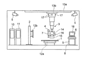
被検体をX線撮影する検査室の室内には、臥位撮影台1と立位撮影台2とが位置固定に
設置されている。本発明の一実施形態のX線撮影装置は、図1に示すように、室内の天井部分に移動可能に設置されたX線管14等の保持装置3と、室内を撮影するカメラ4、5と、X線条件入力部6、7と、メイン制御部8と、画像処理部9と、X線制御部10と、機械制御部11とを備えている。
In the room of the examination room for X-ray imaging of the subject, the standing position imaging table 1 and the standing position imaging table 2 are installed in a fixed position. As shown in FIG. 1, an X-ray imaging apparatus according to an embodiment of the present invention includes a
臥位撮影台1にはX線検出部12aが設けられ、被検体のX線撮影時には被検体がX線検出部12aに対向する位置に臥位姿勢で載せられる。立位撮影台2にはX線検出部12bが設けられ、被検体のX線撮影時には被検体がX線検出部12bに対向する位置に立位姿勢で立たされる。
The
室内の天井部分には固定ガイドレール13aが固定され、この固定ガイドレール13aには移動可能に可動ガイドレール13bが取付けられ、可動ガイドレール13bに移動可能に保持装置3が支持されている。なお、固定ガイドレール13aに対する可動ガイドレール13bの移動方向と、可動ガイドレール13bに対する保持装置3の移動方向とは互いに直交する方向とされている。
A
保持装置3には、カメラ4と、X線条件入力部7と、X線を出射するX線管14と、出射されたX線の照射範囲を絞るX線絞り装置15と、スピーカ16と、LEDなどの発光体17とが保持されている。保持装置3は、固定ガイドレール13a及び可動ガイドレール13bに沿って移動することにより、臥位撮影台1に設けられたX線検出部12aに対向する撮影位置、又は、立位撮影台2に設けられたX線検出部12bに対向する撮影位置に移動する。
The
カメラ4、5は室内を撮影するために用いられるもので、一方のカメラ4は保持装置3に保持され、他方のカメラ5は室内の天井部分に取付けられている。カメラ4、5の設置場所、設置数について特に制約はなく、保持装置3が移動する範囲内における室内の障害物(例えば、室内に居る術者や室内に置かれている周辺機器)を撮影できる場所、数であればよい。また、カメラ4、5の形態としては、CCDカメラ、CMOSカメラ、赤外線カメラ等のいずれでもよい。
The
X線条件入力部6、7では、撮影術式、撮影部位、被検体の体厚などに応じた撮影プロトコルの選択・設定などのX線による撮影条件の設定が行われる。一方のX線条件入力部6はメイン制御部8や画像処理部9と共に室内に設置され、他方のX線条件入力部7は保持装置3に保持されている。X線条件入力部6には、設定した条件やX線撮影された画像を表示する表示部18が設けられ、X線条件入力部7にも同様の表示部が設けられている。
The X-ray
メイン制御部8では、X線条件入力部6、7からの情報に基づき、X線撮影装置の各部、例えば、画像処理部9やX線制御部10や機械制御部11等の制御が行われる。
The
画像処理部9では、X線検出部12a、12bで検出したX線に基づいて可視化可能なX線画像が生成されるとともに、カメラ4、5で撮影した情報の処理が行われる。
The
X線制御部10では、メイン制御部8からの情報に基づき、X線管14から出射するX線の量、タイミング等の制御が行われる。
The
機械制御部11では、メイン制御部8からの情報に基づき、保持装置3の移動制御が行われる。なお、保持装置3の移動制御は、後述するモータ26を駆動することにより行われる。
In the
スピーカ16からは、保持装置3の移動中に保持装置3が障害物に対して設定距離以内に近付いた場合に警報音が発報され、障害物が設定距離以内に近付いたことが報知される。
The
発光体17は、保持装置3の周囲の4面に設けられており、保持装置3の移動方向の前方側に位置する発光体17が発光する。発光体17の発光方式は、連続した発光でもよく、又は、点滅でもよい。また、発光体17としてはLED以外に、ELパネルを使用してもよい。
The
図2は、X線撮影装置を構成する各構成部の電気的な接続状態を示している。 FIG. 2 shows an electrical connection state of each component constituting the X-ray imaging apparatus.
X線条件入力部6、7がメイン制御部8に接続され、メイン制御部8には、画像処理部9と、X線制御部10と、機械制御部11と、スピーカ制御部19と、発光体制御部20とが接続されている。
X-ray
画像処理部9には、カメラ4、5と、X線条件入力部6、7から入力されたX線による撮影条件や画像処理部9で生成したX線画像等を表示する表示部18と、画像処理部9で生成したX線画像やカメラ4、5で撮影した情報を記憶する画像記憶部21と、X線検出部12a、12bで検出したX線の信号を処理する画像信号処理部22と、カメラ4、5で撮影した情報に基づいて障害物の位置を算出する障害物位置算出部23とが接続されている。障害物位置算出部23には、この障害物位置算出部23での算出結果に基づいて臥位撮影台1又は立位撮影台2までの保持装置3の移動ルートを算出する移動ルート算出部24が接続されている。なお、障害物位置算出部23と移動ルート算出部24とは、メイン制御部8にも接続されている。
The
X線制御部10は、高電圧発生部25を介してX線管14に接続されている。
The
機械制御部11にはモータ26が接続され、モータ26には保持装置3が連結されている。モータ26が駆動されることにより、保持装置3が固定ガイドレール13a、可動ガイドレール13b沿って移動する。
A
障害物位置算出部23では、カメラ4、5で撮影した情報に基づいて室内の障害物の位置を常に算出しており、メイン制御部8では移動中の保持装置3と室内の障害物との位置を把握することができる。そして、保持装置3と障害物との距離が設定距離以内に近付いた場合、機械制御部11を制御することにより保持装置3の移動を抑制(減速、停止)する手段がメイン制御部8に設けられている。
The obstacle
さらに、メイン制御部8には、保持装置3と障害物との距離が設定距離以内に近付いた場合、スピーカ制御部19を制御することによりスピーカ16から警報音を発報することにより報知を行わせる手段が設けられている。
Further, when the distance between the
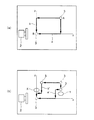
図3は、初期スタート位置(A位置)に位置する保持装置3を目的とする撮影位置(B位置)に移動させる場合に算出される移動ルートを示している。なお、移動ルートの算出は、目的とする撮影位置を中心とする座標軸に基づいて行われる。
FIG. 3 shows a movement route calculated when the
図3の(a)は、移動ルートとしてa、bの2つが算出された場合を示している。この移動ルートa、bの算出は、目的とする撮影位置までの移動距離が最短になるように、及び、目的とする撮影位置までの間での移動方向の切替数が最少となるように行われる。保持装置3が移動する場合には、いずれか一方の移動ルートが選択される。
FIG. 3A shows a case in which two movement routes a and b are calculated. The movement routes a and b are calculated so that the movement distance to the target photographing position is the shortest and the number of switching of the moving direction between the target photographing positions is the smallest. Is called. When the holding
図3の(b)は、移動ルートa、bを算出して移動を開始した後に、算出した移動ルート上に障害物X、Yが入り込んだ場合を示している。その場合には、途中から新たな移動ルートa´、b´が算出され、保持装置3は新たに算出された移動ルートa´、b´上に沿って移動する。移動ルートa´、b´の算出においては、目的とする撮影位置までの移動距離が最短になるように、及び、目的とする撮影位置までの間の移動方向の切替数が最少となるように行われる。
FIG. 3B shows a case where obstacles X and Y enter the calculated movement route after the movement routes a and b are calculated and the movement is started. In this case, new movement routes a ′ and b ′ are calculated from the middle, and the holding
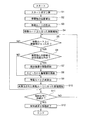
図4は、保持装置3の移動動作を説明するフローチャートである。保持装置3の目的とする撮影位置が指定されて保持装置3の移動を開始させるスタートボタンが押されると(ステップS1)、カメラ4、5で撮影した情報に基づいて障害物の位置が算出され(ステップS2)、障害物に衝突しない移動ルートが算出され(ステップS3)、その移動ルート上に沿って保持装置3の移動が開始される(ステップS4)。
FIG. 4 is a flowchart for explaining the movement operation of the holding
保持装置3の移動が開始された後も、カメラ4、5で撮影した情報に基づいて障害物の位置が算出されており、移動ルート上に障害物が入ったか否かがメイン制御部8で判断される(ステップS5)。
Even after the movement of the holding
移動ルート上に障害物が入った場合には(ステップS5のYES)、障害物との距離が設定距離以内であるか否かがメイン制御部8で判断される(ステップS6)。
If an obstacle enters the moving route (YES in step S5), the
障害物との距離が設定距離以内である場合には(ステップS6のYES)、保持装置3の移動が抑制(減速、停止)され(ステップS7)、スピーカ16から警報音が発報される(ステップS8)。その後、移動ルート算出部24において移動ルートが再算出され(ステップS9)、再算出された移動ルート上に沿った移動が開始される(ステップS10)。ここで、移動ルート算出部24は、一度設定した移動ルート上に障害物が入った場合、その障害物を避ける移動ルートを再度算出する手段として機能する。
If the distance from the obstacle is within the set distance (YES in step S6), the movement of the holding
その後、目的とする撮影位置に到達したか否かが判断され(ステップS11)、目的とする撮影位置に到達していれば保持装置3の移動が終了する(ステップS12)。到達していない場合には(ステップS11のNO)、ステップS5に戻る。
Thereafter, it is determined whether or not the target shooting position has been reached (step S11). If the target shooting position has been reached, the movement of the holding
ステップS5において、移動ルート上に障害物が入っていないと判断された場合には(ステップS5のNO)、ステップS11の判断が行われる。 If it is determined in step S5 that there is no obstacle on the moving route (NO in step S5), the determination in step S11 is performed.
ステップS6において、障害物までの距離が設定距離以内でないと判断された場合には(ステップS6のNO)、ステップS9で移動ルートが再算出される。 If it is determined in step S6 that the distance to the obstacle is not within the set distance (NO in step S6), the travel route is recalculated in step S9.
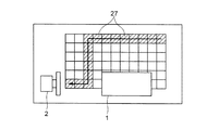
図5は、臥位撮影台1や立位撮影台2が設置された室内の床に設けられた複数の床側発光体27を示している。これらの床側発光体27としては、LEDやELパネル等が用いられている。これらの床側発光体27は、保持装置3が移動する場合、その移動に伴って保持装置3が移動する方向の前方側に位置する床側発光体27が順次発光する。例えば、保持装置3が立位姿勢の被検体を撮影する目的位置まで矢印で示す移動ルート上を移動する場合、その移動ルート上に位置する斜線で示した床側発光体27が、移動する保持装置3を先導するように保持装置3の移動に伴って順次発光する。
FIG. 5 shows a plurality of floor-side
このような構成において、保持装置3の目的とする撮影位置が指定されてスタートボタンが押されると、図4のフローチャートで説明したように、カメラ4、5で撮影した室内の障害物の位置が算出され、障害物に衝突しない移動ルートが算出され、その移動ルート上に沿って保持装置3が移動する。したがって、目的とする撮影位置に向けて室内を移動する保持装置3が室内の障害物に衝突することを防止することができ、X線撮影装置の安
全性を向上させることができ、及び、X線撮影の効率化を図ることができる。
In such a configuration, when the target photographing position of the holding
保持装置3が移動を開始した後に、移動ルート上に障害物が入り込んだ場合には、その障害物に衝突しない移動ルートが再度算出され、再度算出された移動ルート上に沿って保持装置3が移動する。したがって、保持装置3が移動を開始した後にその移動ルート上に障害物が入り込んだ場合でも、保持装置3がその障害物に衝突することを防止することができる。
When an obstacle enters the moving route after the
また、移動ルート上に障害物が入り込んだ場合には、保持装置3がその障害物に対して設定距離以内に近付いているか否かが判断され、設定距離以内に近付いている場合には、保持装置3の移動が抑制されて減速又は停止され、さらに、スピーカ16から警報音が発報される。このため、移動している保持装置3の移動ルート上に障害物が急に入り込んだ場合でも、保持装置3との衝突を防止することができる。
Further, when an obstacle enters the moving route, it is determined whether or not the holding
保持装置3が目的とする撮影位置に移動する場合、保持装置3に設けられている発光体17のうち、保持装置3の移動方向の前方側に位置する発光体17が発光する。このため、室内の術者が発光体17の発光状態を見ることにより保持装置3の移動方向を予測することができ、保持装置3との衝突を未然に防止することができる。
When the holding
また、保持装置3が目的とする撮影位置に移動する場合、室内の床に設けられている床側発光体27のうち、保持装置3の移動する方向の前方側に位置する床側発光体27が順次発光する。このため、室内の術者が床側発光体27の発光状態を見ることにより保持装置3の移動方向を予測することができ、保持装置3との衝突を未然に防止することができる。
Further, when the holding
なお、本実施形態では、カメラ4を室内の障害物を撮影するために用いる場合について説明したが、カメラ4を回動可能とし、被検体におけるX線照射部位をカメラ4で撮影可能としてもよい。被検体におけるX線照射部位をカメラ4で撮影し、その撮影画像を表示部18に表示することにより、X線が正しい位置に照射されるか否かを判定することができる。
In the present embodiment, the case where the camera 4 is used for photographing an obstacle in the room has been described. However, the camera 4 may be rotatable and the X-ray irradiation site in the subject may be photographed by the camera 4. . It is possible to determine whether or not the X-rays are irradiated to the correct position by imaging the X-ray irradiation site in the subject with the camera 4 and displaying the captured image on the
また、本実施形態では、障害物が保持装置3に対して設定距離以内に近付いた場合の報知を、保持装置3に設けたスピーカ16から警報音を発報させて行う場合を例に挙げて説明したが、このようなスピーカを室内に位置固定に設置してもよい。また、障害物が保持装置3に対して設定距離以内に近付いた場合の報知を、表示部18において文字表示で行うようにしてもよい。
Moreover, in this embodiment, the case where the notification when an obstacle approaches within the set distance to the
また、本実施形態では、床に設けた床側発光体27を、保持装置3が移動する方向の前方側に位置するものを順次発光させる場合を例に挙げて説明したが、さらに、保持装置3が移動する撮影位置に位置する床側発光体27を発光させるようにしてもよい。この場合には、保持装置3の移動ルートを示すための床側発光体27の発光と区別できるようにすることが望ましく、例えば、発光する色を変えたり、点滅状態で発光させるようにする。このように、保持装置3が移動する撮影位置をも示すことにより、室内に居る術者は保持装置3の移動方向をより確実に予測することができ、保持装置3との衝突をより一層防止することができる。
In the present embodiment, the case where the floor-side
以上説明した本発明の実施形態は、例として提示したものであり、発明の範囲を限定することは意図していない。この新規な実施形態は、その他の様々な形態で実施されることが可能であり、発明の要旨を逸脱しない範囲で、様々の省略、置き換え、変更を行うことができる。この実施形態やその変更は、発明の範囲や要旨に含まれるとともに、特許請求
の範囲に記載された発明とその均等の範囲に含まれる。
The embodiment of the present invention described above is presented as an example, and is not intended to limit the scope of the invention. The novel embodiment can be implemented in various other forms, and various omissions, replacements, and changes can be made without departing from the scope of the invention. This embodiment and its modifications are included in the scope and gist of the invention, and are included in the invention described in the claims and the equivalents thereof.
1 臥位撮影台(撮影台)
2 立位撮影台(撮影台)
3 保持装置
4、5 カメラ
12a、12b X線検出部
14 X線管
17 発光体
23 障害物位置算出部
24 移動ルート算出部
27 床側発光体
1 Supine stand (shooting stand)
2 Standing stand (shooting stand)
3
Claims (7)
前記保持装置が設置された室内を撮影するカメラと、
前記カメラで撮影した情報から前記室内の障害物の位置を算出する障害物位置算出部と、
前記障害物に衝突しないように前記保持装置を前記撮影位置に移動させる手段と、
を備えることを特徴とするX線撮影装置。 A holding device that holds an X-ray tube and is movable to an imaging position facing an X-ray detection unit provided on an imaging table;
A camera for photographing the room in which the holding device is installed;
An obstacle position calculating unit for calculating the position of the obstacle in the room from information photographed by the camera;
Means for moving the holding device to the photographing position so as not to collide with the obstacle;
An X-ray imaging apparatus comprising:
The floor-side light emitter is provided on the floor in the room, and the floor-side light emitter located on the front side in the moving direction of the holding device emits light. The X-ray imaging apparatus described.
Priority Applications (1)
| Application Number | Priority Date | Filing Date | Title |
|---|---|---|---|
| JP2011072332A JP5743640B2 (en) | 2011-03-29 | 2011-03-29 | X-ray equipment |
Applications Claiming Priority (1)
| Application Number | Priority Date | Filing Date | Title |
|---|---|---|---|
| JP2011072332A JP5743640B2 (en) | 2011-03-29 | 2011-03-29 | X-ray equipment |
Publications (2)
| Publication Number | Publication Date |
|---|---|
| JP2012205681A true JP2012205681A (en) | 2012-10-25 |
| JP5743640B2 JP5743640B2 (en) | 2015-07-01 |
Family
ID=47186039
Family Applications (1)
| Application Number | Title | Priority Date | Filing Date |
|---|---|---|---|
| JP2011072332A Active JP5743640B2 (en) | 2011-03-29 | 2011-03-29 | X-ray equipment |
Country Status (1)
| Country | Link |
|---|---|
| JP (1) | JP5743640B2 (en) |
Cited By (5)
| Publication number | Priority date | Publication date | Assignee | Title |
|---|---|---|---|---|
| JP2017217143A (en) * | 2016-06-06 | 2017-12-14 | 東芝メディカルシステムズ株式会社 | X-ray diagnostic apparatus |
| JP2019010397A (en) * | 2017-06-30 | 2019-01-24 | キヤノン株式会社 | Radiographic system, radiographic method and program |
| JPWO2020235099A1 (en) * | 2019-05-23 | 2020-11-26 | ||
| JPWO2020240653A1 (en) * | 2019-05-27 | 2020-12-03 | ||
| US11617547B2 (en) | 2019-05-22 | 2023-04-04 | Canon Medical Systems Corporation | Medical image diagnostic system and medical image diagnostic apparatus |
Citations (7)
| Publication number | Priority date | Publication date | Assignee | Title |
|---|---|---|---|---|
| JPS6264504U (en) * | 1985-10-09 | 1987-04-22 | ||
| JPH08266536A (en) * | 1995-03-31 | 1996-10-15 | Hitachi Medical Corp | Medical x-ray system |
| JPH11178818A (en) * | 1997-10-01 | 1999-07-06 | Siemens Ag | Medical equipment |
| JP2002238888A (en) * | 2001-02-21 | 2002-08-27 | Hitachi Medical Corp | Medical X-ray equipment |
| JP2007244569A (en) * | 2006-03-15 | 2007-09-27 | Shimadzu Corp | Ceiling running suspension X-ray imaging system |
| JP2008148866A (en) * | 2006-12-15 | 2008-07-03 | Toshiba Corp | X-ray diagnostic imaging apparatus and movement control method |
| JP2008183220A (en) * | 2007-01-30 | 2008-08-14 | Toshiba Corp | X-ray CT apparatus and bed operation control method |
-
2011
- 2011-03-29 JP JP2011072332A patent/JP5743640B2/en active Active
Patent Citations (7)
| Publication number | Priority date | Publication date | Assignee | Title |
|---|---|---|---|---|
| JPS6264504U (en) * | 1985-10-09 | 1987-04-22 | ||
| JPH08266536A (en) * | 1995-03-31 | 1996-10-15 | Hitachi Medical Corp | Medical x-ray system |
| JPH11178818A (en) * | 1997-10-01 | 1999-07-06 | Siemens Ag | Medical equipment |
| JP2002238888A (en) * | 2001-02-21 | 2002-08-27 | Hitachi Medical Corp | Medical X-ray equipment |
| JP2007244569A (en) * | 2006-03-15 | 2007-09-27 | Shimadzu Corp | Ceiling running suspension X-ray imaging system |
| JP2008148866A (en) * | 2006-12-15 | 2008-07-03 | Toshiba Corp | X-ray diagnostic imaging apparatus and movement control method |
| JP2008183220A (en) * | 2007-01-30 | 2008-08-14 | Toshiba Corp | X-ray CT apparatus and bed operation control method |
Cited By (10)
| Publication number | Priority date | Publication date | Assignee | Title |
|---|---|---|---|---|
| JP2017217143A (en) * | 2016-06-06 | 2017-12-14 | 東芝メディカルシステムズ株式会社 | X-ray diagnostic apparatus |
| JP2019010397A (en) * | 2017-06-30 | 2019-01-24 | キヤノン株式会社 | Radiographic system, radiographic method and program |
| JP6991751B2 (en) | 2017-06-30 | 2022-01-13 | キヤノン株式会社 | Radiation imaging system, radiography method and program |
| US11617547B2 (en) | 2019-05-22 | 2023-04-04 | Canon Medical Systems Corporation | Medical image diagnostic system and medical image diagnostic apparatus |
| JPWO2020235099A1 (en) * | 2019-05-23 | 2020-11-26 | ||
| WO2020235099A1 (en) * | 2019-05-23 | 2020-11-26 | 株式会社島津製作所 | X-ray imaging device and method of using x-ray imaging device |
| JP7264242B2 (en) | 2019-05-23 | 2023-04-25 | 株式会社島津製作所 | X-ray imaging device and method of using the X-ray imaging device |
| JPWO2020240653A1 (en) * | 2019-05-27 | 2020-12-03 | ||
| WO2020240653A1 (en) * | 2019-05-27 | 2020-12-03 | 株式会社島津製作所 | X-ray imaging device and method for avoiding contact with obstacle for x-ray imaging device |
| JP7173321B2 (en) | 2019-05-27 | 2022-11-16 | 株式会社島津製作所 | X-ray imaging apparatus and obstacle contact avoidance method for X-ray imaging apparatus |
Also Published As
| Publication number | Publication date |
|---|---|
| JP5743640B2 (en) | 2015-07-01 |
Similar Documents
| Publication | Publication Date | Title |
|---|---|---|
| CN105078484B (en) | Environment identification auxiliary guide system and method for mobile diagnosis and treatment equipment | |
| JP5743640B2 (en) | X-ray equipment | |
| JP5927366B1 (en) | Medical system | |
| JP6123901B2 (en) | Mobile X-ray equipment | |
| US20170135667A1 (en) | Method And Device For Positioning An Emitter | |
| JP5155714B2 (en) | X-ray imaging device | |
| JP6056974B2 (en) | X-ray equipment | |
| JP5188819B2 (en) | Mobile X-ray equipment | |
| JP5945993B2 (en) | Radiography equipment | |
| JP6735109B2 (en) | X-ray imaging system | |
| JP5897728B2 (en) | User interface for X-ray positioning | |
| JP2010227376A (en) | Radiography equipment | |
| JP2017104200A5 (en) | ||
| US7566171B2 (en) | Device for recording projection images | |
| WO2014077269A1 (en) | X-ray diagnostic device | |
| JP2007244569A (en) | Ceiling running suspension X-ray imaging system | |
| JP2017001818A (en) | System for generating elevator hoistway shape information, method for generating hoistway shape information | |
| TW201838579A (en) | Method for operating a self-traveling floor treatment apparatus | |
| JP7264242B2 (en) | X-ray imaging device and method of using the X-ray imaging device | |
| WO2017077652A1 (en) | Mobile x-ray apparatus | |
| JP2016190016A (en) | X-ray diagnostic apparatus | |
| JP2014073311A (en) | MOVABLE TYPE X-ray IMAGE PHOTOGRAPHING DEVICE | |
| JP2012187322A (en) | X-ray ct apparatus | |
| JP7255669B2 (en) | X-ray imaging device | |
| US10614917B2 (en) | Medical apparatus and method of controlling a medical apparatus |
Legal Events
| Date | Code | Title | Description |
|---|---|---|---|
| A621 | Written request for application examination |
Free format text: JAPANESE INTERMEDIATE CODE: A621 Effective date: 20140205 |
|
| A977 | Report on retrieval |
Free format text: JAPANESE INTERMEDIATE CODE: A971007 Effective date: 20141020 |
|
| A131 | Notification of reasons for refusal |
Free format text: JAPANESE INTERMEDIATE CODE: A131 Effective date: 20141022 |
|
| A521 | Request for written amendment filed |
Free format text: JAPANESE INTERMEDIATE CODE: A523 Effective date: 20141212 |
|
| TRDD | Decision of grant or rejection written | ||
| A01 | Written decision to grant a patent or to grant a registration (utility model) |
Free format text: JAPANESE INTERMEDIATE CODE: A01 Effective date: 20150402 |
|
| A61 | First payment of annual fees (during grant procedure) |
Free format text: JAPANESE INTERMEDIATE CODE: A61 Effective date: 20150428 |
|
| R150 | Certificate of patent or registration of utility model |
Ref document number: 5743640 Country of ref document: JP Free format text: JAPANESE INTERMEDIATE CODE: R150 |
|
| S111 | Request for change of ownership or part of ownership |
Free format text: JAPANESE INTERMEDIATE CODE: R313115 Free format text: JAPANESE INTERMEDIATE CODE: R313117 |
|
| R350 | Written notification of registration of transfer |
Free format text: JAPANESE INTERMEDIATE CODE: R350 |
|
| S533 | Written request for registration of change of name |
Free format text: JAPANESE INTERMEDIATE CODE: R313533 |
|
| R350 | Written notification of registration of transfer |
Free format text: JAPANESE INTERMEDIATE CODE: R350 |