JP2012206046A - Vertical roller mill - Google Patents
Vertical roller mill Download PDFInfo
- Publication number
- JP2012206046A JP2012206046A JP2011074670A JP2011074670A JP2012206046A JP 2012206046 A JP2012206046 A JP 2012206046A JP 2011074670 A JP2011074670 A JP 2011074670A JP 2011074670 A JP2011074670 A JP 2011074670A JP 2012206046 A JP2012206046 A JP 2012206046A
- Authority
- JP
- Japan
- Prior art keywords
- classifier
- blade
- vertical
- rectifying
- roller mill
- Prior art date
- Legal status (The legal status is an assumption and is not a legal conclusion. Google has not performed a legal analysis and makes no representation as to the accuracy of the status listed.)
- Pending
Links
- 238000010298 pulverizing process Methods 0.000 claims description 20
- 239000000843 powder Substances 0.000 abstract description 6
- 239000013590 bulk material Substances 0.000 abstract 1
- 239000003245 coal Substances 0.000 description 55
- 239000003638 chemical reducing agent Substances 0.000 description 6
- 230000000694 effects Effects 0.000 description 6
- 239000012530 fluid Substances 0.000 description 6
- 239000002245 particle Substances 0.000 description 4
- 230000000630 rising effect Effects 0.000 description 3
- 239000000446 fuel Substances 0.000 description 2
- 230000002093 peripheral effect Effects 0.000 description 2
- 235000019738 Limestone Nutrition 0.000 description 1
- 239000004568 cement Substances 0.000 description 1
- 239000003610 charcoal Substances 0.000 description 1
- 238000002485 combustion reaction Methods 0.000 description 1
- 238000009499 grossing Methods 0.000 description 1
- 239000006028 limestone Substances 0.000 description 1
- 239000000463 material Substances 0.000 description 1
- 239000002994 raw material Substances 0.000 description 1
- 230000001105 regulatory effect Effects 0.000 description 1
- 239000000126 substance Substances 0.000 description 1
Images
Landscapes
- Crushing And Grinding (AREA)
Abstract
Description
本発明は、塊状の石炭、石灰岩等を粉砕して微粉とし、ボイラの燃料として、或はセメントの原料として供給する竪型ローラミルに関するものである。 The present invention relates to a vertical roller mill that pulverizes massive coal, limestone, etc., and supplies it as a fine powder and as a fuel for boilers or as a raw material for cement.
石炭を燃料とする石炭焚きボイラでは、塊状の石炭を竪型ローラミルにより粉砕して所定の粒径の微粉炭とし、微粉炭を搬送空気と共に燃焼装置であるバーナに供給している。 In a coal-fired boiler using coal as fuel, massive coal is pulverized by a vertical roller mill to form pulverized coal having a predetermined particle diameter, and the pulverized coal is supplied to a burner that is a combustion apparatus together with carrier air.
竪型ローラミルは、粉砕テーブル上に塊状の石炭を供給し、粉砕テーブル上を転動するローラにより塊状の石炭を粉砕し、粉砕された微粉炭は搬送空気で搬送されるが、バーナに供給される微粉炭が所定の径となる様に、竪型ローラミル内部に設けられた分級機によって分級している。 The vertical roller mill supplies massive coal on a grinding table, grinds massive coal with a roller that rolls on the grinding table, and the pulverized pulverized coal is conveyed by conveying air, but is supplied to the burner. The pulverized coal is classified by a classifier provided inside the vertical roller mill so as to have a predetermined diameter.
分級機は、円周方向に所定ピッチで配設され、鉛直方向に延在する様に設けられたブレードを垂直軸心を中心に回転させることで、ブレードを通過する微粉炭に遠心力を作用させ、遠心力と微粉炭の流入流速とのバランスで微粉炭の分級を行うものである。 The classifier is arranged at a predetermined pitch in the circumferential direction, and rotates the blade provided so as to extend in the vertical direction around the vertical axis, thereby applying centrifugal force to the pulverized coal passing through the blade. The pulverized coal is classified by the balance between the centrifugal force and the inflow velocity of the pulverized coal.
従来、ブレードに微粉炭が均等に流入する様にブレードを上方に向って拡径する様に傾斜させたものがある。 Conventionally, there is one in which the blade is inclined so as to expand its diameter upward so that pulverized coal uniformly flows into the blade.
上記した様に、分級機はブレードが流体及び微粉炭に与える遠心力を利用しているものであり、ブレードが傾斜していることで、ブレード下部の回転半径とブレード上部の回転半径に差が生じ、分級機の下部と上部とでは遠心力の差が生じ、分級性能に影響を及すことが考えられる。 As described above, the classifier uses the centrifugal force that the blade exerts on the fluid and pulverized coal, and the inclination of the blade causes a difference between the rotating radius of the lower part of the blade and the rotating radius of the upper part of the blade. As a result, there is a difference in centrifugal force between the lower part and the upper part of the classifier, which may affect the classification performance.
特許文献1に示される分級機では、ブレードを上下2段に分割して上部のブレードの後退角と下部のブレードの後退角とを異ならせ、分級性能を同等としている。
In the classifier shown in
一方、分級機に流入する微粉炭は、流体は流路抵抗の小さい経路を通過する性質に伴って、ブレードの下部を多く流れる傾向を有する。この為、ブレードに流入する微粉炭に不均一な流量分布が生ずる。この為、ブレードの一部しか分級に寄与せず、分級機の性能を充分に発揮できない。特許文献1に於いても、微粉炭の流量分布に対しては特に言及されていない。
On the other hand, the pulverized coal flowing into the classifier has a tendency that the fluid flows in the lower part of the blade in large quantities due to the property that the fluid passes through the path having a small flow resistance. For this reason, a non-uniform flow distribution occurs in the pulverized coal flowing into the blade. For this reason, only a part of the blade contributes to the classification, and the performance of the classifier cannot be exhibited sufficiently. Even in
本発明は斯かる実情に鑑み、分級機に流入する微粉の流量分布を均等化し、分級機の分級効率を向上させると共に分級機の上部から下部に至る分級性能の均一化を図り、分級機の分級効率を向上させた竪型ローラミルを提供するものである。 In view of such a situation, the present invention equalizes the flow distribution of fine powder flowing into the classifier, improves the classification efficiency of the classifier, and achieves uniform classification performance from the upper part to the lower part of the classifier. The present invention provides a vertical roller mill with improved classification efficiency.
本発明は、分級室を画成するハウジングと、前記分級室の下部に設けられた粉砕テーブルと、該粉砕テーブルに押圧され、塊状物を粉砕する加圧ローラと、前記分級室の上部に位置し、粉砕された粉体が空気混合流として通過する様配設された分級機とを具備する竪型ローラミルに於いて、該分級機は鉛直軸心を中心に回転する回転部を有し、該回転部は上下方向に延在し円周方向に所定ピッチで配設された所定枚数のブレードを有し、該ブレードを上下に複数分割する位置に整流リングが設けられた竪型ローラミルに係るものである。 The present invention includes a housing that defines a classification chamber, a pulverization table provided at a lower portion of the classification chamber, a pressure roller that is pressed by the pulverization table and pulverizes a lump, and an upper portion of the classification chamber. And a classifier equipped with a classifier disposed so that the pulverized powder passes as an air-mixed flow, the classifier has a rotating portion that rotates about a vertical axis, The rotating part has a predetermined number of blades extending in a vertical direction and arranged at a predetermined pitch in a circumferential direction, and relates to a vertical roller mill in which a rectifying ring is provided at a position where the blades are divided into a plurality of vertical directions. Is.
又本発明は、前記整流リングは、分級機の中心に向って高くなる様に傾斜した竪型ローラミルに係るものである。 Further, the present invention relates to a vertical roller mill in which the rectifying ring is inclined so as to become higher toward the center of the classifier.
又本発明は、前記整流リングは、水平である竪型ローラミルに係るものである。 Further, the present invention relates to a vertical roller mill in which the rectifying ring is horizontal.
又本発明は、前記整流リングが画成する上下の間隔、及び前記整流リングの傾斜は前記ブレードに流入する空気混合流の流量分布の偏りが減少する様に設定された竪型ローラミルに係るものである。 Further, the present invention relates to a vertical roller mill in which the vertical space defined by the rectifying ring and the inclination of the rectifying ring are set so that the deviation of the flow distribution of the air mixed flow flowing into the blade is reduced. It is.
本発明によれば、分級室を画成するハウジングと、前記分級室の下部に設けられた粉砕テーブルと、該粉砕テーブルに押圧され、塊状物を粉砕する加圧ローラと、前記分級室の上部に位置し、粉砕された粉体が空気混合流として通過する様配設された分級機とを具備する竪型ローラミルに於いて、該分級機は鉛直軸心を中心に回転する回転部を有し、該回転部は上下方向に延在し円周方向に所定ピッチで配設された所定枚数のブレードを有し、該ブレードを上下に複数分割する位置に整流リングが設けられたので、分級機に流入する混合流が高さ方向に分割され、均等化され、ブレードによる分級作用が増大し、分級効果が向上するという優れた効果を発揮する。 According to the present invention, the housing that defines the classification chamber, the pulverization table provided in the lower portion of the classification chamber, the pressure roller that is pressed by the pulverization table and pulverizes the lump, and the upper portion of the classification chamber And a classifier arranged to pass the pulverized powder as an air mixed flow, the classifier has a rotating part that rotates about a vertical axis. The rotating portion has a predetermined number of blades extending in the vertical direction and arranged at a predetermined pitch in the circumferential direction, and a rectifying ring is provided at a position where the blade is divided into a plurality of vertical portions. The mixed flow flowing into the machine is divided in the height direction and equalized, and the classifying effect by the blade is increased, and the classifying effect is improved.
以下、図面を参照しつつ本発明の実施例を説明する。 Embodiments of the present invention will be described below with reference to the drawings.
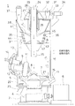
図1を参照して、本発明の第1の実施例に係る竪型ローラミル1を説明する。又、以下の説明図では、被粉砕物が石炭の場合を示している。
A
図中、実線は搬送空気の流れを示しており、点線は石炭の流れを示している。 In the figure, the solid line indicates the flow of the carrier air, and the dotted line indicates the flow of coal.
中空構造又は脚構造の基台2に筒状のハウジング3が立設され、該ハウジング3によって密閉された空間が形成される。該空間の下部には減速機4を介して粉砕テーブル5が立設され、前記減速機4は粉砕テーブルモータ6によって駆動され、前記粉砕テーブル5は前記減速機4によって定速又は可変速で回転される。
A
前記粉砕テーブル5の上面には、断面が円弧状の凹溝7を有するテーブルセグメント8が設けられている。
On the upper surface of the pulverizing table 5, a table segment 8 having a
前記粉砕テーブル5の回転中心から放射状に所要組数、例えば3組の加圧ローラユニット9が120°間隔で設けられている。該加圧ローラユニット9は、加圧ローラ11を有し、水平支持軸12を中心に傾動自在となっている。又、前記ハウジング3の下部には、放射状に貫通する3組のローラ加圧装置13が設けられている。該ローラ加圧装置13は、アクチュエータ、例えば油圧シリンダ14を具備し、該油圧シリンダ14によって前記加圧ローラ11を前記凹溝7に押圧する様になっている。
A required number of, for example, three sets of pressure roller units 9 are provided at 120 ° intervals radially from the center of rotation of the crushing table 5. The pressure roller unit 9 has a
前記粉砕テーブル5の下方には搬送空気室15が形成され、前記ハウジング3内部の前記粉砕テーブル5より上方は、分級室16となっている。
A
前記ハウジング3の下部には搬送空気供給口17が取付けられ、該搬送空気供給口17は、前記搬送空気室15に連通し、前記搬送空気供給口17を介して搬送空気が供給される。前記粉砕テーブル5の周囲には、搬送空気の吹出し口21が全周に設けられ、搬送空気は前記吹出し口21より前記分級室16に吹上げられる様になっている。
A carrier
又、前記粉砕テーブル5の下部には、該粉砕テーブル5と一体に回転可能な異物排出用スクレーパ22が2箇所に設けられており、前記搬送空気室15の底部には図示しない石炭排出機構に接続された異物排出シュート23が設けられている。
In addition, at the lower part of the pulverizing table 5, there are two foreign
前記ハウジング3の上側には石炭給排部24が設けられており、該石炭給排部24の中心部を貫通する様にパイプ状の給炭管25が設けられ、該給炭管25が前記ハウジング3の内部に延出し、下端が前記粉砕テーブル5の中央上方に位置している。前記給炭管25には石炭が供給され、供給された石炭は前記粉砕テーブル5の中心部に落下する様になっている。
A coal supply /
前記給炭管25には、回転管26が回転管支持部27に軸受28を介して回転自在に設けられている。前記回転管26は、プーリ29とプーリ31に掛渡されたベルト32及び前記プーリ31が設けられた減速機33を介して分級機モータ34によって回転される様になっている。
In the
又、前記回転管26、前記プーリ29、前記プーリ31、前記ベルト32、前記減速機33、前記分級機モータ34、回転部35によって分級機36が構成されている。
A
前記石炭給排部24には、粉砕された微粉炭を送給する微粉炭送給管37が接続されている。該微粉炭送給管37はボイラのバーナ(図示せず)に接続され、前記分級機36で分級された微粉炭をバーナに送給する。
A pulverized
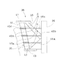
該分級機36を図2を参照して更に説明する。
The
前記回転管26に、前記回転部35が該回転管26と一体に鉛直軸心を中心に回転する様に設けられている。前記回転部35は、上支持リング41、支持部42、下支持リング43、ブレード44、整流リング45によって主に構成されている。
The rotating
更に、具体的に説明する。所要数のブレード支持アーム38が前記回転管26に放射状に設けられ、該ブレード支持アーム38の先端には上支持リング41が設けられ、前記回転管26の前記ブレード支持アーム38の下方に円錐形状の支持部42が設けられ、該支持部42に下支持リング43が設けられる。尚、前記ブレード44の下端を前記支持部42に支持させ、前記下支持リング43を省略してもよい。ここで、前記上支持リング41の中心径は、前記下支持リング43の中心径より大きくなっている。
Furthermore, it demonstrates concretely. A required number of
前記上支持リング41と前記下支持リング43とに掛渡って短冊状のブレード44が設けられ、該ブレード44は円周方向所定ピッチで所定数(例えば20枚から60枚)配設されている。従って、前記ブレード44は、上方に向って前記回転管26から離反する様に傾斜しており、水平とのなす角度はθとなっている。
A strip-shaped
前記ブレード44の中間に複数の整流リング45a,45b,45cが設けられる。該整流リング45a,45b,45cは、所要の板幅、即ち、微粉炭の流れに対して整流効果が発揮できる幅を有している。
A plurality of rectifying rings 45 a, 45 b and 45 c are provided in the middle of the
該整流リング45a,45b,45cと前記ブレード44との関係は、前記ブレード44を通しの部材とし、ブレード44,44間に整流リング45a,45b,45cを分割した円弧部材を掛渡して設けてもよい。或は、前記ブレード44を通しの部材とし、ブレード44の内径側、或は外径側に整流リング45a,45b,45cを固着してもよい。又、前記整流リング45a,45b,45cはそれぞれ、前記回転管26に設けたリング支持アーム46a,46b,46cにより適宜支持してもよい。該リング支持アーム46a,46b,46cで前記整流リング45a,45b,45cを支持することで、該整流リング45a,45b,45cの補強となり、該整流リング45a,45b,45cを薄肉にでき軽量化が図れる。
The relationship between the rectifying
前記下支持リング43と前記整流リング45aとの間隔、該整流リング45a,45b,45c間の間隔,整流リング45cと前記上支持リング41との間隔は等間隔であってもよく、或は下から上に向って広くしてもよい。後述する様に、前記整流リング45a,45b,45cは整流機能を有すると共に流れ抵抗となり、流量分布を調整する。
The distance between the
次に、前記竪型ミル1の作動について説明する。
Next, the operation of the
前記粉砕テーブル5が、前記減速機4を介して前記粉砕テーブルモータ6により回転され、図示しない空気ダクトから送給された200℃前後の搬送空気が、前記搬送空気供給口17より前記搬送空気室15に導入される。
The pulverizing table 5 is rotated by the pulverizing
前記給炭管25より塊状の石炭が投入されると、塊状の石炭は前記給炭管25の下端より前記粉砕テーブル5の中心部に流落し、該粉砕テーブル5上に供給される。該粉砕テーブル5上の石炭は、該粉砕テーブル5の回転による遠心力で外周方向に移動し、前記加圧ローラ11に噛込まれて粗粉炭と微粉炭からなる粉砕炭に粉砕され、更に遠心力によって外周に移動する。
When massive coal is introduced from the
前記搬送空気供給口17より前記搬送空気室15に導入された搬送空気が、前記粉砕テーブル5の前記吹出し口21より吹上がり、遠心力によって前記テーブルセグメント8を乗越えた粉砕炭は、前記吹出し口21から吹上がった搬送空気に乗って空気混合流として前記分級室16の外周部を前記ハウジング3の壁面に沿って上昇する。
The carrier air introduced into the
前記分級室16の外周を搬送空気に乗って上昇する粉砕炭は、粒径の大きい一部の粗粉炭が上昇途中で自重により前記粉砕テーブル5上に落下し、残りの粗粉炭及び微粉炭は、搬送空気に乗って、前記分級室16を更に上昇する。
The pulverized coal rising on the outer circumference of the
該分級室16を上昇する粗粉炭及び微粉炭流(空気混合流)は、搬送空気と共に前記分級機36に流入する。
Coarse pulverized coal and pulverized coal flow (air mixed flow) rising in the
該分級機36に流入する粗粉炭及び微粉炭流は、前記整流リング45a,45b,45cによって垂直方向に分割され、更に前記整流リング45a,45b,45cによって前記ブレード44に対して直角又は直角に近づく様に整流される。又分割されることで、下側の前記下支持リング43と前記整流リング45a、及び前記整流リング45a,45b間、前記整流リング45b,45c間、及び前記整流リング45cと前記上支持リング41間の各間隔に於ける圧力バランスを均一に向わせる作用が働くことで、前記ブレード44を通過する流量分布が均一化する。
Coarse and pulverized coal flows flowing into the
粗粉炭及び微粉炭流は、前記分級機モータ34によって回転する前記ブレード44を横切る際に、所定の粒径以上の粗粉炭は回転の遠心力によって外側へ押戻され、又は前記ブレード44と衝突して弾かれ、前記粉砕テーブル5上に落下する。又、所定の粒径以下の微粉炭は搬送空気に乗って前記ブレード44を横切り、前記微粉炭送給管37より送出され、ボイラのバーナ(図示せず)に供給される。
When the pulverized coal and the pulverized coal flow cross the
前記ブレード44によって弾き飛ばされた粗粉炭は、前記粉砕テーブル5上に落下し、落下した粗粉炭は、前記粉砕テーブル5の回転遠心力によって前記凹溝7迄移動し、前記加圧ローラ11によって再度粉砕される。
The pulverized coal blown off by the
又、前記下支持リング43と前記整流リング45aとの間隔、該整流リング45a,45b,45c間の間隔、前記整流リング45cと前記上支持リング41との間隔は下から上に向って広くしてもよい。前記間隔が狭い方が流路抵抗が大きくなるので、前記分級機36の下側の間隔を小さくすることで、微粉炭流の上側への分配量がより増大し、流量分布が一層均等化する。
The distance between the
而して、前記ブレード44の全長が分級に寄与することになるので分級効率が増大する。
Thus, since the entire length of the
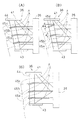
図3(A)は、第2の実施例を示している。 FIG. 3A shows a second embodiment.
第2の実施例では、前記整流リング45a,45b,45cに対して角度を付けたものである。該整流リング45a,45b,45cの角度は、例えば前記ブレード44に対して直角とする。前記整流リング45a,45b,45cに角度を付けることで、該整流リング45a,45b,45cの形状は円錐曲面をリング状に切出したものとなる。
In the second embodiment, the rectifying rings 45a, 45b and 45c are angled. The angles of the rectifying rings 45a, 45b, 45c are set to be perpendicular to the
図3(B)は第3の実施例を示している。該第3の実施例では、前記整流リング45a,45b,45cに角度を付け、該角度を上方に向う程、大きく設定したものである。例えば、最下段の整流リング45aは水平とし、前記整流リング45bが水平となす角度をα、前記整流リング45cが水平となす角度を2αとする等である。尚、整流リング45a,45b,45cの角度は、流量分布の偏りが解消される様に設定されればよい。
FIG. 3B shows a third embodiment. In the third embodiment, the rectifying rings 45a, 45b, 45c are provided with an angle, and the angle is set to be larger as it goes upward. For example, the
第3の実施例では、下段程角度が小さくなることで、流体の流れ方向との相対的な角度が大きくなり、その分流路抵抗が大きくなり、上方への流体の分配量が大きくなる。又、図示していないが、前記整流リング45a,45b,45c間の間隔を変え、更に角度を変える様にしてもよい。
In the third embodiment, since the angle at the lower stage becomes smaller, the angle relative to the fluid flow direction becomes larger, the flow path resistance is increased accordingly, and the amount of fluid distributed upward is increased. Although not shown, the intervals between the rectifying
図3(C)は第4の実施例を示している。該第4の実施例では、前記ブレード44の角度θを90゜、即ち鉛直としたものであり、前記整流リング45a,45b,45cの間隔、角度を調整することで、前記ブレード44全長に亘る流量分布を均一化したものである。前記ブレード44を鉛直とすることで、該ブレード44の上部、下部での回転半径が同一となり、遠心力の差がなくなるので、分級性能にバラツキがなくなる。
FIG. 3C shows a fourth embodiment. In the fourth embodiment, the angle .theta. Of the
尚、上記実施例では、3の整流リング45a,45b,45cにより、分級機の流入部を上下に4分割したが、2又は3分割、或は5分割以上としてもよい。又、分割数が多くなりすぎると、流路抵抗が大きくなりすぎる。又、重量が増大する等の問題があるので、実用的には3分割から5分割が好ましい。
In the above embodiment, the inflow portion of the classifier is divided into four parts vertically by the three rectifying
又、前記整流リング45a,45b,45cの幅(半径方向の寸法)は、整流効果に合わせて適宜決定される。又、整流リング45a,45b,45cの外周は前記ブレード44の外端と同じである必要はなく、外側に食み出しても構わない。この場合、ブレード44の1/3程度迄とする。又、中心側への食み出し量は、整流効果を考慮して、ブレード44の1/2以上の長さは必要とする。
The widths (radial dimensions) of the rectifying rings 45a, 45b, and 45c are appropriately determined according to the rectifying effect. Further, the outer circumferences of the rectifying rings 45a, 45b, 45c need not be the same as the outer ends of the
又、整流リング45a,45b,45cの角度は、前記ブレード44に対して直角からの傾き角度+15度迄の角度ならば構わない。分級機36のブレード44の傾きに合わせて外側に向って下向きの角度を持たせることで、流体の流入をスムーズにし、ブレード44に対して垂直方向に整流する効果が期待される。
The angle of the rectifying rings 45a, 45b, 45c may be an angle up to a tilt angle +15 degrees with respect to the
1 竪型ローラミル
3 ハウジング
5 粉砕テーブル
9 加圧ローラユニット
11 加圧ローラ
15 搬送空気室
16 分級室
26 回転管
35 回転部
36 分級機
41 上支持リング
42 支持部
43 下支持リング
44 ブレード
45 整流リング
DESCRIPTION OF
Claims (4)
Priority Applications (1)
| Application Number | Priority Date | Filing Date | Title |
|---|---|---|---|
| JP2011074670A JP2012206046A (en) | 2011-03-30 | 2011-03-30 | Vertical roller mill |
Applications Claiming Priority (1)
| Application Number | Priority Date | Filing Date | Title |
|---|---|---|---|
| JP2011074670A JP2012206046A (en) | 2011-03-30 | 2011-03-30 | Vertical roller mill |
Publications (1)
| Publication Number | Publication Date |
|---|---|
| JP2012206046A true JP2012206046A (en) | 2012-10-25 |
Family
ID=47186318
Family Applications (1)
| Application Number | Title | Priority Date | Filing Date |
|---|---|---|---|
| JP2011074670A Pending JP2012206046A (en) | 2011-03-30 | 2011-03-30 | Vertical roller mill |
Country Status (1)
| Country | Link |
|---|---|
| JP (1) | JP2012206046A (en) |
Cited By (1)
| Publication number | Priority date | Publication date | Assignee | Title |
|---|---|---|---|---|
| CN117065865A (en) * | 2023-10-07 | 2023-11-17 | 湖南华电平江发电有限公司 | A coal grinder that can reduce flow resistance and prevent spontaneous combustion |
Citations (2)
| Publication number | Priority date | Publication date | Assignee | Title |
|---|---|---|---|---|
| JPS5949855A (en) * | 1982-09-14 | 1984-03-22 | 太平洋セメント株式会社 | Shaft type mill |
| JPH05208172A (en) * | 1992-01-30 | 1993-08-20 | Ube Ind Ltd | Classification method and classifier |
-
2011
- 2011-03-30 JP JP2011074670A patent/JP2012206046A/en active Pending
Patent Citations (2)
| Publication number | Priority date | Publication date | Assignee | Title |
|---|---|---|---|---|
| JPS5949855A (en) * | 1982-09-14 | 1984-03-22 | 太平洋セメント株式会社 | Shaft type mill |
| JPH05208172A (en) * | 1992-01-30 | 1993-08-20 | Ube Ind Ltd | Classification method and classifier |
Cited By (1)
| Publication number | Priority date | Publication date | Assignee | Title |
|---|---|---|---|---|
| CN117065865A (en) * | 2023-10-07 | 2023-11-17 | 湖南华电平江发电有限公司 | A coal grinder that can reduce flow resistance and prevent spontaneous combustion |
Similar Documents
| Publication | Publication Date | Title |
|---|---|---|
| CN102430453B (en) | Polygonal adjustable air ring for roll mill | |
| CN105636700B (en) | The manufacture method of solid fuel reducing mechanism and solid fuel reducing mechanism | |
| US20070290088A1 (en) | Bowl mill for a coal pulverizer with an air mill for primary entry of air | |
| JP2023015281A (en) | mill | |
| JP5760591B2 (en) | Vertical roller mill | |
| JP6202259B2 (en) | Vertical mill and vertical mill classifier | |
| JP5782811B2 (en) | Vertical mill | |
| KR101634763B1 (en) | Vertical pulverizing apparatus | |
| JP5927992B2 (en) | Biomass mill | |
| KR101541426B1 (en) | Pulverizer having improved vane wheel | |
| JP5790086B2 (en) | Vertical mill | |
| JP2012206046A (en) | Vertical roller mill | |
| WO2013133446A1 (en) | Biomass mill | |
| JP5857629B2 (en) | Biomass mill | |
| JP5983214B2 (en) | Vertical mill | |
| JP5888131B2 (en) | Vertical mill | |
| JP2012217920A (en) | Vertical mill | |
| JP2017047383A (en) | Biomass mill | |
| JP6497079B2 (en) | Vertical crusher | |
| JP6248718B2 (en) | Vertical crusher | |
| JP5577668B2 (en) | Vertical roller mill | |
| JP6729066B2 (en) | Vertical crusher | |
| CN102369060B (en) | Roller mill | |
| JPH04256449A (en) | Vertical crusher | |
| JP6790501B2 (en) | Vertical crusher |
Legal Events
| Date | Code | Title | Description |
|---|---|---|---|
| A621 | Written request for application examination |
Free format text: JAPANESE INTERMEDIATE CODE: A621 Effective date: 20140122 |
|
| A977 | Report on retrieval |
Free format text: JAPANESE INTERMEDIATE CODE: A971007 Effective date: 20141110 |
|
| A131 | Notification of reasons for refusal |
Free format text: JAPANESE INTERMEDIATE CODE: A131 Effective date: 20141118 |
|
| A02 | Decision of refusal |
Free format text: JAPANESE INTERMEDIATE CODE: A02 Effective date: 20150310 |