JP2012206086A - Inkjet printer and control method for inkjet printer - Google Patents
Inkjet printer and control method for inkjet printer Download PDFInfo
- Publication number
- JP2012206086A JP2012206086A JP2011075804A JP2011075804A JP2012206086A JP 2012206086 A JP2012206086 A JP 2012206086A JP 2011075804 A JP2011075804 A JP 2011075804A JP 2011075804 A JP2011075804 A JP 2011075804A JP 2012206086 A JP2012206086 A JP 2012206086A
- Authority
- JP
- Japan
- Prior art keywords
- discharge
- curing light
- time
- head
- light irradiation
- Prior art date
- Legal status (The legal status is an assumption and is not a legal conclusion. Google has not performed a legal analysis and makes no representation as to the accuracy of the status listed.)
- Granted
Links
- 238000000034 method Methods 0.000 title claims abstract description 37
- 239000011344 liquid material Substances 0.000 claims abstract description 84
- 230000001678 irradiating effect Effects 0.000 claims abstract description 11
- 239000007788 liquid Substances 0.000 claims description 111
- 238000002347 injection Methods 0.000 claims description 72
- 239000007924 injection Substances 0.000 claims description 72
- 238000007599 discharging Methods 0.000 claims description 13
- 230000004044 response Effects 0.000 claims description 7
- 238000001723 curing Methods 0.000 description 150
- 230000007246 mechanism Effects 0.000 description 30
- 239000011295 pitch Substances 0.000 description 18
- 230000004048 modification Effects 0.000 description 15
- 238000012986 modification Methods 0.000 description 15
- 238000010586 diagram Methods 0.000 description 14
- 238000009281 ultraviolet germicidal irradiation Methods 0.000 description 12
- 230000005540 biological transmission Effects 0.000 description 9
- 238000012545 processing Methods 0.000 description 9
- 238000012423 maintenance Methods 0.000 description 8
- 239000000758 substrate Substances 0.000 description 8
- 230000003111 delayed effect Effects 0.000 description 7
- 238000005192 partition Methods 0.000 description 5
- 238000006243 chemical reaction Methods 0.000 description 4
- 230000008054 signal transmission Effects 0.000 description 4
- 230000008901 benefit Effects 0.000 description 3
- 239000003086 colorant Substances 0.000 description 3
- 230000008569 process Effects 0.000 description 3
- 230000000694 effects Effects 0.000 description 2
- 239000012530 fluid Substances 0.000 description 2
- 230000007257 malfunction Effects 0.000 description 2
- 238000004519 manufacturing process Methods 0.000 description 2
- 239000000463 material Substances 0.000 description 2
- 239000000203 mixture Substances 0.000 description 2
- 238000000016 photochemical curing Methods 0.000 description 2
- 230000008033 biological extinction Effects 0.000 description 1
- 230000015572 biosynthetic process Effects 0.000 description 1
- 230000000740 bleeding effect Effects 0.000 description 1
- 230000008859 change Effects 0.000 description 1
- 238000004891 communication Methods 0.000 description 1
- 238000013461 design Methods 0.000 description 1
- 230000005684 electric field Effects 0.000 description 1
- 230000001771 impaired effect Effects 0.000 description 1
- 238000007689 inspection Methods 0.000 description 1
- 238000012538 light obscuration Methods 0.000 description 1
- 230000005499 meniscus Effects 0.000 description 1
- 229910001507 metal halide Inorganic materials 0.000 description 1
- 150000005309 metal halides Chemical class 0.000 description 1
- 230000001737 promoting effect Effects 0.000 description 1
- 239000002002 slurry Substances 0.000 description 1
- 230000007480 spreading Effects 0.000 description 1
- 238000003892 spreading Methods 0.000 description 1
- 238000003860 storage Methods 0.000 description 1
- 239000000126 substance Substances 0.000 description 1
- 229920001187 thermosetting polymer Polymers 0.000 description 1
Images




Landscapes
- Coating Apparatus (AREA)
- Ink Jet (AREA)
Abstract
【課題】液状体が配置された被描画媒体の適切な位置に適切な量の硬化光を照射できるインクジェット描画装置、及びインクジェット描画装置の制御方法を提供する。
【解決手段】インクジェット描画装置は、光硬化型の液状体を吐出する吐出ノズルを備え、媒体保持手段に保持された被描画媒体に向けて液状体を吐出する吐出ヘッドと、液状体の硬化光を、被描画媒体に照射する硬化光照射手段と、吐出ヘッドと硬化光照射手段とを保持するヘッド保持手段と、被描画媒体と吐出ヘッドとを相対移動させるとともに、吐出ヘッドから液状体を吐出して被描画媒体に着弾させる吐出走査の吐出走査方向に、ヘッド保持手段と媒体保持手段とを相対移動させる相対走査手段と、吐出ヘッドを制御する吐出制御手段と、硬化光照射手段を制御する硬化光照射制御手段と、を備え、硬化光照射制御手段は、吐出制御手段が発信する吐出制御信号に基づいて、硬化光照射手段を制御する。
【選択図】図4An inkjet drawing apparatus capable of irradiating an appropriate position of a drawing medium on which a liquid material is disposed with an appropriate amount of curing light, and a method for controlling the inkjet drawing apparatus.
An inkjet drawing apparatus includes a discharge nozzle that discharges a photocurable liquid material, a discharge head that discharges the liquid material toward a drawing medium held by the medium holding means, and a curing light for the liquid material. Irradiating the drawing medium with the curing light irradiation means, the head holding means for holding the ejection head and the curing light irradiation means, the drawing medium and the ejection head are relatively moved, and the liquid material is ejected from the ejection head. The relative scanning means for relatively moving the head holding means and the medium holding means in the ejection scanning direction of the ejection scanning to be landed on the drawing medium, the ejection control means for controlling the ejection head, and the curing light irradiation means are controlled. Curing light irradiation control means, and the curing light irradiation control means controls the curing light irradiation means based on a discharge control signal transmitted from the discharge control means.
[Selection] Figure 4
Description
本発明は、液状体を液滴として吐出して被描画媒体上に着弾させることによって、被描画媒体上に液状体を配置し、配置した液状体を硬化させることによって被描画媒体上に画像を描画するインクジェット描画装置、及び当該インクジェット描画装置の制御方法に関する。 In the present invention, the liquid material is ejected as droplets and landed on the drawing medium, the liquid material is arranged on the drawing medium, and the arranged liquid material is cured to form an image on the drawing medium. The present invention relates to an ink jet drawing apparatus for drawing, and a method for controlling the ink jet drawing apparatus.
従来から、吐出ヘッドから液状体を液滴として吐出し、任意の位置に精度よく着弾させることによって、任意の位置に任意の量の液状体を配置するインクジェット装置が知られている。このようなインクジェット装置は、配置した液状体を硬化させることによって、精密な形状を有する機能膜や、精細な画像などを形成することができる製膜装置として用いられる。
特許文献1には、粘度調整されたインクをインクジェットヘッドの吐出口から吐出して被印刷物に塗着し、塗着されたインクの滲み開始前に当該インクの一部または全部を硬化する工程を有することで、小さい文字や記号をマーキング可能な電子部品の製造方法及び電子部品の製造装置が開示されている。
2. Description of the Related Art Conventionally, there is known an ink jet apparatus in which an arbitrary amount of liquid material is disposed at an arbitrary position by discharging the liquid material as droplets from an ejection head and landing on the arbitrary position with high accuracy. Such an ink jet apparatus is used as a film forming apparatus capable of forming a functional film having a precise shape, a fine image, or the like by curing a liquid material disposed.
しかし、特許文献1に開示された方法では、インクなどの液状体を硬化させるための紫外線などの硬化光が、当該硬化光を照射することが必要な部分以外にも照射されていた。例えば、インクジェットヘッドの吐出口の周辺に硬化光が照射されると、吐出口内の液状体の硬化が進行し、適切な吐出が損なわれる可能性がある。また、被印刷媒体に照射されると、照射された硬化光によって供給される熱エネルギーに起因する熱膨張などによって、照射された部分のみが変形する可能性がある。このため、硬化光が照射される領域は、必要な範囲に限定できることが好ましい。
特許文献2には、印刷部の情報を取得するリニアエンコーダーと、リニアエンコーダーによって取得された印刷部の位置情報に基づいて、UV照射手段のUV照射範囲が印刷部からUVインクが吐出された範囲内となるようにUV照射手段からのUV照射を制御するUV照射範囲制御手段と、を備えることによって不要な部分にUV光を照射することを防止することができるインクジェットプリンタ及びその制御方法が開示されている。
However, in the method disclosed in
しかしながら、特許文献2に開示されたような装置又は方法では、リニアエンコーダーに不具合が発生した場合には、印刷部の誤った位置情報に基づいてUV光の照射が実施されるため、不適切な位置にもUV光が照射される可能性が高いという課題があった。また、UV光照射手段の移動装置に不具合が発生した場合には、照射対象物に対するUV光照射手段の移動速度が不適切になることに起因して、照射対象位置に対するUV光の照射時間が不適切になり、照射されるUV光の光量が不適切になるという課題があった。特に、同じ部分に硬化光が照射され続けた場合には、過多に照射された硬化光に起因する温度上昇などによって、被描画媒体が損なわれる可能性が高いという課題があった。
However, in the apparatus or method as disclosed in
本発明は、上記課題の少なくとも一部を解決するためになされたものであり、以下の形態又は適用例として実現することが可能である。 SUMMARY An advantage of some aspects of the invention is to solve at least a part of the problems described above, and the invention can be implemented as the following forms or application examples.
[適用例1]本適用例にかかるインクジェット描画装置は、光硬化型の液状体を配置して描画する対象物である被描画媒体を保持する媒体保持手段と、前記液状体の液滴を吐出する複数の吐出ノズルを備え、前記複数の吐出ノズルのそれぞれの吐出ノズルから、前記媒体保持手段に保持された前記被描画媒体に向けて、前記液状体の前記液滴を吐出する吐出ヘッドと、前記液状体の硬化を促進する硬化光を、前記媒体保持手段に保持された前記被描画媒体に向けて射出して、前記被描画媒体に前記硬化光を照射する硬化光照射手段と、前記吐出ヘッドと、前記硬化光照射手段と、を保持するヘッド保持手段と、前記被描画媒体と前記吐出ヘッドとを相対移動させるとともに、前記吐出ヘッドから前記液状体を吐出して前記被描画媒体に着弾させる吐出走査における、前記吐出ヘッドと前記被描画媒体との相対移動方向である吐出走査方向に、前記ヘッド保持手段と前記媒体保持手段とを相対移動させる相対走査手段と、前記吐出ヘッドを制御して前記液状体を吐出させる吐出制御手段と、前記硬化光照射手段を制御して前記硬化光を照射させる硬化光照射制御手段と、を備え、前記硬化光照射制御手段は、前記吐出制御手段が前記吐出ヘッドからの前記液状体の吐出を制御するために発信する吐出制御信号に基づいて、前記硬化光照射手段を制御して、前記硬化光照射手段を、前記硬化光を射出する射出状態、又は前記硬化光を射出しない射出停止状態にすることを特徴とする。 Application Example 1 In an ink jet drawing apparatus according to this application example, a medium holding means for holding a drawing medium which is an object to be drawn by arranging a photo-curing liquid material, and ejecting liquid droplets of the liquid material A discharge head that discharges the liquid droplets from the discharge nozzles of the plurality of discharge nozzles toward the drawing medium held by the medium holding unit; Curing light irradiating means for injecting curing light for accelerating curing of the liquid material toward the drawing medium held by the medium holding means and irradiating the drawing light on the drawing medium; and the ejection A head holding means for holding the head, the curing light irradiation means, the drawing medium and the discharge head are relatively moved, and the liquid is discharged from the discharge head to land on the drawing medium. The A relative scanning unit that relatively moves the head holding unit and the medium holding unit in a discharge scanning direction that is a relative movement direction of the ejection head and the drawing medium in the ejection scanning. Discharge control means for discharging the liquid material, and curing light irradiation control means for controlling the curing light irradiation means to irradiate the curing light, wherein the curing light irradiation control means includes the discharge control means. Based on a discharge control signal transmitted to control the discharge of the liquid material from the discharge head, the curing light irradiation unit is controlled, and the curing light irradiation unit emits the curing light. Alternatively, an injection stop state in which the curing light is not emitted is set.
本適用例にかかるインクジェット描画装置によれば、硬化光照射制御手段は、吐出制御手段が吐出ヘッドからの液状体の吐出を制御するために発信する吐出制御信号に基づいて、硬化光照射手段を、射出状態、又は射出停止状態にする。
硬化光照射手段は、吐出ヘッドから吐出されて被描画媒体上に着弾した液状体に硬化光を照射するために、硬化光を射出させられる。したがって、硬化光照射手段を射出状態にする必要が発生するのは、吐出ヘッドから被描画媒体に向けて液状体が吐出された場合である。吐出ヘッドからの液状体の吐出を制御するために発信される吐出制御信号に基づいて、硬化光照射手段を、射出状態、又は射出停止状態にすることで、必要な場合に合わせて、適切に、硬化光照射手段に硬化光を射出させることができる。また、硬化光を射出させることが不要な場合であるにもかかわらず、硬化光照射手段に硬化光を射出させることを抑制することができる。
According to the ink jet drawing apparatus according to this application example, the curing light irradiation control unit controls the curing light irradiation unit based on the discharge control signal that the discharge control unit transmits to control the discharge of the liquid material from the discharge head. To the injection state or the injection stop state.
The curing light irradiation means emits curing light to irradiate the liquid that has been ejected from the ejection head and landed on the drawing medium. Therefore, it is necessary to set the curing light irradiation means to the injection state when the liquid material is discharged from the discharge head toward the drawing medium. Based on the discharge control signal transmitted to control the discharge of the liquid material from the discharge head, the curing light irradiation means is appropriately set in accordance with the necessity when it is in the injection state or the injection stop state. The curing light can be emitted to the curing light irradiation means. Moreover, although it is a case where it is unnecessary to inject the curing light, it is possible to suppress the curing light from being emitted to the curing light irradiation unit.
[適用例2]上記適用例にかかるインクジェット描画装置において、前記吐出制御手段が、前記吐出ヘッドが備える前記複数の吐出ノズルにおけるいずれかの前記吐出ノズルからの前記液状体の吐出を指令する吐出指令信号を発信した場合に、前記硬化光照射制御手段は、前記硬化光照射手段を、前記射出状態にすることが好ましい。 Application Example 2 In the ink jet drawing apparatus according to the application example described above, the discharge control unit instructs the discharge control unit to discharge the liquid material from any one of the plurality of discharge nozzles provided in the discharge head. When the signal is transmitted, the curing light irradiation control means preferably places the curing light irradiation means in the injection state.
このインクジェット描画装置によれば、吐出制御手段が、吐出ノズルからの液状体の吐出を指令する吐出指令信号を発信した場合に、硬化光照射制御手段は、硬化光照射手段を、射出状態にする。硬化光照射手段は、吐出ヘッドから吐出されて被描画媒体上に着弾した液状体に硬化光を照射するために、硬化光を射出させられる。したがって、硬化光照射手段を射出状態にする必要が発生するのは、吐出ヘッドから被描画媒体に向けて液状体が吐出された場合である。吐出ノズルからの液状体の吐出を指令する吐出指令信号に基づいて、硬化光照射手段を、射出状態にすることで、必要な場合に合わせて、適切に、硬化光照射手段に硬化光を射出させることができる。 According to this ink jet drawing apparatus, the curing light irradiation control means puts the curing light irradiation means into an injection state when the discharge control means transmits a discharge command signal for instructing discharge of the liquid material from the discharge nozzle. . The curing light irradiation means emits curing light to irradiate the liquid that has been ejected from the ejection head and landed on the drawing medium. Therefore, it is necessary to set the curing light irradiation means to the injection state when the liquid material is discharged from the discharge head toward the drawing medium. Based on the discharge command signal that commands the discharge of the liquid material from the discharge nozzle, the curing light irradiation means is brought into the injection state, so that the curing light is appropriately emitted to the curing light irradiation means as necessary. Can be made.
[適用例3]上記適用例にかかるインクジェット描画装置において、前記硬化光照射制御手段は、前記液状体の吐出を指令する吐出指令信号に応じて、当該吐出指令信号が発信された時点から所定の第一遅延時間が経過した時点に、前記硬化光照射手段を前記射出状態にすることが好ましい。 Application Example 3 In the ink jet drawing apparatus according to the application example, the curing light irradiation control unit is configured to perform a predetermined operation from the time when the discharge command signal is transmitted in response to a discharge command signal that commands discharge of the liquid material. It is preferable that the curing light irradiation means is brought into the injection state when the first delay time has elapsed.
このインクジェット描画装置によれば、硬化光照射制御手段は、吐出指令信号が発信された時点から所定の第一遅延時間後に、硬化光照射手段を射出状態にする。一般的に、硬化光は、液状体が着弾してから、長い時間が経過することなく照射されることが好ましい。しかし、液滴が着弾する地点に、着弾と同時に硬化光を照射することができる位置に、吐出ヘッドと、硬化光照射手段とを、配置することは非常に困難である。また、液滴が着弾する地点に着弾と同時に硬化光を照射できたとすると、硬化光が吐出ノズルにも照射される可能性が高くなり、吐出ノズル内の吐出前の液状体に硬化光が照射されることによって、吐出ノズル内の液状体が硬化する可能性がある。したがって、硬化光は、液状体が着弾してから、適切な時間が経過した後に照射されることが好ましい。吐出指令信号が発信された時点から第一遅延時間経過した後時点に、硬化光照射手段を射出状態にすることで、液状体が着弾してから、第一遅延時間が経過した後に、硬化光を照射する状態にすることができる。 According to this ink jet drawing apparatus, the curing light irradiation control unit puts the curing light irradiation unit into an injection state after a predetermined first delay time from the time when the ejection command signal is transmitted. Generally, it is preferable that the curing light is irradiated without a long time elapses after the liquid material has landed. However, it is very difficult to dispose the ejection head and the curing light irradiation means at a position where the droplets can land at a position where the curing light can be irradiated simultaneously with the landing. In addition, if it is possible to irradiate curing light simultaneously with landing at the spot where the droplets land, the possibility that the curing light will be irradiated also to the discharge nozzle increases, and the liquid before discharge in the discharge nozzle is irradiated with the curing light. As a result, the liquid in the discharge nozzle may be cured. Therefore, it is preferable that the curing light is irradiated after an appropriate time has elapsed after the liquid has landed. By setting the curing light irradiation means to the injection state after the first delay time has elapsed from the time when the discharge command signal is transmitted, the curing light is emitted after the first delay time has elapsed since the liquid material landed. Can be in a state of irradiation.
[適用例4]上記適用例にかかるインクジェット描画装置において、前記硬化光照射制御手段は、前記液状体の吐出を指令する吐出指令信号が発信された時点から所定の経過時間が経過するまでに、前記吐出指令信号が発信されなかった場合に、前記硬化光照射手段を前記射出停止状態にすることが好ましい。 Application Example 4 In the ink jet drawing apparatus according to the application example described above, the curing light irradiation control unit is configured to allow a predetermined elapsed time to elapse from when a discharge command signal for instructing discharge of the liquid material is transmitted. When the discharge command signal is not transmitted, it is preferable that the curing light irradiation unit is in the injection stop state.
このインクジェット描画装置によれば、硬化光照射制御手段は、吐出指令信号が発信された時点から所定の経過時間が経過するまでに、次の吐出指令信号が発信されなかった場合に、硬化光照射手段を射出停止状態にする。したがって、所定の経過時間より短い時間間隔で吐出が実施される場合には、硬化光照射手段は射出状態に維持される。
一般的に、一滴の液滴が着弾して濡れ広がる面積にくらべて、硬化光照射手段が同時に硬化光を照射する面積は、非常に大きい。また、一滴の液滴が吐出されて着弾するまでの時間にくらべて、液状体を必要な程度に硬化させるために必要な硬化光の照射時間は長い。このため、複数の液滴が着弾した機能液に対して、同時に硬化光を照射して、液滴が着弾した機能液のそれぞれに、硬化のために必要な硬化光の照射時間の間、硬化光を照射することが、行われている。
吐出指令信号が発信された時点から所定の経過時間が経過するまでに、次の吐出指令信号が発信されなかった場合に、硬化光照射手段を射出停止状態にすることで、所定の経過時間より短い時間間隔で吐出が実施される場合には、硬化光照射手段を射出状態に維持して、硬化のために必要な硬化光の照射時間の間、硬化光を照射させることができる。
液滴は、それぞれ独立して吐出されるため、吐出指令信号は液滴一滴ごとに発信され、1個の吐出ノズルに対して送信される吐出指令信号は、連続して吐出する場合でも、所定の時間間隔で発信される。所定の経過時間は、吐出指令信号の発信間隔と略同じに設定することが好ましい。
According to this ink jet drawing apparatus, the curing light irradiation control means applies the curing light irradiation when the next discharge command signal is not transmitted before the predetermined elapsed time has elapsed since the discharge command signal was transmitted. The means is brought into the injection stop state. Therefore, when discharge is performed at a time interval shorter than the predetermined elapsed time, the curing light irradiation means is maintained in the injection state.
In general, the area where the curing light irradiating means simultaneously irradiates the curing light is much larger than the area where one droplet lands and spreads wet. Further, the irradiation time of the curing light necessary for curing the liquid material to a necessary level is longer than the time required for one droplet to be discharged and landed. For this reason, the functional liquid on which a plurality of droplets have landed is simultaneously irradiated with curing light, and the functional liquid on which the liquid droplets landed is cured for the curing light irradiation time required for curing. Irradiation with light is performed.
When the next discharge command signal is not transmitted until the predetermined elapsed time has elapsed from the time when the discharge command signal is transmitted, the curing light irradiation means is brought into the injection stop state so that the predetermined elapsed time is exceeded. When discharging is performed at a short time interval, the curing light irradiation means can be maintained in the injection state, and the curing light can be irradiated for the curing light irradiation time necessary for curing.
Since the droplets are ejected independently, the ejection command signal is transmitted for each droplet, and the ejection command signal transmitted to one ejection nozzle is predetermined even when ejecting continuously. It is sent at the time interval. The predetermined elapsed time is preferably set to be substantially the same as the discharge command signal transmission interval.
[適用例5]上記適用例にかかるインクジェット描画装置において、前記硬化光照射制御手段は、前記吐出指令信号が発信された時点から前記経過時間を経過した時点から、さらに所定の第二遅延時間が経過した時点に、前記硬化光照射手段を前記射出停止状態にすることが好ましい。 Application Example 5 In the ink jet drawing apparatus according to the application example described above, the curing light irradiation control unit further includes a predetermined second delay time from the time when the elapsed time has elapsed from the time when the discharge command signal is transmitted. When the time has elapsed, it is preferable that the curing light irradiation means is in the injection stop state.
このインクジェット描画装置によれば、吐出指令信号が発信された時点から経過時間を経過した時点から、さらに所定の第二遅延時間を経過した時点に、硬化光照射手段が射出停止状態される。
一般的に、硬化光は、液状体が着弾してから、長い時間が経過することなく照射されることが好ましい。しかし、液滴が着弾する地点に、着弾と同時に硬化光を照射することができる位置に、吐出ヘッドと、硬化光照射手段とを、配置することは非常に困難である。また、液滴が着弾する地点に着弾と同時に硬化光を照射できたとすると、硬化光が吐出ノズルにも照射される可能性が高くなり、吐出ノズル内の吐出前の液状体に硬化光が照射されることによって、吐出ノズル内の液状体が硬化する可能性がある。したがって、硬化光は、液状体が着弾してから、適切な時間が経過した後に照射されることが好ましい。言い換えると、硬化光は、液状体が着弾してから、適切な時間が経過した後も照射され続けることが好ましい。吐出指令信号が発信された時点から経過時間を経過した時点から、さらに第二遅延時間を経過した時点に、硬化光照射手段が射出停止状態されることで、第二遅延時間を適切に定めることで、液状体が着弾してから、必要な時間だけ硬化光を照射させることができる。
According to this ink jet drawing apparatus, the curing light irradiation means is stopped from being ejected when a predetermined second delay time has elapsed from when the elapsed time has elapsed since the ejection command signal was transmitted.
Generally, it is preferable that the curing light is irradiated without a long time elapses after the liquid material has landed. However, it is very difficult to dispose the ejection head and the curing light irradiation means at a position where the droplets can land at a position where the curing light can be irradiated simultaneously with the landing. In addition, if it is possible to irradiate curing light simultaneously with landing at the spot where the droplets land, the possibility that the curing light will be irradiated also to the discharge nozzle increases, and the liquid before discharge in the discharge nozzle is irradiated with the curing light. As a result, the liquid in the discharge nozzle may be cured. Therefore, it is preferable that the curing light is irradiated after an appropriate time has elapsed after the liquid has landed. In other words, it is preferable that the curing light is continuously irradiated even after an appropriate time has elapsed after the liquid material has landed. Appropriately determine the second delay time by stopping the injection of the curing light irradiation means from the time when the elapsed time has elapsed from the time when the discharge command signal is transmitted to the time when the second delay time has elapsed. Then, after the liquid has landed, the curing light can be irradiated for a necessary time.
[適用例6]上記適用例にかかるインクジェット描画装置において、前記硬化光照射制御手段は、前記吐出走査において、前記硬化光照射手段を前記射出状態にさせるとともに、当該吐出走査において、前記射出状態を維持させることが好ましい。 Application Example 6 In the ink jet drawing apparatus according to the application example, the curing light irradiation control unit causes the curing light irradiation unit to be in the ejection state in the ejection scanning, and the ejection state is changed in the ejection scanning. It is preferable to maintain.
このインクジェット描画装置によれば、射出状態にさせられた硬化光照射手段は、当該吐出走査の間は、射出状態に維持される。これにより、硬化光照射手段が、頻繁に射出状態にされたり射出停止状態にされたりすることを抑制することができる。 According to this ink jet drawing apparatus, the curing light irradiation means brought into the ejection state is maintained in the ejection state during the ejection scanning. Thereby, it can suppress that the hardening light irradiation means is made into an injection | pouring state or an injection | pouring stop state frequently.
[適用例7]上記適用例にかかるインクジェット描画装置において、前記硬化光照射制御手段は、前記液状体の吐出を指令する吐出指令信号に応じて、前記硬化光照射手段を前記射出状態にし、当該吐出指令信号が発信された時点から所定の設定射出時間が経過した時点において、前記硬化光照射手段を前記射出停止状態にすることが好ましい。 Application Example 7 In the ink jet drawing apparatus according to the application example, the curing light irradiation control unit sets the curing light irradiation unit to the ejection state in response to a discharge command signal that commands discharge of the liquid material. It is preferable that the curing light irradiation unit is in the injection stop state when a predetermined set injection time has elapsed from the time when the discharge command signal is transmitted.
このインクジェット描画装置によれば、硬化光照射手段は、吐出指令信号に応じて射出状態にされ、当該吐出指令信号が発信された時点から所定の設定射出時間が経過した時点において、射出停止状態にされる。これにより、所定の設定射出時間を適切に設定することで、硬化光照射手段が、頻繁に射出状態、又は射出停止状態にされることを抑制することができる。また、吐出走査に要する時間に対して、所定の設定射出時間を適切に設定することで、不要な部分に硬化光を照射することを抑制することができる。 According to this ink jet drawing apparatus, the curing light irradiating means is brought into the injection state in response to the discharge command signal, and enters the injection stop state when a predetermined set injection time elapses from the time when the discharge command signal is transmitted. Is done. Thereby, it can suppress that the hardening light irradiation means is frequently in the injection state or the injection stop state by appropriately setting the predetermined set injection time. Further, by appropriately setting a predetermined set ejection time with respect to the time required for ejection scanning, it is possible to suppress irradiation of curing light to unnecessary portions.
[適用例8]本適用例にかかるインクジェット描画装置の制御方法は、光硬化型の液状体を配置して描画する対象物である被描画媒体を保持する媒体保持手段と、前記液状体の液滴を吐出する複数の吐出ノズルを備え、前記複数の吐出ノズルのそれぞれの吐出ノズルから、前記媒体保持手段に保持された前記被描画媒体に向けて、前記液状体の前記液滴を吐出する吐出ヘッドと、前記液状体の硬化を促進する硬化光を、前記媒体保持手段に保持された前記被描画媒体に向けて射出して、前記被描画媒体に前記硬化光を照射する硬化光照射手段と、前記吐出ヘッドと、前記硬化光照射手段と、を保持するヘッド保持手段と、前記被描画媒体と前記吐出ヘッドとを相対移動させるとともに、前記吐出ヘッドから前記液状体を吐出して前記被描画媒体に着弾させる吐出走査における、前記吐出ヘッドと前記被描画媒体との相対移動方向である吐出走査方向に、前記ヘッド保持手段と前記媒体保持手段とを相対移動させる相対走査手段と、を備えるインクジェット描画装置の制御方法であって、前記吐出ヘッドに、前記吐出ヘッドからの前記液状体の吐出を制御する吐出制御信号を送信する吐出制御工程と、前記吐出制御信号に基づいて、前記硬化光照射手段を制御して、前記硬化光照射手段を、前記硬化光を射出する射出状態、又は前記硬化光を射出しない射出停止状態にする硬化光照射制御工程と、を有することを特徴とする。 Application Example 8 A method for controlling an ink jet drawing apparatus according to this application example includes a medium holding unit for holding a drawing medium, which is an object to be drawn by arranging a photocurable liquid material, and a liquid of the liquid material. A plurality of discharge nozzles for discharging droplets, and discharging the droplets of the liquid material from the discharge nozzles of the plurality of discharge nozzles toward the drawing medium held by the medium holding unit; A head, and curing light irradiation means for injecting curing light for promoting curing of the liquid material toward the drawing medium held by the medium holding means, and irradiating the drawing medium with the curing light; , The head holding means for holding the discharge head and the curing light irradiation means, the drawing medium and the discharge head are relatively moved, and the liquid is discharged from the discharge head to draw the drawing. Medium Ink jet drawing comprising: a relative scanning unit that relatively moves the head holding unit and the medium holding unit in a discharge scanning direction that is a relative movement direction of the ejection head and the drawing medium in the ejection scanning to land on An apparatus control method, comprising: an ejection control step for transmitting an ejection control signal for controlling ejection of the liquid material from the ejection head to the ejection head; and the curing light irradiation means based on the ejection control signal And a curing light irradiation control step of setting the curing light irradiation means to an injection state in which the curing light is emitted or an injection stop state in which the curing light is not emitted.
本適用例にかかるインクジェット描画装置の制御方法によれば、硬化光照射制御工程において、吐出制御工程において吐出ヘッドからの液状体の吐出を制御するために送信される吐出制御信号に基づいて、硬化光照射手段を、射出状態、又は射出停止状態にする。
硬化光照射手段は、吐出ヘッドから吐出されて被描画媒体上に着弾した液状体に硬化光を照射するために、硬化光を射出させられる。したがって、硬化光照射手段を射出状態にする必要が発生するのは、吐出ヘッドから被描画媒体に向けて液状体が吐出された場合である。吐出ヘッドからの液状体の吐出を制御するために発信される吐出制御信号に基づいて、硬化光照射手段を、射出状態、又は射出停止状態にすることで、必要な場合に合わせて、適切に、硬化光照射手段に硬化光を射出させることができる。また、硬化光を射出させることが不要な場合であるにもかかわらず、硬化光照射手段に硬化光を射出させることを抑制することができる。
According to the control method of the ink jet drawing apparatus according to this application example, in the curing light irradiation control process, the curing is performed based on the ejection control signal transmitted to control the ejection of the liquid material from the ejection head in the ejection control process. The light irradiation means is set to the injection state or the injection stop state.
The curing light irradiation means emits curing light to irradiate the liquid that has been ejected from the ejection head and landed on the drawing medium. Therefore, it is necessary to set the curing light irradiation means to the injection state when the liquid material is discharged from the discharge head toward the drawing medium. Based on the discharge control signal transmitted to control the discharge of the liquid material from the discharge head, the curing light irradiation means is appropriately set in accordance with the necessity when it is in the injection state or the injection stop state. The curing light can be emitted to the curing light irradiation means. Moreover, although it is a case where it is unnecessary to inject the curing light, it is possible to suppress the curing light from being emitted to the curing light irradiation unit.
以下、インクジェット描画装置、及びインクジェット描画装置の制御方法の一実施形態について、図面を参照して説明する。本実施形態は、インクジェット方式の液滴吐出ヘッドを備え、当該液滴吐出ヘッドを用いて、被描画媒体上に画像を描画する液滴吐出装置を例に説明する。液滴吐出装置は、液滴吐出ヘッドと被描画媒体とを相対移動させると共に、液滴吐出ヘッドの吐出ノズルから機能液の液滴を吐出して、被描画媒体上の所定の位置に着弾させることによって、所定の画像を形成する装置である。機能液は、硬化光を照射することによって硬化する光硬化型の機能液を用いる。硬化光は、例えば紫外線であって、機能液は、紫外線硬化型の機能液である。
なお、以下の説明において参照する図面では、図示の便宜上、部材又は部分の縦横の縮尺を実際のものとは異なるように表す場合がある。
液滴吐出装置が、インクジェット描画装置に相当する。機能液が、液状体に相当する。
Hereinafter, an embodiment of an inkjet drawing apparatus and a method for controlling the inkjet drawing apparatus will be described with reference to the drawings. This embodiment will be described by taking as an example a droplet discharge device that includes an inkjet droplet discharge head and draws an image on a drawing medium using the droplet discharge head. The droplet discharge device relatively moves the droplet discharge head and the drawing medium, and discharges a droplet of the functional liquid from the discharge nozzle of the droplet discharge head to land on a predetermined position on the drawing medium. Thus, the apparatus forms a predetermined image. As the functional liquid, a photo-curing functional liquid that cures when irradiated with curing light is used. The curing light is, for example, ultraviolet rays, and the functional liquid is an ultraviolet curing functional liquid.
In the drawings referred to in the following description, the vertical and horizontal scales of members or portions may be shown differently from actual ones for convenience of illustration.
The droplet discharge device corresponds to an ink jet drawing device. The functional liquid corresponds to a liquid material.
<液滴吐出法>
最初に、液状体を液滴として吐出する液滴吐出法について説明する。液滴吐出法の吐出技術としては、帯電制御方式、加圧振動方式、電気機械変換方式、電気熱変換方式、静電吸引方式等が挙げられる。
帯電制御方式は、液状体に帯電電極で電荷を付与し、偏向電極で液状体の飛翔方向を制御して吐出ノズルから吐出させるものである。また、加圧振動方式は、液状体に30kg/cm2程度の超高圧を印加して吐出ノズル先端側に液状体を吐出させるものであり、制御電圧をかけない場合には液状体が直進して吐出ノズルから吐出され、制御電圧をかけると液状体間に静電的な反発が起こり、液状体が飛散して吐出ノズルから吐出されない。また、電気機械変換方式は、ピエゾ素子(圧電素子)がパルス的な電気信号を受けて変形する性質を利用したもので、ピエゾ素子が変形することによって液状体を貯留した空間に可撓物質を介して圧力を与え、この空間から液状体を押し出して吐出ノズルから吐出させるものである。
<Droplet ejection method>
First, a droplet discharge method for discharging a liquid material as droplets will be described. Examples of the discharge technique of the droplet discharge method include a charge control method, a pressure vibration method, an electromechanical conversion method, an electrothermal conversion method, and an electrostatic suction method.
In the charge control method, a charge is applied to a liquid material by a charging electrode, and the flying direction of the liquid material is controlled by a deflection electrode and discharged from a discharge nozzle. In addition, the pressurized vibration method is a method in which an ultra-high pressure of about 30 kg / cm 2 is applied to the liquid material and the liquid material is discharged to the tip side of the discharge nozzle. When no control voltage is applied, the liquid material goes straight. When the control voltage is applied, electrostatic repulsion occurs between the liquid materials, and the liquid material is scattered and is not discharged from the discharge nozzles. In addition, the electromechanical conversion method utilizes the property that a piezoelectric element (piezoelectric element) deforms in response to a pulsed electric signal, and a flexible substance is placed in a space where a liquid material is stored by deformation of the piezoelectric element. The pressure is applied through the liquid, and the liquid material is pushed out from the space and discharged from the discharge nozzle.
また、電気熱変換方式は、液状体を貯留した空間内に設けたヒーターにより、液状体を急激に気化させてバブル(泡)を発生させ、バブルの圧力によって空間内の液状体を吐出させるものである。静電吸引方式は、液状体を貯留した空間内に微小圧力を加え、吐出ノズルに液状体のメニスカスを形成し、この状態で静電引力を加えてから液状体を引き出すものである。この他に、電場による流体の粘性変化を利用する方式や、放電火花で飛ばす方式などの技術も適用可能である。 In addition, the electrothermal conversion method is a method in which the liquid material is rapidly vaporized by a heater provided in the space in which the liquid material is stored, and bubbles are generated, and the liquid material in the space is discharged by the pressure of the bubbles. It is. In the electrostatic suction method, a minute pressure is applied to the space in which the liquid material is stored, a meniscus of the liquid material is formed on the discharge nozzle, and the liquid material is drawn out after applying an electrostatic attractive force in this state. In addition to this, it is also possible to apply a technique such as a system that uses a change in the viscosity of a fluid caused by an electric field or a system that uses a discharge spark.
液滴吐出法は、液状体の使用に無駄が少なく、しかも所望の位置に所望の量の液状体を的確に配置できるという利点を有する。このうち、ピエゾ方式は、液状体に熱を加えないため、液状体の組成等に影響を与えないなどの利点を有する。本実施形態では、液状体選択の自由度の高さ、及び液滴の制御性の良さの点から上記ピエゾ方式を用いる。 The droplet discharge method has an advantage that a liquid material is less wasted and a desired amount of the liquid material can be accurately disposed at a desired position. Among these, the piezo method has the advantage that it does not affect the composition or the like of the liquid material because heat is not applied to the liquid material. In the present embodiment, the above-described piezo method is used from the viewpoint of a high degree of freedom in selecting a liquid material and good controllability of droplets.
<液滴吐出装置>
次に、液滴吐出装置1の全体構成について、図1を参照して説明する。図1は、液滴吐出装置の全体構成の概略を示す説明図である。図1(a)は、液滴吐出装置の全体構成の概略を示す斜視図であり、図1(b)は、液滴吐出装置の全体構成の概略を示す平面図である。
<Droplet ejection device>
Next, the overall configuration of the
図1に示すように、液滴吐出装置1は、ヘッド機構部2と、媒体機構部3と、保守装置部5と、吐出装置制御部7と、を備えている。ヘッド機構部2は、機能液を液滴として吐出する液滴吐出ヘッド20を有している。液滴吐出装置1は、また、図示省略した機能液供給部や、吐出検査装置部を備えている。液滴吐出ヘッド20が吐出する機能液は、機能液供給部から液滴吐出ヘッド20に供給される。吐出装置制御部7は、上記した各機構部などを総括的に制御する。液滴吐出ヘッド20が、吐出ヘッドに相当する。
As shown in FIG. 1, the
ヘッド機構部2は、キャリッジユニット22と、キャリッジ走査機構62とを、備えている。キャリッジユニット22は、液滴吐出ヘッド20を有するヘッドユニット21と、紫外線を照射する紫外線照射部95とを備えている。キャリッジ走査機構62は、キャリッジユニット22が吊設されたキャリッジ枠65を備え、キャリッジ枠65をY軸方向に移動させることで、キャリッジユニット22をY軸方向に移動させる。
The
キャリッジ走査機構62は、支持柱63と、支持梁64と、ガイド部66と、駆動モーター67と、駆動プーリー67aと、従動プーリー67bと、ベルト62aと、キャリッジ枠65と、エンコーダー68と、を備えている。
支持梁64は、2つの支持柱63に掛け渡されるように設けられ、Y軸方向に延在している。ガイド部66は、支持梁64に固定されており、Y軸方向に延在している。駆動モーター67は、支持梁64のY軸方向における一方の端近くで、支持梁64に固定されている。駆動モーター67の出力軸には、駆動プーリー67aが固定されており、駆動プーリー67aが、駆動モーター67によって回動駆動される。従動プーリー67bは、支持梁64のY軸方向における、駆動モーター67が固定された端と反対側の端近くで、支持梁64に、回動可能に固定されている。従動プーリー67bの回動軸の軸方向は、駆動プーリー67aの回動軸(駆動モーター67の出力軸)の軸方向と、略平行である。ベルト62aは、駆動プーリー67aと従動プーリー67bとの間に掛け渡されており、駆動プーリー67aが回動することによって、駆動される。ベルト62aは、ガイド部66と並行してY軸方向に延在している。エンコーダー68は、いわゆるリニアエンコーダーである。エンコーダー68は、支持梁64に固定されており、ガイド部66と略平行にY軸方向に延在している。
The
The
ベルト62aには、キャリッジ枠65が固定されている。キャリッジ枠65は、ガイド部66に、Y軸方向に摺動自在に係合している。キャリッジ枠65は、駆動モーター67によってベルト62aが駆動させられることによって、ガイド部66に沿ってY軸方向に駆動される。キャリッジ枠65のY軸方向の位置は、エンコーダー68によって検出される。
キャリッジ枠65を、キャリッジ走査機構62によってY軸方向に移動させることで、キャリッジ枠65に吊設されたヘッドユニット21が有する液滴吐出ヘッド20を、Y軸方向に自在に移動させることができる。また、移動した任意の位置に保持することができる。
キャリッジ走査機構62が、相対走査手段に相当する。キャリッジ枠65が、ヘッド保持手段に相当する。
A
By moving the
The
媒体機構部3は、媒体載置台31と、スライド台31aと、媒体移動機構33と、を備えている。
媒体移動機構33は、X軸ガイド35とX軸リニアモーター(図示省略)と、を備えている。X軸ガイド35は、2つの支持柱63の間で、支持梁64の下方に配設されており、Y軸方向と直交するX軸方向に略平行に延在している。
スライド台31aは、X軸方向に摺動自在に、X軸ガイド35に支持されている。X軸リニアモーターは、X軸ガイド35と略平行に配設されており、スライド台31aは、X軸リニアモーターによって、X軸方向に移動させられる。また、移動した任意の位置に保持させられる。媒体載置台31は、図示省略した媒体回動機構によって、X軸方向及びY軸方向と直交するZ軸方向に平行な軸まわりの方向に回動可能に、スライド台31aの上に固定されて、支持されている。
The
The medium moving
The slide table 31a is supported by the
媒体移動機構33によって、スライド台31aをX軸方向に移動させることで、スライド台31aに固定されて支持された媒体載置台31を、X軸方向に自在に移動させることができる。また、移動した任意の位置に保持することができる。すなわち、媒体載置台31に保持された被描画媒体を、X軸方向に自在に移動させることができる。また、移動した任意の位置に保持することができる。
媒体載置台31が、媒体保持手段に相当する。
By moving the slide table 31a in the X-axis direction by the medium moving
The medium mounting table 31 corresponds to a medium holding unit.
ヘッド機構部2において、キャリッジ枠65に吊設されたヘッドユニット21が有する液滴吐出ヘッド20は、ノズル基板25(図2参照)を下側に向けて、保持されている。媒体載置台31に保持された被描画媒体を、X軸方向の液滴吐出ヘッド20が対向可能な位置まで移動して停止し、上方にある液滴吐出ヘッド20(ヘッドユニット21)のY軸方向の移動に同調して、液滴吐出ヘッド20の吐出ノズル24(図2参照)から機能液を液滴として吐出する。X軸方向に移動する被描画媒体と、Y軸方向に移動する液滴吐出ヘッド20とを相対的に制御することにより、被描画媒体上の任意の位置に液滴を着弾させることで、所望する平面形状の描画を実施することが可能である。
キャリッジユニット22において、ヘッドユニット21のY軸方向の両側には、紫外線硬化型機能液を硬化させるための紫外線照射部95が、1つずつ配設されている。紫外線硬化型の機能液を用いて描画した画像を、紫外線照射部95を用いて硬化させることができる。
紫外線照射部95が、硬化光照射手段に相当する。液滴吐出ヘッド20(ヘッドユニット21)のY軸方向の移動に同調して、機能液を液滴として吐出する工程が、吐出走査に相当する。Y軸方向が、吐出走査方向に相当する。
In the
In the
The
吐出装置制御部7は、液滴吐出ヘッド20や、紫外線照射部95や、キャリッジ走査機構62の駆動モーター67や、媒体移動機構33のX軸リニアモーターなどと電気的に接続されている。吐出装置制御部7が備える制御部から制御信号を送り、液滴吐出ヘッド20や、紫外線照射部95や、駆動モーター67や、X軸リニアモーターなどを稼動させる。
The discharge
保守装置部5は、各種保守装置を備えている。保守装置は、液滴吐出ヘッド20の各種の保守を実施する装置である。液滴吐出ヘッド20の保守を実施する際には、ヘッドユニット21(液滴吐出ヘッド20)が、キャリッジ走査機構62を用いて保守装置部5に臨む位置に移動させられ、保守作業が実施される。
The
<液滴吐出ヘッド>
次に、液滴吐出ヘッド20について、図2を参照して説明する。図2は、液滴吐出ヘッドの概略構成を示す図である。図2(a)は、液滴吐出ヘッドの概略構成を示す外観斜視図であり、図2(b)は、液滴吐出ヘッドの構造を示す斜視断面図であり、図2(c)は、液滴吐出ヘッドの吐出ノズルの部分の構造を示す断面図である。図2に示したX軸、及びZ軸は、液滴吐出ヘッド20が液滴吐出装置1に装着された状態において、図1に示したX軸、又はZ軸と一致している。
<Droplet ejection head>
Next, the
図2(a)に示したように、液滴吐出ヘッド20は、ノズル基板25を備えている。ノズル基板25には、多数の吐出ノズル24が略一直線状に並んだノズル列24Aが2列形成されている。吐出ノズル24から機能液を液滴として吐出し、対向する位置にある描画対象物などに着弾させることで、当該位置に機能液を配置する。ノズル列24Aは、液滴吐出ヘッド20が液滴吐出装置1に装着された状態で、図1に示したX軸方向に延在している。ノズル列24Aにおいて吐出ノズル24は等間隔のノズルピッチで並んでおり、2列のノズル列24A間で、吐出ノズル24の位置がX軸方向に半ノズルピッチずれている。したがって、液滴吐出ヘッド20としては、X軸方向に半ノズルピッチ間隔で機能液の液滴を配置することができる。ノズルピッチは、例えば140μmであり、半ノズルピッチは、70μmである。
As illustrated in FIG. 2A, the
図2(b)及び(c)に示すように、液滴吐出ヘッド20は、ノズル基板25に圧力室プレート51が積層されており、圧力室プレート51に振動板52が積層されている。
圧力室プレート51には、液滴吐出ヘッド20に供給される機能液が常に充填される液たまり55が形成されている。液たまり55は、振動板52と、ノズル基板25と、圧力室プレート51の壁とに囲まれた空間である。機能液は、機能液供給部から液滴吐出ヘッド20に供給され、振動板52の液供給孔53を経由して液たまり55に供給される。また、圧力室プレート51には、複数のヘッド隔壁57によって区切られた圧力室58が形成されている。振動板52と、ノズル基板25と、2個のヘッド隔壁57とによって囲まれた空間が圧力室58である。
As shown in FIGS. 2B and 2C, in the
The
圧力室58は吐出ノズル24のそれぞれに対応して設けられており、圧力室58の数と吐出ノズル24の数とは同じである。圧力室58には、2個のヘッド隔壁57の間に位置する供給口56を経由して、液たまり55から機能液が供給される。ヘッド隔壁57と圧力室58と吐出ノズル24と供給口56との組は、液たまり55に沿って1列に並んでおり、1列に並んだ吐出ノズル24がノズル列24Aを形成している。図2(b)では図示省略したが、図示した吐出ノズル24を含むノズル列24Aに対して液たまり55に関して略対称な位置に、1列に並んで配設された吐出ノズル24がもう1列のノズル列24Aを形成している。当該ノズル列24Aに対応するヘッド隔壁57と圧力室58と供給口56との組が、1列に並んでいる。
The
振動板52の圧力室58を構成する部分には、それぞれ圧電素子59の一端が固定されている。圧電素子59の他端は、固定板(図示省略)を介して液滴吐出ヘッド20全体を支持する基台(図示省略)に固定されている。
圧電素子59は、電極層と圧電材料とを積層した活性部を有している。圧電素子59は、電極層に駆動電圧を印加することで、活性部が長手方向(図2(b)又は(c)における振動板52の厚さ方向)に縮む。電極層に印加されていた駆動電圧が解除されることで、活性部が元の長さに戻る。
One end of each
The
電極層に駆動電圧が印加されて、圧電素子59の活性部が縮むことで、圧電素子59の一端が固定された振動板52が圧力室58と反対側に引張られる力を受ける。振動板52が圧力室58と反対側に引張られることで、振動板52が圧力室58の反対側に撓む。これにより、圧力室58の容積が増加することから、機能液が液たまり55から供給口56を経て圧力室58に供給される。次に、電極層に印加されていた駆動電圧が解除されると、活性部が元の長さに戻ることで、圧電素子59が振動板52を押圧する。振動板52が押圧されることで、圧力室58側に戻る。これにより、圧力室58の容積が急激に元に戻る。すなわち増加していた容積が減少することから、圧力室58内に充填されていた機能液に圧力が加わり、当該圧力室58に連通して形成された吐出ノズル24から機能液が液滴となって吐出される。
When the driving voltage is applied to the electrode layer and the active portion of the
<キャリッジユニット>
次に、ヘッド機構部2が備えるキャリッジユニット22の概略構成について、図3を参照して説明する。図3は、キャリッジユニットの概略構成を示す平面図である。図3に示したX軸方向及びY軸方向は、キャリッジユニット22が液滴吐出装置1に取り付けられた状態において、図1に示したX軸方向又はY軸方向と一致している。
<Carriage unit>
Next, a schematic configuration of the
図3に示したように、キャリッジユニット22は、ヘッドユニット21と、2個の紫外線照射部95と、を備えている。
ヘッドユニット21は、ユニットプレート23と、ユニットプレート23に搭載された9個の液滴吐出ヘッド20と、を有している。
液滴吐出ヘッド20は、図示省略したヘッド保持部材を介してユニットプレート23に固定されている。固定された液滴吐出ヘッド20は、ヘッド本体がユニットプレート23に形成された孔(図示省略)に遊嵌して、ノズル基板25が、ユニットプレート23の面より突出した位置に位置している。図3は、ノズル基板25の側から見た図である。9個の液滴吐出ヘッド20は、X軸方向に分かれて、それぞれ3個ずつの液滴吐出ヘッド20を有するヘッド組20Aを3群、形成している。それぞれの液滴吐出ヘッド20のノズル列24Aは、ヘッドユニット21が液滴吐出装置1に取り付けられた状態において、X軸方向に延在している。
As shown in FIG. 3, the
The
The
液滴吐出ヘッド20は、X軸方向において、互いに隣り合う液滴吐出ヘッド20の、一方の液滴吐出ヘッド20の端の吐出ノズル24に対して、もう一方の液滴吐出ヘッド20の端の吐出ノズル24が半ノズルピッチずれて位置する位置に、配設されている。一つのヘッドユニット21が備える9個の液滴吐出ヘッド20のY軸方向の位置を同じにすると、吐出ノズル24は、X軸方向に半ノズルピッチの等間隔で並ぶ。すなわち、Y軸方向の同じ位置において、それぞれの液滴吐出ヘッド20が有するそれぞれのノズル列24Aを構成する吐出ノズル24から吐出された液滴は、設計上では、X軸方向に半ノズルピッチの等間隔に並んで一直線上に着弾する。
In the X-axis direction, the
ノズル列24Aは、例えば180個の吐出ノズル24を有しており、液滴吐出ヘッド20は、360個の吐出ノズル24を有している。9個の液滴吐出ヘッド20を有するヘッドユニット21は、3240個の吐出ノズル24を有している。一つのヘッドユニット21が備える9個の液滴吐出ヘッド20が有する18列のノズル列24Aは、1本のノズル列として扱うこともできる。当該ノズル列を「ユニットノズル列240A」と表記する。ユニットノズル列240Aは、3240個の吐出ノズル24を有している。ユニットノズル列240Aのそれぞれの吐出ノズル24から一滴ずつ吐出させて、Y軸方向が同じ位置になるように着弾させると、3240個の点が半ノズルピッチのピッチ間隔で連なる直線が形成される。
The
紫外線照射部95は、支持枠(図示省略)と、UVLED(Ultraviolet Light Emitting Diode)96と、LED筐体97と、を備えている。UVLED96は、紫外線を射出するLEDである。
LED筐体97は、ユニットプレート23のY軸方向の側面に支持枠を介して固定されている。LED筐体97は、略直方体形状の外形を有し、内部に略直方体形状で一面が開口した筐体室が形成されている。筐体室は、媒体載置台31に臨む側が開口している。筐体室には、UVLED96が、開口側に紫外線を射出する状態で固定されている。複数のUVLED96が、X軸方向に並んで配設されている。複数のUVLED96は、X軸方向において、ヘッドユニット21の液滴吐出ヘッド20が機能液を配置可能な幅を包含する範囲に、紫外線を照射することができる。
液滴吐出ヘッド20が、吐出ヘッドに相当する。紫外線照射部95、又はUVLED96が、硬化光射出手段に相当する。
The
The
The
上述したように、紫外線照射部95は、Y軸方向(吐出走査方向)において、9個の液滴吐出ヘッド20を挟んで両側に、9個の液滴吐出ヘッド20に関して略対称な状態で、配設されている。
ヘッドユニット21がY軸方向に走査されて機能液を吐出する際には、液滴吐出ヘッド20に並んで配設されたUVLED96から、略並行して、紫外線を照射させる。
走査方向において、ヘッドユニット21の後側に位置するUVLED96から紫外線を射出することで、吐出されて着弾させられた機能液に、着弾した直後に紫外線を照射することができる。機能液に紫外線を照射することで、機能液を硬化させることができる。機能液の硬化率に影響を及ぼす要因は、走査速度、UVLED96の照射領域のY軸方向における幅、UVLED96の射出強度、などである。これらの要因について、適切な値に設定することで、着弾させられた機能液を適切な硬化率に硬化させることができる。
As described above, the
When the
In the scanning direction, ultraviolet rays are emitted from the UVLED 96 located on the rear side of the
<紫外線照射の制御>
次に、液滴吐出装置1における紫外線照射の制御に関わる構成について、図4を参照して説明する。図4は、液滴吐出装置における紫外線照射の制御に関わる電気的構成と信号の流れを示す機能構成ブロック図である。
<Control of UV irradiation>
Next, a configuration related to the control of ultraviolet irradiation in the
上述したように、液滴吐出装置1が備えるヘッド機構部2は、キャリッジユニット22と、キャリッジ走査機構62とを、備えている。キャリッジユニット22は、液滴吐出ヘッド20を有するヘッドユニット21と、紫外線を照射する紫外線照射部95とを備えている。キャリッジ走査機構62は、キャリッジユニット22を走査させる駆動源としての駆動モーター67と、キャリッジユニット22の位置を検出するエンコーダー68と、を備えている。
As described above, the
図4に示すように、吐出装置制御部7は、データ処理部71と、吐出制御部72と、キャリッジ走査制御部73と、紫外線照射制御部74と、を備えている。キャリッジ走査機構62は、上述した駆動モーター67と、エンコーダー68と、を備えている。
吐出制御部72は、ヘッドユニット21の液滴吐出ヘッド20と、電気的に接続されており、液滴吐出ヘッド20を制御して機能液を吐出させる。キャリッジ走査制御部73は、キャリッジ走査機構62の駆動モーター67と、電気的に接続されており、駆動モーター67を制御してキャリッジユニット22を移動させる。紫外線照射制御部74は、紫外線照射部95のUVLED96と、電気的に接続されており、UVLED96を制御して紫外線を射出させる。
エンコーダー68は、吐出制御部72及びキャリッジ走査制御部73に、電気的に接続されており、キャリッジユニット22の位置情報を送信する。
As shown in FIG. 4, the ejection
The
The
描画する画像の画像データは、入力装置を介して液滴吐出装置1に入力され、液滴吐出装置1が備える記憶装置に記憶され、データ処理部71に送信される。データ処理部71は、画像データを描画用の各データに展開して、吐出制御部72、及びキャリッジ走査制御部73に送信する。
キャリッジ走査制御部73は、データ処理部71から、画像データをキャリッジユニット22の位置に展開したキャリッジ走査データを取得する。キャリッジ走査制御部73は、また、エンコーダー68からキャリッジユニット22の位置情報を取得する。キャリッジ走査制御部73は、キャリッジ走査データ及びキャリッジユニット22の位置情報に基づいて、駆動モーター67を制御してキャリッジユニット22を走査させる。すなわち、液滴吐出ヘッド20及びUVLED96を吐出走査方向であるY軸方向に走査させる。エンコーダー68は、走査させられたキャリッジユニット22の位置情報を、キャリッジ走査制御部73にフィードバックする。
Image data of an image to be drawn is input to the
The carriage
吐出制御部72は、データ処理部71から、画像データを機能液の液滴の吐出位置に展開した液滴吐出データを取得する。吐出制御部72は、また、エンコーダー68からキャリッジユニット22の位置情報を取得する。キャリッジユニット22の位置情報は、液滴吐出ヘッド20の位置情報であり、この情報から、液滴吐出ヘッド20のそれぞれの吐出ノズル24の位置情報が得られる。吐出制御部72は、吐出データ及びキャリッジユニット22の位置情報に基づいて、吐出ノズル24からの機能液の吐出を制御する吐出制御信号を、液滴吐出ヘッド20に送信する。吐出制御部72は、吐出制御信号を、液滴吐出ヘッド20に送信することで、吐出データで指定された吐出位置に位置した吐出ノズル24から、機能液の液滴を吐出させる。吐出制御部72は、紫外線照射制御部74にも、液滴吐出ヘッド20に送信する吐出制御信号と同じ吐出制御信号を、送信する。
The
紫外線照射制御部74は、吐出制御部72から、吐出指令信号を取得する。紫外線照射制御部74は、吐出指令信号に基づいて、UVLED96を制御して、吐出制御信号によって規定される時点で、UVLED96を、紫外線を射出している紫外線射出状態にさせる。また、紫外線射出状態のUVLED96を、紫外線を射出していない紫外線射出停止状態にさせる。
吐出制御部72が、吐出制御手段に相当する。紫外線照射制御部74が、硬化光照射制御手段に相当する。
The ultraviolet
The
<機能液の吐出>
次に、液滴吐出装置1における液滴吐出ヘッド20からの吐出制御方法について、図5を参照して説明する。図5は、液滴吐出ヘッドの電気的構成と信号の流れを示す説明図である。
<Discharge of functional liquid>
Next, an ejection control method from the
上述したように、液滴吐出装置1は、液滴吐出装置1の各部の動作を制御する吐出装置制御部7を備えている。吐出装置制御部7は、画像データを描画用の各データに展開して送信するデータ処理部71と、制御信号を出力する吐出制御部72と、を備えている。吐出制御部72は、液滴吐出ヘッド20の電気的な駆動制御を行うヘッドドライバー20dを備えている。
図5に示すように、ヘッドドライバー20dは、FFCケーブルを介して各液滴吐出ヘッド20と電気的に接続されている。また、液滴吐出ヘッド20は、吐出ノズル24(図2参照)ごとに設けられた圧電素子59に対応して、シフトレジスター(SL)85と、ラッチ回路(LAT)86と、レベルシフター(LS)87と、スイッチ(SW)88とを備えている。
As described above, the
As shown in FIG. 5, the head driver 20d is electrically connected to each
液滴吐出装置1における吐出制御は次のように行われる。最初に、データ処理部71が被描画媒体における機能液の配置パターンをデータ化して、ドットパターンデータに展開する。データ処理部71は、ドットパターンデータを、吐出制御部72のヘッドドライバー20dに伝送する。ヘッドドライバー20dは、ドットパターンデータをデコードして吐出ノズル24ごとのON/OFF(吐出/非吐出)情報であるノズルデータを生成する。ノズルデータは、シリアル信号(SI)化されて、クロック信号(CK)に同期して各シフトレジスター85に伝送される。
The ejection control in the
シフトレジスター85に伝送されたノズルデータは、ラッチ信号(LAT)がラッチ回路86に入力されるタイミングでラッチされ、さらにレベルシフター87でスイッチ88用のゲート信号に変換される。即ち、ノズルデータが「ON」の場合にはスイッチ88が開いて、圧電素子59に駆動信号(COM)が供給され、ノズルデータが「OFF」の場合にはスイッチ88が閉じられて、圧電素子59に駆動信号(COM)は供給されない。そして、「ON」に対応する吐出ノズル24からは機能液が液滴となって吐出され、吐出された機能液の液滴が被描画媒体の上に着弾して、描画対象物の上に機能液が配置される。
ノズルデータが、吐出制御信号に相当する。「ON」のノズルデータが、吐出指令信号に相当する。
The nozzle data transmitted to the
The nozzle data corresponds to the discharge control signal. “ON” nozzle data corresponds to a discharge command signal.
<着弾位置>
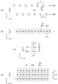
次に、液滴吐出ヘッド20の吐出ノズル24の配列と、それぞれの吐出ノズル24から吐出された液滴の着弾位置と、の関係について、図6を参照して説明する。図6は、吐出ノズルと、それぞれの吐出ノズルから吐出された液滴の着弾位置と、の関係を示す説明図である。図6(a)は、吐出ノズルの配置位置を示す説明図であり、図6(b)は、液滴をノズル列の延在方向に直線状に着弾させた状態を示す説明図であり、図6(c)は、液滴を吐出走査方向に直線状に着弾させた状態を示す説明図であり、図6(d)は、液滴を面状に着弾させた状態を示す説明図である。図6に示したX軸方向及びY軸方向は、ヘッドユニット21が液滴吐出装置1に取り付けられた状態において、図1に示したX軸方向又はY軸方向と一致している。Y軸方向が吐出走査方向であって、図6に示した矢印aの方向に吐出ノズル24(液滴吐出ヘッド20)を相対移動させながら、任意の位置において機能液の液滴を吐出することによって、Y軸方向の任意の位置に液滴を着弾させることができる。
<Landing position>
Next, the relationship between the arrangement of the
図6(a)に示すように、ノズル列24Aを構成する吐出ノズル24は、X軸方向にノズルピッチPの中心間距離で配列されている。上述したように、2列のノズル列24Aをそれぞれ構成する吐出ノズル24同士は、X軸方向において、相互に、ノズルピッチPの1/2ずつ位置がずれている。
As shown in FIG. 6A, the
図6(b)に示すように、着弾位置を示す着弾点91と、着弾した液滴の濡れ広がり状態を示す着弾円91Aとで、着弾した1滴の液滴の状態を示している。2列のノズル列24Aの全部の吐出ノズル24から、図6(b)に二点鎖線で示した仮想線L上に着弾させるタイミングで、それぞれ液滴を吐出させることによって、ノズルピッチPの1/2の中心間間隔で着弾円91Aが連なる直線が形成される。
As shown in FIG. 6 (b), the
図6(c)に示すように、一つの吐出ノズル24から連続して液滴を吐出させることによって、Y軸方向に着弾円91Aが連なる直線が形成される。Y軸方向における着弾点91間の中心間距離の最小値を、最小着弾距離dと表記する。最小着弾距離dは、吐出走査方向の相対移動速度(mm/sec)と、吐出ノズル24の最小吐出間隔(sec)との積である。
As shown in FIG. 6C, by continuously ejecting liquid droplets from one
図6(d)に示すように、二点鎖線で示した仮想線L1,L2,L3上に着弾させるタイミングで、それぞれ液滴を吐出させることによって、ノズルピッチPの1/2の中心間間隔で着弾円91Aが連なる直線が、Y軸方向に並列した着弾面が形成される。図6(d)に示した仮想線L1,L2,L3間の距離が最小着弾距離dの場合のそれぞれの着弾点91が、液滴吐出装置1によって機能液の液滴を配置可能な位置である。
As shown in FIG. 6 (d), by ejecting liquid droplets at the timing of landing on virtual lines L1, L2, and L3 indicated by two-dot chain lines, the center-to-center spacing of 1/2 of the nozzle pitch P is obtained. Thus, a landing surface is formed in which straight lines connecting the landing circles 91A are arranged in parallel in the Y-axis direction. Each
画像の描画に際しては、画像の情報に従って、図6(d)に示したそれぞれの着弾点91の位置について、液滴を配置する位置を定める。例えば、当該配置位置、及び配置位置に液滴を吐出する吐出ノズル24を指定した配置表を形成し、配置表に従って機能液を着弾させることによって、画像の情報によって規定される画像を描画する。なお、図6(d)に示した例では、着弾円91Aの間に隙間が存在するが、ノズルピッチPや最小着弾距離dに対して、吐出する液滴の1滴あたりの吐出重量を適切に定めることによって、隙間なく機能液を配置することが可能である。
At the time of drawing an image, a position where a droplet is arranged is determined for each position of the
<紫外線射出時間>
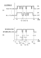
次に、吐出制御信号(吐出指令信号)に基づいて、UVLED96を制御して紫外線を射出させる射出時間について、図7を参照して説明する。図7は、吐出制御信号(吐出指令信号)の発信タイミングと、紫外線を射出させる射出時間とを示すタイミング図である。図7(a)は、ヘッドユニットが備える液滴吐出ヘッドが有する吐出ノズルごとの吐出制御信号(吐出指令信号)の発信タイミングを示すタイミング図であり、図7(b)は、UVLEDを紫外線射出状態にさせる点灯時点、及び紫外線射出停止状態にさせる消灯時点を示すタイミング図である。
<UV emission time>
Next, the injection time for controlling the
上述したように、それぞれの吐出ノズル24は、最小吐出間隔ごとに液滴を吐出することが可能である。吐出ノズル24に液滴の吐出を指令する吐出制御信号が、吐出指令信号である。図6(c)を参照して説明したように、一つの吐出ノズル24から連続して液滴を吐出させる場合には、最小吐出間隔ごとに、吐出指令信号が送られている。図7(a)では、吐出制御信号を、ON状態とOFF状態の2値で示している。ON状態は、吐出指令信号が発信され、最小吐出間隔ごとに、吐出指令信号が発信されている状態である。OFF状態は、吐出指令信号が送られていない状態であって、上述したように、ラッチ信号(LAT)がラッチ回路86に入力されるタイミングでラッチされたノズルデータが「OFF」の場合である。吐出ノズル24がOFF状態であるかは、吐出指令信号が発信されてから最小吐出間隔が経過した時点において、吐出指令信号が発信されないことで、判定できる。この場合の最小吐出間隔が、経過時間に相当する。
As described above, each
図7(a)に示すように、それぞれの吐出ノズル24に機能液の吐出を制御するための吐出制御信号は、画像データによって、「ON」又は「OFF」となる。吐出制御信号が「ON」の場合には、ノズルデータが「ON」の場合、すなわち、吐出指令信号が送られている場合であって、液滴吐出ヘッド20は、吐出指令信号が送られたタイミングで、当該吐出指令信号に対応する吐出ノズル24から機能液を吐出している。
紫外線照射制御部74は、ヘッドユニット21が有する3240個の吐出ノズル24に対する吐出制御信号によって、UVLED96を制御する。しかし、図7に示した例では、説明を簡単にするために、吐出ノズル24n及び吐出ノズル24mの吐出制御信号で代表させて説明する。
As shown in FIG. 7A, the ejection control signal for controlling the ejection of the functional liquid to each
The ultraviolet
図7(b)に示すように、紫外線照射制御部74は、時点T11においてUVLED96を点灯させて、紫外線射出停止状態のUVLED96を、紫外線射出状態にする。時点T11は、時点T1から切替遅延時間t1後の時点である。時点T1は、吐出制御部72から吐出指令信号が送信されることで、OFF状態であった吐出ノズル24mが、ON状態になった時点である。時点T1は、また、吐出走査において、吐出走査開始時点ではヘッドユニット21が有する吐出ノズル24の全てがOFF状態であり、ヘッドユニット21が有する吐出ノズル24の中の少なくとも1個の吐出ノズル24がON状態になった時点である。切替遅延時間t1については、後述する。
As shown in FIG. 7B, the ultraviolet
紫外線照射制御部74は、時点T21においてUVLED96を消灯させて、紫外線射出状態のUVLED96を、紫外線射出停止状態にする。時点T21は、時点T2から切替遅延時間t1後の時点である。時点T2は、先に吐出ノズル24nがON状態からOFF状態になっている状態で、吐出ノズル24mがON状態からOFF状態になった時点である。時点T2は、ヘッドユニット21が有する吐出ノズル24の全てがOFF状態になった時点である。
The ultraviolet
紫外線照射制御部74は、時点T31及び時点T51においてUVLED96を点灯させて、紫外線射出停止状態のUVLED96を、紫外線射出状態にする。時点T31及び時点T51は、時点T3又は時点T5から切替遅延時間t1後の時点である。時点T3及び時点T5は、OFF状態であった吐出ノズル24n又は吐出ノズル24mがON状態になった時点である。時点T3及び時点T5は、吐出走査において、ヘッドユニット21が有する吐出ノズル24の全てがOFF状態である状態から、ヘッドユニット21が有する吐出ノズル24の中の少なくとも1個の吐出ノズル24がON状態になった時点である。
The ultraviolet
紫外線照射制御部74は、時点T41及び時点T61においてUVLED96を消灯させて、紫外線射出状態のUVLED96を、紫外線射出停止状態にする。時点T41及び時点T61は、時点T4又は時点T6から切替遅延時間t1後の時点である。時点T4及び時点T6は、先に吐出ノズル24mがON状態からOFF状態になっている状態で、吐出ノズル24nがON状態からOFF状態になった時点である。時点T4及び時点T6は、ヘッドユニット21が有する吐出ノズル24の全てがOFF状態になった時点である。
時点T11から時点T21の間、時点T31から時点T41の間、及び時点T51から時点T61の間が、UVLED96に紫外線を射出させる射出時間である。
The ultraviolet
The time between the time T11 and the time T21, the time between the time T31 and the time T41, and the time between the time T51 and the time T61 are emission times for the
<ヘッド対向領域及び照射部対向領域>
次に、ヘッド対向領域及び照射部対向領域について、図8を参照して説明する。図8は、ヘッド対向領域(着弾対象領域)と、照射部対向領域(UV光照射領域)との位置関係を、キャリッジユニットと対比して示す説明図である。図8(a)は、キャリッジユニットをX軸方向に平行な方向から見た側面形状、及びキャリッジユニットと被描画媒体との位置関係を示す説明図であり、図8(b)は、被描画媒体上のヘッド対向領域と、照射部対向領域との位置関係を示す説明図であり、図8(c)は、1回の吐出走査における着弾対象領域の始端及び終端と、UV光照射領域の始端及び終端との位置関係を示す説明図である。図8に示したX軸方向、Y軸方向、及びZ軸方向は、キャリッジユニット22が液滴吐出装置1に取り付けられた状態において、図1に示したX軸方向、Y軸方向、又はZ軸方向と一致している。
<Head facing area and irradiation part facing area>
Next, the head facing region and the irradiation unit facing region will be described with reference to FIG. FIG. 8 is an explanatory diagram showing the positional relationship between the head facing region (landing target region) and the irradiation unit facing region (UV light irradiation region) in comparison with the carriage unit. FIG. 8A is an explanatory diagram showing a side shape of the carriage unit viewed from a direction parallel to the X-axis direction, and the positional relationship between the carriage unit and the drawing medium, and FIG. FIG. 8C is a diagram illustrating the positional relationship between the head facing area and the irradiation section facing area on the medium, and FIG. 8C illustrates the start and end of the landing target area and the UV light irradiation area in one ejection scan. It is explanatory drawing which shows the positional relationship with a start end and a termination | terminus. The X-axis direction, Y-axis direction, and Z-axis direction shown in FIG. 8 are the X-axis direction, Y-axis direction, or Z-axis shown in FIG. 1 when the
図8(a)に示したように、キャリッジユニット22が備えるヘッドユニット21と、2個の紫外線照射部95とが、並んで被描画媒体100に対向している。
図8(b)に示すように、被描画媒体100におけるヘッドユニット21が対向する領域をヘッド対向領域120と表記し、紫外線照射部95が対向する領域を、照射部対向領域190と表記する。
ヘッド対向領域120は、媒体載置台31に支持された被描画媒体100における、ヘッドユニット21が備える9個の液滴吐出ヘッド20が対向する範囲を、長方形で表した領域である。ユニットノズル列240Aから吐出されて着弾した機能液は、X軸方向において、ヘッド対向領域120の幅の範囲に位置している。照射部対向領域190は、媒体載置台31に支持された被描画媒体100における、紫外線照射部95によって同時に紫外線を照射可能な領域である。
As shown in FIG. 8A, the
As shown in FIG. 8B, a region of the drawing medium 100 facing the
The
図8(c)に示すように、キャリッジユニット22が走査されて、ヘッド対向領域120がY軸方向に走査された軌跡の領域を着弾対象領域220と表記する。照射部対向領域190がY軸方向に走査された軌跡の領域をUV光照射領域290と表記する。ヘッドユニット21の両側にそれぞれ配設された紫外線照射部95のうち、吐出走査に際して、稼働させられる紫外線照射部95は、ヘッドユニット21に対して進行方向の後側の紫外線照射部95である。走査方向が図8(a)に矢印c1で示した方向の場合、矢印c1の後側の紫外線照射部95が、稼働させられる。
As shown in FIG. 8C, a region of a locus in which the
ヘッドユニット21の液滴吐出ヘッド20は、時点T1から時点T2の間に吐出を実施して、着弾領域始端221から着弾領域終端222の間の着弾対象領域220aに、機能液の液滴を着弾させる。着弾させた機能液によって、着弾対象領域220a内に、画像40を構成する画像体40aを形成する。
さらに、ヘッドユニット21の液滴吐出ヘッド20は、時点T3から時点T4の間、及び時点T5から時点T6の間に吐出を実施して、着弾領域始端223から着弾領域終端224の間の着弾対象領域220b、及び着弾領域始端225から着弾領域終端226の間の着弾対象領域220cに機能液の液滴を着弾させる。着弾させた機能液によって、着弾対象領域220b内に、画像40を構成する画像体40bを形成し、着弾対象領域220c内に、画像40を構成する画像体40cを形成する。時点T1、時点T2、時点T3、時点T4、時点T5、及び時点T6は、図7を参照して説明した時点T1、時点T2、時点T3、時点T4、時点T5、又は時点T6である。
The
Further, the
矢印c1の後側の紫外線照射部95は、時点T11から時点T21の間に紫外線を射出して、照射領域始端291から照射領域終端292の間のUV光照射領域290aに、紫外線を照射する。
さらに、矢印c1の後側の紫外線照射部95は、時点T31から時点T41の間に紫外線を射出して、照射領域始端293から照射領域終端294の間のUV光照射領域290bに、紫外線を照射し、時点T51から時点T61の間に紫外線を射出して、照射領域始端295から照射領域終端296の間のUV光照射領域290cに、紫外線を照射する。時点T11、時点T21、時点T31、時点T41、時点T51、及び時点T61は、図7を参照して説明した時点T11、時点T21、時点T31、時点T41、時点T51、又は時点T61である。
The
Further, the
被描画媒体100の1点には、ヘッドユニット21が有する吐出ノズル24のいずれかが適切な吐出位置に位置した時点において、当該吐出ノズル24から液滴を吐出することで、機能液を着弾させる。上述した例では、ヘッドユニット21が有する吐出ノズル24は、3240個である。1個のヘッド対向領域120の範囲では、図3を参照して説明した吐出ノズル24の位置に対応する、被描画媒体100の3240点に、機能液を着弾させることができる。
When one of the
着弾対象領域220の全面に機能液の液滴を着弾させるためには、ヘッド対向領域120を最小着弾距離dの間隔で連ねて、それぞれのヘッド対向領域120において、ヘッドユニット21が有する全ての吐出ノズル24から吐出を実施させる。時点T1、時点T3、及び時点T5において、吐出ノズル24からの吐出を開始させる場合、時点T1、時点T3、及び時点T5は、ヘッド対向領域120の走査方向の先端が、着弾領域始端221、着弾領域始端223、又は着弾領域始端225に一致する時点から、吐出ノズル24の最小吐出間隔(sec)の1/2が経過した時点である。時点T1、時点T3、又は時点T5において、吐出ノズル24から吐出を実施させることで、着弾領域始端221、着弾領域始端223、又は着弾領域始端225を形成する位置に機能液の液滴を着弾させる。
In order to land the liquid droplets of the functional liquid on the entire
時点T2、時点T4、及び時点T6において、吐出ノズル24からの吐出を停止させる場合、時点T2、時点T4、及び時点T6は、ヘッド対向領域120の走査方向の後端が、着弾領域終端222、着弾領域終端224、又は着弾領域終端226に一致する時点である。時点T2、時点T4、又は時点T6において、吐出ノズル24からの吐出を実施させないことで、着弾対象領域220a、着弾対象領域220b、又は着弾対象領域220cから外れた位置には、機能液の液滴を着弾させない。
When the ejection from the
被描画媒体100の1点には、紫外線照射部95が対向しており、照射部対向領域190に位置している間に紫外線が照射される。当該照射時間とUVLED96から射出される紫外線の強度との積が、照射される光量であり、充分な光量を照射するためには、当該照射時間が必要である。時点T11、時点T31、及び時点T51は、照射部対向領域190の走査方向の先端が、照射領域始端291、照射領域始端293、又は照射領域始端295に一致する時点である。時点T21、時点T41、及び時点T61は、照射部対向領域190の走査方向の後端が、照射領域終端292、照射領域終端294、又は照射領域終端296に一致する時点である。
UV光照射領域290a、UV光照射領域290b、及びUV光照射領域290cには、上記した時点においてUVLED96を点灯及び消灯させることで、着弾させられた機能液を適切な硬化率に硬化させることができる光量の紫外線が照射される。UV光照射領域290a、UV光照射領域290b、及びUV光照射領域290cのY軸方向(吐出走査方向)の前後には、着弾させられた機能液を適切な硬化率に硬化させることができる光量には満たない光量の紫外線が照射される領域が存在する。
The
In the UV
ヘッド対向領域120と照射部対向領域190とは、吐出走査方向(Y軸方向)においてずれている。このため、ヘッドユニット21によって吐出を実施する時点と同じ時点において、紫外線照射部95による紫外線の照射を実施すると、UV光照射領域290における、着弾対象領域220を外れた部分が発生する。時点T1、時点T3、及び時点T5に対して時点T11、時点T31、又は時点T51を、切替遅延時間t1だけ遅延させることによって、照射領域始端291、照射領域始端293、及び照射領域始端295と、着弾領域始端221、着弾領域始端223、又は着弾領域始端225との距離を小さくしている。切替遅延時間t1が、第一遅延時間に相当する。切替遅延時間t1は、キャリッジユニット22におけるそれぞれの紫外線照射部95の位置や走査速度などにより設定される。
The
また、ヘッドユニット21による吐出を停止する時点と同じ時点において、紫外線照射部95による紫外線の照射を停止すると、着弾対象領域220において、UV光照射領域290から外れる部分が発生する可能性がある。時点T2、時点T4、及び時点T6に対して時点T21、時点T41、又は時点T61を、切替遅延時間t1だけ遅延させることによって、照射領域終端292、照射領域終端294、及び照射領域終端296の位置を、着弾領域終端222、着弾領域終端224、又は着弾領域終端226より、吐出走査方向の進行方向側に位置させている。
これにより、UV光照射領域290a、UV光照射領域290b、及びUV光照射領域290cは、着弾対象領域220a、着弾対象領域220b、又は着弾対象領域220cを含む範囲になっている。
Further, if the irradiation of ultraviolet rays by the
Thereby, the UV
<紫外線射出時間の他の例1>
次に、紫外線を照射する領域が、上述したUV光照射領域290とは異なるUV光照射領域390となる、紫外線射出時間の例について、図9を参照して説明する。図9は、吐出指令信号の発信タイミングと、紫外線を射出させる射出時間とを示すタイミング図、及びヘッド対向領域(着弾対象領域)と、照射部対向領域(UV光照射領域)との位置関係を示す説明図である。図9(a)は、ヘッドユニットが備える液滴吐出ヘッドが有する吐出ノズルごとの吐出指令信号の発信タイミングを示すタイミング図であり、図9(b)は、UVLEDを紫外線射出状態にさせる点灯時点、及び紫外線射出停止状態にさせる消灯時点を示すタイミング図であり、図9(c)は、ヘッド対向領域(着弾対象領域)と、照射部対向領域(UV光照射領域)との位置関係を示す説明図である。図9(c)に示したX軸方向、及びY軸方向は、キャリッジユニット22が液滴吐出装置1に取り付けられた状態において、図1に示したX軸方向、又はY軸方向と一致している。
<Other example 1 of ultraviolet emission time>
Next, an example of the ultraviolet emission time in which the region irradiated with ultraviolet rays is a UV
図9(a)に示した、ヘッドユニット21が備える液滴吐出ヘッド20が有する吐出ノズル24ごとの吐出指令信号の発信タイミングは、図7(a)を参照して説明した吐出指令信号の発信タイミングと同様である。
The transmission timing of the discharge command signal for each
図9(b)に示すように、紫外線照射制御部74は、時点T11においてUVLED96を点灯させて、紫外線射出停止状態のUVLED96を、紫外線射出状態にする。時点T11は、図7(a)を参照して説明した時点T11であって、時点T1から切替遅延時間t1後の時点である。時点T1は、OFF状態であった吐出ノズル24mがON状態になった時点である。時点T1は、また、吐出走査において、吐出走査開始時点ではヘッドユニット21が有する吐出ノズル24の全てがOFF状態であり、ヘッドユニット21が有する吐出ノズル24の中の少なくとも1個の吐出ノズル24がON状態になった時点である。切替遅延時間t1は、図8を参照して説明した切替遅延時間t1である。
As shown in FIG. 9B, the ultraviolet
紫外線照射制御部74は、時点T2、時点T4、及び時点T6においてヘッドユニット21が有する吐出ノズル24の全てがOFF状態になったことに対応して、時点T22、時点T42、及び時点T62においてUVLED96を消灯させて、紫外線射出状態のUVLED96を、紫外線射出停止状態にする。時点T22、時点T42、及び時点T62は、時点T2、時点T4、又は時点T6から消灯遅延時間t2後の時点である。消灯遅延時間t2は、切替遅延時間t1より長い時間である。
The UV
ここで、時点T22は、時点T2から消灯遅延時間t2を経過することで、時点T3を過ぎている。時点T3は、ヘッドユニット21が有する吐出ノズル24の中の少なくとも1個の吐出ノズル24がON状態になった時点である。紫外線照射制御部74は、時点T3から、吐出ノズル24がON状態であることに対応して、UVLED96を紫外線射出状態のまま維持する。したがって、時点T22におけるUVLED96の消灯は、実行されない。同様に、時点T42は、時点T4から消灯遅延時間t2を経過することで、時点T5を過ぎている。時点T42におけるUVLED96の消灯も、実行されない。
時点T62におけるUVLED96の消灯は、実行される。
Here, the time point T22 is past the time point T3 because the turn-off delay time t2 has elapsed from the time point T2. Time T3 is a time when at least one of the
The
図9(c)に示したように、紫外線照射制御部74は、時点T11から時点T62の間に、UVLED96に紫外線を射出させて、照射領域始端391から照射領域終端392の間のUV光照射領域390に、紫外線を照射させる。時点T2、及び時点T4においてヘッドユニット21が有する吐出ノズル24の全てがOFF状態になったことに対応する、UVLED96の消灯が実行されないため、UV光照射領域390は、連続した領域である。これにより、UV光照射領域390は、着弾対象領域220a、着弾対象領域220b、及び着弾対象領域220cを含む範囲になっている。
As shown in FIG. 9C, the ultraviolet
図8を参照して説明したUV光照射領域290a、UV光照射領域290b、及びUV光照射領域290cに紫外線を照射する際には、時点T2、時点T4、及び時点T6に対して時点T21、時点T41、又は時点T61を、切替遅延時間t1だけ遅延させていた。これにより、照射領域終端292、照射領域終端294、及び照射領域終端296の位置を、着弾領域終端222、着弾領域終端224、又は着弾領域終端226より、吐出走査方向の進行方向側に位置させていた。
時点T62は、時点T6から切替遅延時間t1より長い消灯遅延時間t2後の時点であるため、照射領域終端392を確実に、着弾領域終端226より、吐出走査方向の進行方向側に位置させることができる。消灯遅延時間t2が、第二遅延時間に相当する。切替遅延時間t1が、第一遅延時間に相当する。
When the UV
Since the time point T62 is a time point after the turn-off delay time t2 longer than the switching delay time t1 from the time point T6, the
<紫外線射出時間の他の例2>
次に、紫外線を照射する領域が、上述したUV光照射領域290及びUV光照射領域390とは異なるUV光照射領域490となる、紫外線射出時間の例について、図10を参照して説明する。図10は、吐出指令信号の発信タイミングと、紫外線を射出させる射出時間とを示すタイミング図、及びヘッド対向領域(着弾対象領域)と、照射部対向領域(UV光照射領域)との位置関係を示す説明図である。図10(a)は、ヘッドユニットが備える液滴吐出ヘッドが有する吐出ノズルごとの吐出指令信号の発信タイミングを示すタイミング図であり、図10(b)は、UVLEDを紫外線射出状態にさせる点灯時点、及び紫外線射出停止状態にさせる消灯時点を示すタイミング図であり、図10(c)は、ヘッド対向領域(着弾対象領域)と、照射部対向領域(UV光照射領域)との位置関係を示す説明図である。図10(c)に示したX軸方向、及びY軸方向は、キャリッジユニット22が液滴吐出装置1に取り付けられた状態において、図1に示したX軸方向、又はY軸方向と一致している。
<Other example 2 of ultraviolet emission time>
Next, an example of an ultraviolet emission time in which a region irradiated with ultraviolet light is a UV
図10(a)に示した、ヘッドユニット21が備える液滴吐出ヘッド20が有する吐出ノズル24ごとの吐出指令信号の発信タイミングは、図7(a)を参照して説明した吐出指令信号の発信タイミングと同様である。
The discharge command signal transmission timing for each
図10(b)に示すように、紫外線照射制御部74は、時点T1においてUVLED96を点灯させて、紫外線射出停止状態のUVLED96を、紫外線射出状態にする。上述したように、時点T1は、OFF状態であった吐出ノズル24mがON状態になった時点である。時点T1は、また、吐出走査において、吐出走査開始時点ではヘッドユニット21が有する吐出ノズル24の全てがOFF状態であり、ヘッドユニット21が有する吐出ノズル24の中の少なくとも1個の吐出ノズル24がON状態になった時点である。
As shown in FIG. 10B, the ultraviolet
紫外線照射制御部74は、時点T1から、設定射出時間t3後の時点T63において、UVLED96を消灯させる。
図10(c)に示したように、紫外線照射制御部74は、時点T1から時点T63の間に、UVLED96に紫外線を射出させて、照射領域始端491から照射領域終端492の間のUV光照射領域490に、紫外線を照射させる。時点T1から、設定射出時間t3の間、UVLED96は紫外線射出状態であるため、UV光照射領域490は、連続した領域である。
時点T63は、照射部対向領域190の走査方向における後端が、着弾領域終端226より、吐出走査方向の進行方向側に位置した時点である。これにより、UV光照射領域490は、着弾対象領域220a、着弾対象領域220b、及び着弾対象領域220cを含む範囲になっている。
The ultraviolet
As shown in FIG. 10C, the ultraviolet
A time point T63 is a time point when the rear end of the irradiation
以下、実施形態による効果を記載する。本実施形態によれば、以下の効果が得られる。
(1)紫外線照射制御部74は、吐出制御部72が吐出ノズル24からの機能液の吐出を制御するために液滴吐出ヘッド20に送信する吐出制御信号と同じ吐出制御信号に従って、UVLED96を制御して紫外線を射出させる。
UVLED96は、液滴吐出ヘッド20から吐出されて被描画媒体上に着弾した機能液に紫外線を照射するために、紫外線を射出させられる。したがって、UVLED96を射出状態にする必要が発生するのは、液滴吐出ヘッド20の吐出ノズル24から被描画媒体に向けて機能液が吐出された場合である。
吐出ノズル24からの機能液の吐出を制御するために発信される吐出制御信号に基づいて、UVLED96を制御して紫外線を射出させることで、必要な場合に合わせて、適切に、UVLED96に紫外線を射出させることができる。また、紫外線を射出させることが不要な場合であるにもかかわらず、UVLED96に紫外線を射出させることを抑制することができる。
Hereinafter, the effect by embodiment is described. According to the present embodiment, the following effects can be obtained.
(1) The ultraviolet
The
Based on the discharge control signal transmitted to control the discharge of the functional liquid from the
(2)紫外線照射制御部74は、吐出制御部72から吐出指令信号が送信されることによって、UVLED96に紫外線を射出させる。UVLED96を射出状態にする必要が発生するのは、液滴吐出ヘッド20の吐出ノズル24から被描画媒体に向けて機能液が吐出された場合である。吐出指令信号によってUVLED96に紫外線を射出させることで、必要な場合に合わせて、適切に、UVLED96に紫外線を射出させることができる。
(2) The ultraviolet
(3)紫外線照射制御部74は、吐出制御部72から吐出指令信号が送信されていない場合に、UVLED96を消灯させて紫外線射出停止状態にする。これにより、吐出走査を実施している時間の全てにおいてUVLED96を紫外線射出状態にさせる場合にくらべて、紫外線射出状態にさせることが不必要な場合においてUVLED96を紫外線射出状態にさせることを抑制することができる。
(3) When the discharge command signal is not transmitted from the
(4)紫外線を照射する領域がUV光照射領域290又はUV光照射領域390となる紫外線射出時間は、時点T1から切替遅延時間t1後の、時点T11において、UVLED96を点灯させることで、開始する。時点T1は、ヘッド対向領域120の走査方向の先端が、着弾領域始端221に一致する時点から、吐出ノズル24の最小吐出間隔(sec)後の時点である。時点T11は、照射部対向領域190の走査方向の先端が、照射領域始端291に一致する時点である。
時点T11を、時点T1から切替遅延時間t1だけ遅らせることで、ヘッド対向領域120の先端と、照射部対向領域190の先端との距離にくらべて、照射領域始端291又は照射領域始端391と、着弾領域始端221との距離を小さくすることができる。すなわち、着弾対象領域220に含まれない領域に紫外線を照射することを抑制することができる。
(4) The ultraviolet emission time in which the ultraviolet irradiation region becomes the UV
By delaying the time point T11 from the time point T1 by the switching delay time t1, the irradiation region start end 291 or the irradiation region start end 391 and the landing are compared with the distance between the tip of the
(5)紫外線を照射する領域がUV光照射領域390となる紫外線射出時間は、時点T11において、UVLED96を点灯させることで開始し、時点T62でUVLED96を消灯させることで終了する。時点T62は、時点T6から消灯遅延時間t2後の時点である。UVLED96の紫外線射出状態が終了する時点を消灯遅延時間t2だけ遅らせることで、照射領域終端392を確実に、着弾領域終端226より、吐出走査方向の進行方向側に位置させることができる。すなわち、着弾対象領域220の着弾領域終端226側に紫外線が照射されない部分が生ずることを抑制することができる。
(5) The ultraviolet emission time when the region irradiated with ultraviolet rays becomes the UV
(6)紫外線を照射する領域がUV光照射領域390となる紫外線射出時間は、時点T11において、UVLED96を点灯させることで開始し、時点T22及び時点T42でUVLED96を消灯させることで中断する。時点T2又は時点T4において、吐出制御部72から吐出指令信号が送信されていない状態になったことに対応して、時点T22及び時点T42において、UVLED96を消灯させる。時点T22及び時点T42は、時点T2又は時点T4から消灯遅延時間t2後の時点である。
しかし、消灯遅延時間t2の間に、時点T3又は時点T5において、吐出指令信号が送信されるため、時点T3より遅い時点T22、及び時点T5より遅い時点T42におけるUVLED96の消灯は実行されない。こすなわち、UVLED96を、時点T21又は時点T41で消灯させ、時点T3又は時点T5で点灯させる操作が省略されている。これにより、短い時間の間にUVLED96を消灯させたり点灯させたりすることを抑制することができる。
(6) The ultraviolet emission time in which the ultraviolet irradiation region becomes the UV
However, since the discharge command signal is transmitted at the time T3 or the time T5 during the turn-off delay time t2, the
(7)紫外線を照射する領域がUV光照射領域490となる紫外線射出時間は、時点T1において、UVLED96を点灯させることで開始している。時点T1は、ヘッド対向領域120の走査方向の先端が、着弾領域始端221に一致する時点から、吐出ノズル24の最小吐出間隔(sec)後の時点である。
時点T1において、UVLED96を点灯させることで、照射領域始端491と、着弾領域始端221との距離を、ヘッド対向領域120の先端と、照射部対向領域190の先端との距離と略同じにすることができる。これにより、着弾対象領域220aの着弾領域始端221側の端に、充分な紫外線が照射されない領域が発生することを抑制することができる。
(7) The ultraviolet emission time in which the ultraviolet irradiation region becomes the UV
At time T1, the
(8)紫外線を照射する領域がUV光照射領域490となる紫外線射出時間は、時点T1において、UVLED96を点灯させることで開始し、時点T1から、設定射出時間t3後の時点T63において、UVLED96を消灯させることで終了している。
設定射出時間t3を適切な長さに設定することで、照射領域終端492の位置を、確実に着弾領域終端226より吐出走査方向の進行側にすることができる。すなわち、着弾対象領域220の着弾領域終端226側に紫外線が照射されない部分が生ずることを抑制することができる。また、照射領域終端492の位置を、着弾領域終端226の位置に近づけることができる。すなわち、着弾対象領域220に含まれない領域に紫外線を照射することを抑制することができる。
(8) The ultraviolet ray emission time when the ultraviolet ray irradiation region becomes the UV
By setting the set ejection time t3 to an appropriate length, the position of the
以上、添付図面を参照しながら好適な実施形態について説明したが、好適な実施形態は、前記実施形態に限らない。実施形態は、要旨を逸脱しない範囲内において種々変更を加え得ることは勿論であり、以下のように実施することもできる。 As mentioned above, although preferred embodiment was described referring an accompanying drawing, suitable embodiment is not restricted to the said embodiment. The embodiment can of course be modified in various ways without departing from the scope, and can also be implemented as follows.
(変形例1)前記実施形態においては、紫外線を照射する領域がUV光照射領域390となる紫外線射出時間は、時点T11において、UVLED96を点灯させることで開始し、時点T22、時点T42、及び時点T62でUVLED96を消灯させる設定であった。時点T22、時点T42、及び時点T62は、時点T2、時点T4、又は時点T6から、消灯遅延時間t2後の時点であった。しかし、硬化光照射手段を射出停止状態する時点を、吐出指令信号が発信された時点から経過時間を経過した時点から、一律に第二遅延時間を経過した時点にすることは必須ではない。例えば、時点T62が相当する、紫外線射出時間を終了する際の消灯時点のみ、吐出指令信号が発信された時点から経過時間を経過した時点から第二遅延時間だけ遅らせてもよい。
(Modification 1) In the above-described embodiment, the UV emission time when the UV irradiation region becomes the UV
(変形例2)前記実施形態においては、紫外線を照射する領域がUV光照射領域490となる紫外線照射時間は、吐出が開始される時点T1において、UVLED96を点灯させることで開始し、時点T1から、設定射出時間t3後の時点T63において、UVLED96を消灯させることで終了している。しかし、設定射出時間が経過した時点において、硬化光照射手段を射出停止状態にする場合に、硬化光照射手段を射出状態にする時点が、時点T1が相当する吐出指令信号が発信された時点であることは必須ではない。吐出指令信号が発信された時点から第一遅延時間だけ遅らせた時点で硬化光照射手段を射出状態にして、設定射出時間が経過した時点において、硬化光照射手段を射出停止状態にしてもよい。
(Modification 2) In the above-described embodiment, the ultraviolet irradiation time in which the ultraviolet irradiation region becomes the UV
(変形例3)前記実施形態においては、紫外線を照射する領域がUV光照射領域390となる紫外線射出時間は、時点T11において、UVLED96を点灯させることで開始し、時点T22、時点T42、及び時点T62でUVLED96を消灯させる設定であった。時点T22、時点T42、及び時点T62は、時点T2、時点T4、又は時点T6から、消灯遅延時間t2後の時点であった。しかし、吐出指令信号が発信された時点から経過時間を経過した時点からさらに第二遅延時間を経過した時点に、硬化光照射手段を射出停止状態にする場合に、硬化光照射手段を射出状態にする時点が、吐出指令信号が発信された時点から第一遅延時間だけ遅らせた時点であることは必須ではない。時点T1が相当する吐出指令信号が発信された時点において硬化光照射手段を射出状態にして、吐出指令信号が発信された時点から経過時間を経過した時点からさらに第二遅延時間を経過した時点に、硬化光照射手段を射出停止状態にしてもよい。
(Modification 3) In the above-described embodiment, the ultraviolet emission time when the region irradiated with ultraviolet rays becomes the UV
(変形例4)前記実施形態においては、紫外線を照射する領域がUV光照射領域290となる紫外線射出時間は、時点T11において、UVLED96を点灯させることで開始し、時点T31及び時点51でもUVLED96を点灯させ、時点T21、時点T41、及び時点T61でUVLED96を消灯させる設定であった。時点T21、時点T41、及び時点T61は、時点T2、時点T4、又は時点T6から、切替遅延時間t1後の時点であった。しかし、吐出指令信号が発信された時点から経過時間を経過した時点からさらに遅延時間を経過した時点に、硬化光照射手段を射出停止状態にする場合に、硬化光照射手段を射出状態にする時点が、吐出指令信号が発信された時点から第一遅延時間だけ遅らせた時点であることは必須ではない。時点T1が相当する吐出指令信号が発信された時点において硬化光照射手段を射出状態にして、吐出指令信号が発信された時点から切替遅延時間t1を経過した時点に、硬化光照射手段を射出停止状態にしてもよい。
(Modification 4) In the above-described embodiment, the UV emission time when the UV irradiation region becomes the UV
(変形例5)前記実施形態においては、紫外線を照射する領域がUV光照射領域290となる紫外線射出時間は、時点T11において、UVLED96を点灯させることで開始し、時点T31及び時点51でもUVLED96を点灯させ、時点T21、時点T41、及び時点T61でUVLED96を消灯させる設定であった。時点T11、時点T31、及び時点T51は、時点T1、時点T3、又は時点T5から、切替遅延時間t1後の時点であった。時点T21、時点T41、及び時点T61も、時点T2、時点T4、又は時点T6から、切替遅延時間t1後の時点であった。しかし、硬化光照射手段を射出状態にする時点が、吐出指令信号が発信された時点から第一遅延時間だけ遅らせた時点であり、吐出指令信号が発信された時点から経過時間を経過した時点からさらに遅延時間を経過した時点に、硬化光照射手段を射出停止状態にする場合に、当該遅延時間が第一遅延時間と同じ時間であることは必須ではない。当該遅延時間と第一遅延時間とは、長さが異なる時間に設定してもよい。
(Modification 5) In the above-described embodiment, the UV emission time when the UV irradiation region becomes the UV
(変形例6)前記実施形態においては、被描画媒体100の具体例は特に例示しなかったが、被描画媒体としては、膜を形成することによって画像を形成するような製品や、フィルター膜のような機能膜を形成することが必要な製品が挙げられる。
(Modification 6) In the above embodiment, a specific example of the drawing
(変形例7)前記実施形態においては、吐出走査において、キャリッジ走査機構62によってキャリッジユニット22をY軸方向に走査させることによって、液滴吐出ヘッド20及びUVLED96と、被描画媒体100(媒体載置台31)と、を相対移動させていた。しかし、吐出ヘッド及び硬化光射出手段と媒体保持手段とを吐出走査方向に相対移動させる相対走査手段が吐出ヘッド及び硬化光照射手段を走査させる手段であることは必須ではない。相対走査手段は、被描画媒体を保持する媒体保持手段を走査させる手段であってもよい。
(Modification 7) In the above embodiment, in the ejection scanning, the
(変形例8)前記実施形態においては、液滴吐出装置1は、ヘッドユニット21を備えており、ヘッドユニット21が備える液滴吐出ヘッド20が吐出する機能液は単一の機能液であった。しかし、ヘッドユニットが備える吐出ヘッドが吐出する液状体が同一であることは必須ではない。描画装置においては、色が異なるなど、複数種類の異なる液状体を吐出してもよい。色が異なる複数種類の液状体を吐出することでカラー描画も可能である。液状体の種類は、液滴吐出装置が複数のヘッドユニットを備えて、ヘッドユニットごとに異ならせてもよいし、ヘッド組ごとに異ならせてもよいし、液滴吐出ヘッドごとに異ならせてもよいし、ノズル列ごとに異ならせてもよい。吐出ノズルごとに液状体を個別に供給できる液滴吐出ヘッドを用いて、吐出ノズルごとに異なる液状体を吐出してもよい。なお、カラー描画を実施する際には、同じ着弾位置に、複数の、例えば色が異なる液状体を着弾させることができる構成のヘッドユニット又は液滴吐出ヘッドを用いたり、走査方法を用いたりすることで、より微細な描画が可能となる。
(Modification 8) In the embodiment described above, the
(変形例9)前記実施形態においては、液滴吐出装置1は、ヘッドユニット21を1個備えていた。しかし、描画装置が備えるヘッドユニットが1個であることは必須ではない。描画装置が備えるヘッドユニットは、いくつであってもよい。
(Modification 9) In the above embodiment, the
(変形例10)前記実施形態においては、ヘッドユニット21は、液滴吐出ヘッド20を9個備えていたが、ヘッドユニットが備える吐出ヘッドが9個であることは必須ではない。ヘッドユニットが備える吐出ヘッドは、いくつであってもよい。
(Modification 10) In the above embodiment, the
(変形例11)前記実施形態においては、液滴吐出ヘッド20は、多数の吐出ノズル24が略一直線状に並んだノズル列24Aを2列備えていたが、吐出ヘッドが備えるノズル列は何列であってもよい。また、液滴吐出ヘッド20が備える吐出ノズル24は、ノズル列24Aの延在方向において互いの位置がずれていたが、吐出ヘッドは、ノズル列の延在方向において、略同一位置に位置する吐出ノズルを複数備える構成であってもよい。
(Modification 11) In the embodiment described above, the
(変形例12)前記実施形態においては、UVLED96は、紫外線を射出するLEDであった。しかし、硬化光射出手段がLEDであることは必須ではない。硬化光射出手段は、メタルハライドランプのようなランプなどであってもよい。
(Modification 12) In the embodiment, the
(変形例13)前記実施形態においては、ノズル列24Aにおけるノズルピッチは140μmであり、2本のノズル列24Aを備える液滴吐出ヘッド20におけるノズル列方向の吐出ピッチは約70μmであった。しかし、液滴吐出ヘッドにおけるノズルの配置は、液滴吐出ヘッド20における配置に限らない。ノズル列におけるノズルピッチは140μmとは異なるノズルピッチであってもよい。
(Modification 13) In the above embodiment, the nozzle pitch in the
(変形例14)前記実施形態においては、液滴吐出ヘッド20が吐出する機能液は、紫外線硬化型の機能液であり、紫外線照射部95は、紫外線を射出するUVLED96を備えていた。しかし、上述した実施形態において説明した液滴吐出装置で用いる液状体が紫外線硬化型の液状体であることは必須ではない。熱硬化型の液状体など、他の硬化光を用いて処理することによって硬化させる液状体であってもよい。
(Modification 14) In the above embodiment, the functional liquid discharged from the
(変形例15)前記実施形態においては、吐出制御信号に基づいて、吐出ノズルがOFF状態になったことを検出した場合や、硬化光照射手段を射出状態にしてから、所定の設定射出時間が経過した時点で、硬化光照射手段を射出停止状態にしていた。硬化光照射手段を射出停止状態にするのは、他の事象に基づいて実施してもよい。例えば、1回の吐出走査が終了した時点で、硬化光照射手段を射出停止状態にしてもよい。 (Modification 15) In the embodiment described above, when it is detected that the discharge nozzle is turned off based on the discharge control signal, or when the curing light irradiation means is in the injection state, a predetermined injection time is set. At the point of time, the curing light irradiation means was in the injection stopped state. The curing light irradiation unit may be stopped based on other events. For example, the curing light irradiation unit may be in an injection stop state when one ejection scan is completed.
1…液滴吐出装置、2…ヘッド機構部、3…媒体機構部、7…吐出装置制御部、20…液滴吐出ヘッド、20d…ヘッドドライバー、24…吐出ノズル、24A…ノズル列、24m,24n…吐出ノズル、33…媒体移動機構、40…画像、40a,40b,40c…画像体、62…キャリッジ走査機構、65…キャリッジ枠、71…データ処理部、72…吐出制御部、73…キャリッジ走査制御部、74…紫外線照射制御部、91…着弾点、91A…着弾円、95…紫外線照射部、96…UVLED、100…被描画媒体、120…ヘッド対向領域、190…照射部対向領域、220,220a,220b,220c…着弾対象領域、221,223,225…着弾領域始端、222,224,226…着弾領域終端、240A…ユニットノズル列、290,290a,290b,290c…UV光照射領域、291,293,295…照射領域始端、292,294,296…照射領域終端、390…UV光照射領域、391…照射領域始端、392…照射領域終端、490…UV光照射領域、491…照射領域始端、492…照射領域終端。
DESCRIPTION OF
Claims (8)
前記液状体の液滴を吐出する複数の吐出ノズルを備え、前記複数の吐出ノズルのそれぞれの吐出ノズルから、前記媒体保持手段に保持された前記被描画媒体に向けて、前記液状体の前記液滴を吐出する吐出ヘッドと、
前記液状体の硬化を促進する硬化光を、前記媒体保持手段に保持された前記被描画媒体に向けて射出して、前記被描画媒体に前記硬化光を照射する硬化光照射手段と、
前記吐出ヘッドと、前記硬化光照射手段と、を保持するヘッド保持手段と、
前記被描画媒体と前記吐出ヘッドとを相対移動させるとともに、前記吐出ヘッドから前記液状体を吐出して前記被描画媒体に着弾させる吐出走査における、前記吐出ヘッドと前記被描画媒体との相対移動方向である吐出走査方向に、前記ヘッド保持手段と前記媒体保持手段とを相対移動させる相対走査手段と、
前記吐出ヘッドを制御して前記液状体を吐出させる吐出制御手段と、
前記硬化光照射手段を制御して前記硬化光を照射させる硬化光照射制御手段と、を備え、
前記硬化光照射制御手段は、前記吐出制御手段が前記吐出ヘッドからの前記液状体の吐出を制御するために発信する吐出制御信号に基づいて、前記硬化光照射手段を制御して、前記硬化光照射手段を、前記硬化光を射出する射出状態、又は前記硬化光を射出しない射出停止状態にすることを特徴とするインクジェット描画装置。 Medium holding means for holding a drawing medium which is an object to be drawn by placing a photocurable liquid material;
A plurality of discharge nozzles for discharging droplets of the liquid material, the liquid of the liquid material being directed from the discharge nozzles of the plurality of discharge nozzles toward the drawing medium held by the medium holding unit; An ejection head for ejecting drops;
Curing light irradiating means for injecting curing light for accelerating curing of the liquid material toward the drawing medium held by the medium holding means, and irradiating the drawing medium with the curing light;
Head holding means for holding the ejection head and the curing light irradiation means;
Relative movement direction between the ejection head and the drawing medium in ejection scanning in which the drawing medium and the ejection head are moved relative to each other and the liquid material is ejected from the ejection head and landed on the drawing medium. Relative scanning means for relatively moving the head holding means and the medium holding means in the ejection scanning direction,
Discharge control means for controlling the discharge head to discharge the liquid material;
Curing light irradiation control means for controlling the curing light irradiation means to irradiate the curing light, and
The curing light irradiation control unit controls the curing light irradiation unit based on a discharge control signal transmitted by the discharge control unit to control the discharge of the liquid material from the discharge head, and the curing light irradiation unit An inkjet drawing apparatus, wherein the irradiation unit is in an injection state in which the curing light is emitted or in an injection stop state in which the curing light is not emitted.
前記吐出ヘッドに、前記吐出ヘッドからの前記液状体の吐出を制御する吐出制御信号を送信する吐出制御工程と、
前記吐出制御信号に基づいて、前記硬化光照射手段を制御して、前記硬化光照射手段を、前記硬化光を射出する射出状態、又は前記硬化光を射出しない射出停止状態にする硬化光照射制御工程と、を有することを特徴とするインクジェット描画装置の制御方法。 A medium holding means for holding a drawing medium, which is an object to be drawn by arranging a photocurable liquid material, and a plurality of discharge nozzles for discharging droplets of the liquid material, each of the plurality of discharge nozzles A discharge head that discharges the liquid droplets toward the drawing medium held by the medium holding unit, and a curing light that promotes hardening of the liquid. A head holding unit that holds a curing light irradiation unit that emits the curing light onto the drawing medium held by a unit, and irradiates the curing medium with the curing light, the ejection head, and the curing light irradiation unit. And the ejection head and the drawing medium in ejection scanning in which the drawing medium and the ejection head are relatively moved, and the liquid material is ejected from the ejection head and landed on the drawing medium. The discharge scan direction is a relative moving direction, and said medium holding means and the head holding means. A control method for an ink jet drawing apparatus comprising: a relative scanning means for relatively moving, and
A discharge control step of transmitting a discharge control signal for controlling discharge of the liquid material from the discharge head to the discharge head;
Curing light irradiation control for controlling the curing light irradiation means based on the discharge control signal so that the curing light irradiation means is in an injection state in which the curing light is emitted or in an injection stop state in which the curing light is not emitted. A method of controlling an ink jet drawing apparatus.
Priority Applications (1)
| Application Number | Priority Date | Filing Date | Title |
|---|---|---|---|
| JP2011075804A JP5803210B2 (en) | 2011-03-30 | 2011-03-30 | Inkjet drawing device |
Applications Claiming Priority (1)
| Application Number | Priority Date | Filing Date | Title |
|---|---|---|---|
| JP2011075804A JP5803210B2 (en) | 2011-03-30 | 2011-03-30 | Inkjet drawing device |
Publications (2)
| Publication Number | Publication Date |
|---|---|
| JP2012206086A true JP2012206086A (en) | 2012-10-25 |
| JP5803210B2 JP5803210B2 (en) | 2015-11-04 |
Family
ID=47186352
Family Applications (1)
| Application Number | Title | Priority Date | Filing Date |
|---|---|---|---|
| JP2011075804A Expired - Fee Related JP5803210B2 (en) | 2011-03-30 | 2011-03-30 | Inkjet drawing device |
Country Status (1)
| Country | Link |
|---|---|
| JP (1) | JP5803210B2 (en) |
Cited By (1)
| Publication number | Priority date | Publication date | Assignee | Title |
|---|---|---|---|---|
| JP2019123217A (en) * | 2018-01-19 | 2019-07-25 | ローランドディー.ジー.株式会社 | Printer |
Citations (5)
| Publication number | Priority date | Publication date | Assignee | Title |
|---|---|---|---|---|
| JP2004181943A (en) * | 2002-11-20 | 2004-07-02 | Konica Minolta Holdings Inc | Inkjet recorder |
| JP2004237588A (en) * | 2003-02-06 | 2004-08-26 | Konica Minolta Holdings Inc | Inkjet recorder |
| JP2004341167A (en) * | 2003-05-15 | 2004-12-02 | Seiko Epson Corp | Member forming apparatus including droplet discharging mechanism and droplet hardening mechanism and member forming method |
| JP2005153507A (en) * | 2003-10-29 | 2005-06-16 | Konica Minolta Medical & Graphic Inc | Inkjet recording device |
| JP2006297608A (en) * | 2005-04-15 | 2006-11-02 | Fuji Photo Film Co Ltd | Photo-setting type ink jet recorder |
-
2011
- 2011-03-30 JP JP2011075804A patent/JP5803210B2/en not_active Expired - Fee Related
Patent Citations (5)
| Publication number | Priority date | Publication date | Assignee | Title |
|---|---|---|---|---|
| JP2004181943A (en) * | 2002-11-20 | 2004-07-02 | Konica Minolta Holdings Inc | Inkjet recorder |
| JP2004237588A (en) * | 2003-02-06 | 2004-08-26 | Konica Minolta Holdings Inc | Inkjet recorder |
| JP2004341167A (en) * | 2003-05-15 | 2004-12-02 | Seiko Epson Corp | Member forming apparatus including droplet discharging mechanism and droplet hardening mechanism and member forming method |
| JP2005153507A (en) * | 2003-10-29 | 2005-06-16 | Konica Minolta Medical & Graphic Inc | Inkjet recording device |
| JP2006297608A (en) * | 2005-04-15 | 2006-11-02 | Fuji Photo Film Co Ltd | Photo-setting type ink jet recorder |
Cited By (2)
| Publication number | Priority date | Publication date | Assignee | Title |
|---|---|---|---|---|
| JP2019123217A (en) * | 2018-01-19 | 2019-07-25 | ローランドディー.ジー.株式会社 | Printer |
| JP7058130B2 (en) | 2018-01-19 | 2022-04-21 | ローランドディー.ジー.株式会社 | Printing equipment |
Also Published As
| Publication number | Publication date |
|---|---|
| JP5803210B2 (en) | 2015-11-04 |
Similar Documents
| Publication | Publication Date | Title |
|---|---|---|
| US8733917B2 (en) | Line image forming method and apparatus | |
| JP5402121B2 (en) | Droplet discharge device | |
| JP5712730B2 (en) | Inkjet drawing device | |
| JP4217882B2 (en) | Member forming apparatus including droplet curing mechanism | |
| JP5803210B2 (en) | Inkjet drawing device | |
| JP5707744B2 (en) | Printing apparatus and printing method | |
| JP4297066B2 (en) | Droplet discharge device and droplet discharge head | |
| JP5281989B2 (en) | Pattern transfer apparatus and pattern forming method | |
| JP2013094742A (en) | Drawing method | |
| JP5803211B2 (en) | Inkjet drawing device | |
| KR100765401B1 (en) | Method for forming dots, method for forming identification code, and liquid ejection apparatus | |
| JP4892979B2 (en) | Pattern forming method and droplet discharge apparatus | |
| JP2009072729A (en) | Droplet drying method for droplet discharge device and droplet discharge device | |
| KR102476435B1 (en) | Inkjet print apparatus having nozzle shielding funtion and inkjet printing method using the same | |
| JP2012218341A (en) | Method for maintenance of liquid droplet ejection apparatus and the liquid droplet ejection apparatus | |
| KR102660786B1 (en) | Inkjet print system and inkjet printing method using the same | |
| JP2025118774A (en) | Printing method and inkjet recording device | |
| JP4848841B2 (en) | Film forming apparatus and film forming method | |
| JP2012161920A (en) | Recording method | |
| JP2013061443A (en) | Microlens array manufacturing method | |
| JP5682179B2 (en) | Drawing apparatus and drawing method | |
| JP5619536B2 (en) | Application method and apparatus | |
| JP2011136303A (en) | Recording apparatus | |
| JP5790732B2 (en) | Liquid ejection apparatus and drawing method | |
| JP2004188659A (en) | Ink jet recorder |
Legal Events
| Date | Code | Title | Description |
|---|---|---|---|
| A621 | Written request for application examination |
Free format text: JAPANESE INTERMEDIATE CODE: A621 Effective date: 20140307 |
|
| RD04 | Notification of resignation of power of attorney |
Free format text: JAPANESE INTERMEDIATE CODE: A7424 Effective date: 20150106 |
|
| A977 | Report on retrieval |
Free format text: JAPANESE INTERMEDIATE CODE: A971007 Effective date: 20150129 |
|
| A131 | Notification of reasons for refusal |
Free format text: JAPANESE INTERMEDIATE CODE: A131 Effective date: 20150203 |
|
| A521 | Written amendment |
Free format text: JAPANESE INTERMEDIATE CODE: A523 Effective date: 20150309 |
|
| TRDD | Decision of grant or rejection written | ||
| A01 | Written decision to grant a patent or to grant a registration (utility model) |
Free format text: JAPANESE INTERMEDIATE CODE: A01 Effective date: 20150804 |
|
| A61 | First payment of annual fees (during grant procedure) |
Free format text: JAPANESE INTERMEDIATE CODE: A61 Effective date: 20150817 |
|
| R150 | Certificate of patent or registration of utility model |
Ref document number: 5803210 Country of ref document: JP Free format text: JAPANESE INTERMEDIATE CODE: R150 |
|
| S531 | Written request for registration of change of domicile |
Free format text: JAPANESE INTERMEDIATE CODE: R313531 |
|
| R350 | Written notification of registration of transfer |
Free format text: JAPANESE INTERMEDIATE CODE: R350 |
|
| LAPS | Cancellation because of no payment of annual fees |