JP2012206471A - Profile - Google Patents
Profile Download PDFInfo
- Publication number
- JP2012206471A JP2012206471A JP2011075697A JP2011075697A JP2012206471A JP 2012206471 A JP2012206471 A JP 2012206471A JP 2011075697 A JP2011075697 A JP 2011075697A JP 2011075697 A JP2011075697 A JP 2011075697A JP 2012206471 A JP2012206471 A JP 2012206471A
- Authority
- JP
- Japan
- Prior art keywords
- substrate portion
- profile
- substrate
- rib
- elastic member
- Prior art date
- Legal status (The legal status is an assumption and is not a legal conclusion. Google has not performed a legal analysis and makes no representation as to the accuracy of the status listed.)
- Granted
Links
Images






Landscapes
- Lining Or Joining Of Plastics Or The Like (AREA)
Abstract
【課題】 内周面の平滑性に優れて円滑な水流を確保することに加え、地盤沈下等の発生時や地震等の災害時にも、管路の流水機能を維持することができるように構成する。
【解決手段】 一実施形態としてのプロファイル1は長尺帯状であり、一側縁に接合凹部3を備えた長尺帯状の第1基板部21と、他側縁に接合凸部4を備え前記第1基板部21の他側縁側に該第1基板部21と接離自在に並設された長尺帯状の第2基板部22と、前記第1基板部21と第2基板部22とを結合する伸縮部材6と、前記第1基板部21と第2基板部22とが離間状態にあるときこれら第1基板部21と第2基板部22との間隙を閉塞する閉塞部材7とを備えている。プロファイル1は伸縮部材6が伸長して、一体性を保持しつつ幅方向に延伸可能とされている。
【選択図】 図1PROBLEM TO BE SOLVED: To ensure smooth water flow with excellent smoothness of an inner peripheral surface, and to maintain a water flow function of a pipe line in the event of ground subsidence or disaster such as an earthquake To do.
A profile 1 as an embodiment is in the form of a long band, and includes a long band-shaped first substrate portion 21 having a bonding recess 3 on one side edge, and a bonding protrusion 4 on the other side edge. On the other side edge side of the first substrate portion 21, a long belt-like second substrate portion 22 arranged in parallel with the first substrate portion 21, the first substrate portion 21 and the second substrate portion 22. The expansion / contraction member 6 to be coupled and the closing member 7 that closes the gap between the first substrate portion 21 and the second substrate portion 22 when the first substrate portion 21 and the second substrate portion 22 are in a separated state. ing. The profile 1 can be extended in the width direction while the stretchable member 6 extends to maintain the integrity.
[Selection] Figure 1
Description
本発明は、既設管のライニング用のプロファイルに係る。特に、本発明は、比較的大きい外力を受けてもライニング管内の流路を確保することのできる耐震性を備えたプロファイルに関する。 The present invention relates to a profile for lining existing pipes. In particular, the present invention relates to a profile having earthquake resistance that can secure a flow path in a lining pipe even when subjected to a relatively large external force.
地中に埋設された下水道管、上水道管、農水管などの既設管が老朽化した場合に、その既設管を掘削することなく、地中に埋設された状態で管路の内壁にライニング材を施し、補修する更生工法が広く実用化されている。 When existing pipes such as sewer pipes, water pipes, and agricultural water pipes buried in the ground are aged, the lining material is applied to the inner wall of the pipe without being excavated. Rehabilitation methods that are applied and repaired are widely used.
その更生工法の一つとして、合成樹脂製の長尺帯状のプロファイルを用いて更生管を形成し、既設管の内周面をライニングする方法がある。この方法は、プロファイルを螺旋状に巻回し、巻回することによって隣接したプロファイルの側縁部同士を接合して、管状の更生管を形成するものである。 As one of the rehabilitation methods, there is a method of forming a rehabilitation pipe using a long strip profile made of synthetic resin and lining the inner peripheral surface of the existing pipe. In this method, a profile is wound spirally, and the side edges of adjacent profiles are joined by winding to form a tubular rehabilitation tube.
この種のプロファイルの中には、例えば特許文献1に開示されているように、基板の幅方向の中間部位を湾曲状に形成して突出させ、この突出部の湾曲内側に形成された開口に弾性部材を充填したものがある。このプロファイルは、螺旋状に巻回された際に管路の曲がり部において幅方向に作用する引張力又は圧縮力を、前記突出部の変形によって吸収するように意図されている。
In this type of profile, for example, as disclosed in
しかしながら、前記プロファイルは、管路の曲がり部にて受ける可能性のある引張力や圧縮力を考慮したものであり、既設管をも損傷を受けるような例えば地震等に起因する比較的大きい外力にまで対応しうるものではない。 However, the profile takes into account the tensile force and compressive force that may be received at the bent part of the pipeline, and the existing pipe is subjected to a relatively large external force resulting from, for example, an earthquake that damages the existing pipe. It is not something that can cope.
例えば、特許文献2に開示されたものでは、帯状のストリップと該ストリップの側縁部を接合するジョイナとからなる更生管において、地震動によって前記ストリップのピッチが大きく広がる場合に、ジョイナに設けた屈伸変形部が引き伸ばされるように形成することで、更生管の大きな損傷を防ぐように意図されている。
For example, in the one disclosed in
地中の既設管は、地盤沈下が生じたり地震が起こったりした場合に、管軸方向に変位したり管路が屈折したり、管壁にクラックが生じたりして、大きな損傷を生じることがある。このような場合、既設管の内部の更生管にも大きな外力が作用することとなるが、特許文献2に開示された更生管のストリップでは、ジョイナに設けた屈伸変形部が引き伸ばされて変形することとなる。そうすると、ストリップ又はジョイナ本体が破断して引き離され、屈伸変形部の内面側に凹部が形成される。このため、更生管の内周面は平滑ではなくなり、屈伸変形部の変形によって生じた凹凸部により、管路内に滞留を招き、円滑な水流を維持できなくなるおそれがあった。
The existing pipes in the ground may be greatly damaged when subsidence occurs or an earthquake occurs, causing displacement in the pipe axis direction, refracting pipe lines, cracks in the pipe wall, etc. is there. In such a case, a large external force also acts on the rehabilitation pipe inside the existing pipe. However, in the rehabilitation pipe strip disclosed in
このように前記従来のものでは、圧縮力に対しては屈撓して許容されるものの、大きな引張力に対しては、更生管の内壁に必然的に凹凸部を生じてしまうものであり、内周面の平滑性が損なわれて、所定の流量を確保できなくなるという問題点があった。そのため、プロファイルにより更生した管路において、平常時はもとより、地盤沈下等の発生時や地震等の災害時にも、一定の強度と流量を確保できるようにする必要があり、更生管としての機能低下を回避できるものが要望された。 As described above, in the above-described conventional one, the bending force is allowed for the compressive force, but for a large tensile force, an uneven portion is inevitably generated on the inner wall of the rehabilitation pipe. There is a problem that the smoothness of the inner peripheral surface is impaired and a predetermined flow rate cannot be secured. For this reason, it is necessary to ensure that the pipeline rehabilitated according to the profile can maintain a certain strength and flow rate not only during normal times, but also when land subsidence occurs or during disasters such as earthquakes. The thing which can avoid was requested.
そこで本発明は、上記のような問題点にかんがみてなされたものであり、その目的とするところは、既設管の管路の曲がり部への追従性を有し、プロファイルによる更生管の内周面を平滑に形成して円滑な水流を確保することに加え、地盤沈下等の発生時や地震等の災害時にも、既設管内の更生管が機能を維持することのできるライニング用のプロファイルを提供することにある。 Accordingly, the present invention has been made in view of the above-described problems, and the object of the present invention is to have followability to the bent portion of a pipe line of an existing pipe, and the inner circumference of the rehabilitation pipe by a profile. In addition to ensuring smooth water flow by forming a smooth surface, we provide a profile for lining that allows rehabilitated pipes in existing pipes to maintain their functions even in the event of land subsidence or disasters such as earthquakes. There is to do.
前記の目的を達成するための本発明の解決手段は、プロファイルとして、一側縁に第1接合部を備えた長尺帯状の第1基板部と、他側縁に第2接合部を備え前記第1基板部の他側縁側に該第1基板部と接離自在に並設された長尺帯状の第2基板部と、前記第1基板部と第2基板部とを結合する伸縮部材と、前記第1基板部と第2基板部とが離間状態にあるときこれら第1基板部と第2基板部との間隙を閉塞する閉塞部材とを備えさせることである。 The solving means of the present invention for achieving the above object comprises, as a profile, a long strip-shaped first substrate portion having a first joint portion on one side edge and a second joint portion on the other side edge. A long belt-like second substrate portion arranged in parallel with the first substrate portion on the other side edge side of the first substrate portion; and an elastic member for joining the first substrate portion and the second substrate portion; And providing a closing member for closing a gap between the first substrate portion and the second substrate portion when the first substrate portion and the second substrate portion are in a separated state.
この特定事項において、前記伸縮部材は、前記第1基板部と第2基板部とを結合して接離自在なこれら基板部の一体性を保持している。プロファイルに外力が作用すると、その外力に応じて第1基板部と第2基板部とが幅方向に離間し、プロファイルの各部に歪みが生じるのを回避する。また、第1基板部と第2基板部とが幅方向に離間するのに伴って、両者を結合する伸縮部材が伸長する。さらに、前記閉塞部材がこれらの基板部間に生じた隙間を閉塞するので、第1基板部及び第2基板部に大きな凹凸を生じることなくプロファイルを変形させることができる。したがって、プロファイルは、幅方向に自在に延伸することができ、その変形性により外力を吸収して、更生対象の管路形状に対する追従性を発揮するとともに、大きな外力が作用してもその機能を維持しうるものとなる。 In this specific matter, the stretchable member maintains the integrity of the substrate portions that are detachable by connecting the first substrate portion and the second substrate portion. When an external force acts on the profile, the first substrate portion and the second substrate portion are separated from each other in the width direction according to the external force, thereby avoiding distortion in each portion of the profile. Further, as the first substrate portion and the second substrate portion are separated from each other in the width direction, the elastic member that couples the two extends. Further, since the closing member closes the gap formed between these substrate portions, the profile can be deformed without causing large irregularities in the first substrate portion and the second substrate portion. Therefore, the profile can be stretched freely in the width direction, absorbs external force due to its deformability, exhibits followability to the pipe shape of the rehabilitation target, and functions even when a large external force is applied. It can be maintained.
前記伸縮部材のより具体的な構成として次のものが挙げられる。 The following is mentioned as a more concrete structure of the said expansion-contraction member.
まず、前記第2基板部に複数条のリブを立設し、前記伸縮部材を、前記第1接合部と、該第1接合部に隣り合う第2基板部側のリブとの間に設けた構成とするものである。 First, a plurality of ribs are erected on the second substrate portion, and the elastic member is provided between the first joint portion and a rib on the second substrate portion side adjacent to the first joint portion. It is to be configured.
これにより、前記伸縮部材は、前記第1接合部とこの接合部に隣り合う第2基板部側のリブとの間で幅方向に伸長して、プロファイルとしての一体性を保持しつつ延伸変形することを許容する。 As a result, the stretchable member extends in the width direction between the first joint portion and the rib on the second substrate portion side adjacent to the joint portion, and is stretched and deformed while maintaining the integrity as a profile. Allow that.
次に、前記第1基板部及び第2基板部に複数条のリブを立設し、前記伸縮部材を、前記第1基板部側のリブと、このリブに隣り合う第2基板部側のリブとの間に設けた構成とするものである。 Next, a plurality of ribs are erected on the first substrate portion and the second substrate portion, and the stretchable member is a rib on the first substrate portion side and a rib on the second substrate portion side adjacent to the rib. It is set as the structure provided between.
これにより、前記伸縮部材は、前記第1基板部側のリブとこのリブに隣り合う第2基板部側のリブとの間で幅方向に伸長して、プロファイルとしての一体性を保持しつつ延伸変形することを許容する。 Accordingly, the elastic member extends in the width direction between the rib on the first substrate portion side and the rib on the second substrate portion side adjacent to the rib, and extends while maintaining the integrity as a profile. Allow deformation.
次に、前記伸縮部材を、前記第1基板部と第2基板部とにまたがって設けた構成とするものである。 Next, the expansion member is provided across the first substrate portion and the second substrate portion.
これにより、前記伸縮部材は、前記第1基板部と第2基板部とに対して幅方向に伸長して、プロファイルとしての一体性を保持しつつ延伸変形することを許容する。 Thereby, the expansion / contraction member extends in the width direction with respect to the first substrate portion and the second substrate portion, and is allowed to be stretched and deformed while maintaining the integrity as a profile.
また、前記伸縮部材としては、弾性変形部材からなり、収縮状態で配置する構成とすることが好ましい。 In addition, the elastic member is preferably made of an elastically deformable member and is arranged in a contracted state.
これにより、プロファイルに作用する外力により第1基板部と第2基板部とが離間したとき、伸縮部材が柔軟に引き伸ばされて伸長し、プロファイルが幅方向に延伸するのを許容するものとなる。 Accordingly, when the first substrate portion and the second substrate portion are separated by an external force acting on the profile, the elastic member is flexibly stretched and extended, and the profile is allowed to extend in the width direction.
また、前記伸縮部材は、プロファイルの主材料と一体化可能なゴム又は熱可塑性エラストマーから形成することが好ましく、良好な伸縮性を発揮させることができ、また、基板部間を確実に閉塞することができる。 In addition, the elastic member is preferably formed from rubber or thermoplastic elastomer that can be integrated with the main material of the profile, can exhibit good elasticity, and reliably closes between the substrate portions. Can do.
また、前記伸縮部材は、両側縁部がそれぞれ第1基板部側と第2基板部側とに対して押出金型内で一体化させることで、良好な水密性を保持できて好適である。 Moreover, the said expansion-contraction member can hold | maintain favorable water-tightness by integrating both sides | edges in an extrusion die with respect to the 1st board | substrate part side and the 2nd board | substrate part side, respectively, and is suitable.
また、前記第1基板部と前記第2基板部とは、双方の辺縁部を突き合わせて配置し、突き合わせた前記第1基板部と前記第2基板部との境界部にまたがって前記閉塞部材を付設することが好ましい。また、前記閉塞部材を、前記第1基板部と前記第2基板部とのいずれか一方の基板部に一体状に連設し、他方の基板部に重ねて配設する構成であってもよい。 In addition, the first substrate portion and the second substrate portion are arranged by abutting both edge portions, and the blocking member straddles a boundary portion between the abutted first substrate portion and the second substrate portion. It is preferable to attach. Further, the closing member may be integrally connected to any one of the first substrate portion and the second substrate portion, and arranged to overlap the other substrate portion. .
このような構成により、前記第1部材と第2部材とは、プロファイルに作用する外力を受けて容易に離間することが可能であり、プロファイルを幅方向に延伸させて変形し、管路に損傷を及ぼすのを回避することができる。加えて、前記第1基板部と前記第2基板部との境界部にまたがって設けた閉塞部材が、離間した第1基板部と第2基板部との間を塞いで一体性を維持するとともに管路の水理性を保持するものとなる。 With such a configuration, the first member and the second member can be easily separated by receiving an external force acting on the profile, and the profile is stretched in the width direction to be deformed to damage the pipeline. Can be avoided. In addition, the closing member provided across the boundary between the first substrate portion and the second substrate portion closes the space between the first substrate portion and the second substrate portion that are separated from each other and maintains the integrity. The hydraulic properties of the pipeline will be maintained.
また、前記閉塞部材の幅方向の両側部には係止凸部を設け、第1基板部の辺縁部及び第2基板部の辺縁部に前記係止凸部に係止する突条部を設ける構成であってもよい。 In addition, locking protrusions are provided on both side portions of the closing member in the width direction, and protrusions that lock the locking protrusions on the edge portion of the first substrate portion and the edge portion of the second substrate portion. The structure which provides may be sufficient.
これにより、外力を受けて前記第1基板部と第2基板部とが離間するとき、前記伸縮部材が伸長し、前記閉塞部材と前記第1基板部、及び前記閉塞部材と前記第2基板部との係止凸部と突条部とが互いに係止し、離間した第1基板部と第2基板部との間隙を封止する。また、前記閉塞部材の両側部の係止凸部に、第1基板部の突条部と、第2基板部の突条部とが互いに係止するまで、第1基板部及び第2基板部が幅方向に摺動でき、前記閉塞部材が閉塞しうる範囲で離間するものとなる。したがって、プロファイルは、その機能を損なうことなく外力に対して変形し、また既設管の変形等に追従することが可能となる。 Accordingly, when the first substrate portion and the second substrate portion are separated from each other by receiving an external force, the expansion / contraction member expands, and the closing member and the first substrate portion, and the closing member and the second substrate portion are expanded. The locking projection and the protruding portion are locked to each other, and the gap between the first substrate portion and the second substrate portion that are separated from each other is sealed. Further, the first substrate portion and the second substrate portion until the protrusions of the first substrate portion and the protrusions of the second substrate portion engage with each other on the engaging protrusions on both sides of the closing member. Can be slid in the width direction and separated in a range in which the closing member can be closed. Therefore, the profile can be deformed with respect to an external force without impairing its function, and can follow the deformation of an existing pipe.
また、前記閉塞部材としては、幅寸法を前記伸縮部材の伸び代よりも大きく設けておくことが好ましく、これにより前記第1基板部と第2基板部とが離間した際の間隙を前記閉塞部材が確実に塞ぎ、プロファイルの水理性を保持するものとなる。 The closing member is preferably provided with a width dimension larger than the expansion allowance of the expansion / contraction member, whereby a gap when the first substrate portion and the second substrate portion are separated from each other is formed. Is surely closed and the hydraulic properties of the profile are maintained.
本発明では、プロファイルは、一側縁に第1接合部を備えた長尺帯状の第1基板部と、他側縁に第2接合部を備え前記第1基板部の他側縁側に該第1基板部と接離自在に並設された長尺帯状の第2基板部と、前記第1基板部と第2基板部とを結合する伸縮部材と、前記第1基板部と第2基板部とが離間状態にあるとき、これら第1基板部と第2基板部との間隙を閉塞する閉塞部材とを備えた構成とされている。このため、プロファイルは、既設管の管路の曲がり部への追従性を有し、基板部による内周面が平滑に形成されて円滑な水流を確保することを可能にしている。さらに、地盤沈下等の発生時や地震等の災害時には、前記第1基板部と前記第2基板部とが離間するとともに伸縮部材が伸長することにより幅方向に延伸して変形を許容し、内周面の平滑性を維持したまま管路としての機能を維持することを可能にする。 In the present invention, the profile includes a long strip-shaped first substrate portion having a first joint portion on one side edge, a second joint portion on the other side edge, and the second substrate portion on the other side edge side of the first substrate portion. A long belt-like second substrate portion arranged in parallel with one substrate portion; a telescopic member for joining the first substrate portion and the second substrate portion; and the first substrate portion and the second substrate portion. And a closing member that closes the gap between the first substrate portion and the second substrate portion when the two are in a separated state. For this reason, the profile has followability to the bent part of the pipe line of the existing pipe, and the inner peripheral surface by the base plate part is formed smoothly, and it is possible to ensure a smooth water flow. Further, in the event of a ground subsidence or a disaster such as an earthquake, the first substrate portion and the second substrate portion are separated from each other and the stretchable member extends to extend in the width direction to allow deformation. It is possible to maintain the function as a pipeline while maintaining the smoothness of the peripheral surface.
以下、本発明に係るプロファイルの実施形態について、図面を参照しつつ説明する。本発明に係るプロファイルは、プロファイルを構成する第1基板部、第2基板部、伸縮部材、及び閉塞部材においてそれぞれ多様な形態が可能であり、複数の実施形態により形成することが可能である。以下の説明では、それらの可能な実施形態うち6つの実施形態について例示する。 Hereinafter, an embodiment of a profile according to the present invention will be described with reference to the drawings. The profile according to the present invention can have various forms in the first substrate portion, the second substrate portion, the stretchable member, and the closing member constituting the profile, and can be formed by a plurality of embodiments. The following description illustrates six of those possible embodiments.
(実施形態1)
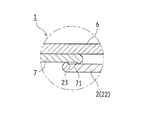
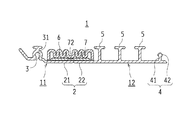
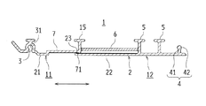
図1は本発明の実施形態1に係るプロファイルを示す断面図である。図2は、図1のプロファイルの延伸時の様子を示す断面図であり、図3は図2のプロファイルの部分拡大図である。
(Embodiment 1)
FIG. 1 is a cross-sectional view showing a profile according to
図1に示すように、プロファイル1は、基板部2の長手方向に沿って複数条のリブ5が立設され、基板部2の両側縁部に接合部(第1接合部及び第2接合部)が備えられて、長尺帯状に形成されている。リブ5は、基板部2の一方の面に立設されている。
As shown in FIG. 1, the
両側縁部の接合部は、相互に嵌め合わせが可能に形成されている。例示の形態では、一方の接合部として接合凹部3が形成され、他方の接合部として前記接合凹部3に嵌合する接合凸部4が形成されている。
The joint portions at both side edges are formed so as to be fitted to each other. In the illustrated embodiment, the
接合凸部4は、支柱部41と断面略三角形状の嵌入部42とを備えている。また、接合凹部3は、接合凸部4の断面形状に対応する凹状の被嵌入部31を備えて形成されている。接合凹部3の側縁部は、斜め外方に延設されている。
The joint
プロファイル1の接合凹部3と接合凸部4との間には、複数条のリブ5が長手方向に沿って立設されている。これらのリブ5の先端部は、断面略T字状に形成されている。リブ5は、プロファイル1が巻回された状態での基板部2の外径側となる面に突設されている。
Between the joint
これにより、プロファイル1の接合凹部3と接合凸部4とは、螺旋状に巻回された際に隣接したプロファイル1の接合凸部4又は接合凹部3に接合される。また、接合凹部3の側縁部は、隣接したプロファイル1の略T字状のリブ5に傾斜状態で係止し、一体状に接合される。
Thereby, the joint
プロファイル1の基板部2は、幅方向の一方側を構成する第1基板部21と、幅方向の他方側を構成する第2基板部22とに分割して形成され、分割されたこれら二部材が幅方向に連続することにより帯板状をなすように構成されている。
The
第1基板部21は、一側縁に、第1接合部としての接合凹部3を備えている。また、第2基板部22は、他側縁に、第2接合部としての接合凸部4を備え、第1基板部21の他側縁側に、第1基板部21と接離自在に並設されている。
The
プロファイル1において、これらの第1基板部21及び第2基板部22は、複数条のリブ5とともに、それぞれ一体成形して形成されている。
In the
図1に示すように、プロファイル1は、第1部材11と第2部材12とを備えている。第1部材11は、接合凹部3と、この接合凹部3につながる第1基板部21とを一体状に成形して形成されている。第2部材12は、接合凸部4と、この接合凸部4につながる第2基板部22と、第2基板部22に立設した複数条のリブ5とを一体状に成形して形成されている。第1部材11と第2部材12とは、第1基板部21と第2基板部22との双方の辺縁部を突き合わせるようにして配置されている。
As shown in FIG. 1, the
第1部材11と第2部材12とは、弾性変形材からなる伸縮部材6により結合されている。伸縮部材6は、第1基板部21及び第2基板部22のリブ立設面に沿って収縮状態で配置されている。
The
例示の形態では、伸縮部材6は、第1基板部21と第2基板部22とにまたがるように、配設されている。伸縮部材6は、その幅方向の両端部にて、第1部材11の接合凹部3の側部と、第2部材12のリブ5とに結合されている。伸縮部材6は、ベローズ形状に形成された弾性変形材からなり、引張力が作用することにより幅方向に伸長可能とされている。
In the illustrated form, the
プロファイル1において、第1部材11及び第2部材12は、合成樹脂系材料を用いて押出成形などによってそれぞれ一体成形されている。合成樹脂系材料には、例えば、ポリエチレン、ポリプロピレンなどを主材料とする可撓性を有する硬質プラスチックが好ましく、ポリ塩化ビニル、ポリエステル、ポリカーボネート、またはこれらの樹脂材をガラス繊維で補強した樹脂材なども好適に用いることができる。
In the
これに対し、伸縮部材6は、ゴム又は熱可塑性エラストマーなどの弾性変形材からなる。
On the other hand, the
例えば、前記ゴムとしては、ブチルゴム、ウレタンゴム、アクリルゴム、シリコーンゴム、エチレン−プロピレン共重合ゴム、エチレン−プロピレン−ジエン三元共重合ゴム等が挙げられる。これらのゴムは、単独で用いられてもよいし、2種類以上が併用されてもよい。 Examples of the rubber include butyl rubber, urethane rubber, acrylic rubber, silicone rubber, ethylene-propylene copolymer rubber, and ethylene-propylene-diene terpolymer rubber. These rubbers may be used alone or in combination of two or more.
前記熱可塑性エラストマーとしては、例えば、イソプレン系エラストマー、オレフィン系エラストマー、エステル系エラストマー、塩化ビニル系エラストマー等が挙げられるが、主材料がポリ塩化ビニルの場合は、塩化ビニル系エラストマーが好ましく、主原料がオレフィン系材料の場合は、オレフィン系エラストマーであることが好ましい。これらの熱可塑性エラストマーは、単独で用いられてもよいし、2種類以上が併用されてもよい。 Examples of the thermoplastic elastomer include isoprene-based elastomers, olefin-based elastomers, ester-based elastomers, and vinyl chloride-based elastomers. When the main material is polyvinyl chloride, a vinyl chloride-based elastomer is preferable and the main raw material is used. When is an olefin material, it is preferably an olefin elastomer. These thermoplastic elastomers may be used alone or in combination of two or more.
伸縮部材6は、例えば、第1部材11と伸縮部材6と第2部材12とを同時に押出成形して、それぞれを押出金型内で一体化させるか、または相互に接着剤等を用いて接着することにより、第1部材11及び第2部材12と一体に形成することができる。
The
このようなゴム又は熱可塑性エラストマーとしては、特に限定されないが、主材料がポリ塩化ビニルの場合は、塩化ビニル系エラストマーが好ましく、主原料がオレフィン系材料の場合は、オレフィン系エラストマーであることが好ましい。 Such a rubber or thermoplastic elastomer is not particularly limited, but is preferably a vinyl chloride elastomer when the main material is polyvinyl chloride, and an olefin elastomer when the main material is an olefin material. preferable.
このような構成により、第1部材11と第2部材12とは、プロファイル1に作用する引張力によって相互に離間することが可能である。また、第1部材11と第2部材12とが離間するのに伴って、両者間に備えられた伸縮部材6が幅方向に伸長してプロファイル1の一体性を保持しつつ、第1部材11と第2部材12とが離間するのを許容する。このため、プロファイル1は幅方向に自在に延伸することが可能であり、その変形によって外力の影響を緩和するとともに局所的に大きな破損を生じるのを回避するものとなる。
With such a configuration, the
例示の形態に係るプロファイル1は、さらに、第1部材11及び第2部材12双方の基板部2(第1基板部21及び第2基板部22)にまたがって、帯板状の閉塞部材7を備えている。閉塞部材7は、基板部2と伸縮部材6との間に納められている。また、閉塞部材7は、第1部材11及び第2部材12と同様の合成樹脂系材料により可撓性を有するように形成されている。
In the
より具体的には、閉塞部材7は、第1基板部21と、第2部材12の辺縁部に延びる第2基板部22との双方に重ねて配設されている。また、閉塞部材7は、第1部材11の接合凹部3から第2部材12の端部寄りのリブ5までの幅間隔に対応する幅寸法を有して形成されている。
More specifically, the closing
閉塞部材7は、図2に示すように、第1部材11と第2部材12とが離間した際には、第1基板部21と第2基板部22との間隙を閉塞する作用をなす。第1部材11と第2部材12とは、閉塞部材7の幅寸法の範囲内において、相互に離間することができるように構成されている。
As shown in FIG. 2, the closing
具体的に、第1基板部21及び第2基板部22には、リブ立設面側の辺縁部に、それぞれ突条部23がそれぞれ設けられている。図3に拡大して示すように、第2基板部22の突条部23に対し、閉塞部材7の辺縁部には係止凸部71が設けられている。これにより、第1基板部21及び第2基板部22の各突条部23と、閉塞部材7の係止凸部71とが相互に係止しうるように形成されている。突条部23と係止凸部71とが係止することによって、第1部材11と第2部材12とは、一定幅以上には離間しないように形成されている。
Specifically, the
また、閉塞部材7の幅寸法、すなわち、閉塞部材7と、第1基板部21及び第2基板部22の双方との重なり代は、伸縮部材6の伸び代よりも大きく確保されている。このため、図2に示すように、伸縮部材6のベローズ形状が引張力により展開され、伸縮部材6が伸長した状態にあっても、第1部材11と第2部材12との間を閉塞部材7が完全に封止しており、両者間に隙間を生じない。また、第1部材11及び第2部材12の突条部23と、閉塞部材7の係止凸部71とが係止するところまで第1部材11及び第2部材12が離間するとき、伸縮部材6は、前記展開された状態からさらに引き伸ばされて弾性的に伸長する。伸縮部材6は、このように伸長しても、両側縁部が第1部材11及び第2部材12に一体状とされているので、延伸したプロファイル1の一体性及び水密性を保持することができる。
Further, the width dimension of the closing
閉塞部材7は、第1部材11及び第2部材12に対し、互いに摺動自在に設けられている。これに対し、閉塞部材7は伸縮部材6に対しては部分的に固着されて、相互に位置ずれが生じないように構成されている。例示の形態では、図1及び図2に示されるように、伸縮部材6のベローズ部の略中央部分と、当該部分に接する閉塞部材7の表面部とが固着されて結合部72が形成されている。
The closing
このような構成に係るプロファイル1は、既設管の直線状の管路だけでなく曲がり部においても良好に管状体を形成し、管壁をライニングするものとなる。図4は、既設管のライニング方法を模式的に示す説明図である。
The
既設管のライニング方法について簡単に説明すると、図4に示すように、既設管10にはマンホール101、102が設けられており、更生対象領域のマンホール101、102を利用して既設管10内にプロファイル1が導入される。
The existing pipe lining method will be briefly described. As shown in FIG. 4,
一方のマンホール101の近傍には、プロファイル1を巻き付けたドラム103を配置し、他方のマンホール102の近傍に電源(発電機)104を配置している。また、製管機105と、油圧ユニット106を載置した台車107とを、マンホール101から既設管10内に搬入する。そして、ドラム103からプロファイル1を引き出してマンホール101内へ供給し、製管機105を用いてプロファイル1を螺旋状に巻回する。このとき、プロファイル1の隣接した接合凹部3と接合凸部4とを接合して、管状に製管する。
A
プロファイル1は、既設管10内で螺旋状に巻回される際に、管路に曲がり部があっても幅方向に柔軟に延伸するので、作業の中断を招くことがなく、スムーズに製管を進めることを可能にする。また、プロファイル1はリブ立設面の反対面が平滑に形成されており、大きな凹凸がないので、形成された更生管の内周面が平滑となり、円滑な水流を確保することができる。
When the
また、かかる構成のプロファイル1とすることにより、更生管としての供用後、地盤沈下や地震等により大きな外力が作用しても、図2に示したように、第1部材11と第2部材12とが相互に離間するとともに、伸縮部材6が幅方向に伸長して変形することにより、局部的な破損が生じるのを回避することができる。よって、既設管10に損傷を生じたとしても、既設管10内の更生管に対する損傷は最小限にとどめることができ、プロファイル1が延伸して管状を保持するので、流路を確保することが可能となる。
Moreover, by setting it as the
なお、プロファイル1には、隣り合うリブ5間に図示しない金属製補強材が備えられてもよい。例えば、第2部材12に2つ以上のリブが形成されている場合には、隣り合うリブ5管に金属板からなる補強材を設けることができる。補強材は多様な形態で形成することができ、鋼板、ステンレス板等からなる金属板を例えば断面略W字状や略U字状に成形したものを用いる。
The
(実施形態2)
次に、本発明に係るプロファイルの実施形態2について説明する。図5(a)は本発明の実施形態2に係るプロファイル1の断面図であり、図5(b)は図5(a)のプロファイル1の接合部を接合する様子を示す部分拡大斜視図である。
(Embodiment 2)
Next, a second embodiment of the profile according to the present invention will be described. FIG. 5A is a cross-sectional view of the
実施形態2に係るプロファイル1は、第1基板部21、第2基板部22、リブ5、伸縮部材6、及び閉塞部材7の構成が前記実施形態1のものと同様であるので、図5(a)及び図5(b)にあっては共通の構成に前記実施形態1と共通の符号を用いて示し、それらの詳細な説明を省略する。
The
前記実施形態1では、プロファイル1の側縁部に形成された接合凹部3と接合凸部4とが相互に嵌め合わされて接合される構成であった。本実施形態では、それに代えてプロファイル1の接合部として、幅方向の両側縁部に、接合凹部33、34が形成され、コネクタ8を用いてこれらの接合凹部33、34を接合する構成とされている。
In the first embodiment, the joint
具体的に、このプロファイル1は、一側縁部に接合凹部33(第1接合部)が設けられ、他側縁部に、前記接合凹部33と対称形状をなす接合凹部34(第2接合部)が設けられている。接合凹部33,34は、ともに被嵌入部を備えている。
Specifically, this
コネクタ8は、長尺状に形成され、巻回によって隣り合うプロファイル1にまたがって配設される。図示するように、コネクタ8には、隣接した2つの接合凹部33、33を合わせた凹部形状に対応する2つの凸部81、81が形成されている。
The
プロファイル1は、例えば、両側縁部の接合凹部33、34の一方の接合凹部33に、コネクタ8の凸部81の一方が嵌め込まれた状態で、製管機105に供給されて螺旋状に巻回される。そして、巻回過程において、互いに隣接したプロファイル1の他方の接合凹部34に、コネクタ8の他方の凸部81が嵌め合わされて、プロファイル1が接合される。
For example, the
このようなプロファイル1も前記実施形態1と同様に、引張力に対して幅方向に延伸可能とされている。プロファイル1は、一方の接合凹部33と、この接合凹部33につながる第1基板部21を備えて形成された第1部材11と、他方の接合凹部34と、複数条のリブ5と、これらにつながる第2基板部22を備えて形成された第2部材12とが、伸縮部材6により結合されて一体状とされている。
Similarly to the first embodiment, such a
伸縮部材6は、第1部材11側の接合凹部33と、この接合凹部33に隣り合う第2部材12側のリブ5との間に設けられている。伸縮部材6と、第1基板部21及び第2基板部22との間には、両基板部21、22の境界部にまたがるように、閉塞部材7が重ねて備えられている。
The
本実施形態に係るプロファイル1の場合も、プロファイル1が幅方向への引張力を受けたとき、第1部材11と第2部材12とが離間するとともに、伸縮部材6が伸長する。また、プロファイル1における第1部材11と第2部材12との間隙は、閉塞部材7により封止される。よって、プロファイル1が幅方向に延伸して外力を吸収し、更生管の内周面の平滑性を保持しつつ、局部的な損傷が生じるのを回避することができる。したがって、既設管に損傷が生じたとしても、更生管の内部(プロファイル1の内面側)では流路を確保することが可能となる。
Also in the case of the
(実施形態3)
次に、本発明に係るプロファイルの実施形態3について説明する。図6は本発明の実施形態3に係るプロファイル1の断面図である。
(Embodiment 3)
Next, a third embodiment of the profile according to the present invention will be described. FIG. 6 is a cross-sectional view of the
前記実施形態1では、伸縮部材6がその幅方向の両端部にて、第1部材11の接合凹部3の側部と、第2部材12のリブ5とに結合されていた。本実施形態では、それに代えて伸縮部材6の両端部が、それぞれ第1基板部21と、第2基板部22とに対して結合された構成としている。
In the first embodiment, the expansion /
その他、リブ5、閉塞部材7、接合凹部3及び接合凸部4の構成は、前記実施形態1のものと同様であるため、図6にあっては実施形態1と同じ符号を用いて示し、それらの詳細な説明を省略する。
In addition, since the structure of the
このように伸縮部材6を、第1基板部21と、第2基板部22とに結合して形成した場合も、第1基板部21及び第2基板部22のリブ立設面側に沿って収縮状態で配置されている。
As described above, even when the
伸縮部材6は、引張力が作用した際の第1部材11と第2部材12との離間に追従して伸長し、プロファイル1の一体性を保持する。これにより、プロファイル1は幅方向に延伸することが可能であり、このような変形作用によって外力を柔軟に吸収し局所的な破損を防ぐものとなる。
The
(実施形態4)
次に、本発明に係るプロファイルの実施形態4について説明する。図7は本発明の実施形態4に係るプロファイル1の断面図であり、図8は図7のプロファイル1の延伸時の様子を示す断面図である。
(Embodiment 4)
Next, a fourth embodiment of the profile according to the present invention will be described. FIG. 7 is a cross-sectional view of the
前記実施形態1では、閉塞部材7が第1基板部21と第2基板部22とにまたがって設けられ、これらの両基板部21、22と伸縮部材6との間に納められていた。本実施形態では、それに代えて閉塞部材7が、第1基板部21又は第2基板部22のいずれか一方の基板部に対して一体状に連設された構成としている。
In the first embodiment, the closing
その他、接合凹部3、接合凸部4、リブ5及び伸縮部材6の構成は、前記実施形態1のものと同様であるため、図7、8にあっては実施形態1と同じ符号を用いて示し、それらの詳細な説明を省略する。
In addition, since the structure of the joining recessed
図7に示す形態では、プロファイル1の第2部材12は、接合凸部4、複数条のリブ5、及び接合凸部4につながる第2基板部22を備えて形成されている。これに対し、第1部材11は、接合凹部3と、この接合凹部3につながる第1基板部21を備えて形成されている。さらに、この第1部材11には、第1基板部21に連なって閉塞部材7が一体状に設けられている。
In the form shown in FIG. 7, the
閉塞部材7は、第1基板部21に対し段部24を介して連設されている。第1基板部21及び第2基板部22は、ともに同等の厚みを有して形成されている。段部24は、第2基板部22の厚みに対応させて形成されている。閉塞部材7は、第2基板部22に重なり合って配設され、段部24が第2基板部22の側部に当接している。
The closing
第1部材11に一体状に連設された閉塞部材7は、第2基板部22の側縁部から、第2部材12側のリブ5の側部まで延設されている。また、第2部材12側の辺縁部に延設された第2基板部22は、閉塞部材7とほぼ等しい幅寸法で設けられ、閉塞部材7との重なり幅を確保している。
The closing
この場合にも、伸縮部材6はベローズ形状に形成されて、閉塞部材7に重ねて配設されている。伸縮部材6の両端部は、第1部材11の接合凹部3の側部と、第2部材12のリブ5とに結合されている。
Also in this case, the expansion /
また、前記実施形態1にて図3により示した構成と同様に、閉塞部材7の辺縁部には、係止凸部(71)が設けられている。これに対し、第2基板部22の辺縁部には、リブ立設面に、前記係止凸部に係止する突条部(23)が設けられている。これらの突条部と係止凸部とが係止することにより、第1部材11と第2部材12との一定以上の離間を規制している。
Further, similarly to the configuration shown in FIG. 3 in the first embodiment, a locking projection (71) is provided on the edge of the closing
本実施形態に係るプロファイル1の場合も、幅方向への引張力を受けると、図8に示すように第1部材11と第2部材12とが相互に離間するとともに、伸縮部材6が幅方向に伸長する。また、第1部材11と第2部材12が相互に離間することにより、第2基板部22に沿って閉塞部材7が摺動する。プロファイル1における第1基板部21と第2基板部22との間隙は、この閉塞部材7により封止される。
Also in the case of the
よって、プロファイル1が幅方向に延伸して外力を吸収し、平滑な内面を保持するので、局部的な破断や座屈が生じるのを回避することができ、既設管に損傷が生じたとしても、プロファイル1の内面側では流路を確保することが可能となる。
Therefore, since the
(実施形態5)
次に、本発明に係るプロファイルの実施形態5について説明する。図9は本発明の実施形態5に係るプロファイル1の断面図であり、図10は図9のプロファイル1の延伸時の様子を示す断面図である。
(Embodiment 5)
Next, a fifth embodiment of the profile according to the present invention will be described. FIG. 9 is a cross-sectional view of the
前記実施形態4では、閉塞部材7が第1基板部21に一体状に連設され、第2基板部22に重ねて配設されていた。また、伸縮部材6は、第1部材11の接合凹部3と、第2部材12のリブ5との間に設けられていた。本実施形態では、閉塞部材7が、第1基板部21に対して一体状に連設された点は前記実施形態4と共通であるが、第1部材11側にもリブ15が備えられており、伸縮部材6が第1部材11側のリブ15と、このリブ15に隣り合う第2部材12側のリブ5との間に設けられた点に特徴がある。
In the fourth embodiment, the closing
その他、接合凹部3及び接合凸部4等の基本構成は、前記実施形態4のものと同様であるため、図9、10にあっては実施形態4と同じ符号を用いて示し、それらの詳細な説明を省略する。
In addition, since the basic configuration of the bonding
図9に示すように、第1部材11は、接合凹部3、第1基板部21、及びリブ15を備えて形成されている。第1基板部21には閉塞部材7が延設されている。第1基板部21と閉塞部材7とは、段部24を介して一体状に連設されている。
As shown in FIG. 9, the
第2部材12は、接合凸部4、複数条のリブ5、及び接合凸部4につながる第2基板部22を備えて一体に形成されている。閉塞部材7は、第2基板部22に重なり合うように配設されている。これにより、第1部材11と第2部材12とは、幅方向に互いに離間することが可能とされている。
The
また、プロファイル1は、全体として3つのリブ15、5が立設されている。このうちの1つのリブ15が、前記のとおり第1部材11側に一体に設けられている。このリブ15は、第1部材11に延設された閉塞部材7の辺縁部に立設されている。なお、リブ15は、第2部材12側に立設された他のリブ5と同形状に形成されている。
Further, the
閉塞部材7の辺縁部には、リブ15の反対側に係止凸部71が突設されている。これに対し、第2基板部22の辺縁部には、リブ立設面に、前記係止凸部71に係止する突条部23が設けられている。これらの突条部23と係止凸部71とが係止することにより、第1部材11と第2部材12との一定以上の離間を規制している。
A locking
伸縮部材6は、第1部材11側のリブ15と、このリブ15に隣り合う第2部材12側のリブ65との間に設けられて、これらの第1部材11と第2部材12とを一体状に結合している。また、伸縮部材6は、閉塞部材7に重ねて配設されるのではなく、第2基板部22のリブ立設面に沿って収縮状態で配置されている。伸縮部材6は、第1部材11側のリブ15と第2部材12側のリブ5とに対して、押出金型内で一体化させるか接着剤により接合されている。伸縮部材6は、ゴム又は熱可塑性エラストマーなどの弾性変形材からなり、作用する引張力に応じて自在に伸長する。
The
このようなプロファイル1では、幅方向の引張力を受けたとき、図10に示すように、第1部材11と第2部材12とが相互に離間するとともに、両者間に配設されている伸縮部材6が幅方向に伸長する。また、第1部材11と第2部材12が相互に離間することにより、第1基板部21に延設された閉塞部材7が、第2基板部22に沿って摺動する。第1基板部21と第2基板部22との間隙は、閉塞部材7が配設されることとなり、プロファイル1の一体性を保つとともに、第1部材11と第2部材12との間を封止する。このとき、リブ15の反対側に突出した係止凸部71、第2基板部22の突条部23とが係止すると、第1部材11と第2部材12とのそれ以上の離間が規制される。これにより、プロファイル1は、全体として幅方向に延伸され、このような変形作用によって外力を柔軟に吸収し局所的な破損を防ぐものとなる。
In such a
(実施形態6)
次に、本発明に係るプロファイルの実施形態6について説明する。図11は本発明の実施形態6に係るプロファイル1の断面図である。
(Embodiment 6)
Next, a sixth embodiment of the profile according to the present invention will be described. FIG. 11 is a cross-sectional view of a
前記実施形態4では、閉塞部材7が第1基板部21に一体状に連設され、第2基板部22に重ねられて配設されていた。また、伸縮部材6は、第1部材11の接合凹部3と、第2部材12のリブ5との間に設けられていた。本実施形態では、閉塞部材7が、第2基板部22に対して一体状に連設され、第1基板部21に重なり合うように構成されている。
In the fourth embodiment, the closing
その他、接合凹部3及び接合凸部4等の基本構成は、前記実施形態4のものと同様であるため、図11にあっては実施形態4と同じ符号を用いて示し、それらの詳細な説明を省略する。
In addition, since the basic configuration of the
図11に示すように、第1部材11は、接合凹部3と、この接合凹部3につながる第1基板部21を備えて一体に形成されている。第2部材12は、複数条のリブ5、51、接合凸部4、及び接合凸部4につながる第2基板部22を備えて一体に形成されている。さらに、第2基板部22には、第1部材11との間を塞ぐ閉塞部材7が一体状に設けられている。
As shown in FIG. 11, the
閉塞部材7は、第2基板部22に対し段部24を介して連設されている。第1部材11側及び第2基板部22はともに同等の厚みを有して形成されている。段部24は、第1基板部21の厚みに対応させて形成されており、閉塞部材7が重ねられた第1基板部21の側縁部に当接している。
The closing
また、第1基板部21の辺縁部には突条部23が設けられている。また、閉塞部材7の辺縁部には、第1部材11寄りのリブ51の反対側に、係止凸部71が突設されている。これらの突条部23と係止凸部71とが係止することにより、第1部材11と第2部材12との一定以上の離間を規制している。
Further, a
伸縮部材6は、第1部材11の接合凹部3と、第2部材12の端部のリブ51との間に設けられている。この場合、伸縮部材6は、閉塞部材7に重ねて配設されるのではなく、第1基板部21のリブ立設面側に沿って収縮状態で配置されている。伸縮部材6の両端部は、押出金型内で一体化させるか接着することにより固着されている。
The
本実施形態に係るプロファイル1においても、幅方向への引張力を受けたとき、第1部材11と第2部材12とが相互に離間するとともに、両者間に配設されている伸縮部材6が幅方向に伸長する。また、第1部材11と第2部材12が相互に離間することにより、第2基板部22に延設された閉塞部材7が、第1基板部21に沿って摺動する。第1基板部21と第2基板部22との間隙は、閉塞部材7により閉塞されて封止される。これにより、プロファイル1は、全体として幅方向に延伸され、このような変形作用によって外力を柔軟に吸収し局所的な破損を防ぐものとなる。
Also in the
(他の実施形態)
本発明に係るプロファイル1は、前記の実施形態以外にも他の様々な形で実施することができる。例えば、プロファイル1の第1接合部及び第2接合部の形態、及びリブ5の形状及び数等は、どのような構成であってもよい。また、伸縮部材6も前記実施形態の形状及び配置例に限られるものではなく、第1部材11と第2部材12とを結合し、伸縮自在な構成であれば、どのような構成であってもよい。そのため、前記の実施形態はあくまでも例示であり、限定的なものではない。
(Other embodiments)
The
以上説明したように、本発明に係るプロファイル1により更生管を形成する際、既設管の管路の曲がり部への追従性を発揮して、円滑にライニング作業を進めることが可能となる。また、形成された更生管は、第1基板部21及び第2基板部22からなる内周面が平滑に形成されるので、円滑な水流を確保することが可能となる。さらに、地盤沈下等の発生時や地震等の災害時には、第1部材11と第2部材12とが離間するとともに伸縮部材6が伸長することにより幅方向に延伸して変形を許容し、更生管の内周面の平滑性を維持したまま管路としての機能を維持することが期待できる。
As described above, when the rehabilitation pipe is formed by the
本発明は、既設管を更生するライニング材として好適に利用可能である。 The present invention can be suitably used as a lining material for rehabilitating existing pipes.
1 プロファイル
11 第1部材
12 第2部材
15 リブ
2 基板部
21 第1基板部
22 第2基板部
23 突条部
24 段部
3 接合凹部
31 被嵌入部
33 接合凹部
34 接合凹部
4 接合凸部
41 支柱部
42 嵌入部
5 リブ
6 伸縮部材
7 閉塞部材
71 係止凸部
72 結合部
8 コネクタ
81 凸部
10 既設管
101、102 マンホール
103 ドラム
104 発電機
105 製管機
106 油圧ユニット
107 台車
DESCRIPTION OF
Claims (11)
他側縁に第2接合部を備え前記第1基板部の他側縁側に該第1基板部と接離自在に並設された長尺帯状の第2基板部と、
前記第1基板部と第2基板部とを結合する伸縮部材と、
前記第1基板部と第2基板部とが離間状態にあるときこれら第1基板部と第2基板部との間隙を閉塞する閉塞部材と、
を備えたことを特徴とするプロファイル。 A long strip-shaped first substrate portion provided with a first joining portion on one side edge;
A second band-shaped second substrate portion provided with a second bonding portion on the other side edge and arranged in parallel with the first substrate portion on the other side edge side of the first substrate portion;
A stretchable member for joining the first substrate portion and the second substrate portion;
A closing member that closes a gap between the first substrate portion and the second substrate portion when the first substrate portion and the second substrate portion are in a separated state;
A profile characterized by comprising.
前記第2基板部には複数条のリブが立設され、
前記伸縮部材は、前記第1接合部と、該第1接合部に隣り合う第2基板部側のリブとの間に設けられていることを特徴とするプロファイル。 The profile of claim 1,
A plurality of ribs are erected on the second substrate portion,
The profile characterized in that the elastic member is provided between the first joint part and a rib on the second substrate part side adjacent to the first joint part.
前記第1基板部及び第2基板部には複数条のリブが立設され、
前記伸縮部材は、前記第1基板部側のリブと、このリブに隣り合う第2基板部側のリブとの間に設けられていることを特徴とするプロファイル。 The profile of claim 1,
A plurality of ribs are erected on the first substrate portion and the second substrate portion,
The profile, wherein the elastic member is provided between a rib on the first substrate portion side and a rib on the second substrate portion side adjacent to the rib.
前記伸縮部材は、前記第1基板部と第2基板部とにまたがって設けられていることを特徴とするプロファイル。 The profile of claim 1,
The profile characterized in that the elastic member is provided across the first substrate portion and the second substrate portion.
前記伸縮部材は弾性変形材からなり、収縮状態で配置されていることを特徴とするプロファイル。 In the profile according to any one of claims 1 to 4,
The profile characterized in that the elastic member is made of an elastically deformable material and is arranged in a contracted state.
前記伸縮部材は、ゴム又は熱可塑性エラストマーからなることを特徴とするプロファイル。 The profile according to claim 5,
2. The profile according to claim 1, wherein the elastic member is made of rubber or a thermoplastic elastomer.
前記伸縮部材は、両側縁部が第1基板部側と第2基板部側とに対して押出金型内で一体化させることにより接合されていることを特徴とするプロファイル。 In the profile according to any one of claims 1 to 6,
The profile characterized by the said elastic member being joined by integrating both side edge parts with respect to the 1st board | substrate part side and the 2nd board | substrate part side within an extrusion die.
前記第1基板部と前記第2基板部とは、双方の辺縁部を突き合わせて配置され、突き合わせられた前記第1基板部と前記第2基板部との境界部にまたがって前記閉塞部材が付設されていることを特徴とするプロファイル。 In the profile according to any one of claims 1 to 7,
The first substrate portion and the second substrate portion are disposed so that the edge portions of the first substrate portion and the second substrate portion are abutted against each other, and the blocking member extends across a boundary portion between the abutted first substrate portion and the second substrate portion. A profile characterized by being attached.
前記閉塞部材は、前記第1基板部と前記第2基板部とのいずれか一方の基板部に一体状に連設され、他方の基板部に重ねて配設されていることを特徴とするプロファイル。 In the profile according to any one of claims 1 to 7,
The profile is characterized in that the closing member is integrally connected to one of the first substrate portion and the second substrate portion, and is disposed so as to overlap the other substrate portion. .
前記閉塞部材の幅方向の両側部には係止凸部が設けられ、第1基板部の辺縁部及び第2基板部の辺縁部には前記係止凸部に係止する突条部が設けられたことを特徴とするプロファイル。 In the profile according to any one of claims 1 to 9,
Locking protrusions are provided on both side portions of the closing member in the width direction, and protrusions that lock the locking protrusions on the edge of the first substrate portion and the edge of the second substrate portion. A profile characterized in that is provided.
前記閉塞部材は、幅寸法が前記伸縮部材の伸び代よりも大きく形成されていることを特徴とするプロファイル。 In the profile according to any one of claims 1 to 10,
The profile characterized in that the closing member is formed so that a width dimension is larger than an extension allowance of the elastic member.
Priority Applications (1)
| Application Number | Priority Date | Filing Date | Title |
|---|---|---|---|
| JP2011075697A JP5703093B2 (en) | 2011-03-30 | 2011-03-30 | Profile |
Applications Claiming Priority (1)
| Application Number | Priority Date | Filing Date | Title |
|---|---|---|---|
| JP2011075697A JP5703093B2 (en) | 2011-03-30 | 2011-03-30 | Profile |
Publications (2)
| Publication Number | Publication Date |
|---|---|
| JP2012206471A true JP2012206471A (en) | 2012-10-25 |
| JP5703093B2 JP5703093B2 (en) | 2015-04-15 |
Family
ID=47186651
Family Applications (1)
| Application Number | Title | Priority Date | Filing Date |
|---|---|---|---|
| JP2011075697A Expired - Fee Related JP5703093B2 (en) | 2011-03-30 | 2011-03-30 | Profile |
Country Status (1)
| Country | Link |
|---|---|
| JP (1) | JP5703093B2 (en) |
Cited By (3)
| Publication number | Priority date | Publication date | Assignee | Title |
|---|---|---|---|---|
| JP2018202857A (en) * | 2017-06-01 | 2018-12-27 | 栄光テクノ株式会社 | Connecting member of lining pipe for sewer |
| JP2021142694A (en) * | 2020-03-11 | 2021-09-24 | 積水化学工業株式会社 | Belt-like member for helical pipe and helical pipe |
| JP2022039711A (en) * | 2020-08-28 | 2022-03-10 | 積水化学工業株式会社 | Belt-like member for helical pipe |
Citations (9)
| Publication number | Priority date | Publication date | Assignee | Title |
|---|---|---|---|---|
| JP2000254970A (en) * | 1998-08-10 | 2000-09-19 | Sekisui Chem Co Ltd | Rehabilitation method of existing pipe having straight pipe section and curved section and connecting member of band |
| JP2000272006A (en) * | 1999-03-25 | 2000-10-03 | Sekisui Chem Co Ltd | Spiral tube forming method and existing pipe rehabilitation method |
| JP2002144426A (en) * | 2000-11-16 | 2002-05-21 | Sekisui Chem Co Ltd | Inner lining member for pipe sewer and method of manufacturing the same |
| JP2004130538A (en) * | 2002-10-08 | 2004-04-30 | Osaka Bosui Constr Co Ltd | Pipe inner lining method |
| JP2004251340A (en) * | 2003-02-19 | 2004-09-09 | Kubota Corp | Joiner |
| JP2006256212A (en) * | 2005-03-18 | 2006-09-28 | Kubota Construction Co Ltd | Lining method |
| JP2008105267A (en) * | 2006-10-25 | 2008-05-08 | Sekisui Chem Co Ltd | Rehabilitation of existing pipes |
| JP2008307784A (en) * | 2007-06-14 | 2008-12-25 | Sekisui Chem Co Ltd | Existing pipe lining strip and lining method |
| JP2011052706A (en) * | 2009-08-31 | 2011-03-17 | Kubota-Ci Co | Strip for forming helical tube |
-
2011
- 2011-03-30 JP JP2011075697A patent/JP5703093B2/en not_active Expired - Fee Related
Patent Citations (9)
| Publication number | Priority date | Publication date | Assignee | Title |
|---|---|---|---|---|
| JP2000254970A (en) * | 1998-08-10 | 2000-09-19 | Sekisui Chem Co Ltd | Rehabilitation method of existing pipe having straight pipe section and curved section and connecting member of band |
| JP2000272006A (en) * | 1999-03-25 | 2000-10-03 | Sekisui Chem Co Ltd | Spiral tube forming method and existing pipe rehabilitation method |
| JP2002144426A (en) * | 2000-11-16 | 2002-05-21 | Sekisui Chem Co Ltd | Inner lining member for pipe sewer and method of manufacturing the same |
| JP2004130538A (en) * | 2002-10-08 | 2004-04-30 | Osaka Bosui Constr Co Ltd | Pipe inner lining method |
| JP2004251340A (en) * | 2003-02-19 | 2004-09-09 | Kubota Corp | Joiner |
| JP2006256212A (en) * | 2005-03-18 | 2006-09-28 | Kubota Construction Co Ltd | Lining method |
| JP2008105267A (en) * | 2006-10-25 | 2008-05-08 | Sekisui Chem Co Ltd | Rehabilitation of existing pipes |
| JP2008307784A (en) * | 2007-06-14 | 2008-12-25 | Sekisui Chem Co Ltd | Existing pipe lining strip and lining method |
| JP2011052706A (en) * | 2009-08-31 | 2011-03-17 | Kubota-Ci Co | Strip for forming helical tube |
Cited By (5)
| Publication number | Priority date | Publication date | Assignee | Title |
|---|---|---|---|---|
| JP2018202857A (en) * | 2017-06-01 | 2018-12-27 | 栄光テクノ株式会社 | Connecting member of lining pipe for sewer |
| JP2021142694A (en) * | 2020-03-11 | 2021-09-24 | 積水化学工業株式会社 | Belt-like member for helical pipe and helical pipe |
| JP7412232B2 (en) | 2020-03-11 | 2024-01-12 | 積水化学工業株式会社 | Strip member for spiral tube and spiral tube |
| JP2022039711A (en) * | 2020-08-28 | 2022-03-10 | 積水化学工業株式会社 | Belt-like member for helical pipe |
| JP7492409B2 (en) | 2020-08-28 | 2024-05-29 | 積水化学工業株式会社 | Belt-shaped member for helical pipe |
Also Published As
| Publication number | Publication date |
|---|---|
| JP5703093B2 (en) | 2015-04-15 |
Similar Documents
| Publication | Publication Date | Title |
|---|---|---|
| JP5965754B2 (en) | Pipe rehabilitation method using a strip for spiral wound tube formation and spiral wound tube | |
| JP6559920B1 (en) | Pipeline rehabilitation method and rehabilitation pipe | |
| JP7534750B2 (en) | Pipe rehabilitation materials | |
| JP6755784B2 (en) | Rehabilitation pipeline structure and strip-shaped member for lining | |
| JP5703093B2 (en) | Profile | |
| JPH06143420A (en) | Beltlike body for lining of existing pipe | |
| JP6518354B2 (en) | Connecting member for lining pipe | |
| JP3779037B2 (en) | Strip for existing pipe lining | |
| KR100426405B1 (en) | Drainage channel pipe connection device, especially facilitating use in curved part according to structure of construction spot | |
| JP7412232B2 (en) | Strip member for spiral tube and spiral tube | |
| JP6557529B2 (en) | Seismic structure at the connection between manhole side wall and pipe | |
| JP6267585B2 (en) | Pipe making components | |
| KR200379070Y1 (en) | Water leakage prevention member | |
| JP7462226B2 (en) | Pipe rehabilitation materials | |
| JP2015227054A (en) | Joining structure of belt-like member of regeneration pipe | |
| JP5502433B2 (en) | Joining member for water stop of concrete waterway material and method for joining concrete waterway material | |
| JP4937028B2 (en) | Pipe rehabilitation member | |
| JP7290252B2 (en) | Pipe rehabilitation member | |
| JP7767106B2 (en) | Inner surface member connecting material, pipeline lining structure equipped with same, and pipeline lining method | |
| JP2005083426A (en) | Corrugated tube connection structure | |
| JP5491105B2 (en) | Strip, joining structure of strip and joiner, and spiral tube using the same | |
| JP5442493B2 (en) | Device for reinforcing annular body in water stop device | |
| JP5727863B2 (en) | Water stop member for manhole repair and manhole repair method | |
| KR101030797B1 (en) | Packing stopper | |
| JP2000008504A (en) | Waterproofing method for concrete joints and watertight joints |
Legal Events
| Date | Code | Title | Description |
|---|---|---|---|
| A621 | Written request for application examination |
Free format text: JAPANESE INTERMEDIATE CODE: A621 Effective date: 20131118 |
|
| A977 | Report on retrieval |
Free format text: JAPANESE INTERMEDIATE CODE: A971007 Effective date: 20141006 |
|
| A131 | Notification of reasons for refusal |
Free format text: JAPANESE INTERMEDIATE CODE: A131 Effective date: 20141104 |
|
| A521 | Written amendment |
Free format text: JAPANESE INTERMEDIATE CODE: A523 Effective date: 20141219 |
|
| TRDD | Decision of grant or rejection written | ||
| A01 | Written decision to grant a patent or to grant a registration (utility model) |
Free format text: JAPANESE INTERMEDIATE CODE: A01 Effective date: 20150203 |
|
| A61 | First payment of annual fees (during grant procedure) |
Free format text: JAPANESE INTERMEDIATE CODE: A61 Effective date: 20150223 |
|
| LAPS | Cancellation because of no payment of annual fees |