JP2012207392A - Vehicle door opening/closing controller - Google Patents

Vehicle door opening/closing controller Download PDF

Info

Publication number
JP2012207392A
JP2012207392A JP2011072059A JP2011072059A JP2012207392A JP 2012207392 A JP2012207392 A JP 2012207392A JP 2011072059 A JP2011072059 A JP 2011072059A JP 2011072059 A JP2011072059 A JP 2011072059A JP 2012207392 A JP2012207392 A JP 2012207392A
Authority
JP
Japan
Prior art keywords
rear gate
switch
motor
vehicle door
drive circuit
Prior art date
Legal status (The legal status is an assumption and is not a legal conclusion. Google has not performed a legal analysis and makes no representation as to the accuracy of the status listed.)
Withdrawn
Application number
JP2011072059A
Other languages
Japanese (ja)
Inventor
Shinichi Sato
真一 佐藤
Hitoshi Kazeki
仁志 風木
Current Assignee (The listed assignees may be inaccurate. Google has not performed a legal analysis and makes no representation or warranty as to the accuracy of the list.)
Astemo Ltd
Original Assignee
Keihin Corp
Priority date (The priority date is an assumption and is not a legal conclusion. Google has not performed a legal analysis and makes no representation as to the accuracy of the date listed.)
Filing date
Publication date
Application filed by Keihin Corp filed Critical Keihin Corp
Priority to JP2011072059A priority Critical patent/JP2012207392A/en
Publication of JP2012207392A publication Critical patent/JP2012207392A/en
Withdrawn legal-status Critical Current

Links

Images

Landscapes

  • Lock And Its Accessories (AREA)

Abstract

【課題】車両扉のラッチ解除に使用されるモータに対する常時給電状態を回避することの可能な車両扉開閉制御装置を提供する。
【解決手段】車両扉のラッチ解除に使用されるモータを駆動する駆動回路と、一定条件下で前記車両扉の開放操作が為された場合に前記モータの回転によってラッチ解除されるよう前記駆動回路を制御する制御部とを備える車両扉開閉制御装置であって、前記モータに接続された外部接続端子と前記駆動回路との間の電流経路に電流遮断スイッチが介挿されている。
【選択図】図3
A vehicle door opening / closing control device capable of avoiding a constant power supply state with respect to a motor used for releasing the latch of the vehicle door is provided.
A drive circuit for driving a motor used for unlatching of a vehicle door, and the drive circuit for releasing the latch by rotation of the motor when the opening operation of the vehicle door is performed under a certain condition. A vehicle door opening / closing control device including a control unit that controls a motor, wherein a current cut-off switch is interposed in a current path between an external connection terminal connected to the motor and the drive circuit.
[Selection] Figure 3

Description

本発明は、車両扉開閉制御装置に関する。  The present invention relates to a vehicle door opening / closing control device.

近年では、車両を利用するユーザの利便性向上を図るために、一定条件下でユーザによるスイッチ操作或いはリモコン操作が為された場合に、スライドドアやリアゲート(バックドア或いはテールゲートと同義)等の車両扉を自動的に開閉する車両扉自動開閉システム(所謂、パワースライドドアシステムやパワーリアゲートシステム等)を搭載した車両が普及している(下記特許文献1参照)。  In recent years, in order to improve the convenience of users using vehicles, when a switch operation or remote control operation is performed by a user under certain conditions, a slide door, a rear gate (synonymous with a back door or a tail gate), etc. Vehicles equipped with a vehicle door automatic opening / closing system that automatically opens and closes a vehicle door (so-called power slide door system, power rear gate system, etc.) are widely used (see Patent Document 1 below).

一般的に、この車両扉自動開閉システムは、車両扉のラッチ状態をハーフラッチ状態(半ドア状態)からフルラッチ状態(全閉状態)に自動的に切替えるクロージャーユニットを備えている(下記特許文献2参照)。クロージャーユニットは、制御ユニットから供給される駆動電流によって回転するクロージャーモータを備えており、このクロージャーモータの正転動作時に車両扉のラッチが解除される(フルラッチ状態からハーフラッチ状態となる)。  Generally, this vehicle door automatic opening / closing system includes a closure unit that automatically switches the latch state of the vehicle door from a half latch state (half door state) to a full latch state (fully closed state) (Patent Document 2 below). reference). The closure unit includes a closure motor that is rotated by a drive current supplied from the control unit, and the latch of the vehicle door is released during normal rotation of the closure motor (from a full latch state to a half latch state).

特開2010−159605号公報JP 2010-159605 A 特開2006−9485号公報JP 2006-9485 A

従来では、制御ユニットの内部故障によって、クロージャーモータに対して常時給電状態になると、クロージャーモータの制御が不能となり、車両扉のラッチが解除され、ドアロックが解除状態またはラッチが解除されドアが開放状態となる可能性がある。  Conventionally, if the closure motor is constantly powered due to an internal failure of the control unit, the closure motor cannot be controlled, the vehicle door latch is released, the door lock is released, or the latch is released and the door is opened. There is a possibility of a state.

本発明は、上述した事情に鑑みてなされたものであり、車両扉のラッチ解除に使用されるモータに対する常時給電状態を回避することの可能な車両扉開閉制御装置を提供することを目的とする。    The present invention has been made in view of the above-described circumstances, and an object of the present invention is to provide a vehicle door opening / closing control device capable of avoiding a constant power supply state with respect to a motor used for unlocking a vehicle door. .

上記目的を達成するために、本発明では、車両扉開閉制御装置に係る第1の解決手段として、車両扉のラッチ解除に使用されるモータを駆動する駆動回路と、一定条件下で前記車両扉の開放操作が為された場合に前記モータの回転によってラッチ解除されるよう前記駆動回路を制御する制御部とを備える車両扉開閉制御装置であって、前記モータに接続された外部接続端子と前記駆動回路との間の電流経路に電流遮断スイッチが介挿されていることを特徴とする。  In order to achieve the above object, according to the present invention, as a first solution means for a vehicle door opening / closing control device, a drive circuit for driving a motor used for unlatching a vehicle door, and the vehicle door under certain conditions And a controller for controlling the drive circuit so that the latch is released by the rotation of the motor when the opening operation is performed, and an external connection terminal connected to the motor and the control circuit A current cut-off switch is inserted in a current path between the drive circuit and the drive circuit.

また、本発明では、車両扉開閉制御装置に係る第2の解決手段として、上記第1の解決手段において、前記制御部とは別に設けられ、前記電流遮断スイッチを、前記一定条件下で車両扉の開放操作が為された場合にオフからオンに制御する制御論理回路を備えることを特徴とする。  According to the present invention, as a second solving means related to the vehicle door opening / closing control device, in the first solving means, the current cut-off switch is provided separately from the control unit, and the current cut-off switch is connected to the vehicle door under the certain condition. And a control logic circuit that controls from OFF to ON when the opening operation is performed.

また、本発明では、車両扉開閉制御装置に係る第3の解決手段として、上記第1の解決手段において、前記制御部は、前記一定条件下で車両扉の開放操作が為された場合で、且つ前記駆動回路と前記電流遮断スイッチとの間の電流経路の電圧値が前記モータの駆動電圧と異なる場合、前記モータの回転によってラッチ解除されるよう前記駆動回路を制御すると共に、前記電流遮断スイッチをオフからオンに制御することを特徴とする。   Further, in the present invention, as a third solving means related to the vehicle door opening / closing control device, in the first solving means, the control unit is configured to open the vehicle door under the certain condition, When the voltage value of the current path between the drive circuit and the current cut-off switch is different from the drive voltage of the motor, the drive circuit is controlled to be unlatched by the rotation of the motor, and the current cut-off switch Is controlled from off to on.

また、本発明では、車両扉開閉制御装置に係る第4の解決手段として、上記第1の解決手段において、前記制御部は、前記一定条件下で車両扉の開放操作が為された場合、前記モータの回転によってラッチ解除されるよう前記駆動回路を制御すると共に、前記電流遮断スイッチをオフからオンに制御し、ラッチ解除後に前記電流遮断スイッチをオフに制御しても前記外部接続端子の電圧値に変化が無い場合、前記モータが停止するよう前記駆動回路を制御することを特徴とする。   Further, in the present invention, as a fourth solving means relating to the vehicle door opening and closing control device, in the first solving means, the control unit, when the opening operation of the vehicle door is performed under the certain condition, The voltage of the external connection terminal is controlled even if the drive circuit is controlled to be unlatched by the rotation of the motor, the current cut-off switch is controlled from off to on, and the current cut-off switch is turned off after the latch is released. When there is no change, the drive circuit is controlled to stop the motor.

また、本発明では、車両扉開閉制御装置に係る第5の解決手段として、上記第4の解決手段において、前記制御部は、ラッチ解除後に前記電流遮断スイッチをオフに制御しても前記外部接続端子の電圧値に変化が無い場合で、且つイグニションスイッチのオフを検知した場合に、前記モータが停止するよう前記駆動回路を制御することを特徴とする。   Further, in the present invention, as a fifth solving means related to the vehicle door opening / closing control device, in the fourth solving means, the control unit may be configured to connect the external connection even if the current cut-off switch is controlled to be turned off after the latch is released. The drive circuit is controlled to stop the motor when there is no change in the voltage value of the terminal and when it is detected that the ignition switch is turned off.

本発明によれば、車両扉のラッチ解除に使用されるモータに接続された外部接続端子と駆動回路との間の電流経路に電流遮断スイッチを介挿することにより、駆動回路が故障してもモータが常時給電状態となることを回避することができ、その結果、予期せぬタイミングで車両扉のラッチが解除され、ドアロックが解除状態またはラッチが解除されドアが開放状態となることを防ぐことができる。   According to the present invention, even if the drive circuit breaks down, the current cut-off switch is inserted in the current path between the external connection terminal connected to the motor used for releasing the latch of the vehicle door and the drive circuit. The motor can be prevented from being constantly supplied with power, and as a result, the vehicle door is unlatched at an unexpected timing, and the door lock is released or the latch is released to prevent the door from being opened. be able to.

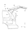
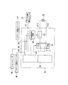
本実施形態に係るパワーリアゲートシステムを搭載した車両100の後部を側面から視たシステム概略図である。It is the system schematic which looked at the rear part of vehicles 100 carrying the power rear gate system concerning this embodiment from the side. 本実施形態に係るパワーリアゲートシステムのブロック構成図である。It is a block block diagram of the power rear gate system which concerns on this embodiment. クロージャーモータ21の常時給電状態を回避するためのパワーリアゲートECU30の第1の構成を示す図である。FIG. 3 is a diagram illustrating a first configuration of a power rear gate ECU 30 for avoiding a constant power supply state of the closure motor 21. クロージャーモータ21の常時給電状態を回避するためのパワーリアゲートECU30の第2の構成(a)及び第3の構成(b)を示す図である。It is a figure which shows the 2nd structure (a) and 3rd structure (b) of power rear gate ECU30 for avoiding the constant power supply state of the closure motor 21. FIG.

以下、本発明の一実施形態について、図面を参照しながら説明する。なお、以下では、本発明に係る車両扉開閉制御装置として、車両扉自動開閉システム、特にリアゲート(車両扉)の自動開閉を行うパワーリアゲートシステムを統括制御するパワーリアゲートECU(Electronic Control Unit)を例示して説明する。  Hereinafter, an embodiment of the present invention will be described with reference to the drawings. In the following, as a vehicle door opening / closing control device according to the present invention, a power rear gate ECU (Electronic Control Unit) that performs overall control of a vehicle door automatic opening / closing system, in particular, a power rear gate system that automatically opens and closes a rear gate (vehicle door) is illustrated. To explain.

図1は、本実施形態に係るパワーリアゲートシステムを搭載した車両100の後部を側面から視たシステム概略図である。なお、図中に記載しているXYZ直交座標系のX軸は車両100の長さ方向を、Y軸は車両100の幅方向を、Z軸は車両100の高さ方向を示している。また、図2は、本実施形態に係るパワーリアゲートシステムのブロック構成図である。  FIG. 1 is a system schematic diagram in which a rear portion of a vehicle 100 equipped with a power rear gate system according to the present embodiment is viewed from the side. Note that the X-axis of the XYZ orthogonal coordinate system shown in the figure indicates the length direction of the vehicle 100, the Y-axis indicates the width direction of the vehicle 100, and the Z-axis indicates the height direction of the vehicle 100. FIG. 2 is a block diagram of the power rear gate system according to the present embodiment.

図1に示すように、本実施形態に係るパワーリアゲートシステムは、車両100のルーフ101の後端部にヒンジ機構102を介して上下に開閉自在に連結されたリアゲート103を、一定条件下でユーザによるスイッチ操作或いはリモコン操作が為された場合に自動的に開閉するシステムである。また、リアゲート103は、手動で開閉することも可能である。  As shown in FIG. 1, the power rear gate system according to the present embodiment includes a rear gate 103 connected to a rear end portion of a roof 101 of a vehicle 100 via a hinge mechanism 102 so as to be opened and closed up and down under a certain condition. This is a system that automatically opens and closes when a switch operation or remote control operation is performed. The rear gate 103 can be manually opened and closed.

なお、手動或いは自動によるリアゲート103の開放動作を補助するために、車両100のリアピラー105とリアゲート103との間には、リアゲート103に対して開方向の押し上げ力を付勢するダンパー104が設けられている。このダンパー104は、車両100の幅方向に対して左右に1本ずつ設けられている。  In order to assist manual or automatic opening operation of the rear gate 103, a damper 104 is provided between the rear pillar 105 and the rear gate 103 of the vehicle 100 to urge the rear gate 103 in the opening direction. ing. One damper 104 is provided on each side of the width direction of the vehicle 100.

リアピラー105の内側には、リアゲートモータ11及び該リアゲートモータ11の回転動作をリアゲート103の開閉動作に変換する機械要素12、13、14、15から成るリアゲート駆動ユニット10が設けられている。  Inside the rear pillar 105, there is provided a rear gate motor 11 and a rear gate drive unit 10 including mechanical elements 12, 13, 14, and 15 that convert the rotation operation of the rear gate motor 11 into an opening / closing operation of the rear gate 103.

リアゲートモータ11は、後述のパワーリアゲートECU30から供給される駆動電流に応じて回転するDCモータである。機械要素12は、リアピラー105の内側にZ軸から後方へ向かって一定角度傾斜した状態で固定されたガイドレールである。機械要素13は、ガイドレール12に沿って昇降自在(往復自在)に装着されたラックギアである。  The rear gate motor 11 is a DC motor that rotates according to a drive current supplied from a power rear gate ECU 30 described later. The machine element 12 is a guide rail that is fixed inside the rear pillar 105 in a state inclined at a certain angle from the Z axis toward the rear. The machine element 13 is a rack gear mounted so as to be movable up and down (reciprocating) along the guide rail 12.

機械要素14は、一端がラックギア13の上端部にY軸周りに回動自在に連結され、且つ他端がリアゲート103の所定位置にY軸周りに回動自在に連結された棒状のアームである。機械要素15は、リアゲートモータ11の回転軸の回転動作をラックギア13の昇降運動(ガイドレール12上の往復運動)に変換するピニオンギア等の各種ギア群を内蔵するギアボックスである。  The mechanical element 14 is a rod-shaped arm having one end connected to the upper end of the rack gear 13 so as to be rotatable about the Y axis and the other end connected to a predetermined position of the rear gate 103 so as to be rotatable about the Y axis. . The mechanical element 15 is a gear box that incorporates various gear groups such as a pinion gear that converts the rotation operation of the rotating shaft of the rear gate motor 11 into the lifting and lowering movement of the rack gear 13 (reciprocating movement on the guide rail 12).

これらの機械要素12、13、14、15によって、リアゲートモータ11の正転時にはラックギア13がガイドレール12に沿って上昇し、アーム15による押し上げ力がリアゲート103に付加されてリアゲート103の開放動作が実現される。一方、リアゲートモータ11の逆転時にはラックギア13がガイドレール12に沿って下降し、アーム15による引き下げ力がリアゲート103に付加されてリアゲート103の閉鎖動作が実現される。  By these mechanical elements 12, 13, 14, and 15, the rack gear 13 is raised along the guide rail 12 during the forward rotation of the rear gate motor 11, and the pushing force by the arm 15 is applied to the rear gate 103, thereby opening the rear gate 103. Realized. On the other hand, when the rear gate motor 11 rotates in the reverse direction, the rack gear 13 descends along the guide rail 12, and a pulling force by the arm 15 is applied to the rear gate 103 to realize the closing operation of the rear gate 103.

なお、このギアボックス15内には、後述のパワーリアゲートECU30による制御に応じてリアゲートモータ11の回転軸と後段の各種ギア群(図2中の符号16)との機械的な接続を切断するクラッチ機構(図2中の符号17)が設けられている。また、このギアボックス15内には、リアゲートモータ11の回転角度を検出するホールセンサ等の角度センサ(図2中の符号18)も設けられている。  In this gear box 15, there is a clutch that disconnects the mechanical connection between the rotating shaft of the rear gate motor 11 and the various gear groups in the subsequent stage (reference numeral 16 in FIG. 2) in accordance with control by a power rear gate ECU 30 described later. A mechanism (reference numeral 17 in FIG. 2) is provided. In addition, an angle sensor (reference numeral 18 in FIG. 2) such as a hall sensor that detects the rotation angle of the rear gate motor 11 is also provided in the gear box 15.

リアゲート103の下端中央部には、リアゲート103のラッチ状態をハーフラッチ状態(ほぼリアゲート103が閉じられているが、完全に車体のストライカに対してラッチされていない状態:半ドア状態)からフルラッチ状態(リアゲート103が車体のストライカに対して完全にラッチされた状態:全閉状態)へ自動的に切替えるクロージャーユニット20が設けられている。  At the center of the lower end of the rear gate 103, the latch state of the rear gate 103 is changed from the half latch state (the rear gate 103 is almost closed but not completely latched with respect to the striker of the vehicle body: the half door state) to the full latch state. A closure unit 20 that automatically switches to a state where the rear gate 103 is completely latched with respect to the striker of the vehicle body: a fully closed state is provided.

このクロージャーユニット20は、図2に示すように、クロージャーモータ21、ラッチ機構22及びラッチ状態検出スイッチ23を備えている。クロージャーモータ21は、後述のパワーリアゲートECU30から供給される駆動電流に応じて回転するDCモータである。ラッチ機構22は、クロージャーモータ21の回転動作をリアゲート103のラッチ状態の切替動作に変換する機械要素から構成されている。  As shown in FIG. 2, the closure unit 20 includes a closure motor 21, a latch mechanism 22, and a latch state detection switch 23. The closure motor 21 is a DC motor that rotates in accordance with a drive current supplied from a power rear gate ECU 30 described later. The latch mechanism 22 includes a mechanical element that converts the rotation operation of the closure motor 21 into the latch state switching operation of the rear gate 103.

このラッチ機構22は、クロージャーモータ21の正転時には、リアゲート103をハーフラッチ状態からフルラッチ状態へ切替え、クロージャーモータ21の逆転時には、リアゲート103をフルラッチ状態からハーフラッチ状態へ切替える。ラッチ状態検出スイッチ23は、リアゲート103のラッチ状態(ハーフラッチ状態か、或いはフルラッチ状態か)を検出するスイッチ群であり、具体的にはラッチスイッチ、カーテシスイッチ、中立状態スイッチ等である。  The latch mechanism 22 switches the rear gate 103 from the half latched state to the full latched state when the closure motor 21 is rotating forward, and switches the rear gate 103 from the full latched state to the half latched state when the closure motor 21 is reversely rotated. The latch state detection switch 23 is a switch group that detects the latch state (half latch state or full latch state) of the rear gate 103, and specifically includes a latch switch, a courtesy switch, a neutral state switch, and the like.

リアゲート駆動ユニット10の下部には、車両100の所定位置に設置された各種スイッチやセンサ或いは他の車載ユニット(いずれも図1では図示省略)から得られる情報を基に、リアゲート駆動ユニット10及びクロージャーユニット20を制御する(つまりリアゲート103の自動開閉制御を行う)パワーリアゲートECU30が設置されている。   A rear gate drive unit 10 and a closure are provided below the rear gate drive unit 10 based on information obtained from various switches and sensors installed at predetermined positions of the vehicle 100 or other in-vehicle units (none of which are shown in FIG. 1). A power rear gate ECU 30 that controls the unit 20 (that is, performs automatic opening / closing control of the rear gate 103) is installed.

具体的には、このパワーリアゲートECU30は、図2に示すように、電源回路31、リアゲートモータ駆動回路32、クロージャーモータ駆動回路33、クラッチ駆動回路34、LIN(Local Interconnect Network) やCAN(Controller Area Network)等の車両通信レシーバ35及びマイコン36を基本的な構成要素として備えている。  Specifically, as shown in FIG. 2, the power rear gate ECU 30 includes a power supply circuit 31, a rear gate motor drive circuit 32, a closure motor drive circuit 33, a clutch drive circuit 34, a LIN (Local Interconnect Network) and a CAN (Controller Area). A vehicle communication receiver 35 such as a network) and a microcomputer 36 are provided as basic components.

また、パワーリアゲートECU30は、外部接続端子として、第1電源端子P1、第2電源端子P2、グランド端子P3、第1入力端子P4、第2入力端子P5、第3入力端子P6、第4入力端子P7、第5入力端子P8、第6入力端子P9、第7入力端子P10、第1出力端子P11、第2出力端子P12、第3出力端子P13、第4出力端子P14、第5出力端子P15及び通信線接続端子P16を備えている。  Further, the power rear gate ECU 30 includes, as external connection terminals, a first power terminal P1, a second power terminal P2, a ground terminal P3, a first input terminal P4, a second input terminal P5, a third input terminal P6, and a fourth input terminal. P7, fifth input terminal P8, sixth input terminal P9, seventh input terminal P10, first output terminal P11, second output terminal P12, third output terminal P13, fourth output terminal P14, fifth output terminal P15, and A communication line connection terminal P16 is provided.

第1電源端子P1は、車両100に搭載されたバッテリ41の正極端子と第1ヒューズ42を介して接続されている。第2電源端子P2は、上記バッテリ41の正極端子と、イグニションスイッチ(IGスイッチ)43及び第2ヒューズ44を介して接続されている。グランド端子P3は、上記バッテリ41の負極端子と接続されている。なお、バッテリ41の負極端子は車体アースされている。  The first power supply terminal P <b> 1 is connected to the positive terminal of the battery 41 mounted on the vehicle 100 via the first fuse 42. The second power supply terminal P <b> 2 is connected to the positive terminal of the battery 41 through an ignition switch (IG switch) 43 and a second fuse 44. The ground terminal P3 is connected to the negative terminal of the battery 41. The negative terminal of the battery 41 is grounded on the vehicle body.

電源回路31の入力端子は第1電源端子P1と接続され、出力端子はマイコン36と接続されている。この電源回路31は、例えばDC/DCコンバータであり、第1電源端子P1を介してバッテリ41から供給されるバッテリ電源電圧VPB(例えば12V)を、マイコン36等の低電圧回路の駆動に必要な内部電源電圧Vdd(例えば3.3V〜5V)に変換する。この内部電源電圧Vddは、マイコン36に供給されると共に、共通のVddラインを介してその他の低電圧回路に供給される。  The input terminal of the power supply circuit 31 is connected to the first power supply terminal P1, and the output terminal is connected to the microcomputer 36. The power supply circuit 31 is, for example, a DC / DC converter, and a battery power supply voltage VPB (for example, 12V) supplied from the battery 41 via the first power supply terminal P1 is necessary for driving a low voltage circuit such as the microcomputer 36. It converts into internal power supply voltage Vdd (for example, 3.3V-5V). The internal power supply voltage Vdd is supplied to the microcomputer 36 and is also supplied to other low voltage circuits through a common Vdd line.

また、第1電源端子P1を介してバッテリ41から供給されるバッテリ電源電圧VPBは、共通のVPBラインを介してリアゲートモータ駆動回路32、クロージャーモータ駆動回路33及びクラッチ駆動回路34等に供給されている。また、グランド端子P3(つまりバッテリ41の負極端子)はパワーリアゲートECU30内の各電子部品に共通のGNDラインと接続されている。なお、第2電源端子P2はマイコン36と接続されており、マイコン36は第2電源端子P2の電圧を監視することで、IGスイッチ43のオン/オフ状態を認識可能となっている。  The battery power supply voltage VPB supplied from the battery 41 via the first power supply terminal P1 is supplied to the rear gate motor drive circuit 32, the closure motor drive circuit 33, the clutch drive circuit 34, etc. via the common VPB line. Yes. The ground terminal P3 (that is, the negative terminal of the battery 41) is connected to a GND line common to each electronic component in the power rear gate ECU 30. The second power supply terminal P2 is connected to the microcomputer 36, and the microcomputer 36 can recognize the on / off state of the IG switch 43 by monitoring the voltage of the second power supply terminal P2.

第1入力端子P4は、運転席側に設置されたメインスイッチ45と接続されている。このメインスイッチ45は、第1入力端子P4を介してマイコン36と接続されており、そのオン/オフ状態によって、リアゲート103の自動開閉制御が許可されている状態か否かをマイコン36に認識させるためのスイッチである。  The first input terminal P4 is connected to a main switch 45 installed on the driver's seat side. The main switch 45 is connected to the microcomputer 36 via the first input terminal P4, and makes the microcomputer 36 recognize whether or not the automatic opening / closing control of the rear gate 103 is permitted depending on the on / off state. It is a switch for.

第2入力端子P5は、運転席側に設置されたリアゲート開閉スイッチ46と接続されている。このリアゲート開閉スイッチ46は、第2入力端子P5を介してマイコン36と接続されており、そのオン/オフ状態によって、ユーザによるリアゲート103の開放操作が為されたか、或いは閉鎖操作が為されたかをマイコン38に認識させるためのスイッチである。  The second input terminal P5 is connected to a rear gate opening / closing switch 46 installed on the driver's seat side. The rear gate opening / closing switch 46 is connected to the microcomputer 36 via the second input terminal P5, and it is determined whether the rear gate 103 is opened or closed by the user depending on the on / off state. This is a switch for causing the microcomputer 38 to recognize.

第3入力端子P6は、パワーリアゲート駆動ユニット10に内蔵された角度センサ18と接続されている。つまり、角度センサ18の出力信号(リアゲートモータ11の回転角度に応じた信号)は、第3入力端子P6を介してマイコン36に入力される。第4入力端子P7は、クロージャーユニット20に内蔵されたラッチ状態検出スイッチ23と接続されている。ラッチ状態検出スイッチ23は、第4入力端子P7を介してマイコン36と接続されており、そのオン/オフ状態によって、リアゲート103がハーフラッチ状態か、フルラッチ状態かをマイコン36に認識させるためのスイッチである。  The third input terminal P6 is connected to the angle sensor 18 built in the power rear gate drive unit 10. That is, an output signal from the angle sensor 18 (a signal corresponding to the rotation angle of the rear gate motor 11) is input to the microcomputer 36 via the third input terminal P6. The fourth input terminal P7 is connected to a latch state detection switch 23 built in the closure unit 20. The latch state detection switch 23 is connected to the microcomputer 36 via the fourth input terminal P7, and is a switch for causing the microcomputer 36 to recognize whether the rear gate 103 is in the half latch state or the full latch state depending on the on / off state. It is.

第5入力端子P8は、リアゲート103に設置されたリアゲート開放スイッチ47と接続されている。このリアゲート開放スイッチ47は、第5入力端子P8を介してマイコン36と接続されており、そのオン/オフ状態によって、ユーザによるリアゲート103の開放操作が為されたことをマイコン36に認識させるためのスイッチである。  The fifth input terminal P8 is connected to a rear gate opening switch 47 provided on the rear gate 103. The rear gate opening switch 47 is connected to the microcomputer 36 via the fifth input terminal P8, and allows the microcomputer 36 to recognize that the user has opened the rear gate 103 depending on the on / off state. Switch.

第6入力端子P9は、リアゲート103に設置されたリアゲート閉鎖スイッチ48と接続されている。このリアゲート閉鎖スイッチ48は、第6入力端子P9を介してマイコン36と接続されており、そのオン/オフ状態によって、ユーザによるリアゲート103の閉鎖操作が為されたことをマイコン36に認識させるためのスイッチである。  The sixth input terminal P <b> 9 is connected to a rear gate closing switch 48 installed on the rear gate 103. The rear gate closing switch 48 is connected to the microcomputer 36 via the sixth input terminal P9, and makes the microcomputer 36 recognize that the user has closed the rear gate 103 depending on the on / off state. Switch.

第7入力端子P10は、リアゲート103に設置されたタッチセンサ49と接続されている。このタッチセンサ49は、第7入力端子P10を介してマイコン36と接続されており、そのオン/オフ状態によって、リアゲート103の閉動作中に、リアゲート103と車体との間に挟み込みが発生したか否かをマイコン36に認識させるためのセンサスイッチである。  The seventh input terminal P <b> 10 is connected to a touch sensor 49 installed on the rear gate 103. The touch sensor 49 is connected to the microcomputer 36 via the seventh input terminal P10. Whether the touch sensor 49 is caught between the rear gate 103 and the vehicle body during the closing operation of the rear gate 103 due to the on / off state. It is a sensor switch for making the microcomputer 36 recognize whether or not.

第1出力端子P11はリアゲートモータ11の正極端子と接続され、第2出力端子P12はリアゲートモータ11の負極端子と接続されている。リアゲートモータ駆動回路32は、マイコン36から供給されるPWM(Pulse Width Modulation)信号によって個別にオン/オフ制御される2つのスイッチ素子32a、32bを備えている。  The first output terminal P11 is connected to the positive terminal of the rear gate motor 11, and the second output terminal P12 is connected to the negative terminal of the rear gate motor 11. The rear gate motor drive circuit 32 includes two switch elements 32 a and 32 b that are individually controlled to be turned on / off by a PWM (Pulse Width Modulation) signal supplied from the microcomputer 36.

スイッチ素子32aは、オン状態時にVPBライン(12Vライン)と第1出力端子P11(つまりリアゲートモータ11の正極端子)とを接続し、オフ状態時にGNDラインと第1出力端子P11とを接続する。スイッチ素子32bは、オン状態時にVPBラインと第2出力端子P12(つまりリアゲートモータ11の負極端子)とを接続し、オフ状態時にGNDラインと第2出力端子P12とを接続する。  The switch element 32a connects the VPB line (12V line) and the first output terminal P11 (that is, the positive terminal of the rear gate motor 11) in the on state, and connects the GND line and the first output terminal P11 in the off state. The switch element 32b connects the VPB line and the second output terminal P12 (that is, the negative terminal of the rear gate motor 11) in the on state, and connects the GND line and the second output terminal P12 in the off state.

つまり、スイッチ素子32bをオフ状態に維持したままで、スイッチ素子32aのオン/オフ状態をPWM制御すると、リアゲートモータ11の正極端子から負極端子へデューティ比に応じた駆動電流が流れて、リアゲートモータ11は正転動作する。一方、スイッチ素子32aをオフ状態に維持したままで、スイッチ素子32bのオン/オフ状態をPWM制御すると、リアゲートモータ11の負極端子から正極端子へデューティ比に応じた駆動電流が流れて、リアゲートモータ11は逆転動作する。   That is, if the on / off state of the switch element 32a is PWM controlled while the switch element 32b is maintained in the off state, a drive current according to the duty ratio flows from the positive terminal to the negative terminal of the rear gate motor 11, and the rear gate motor 11 rotates forward. On the other hand, when the on / off state of the switch element 32b is PWM controlled while the switch element 32a is maintained in the off state, a drive current corresponding to the duty ratio flows from the negative terminal to the positive terminal of the rear gate motor 11, and the rear gate motor 11 performs reverse operation.

第3出力端子P13はクロージャーモータ21の正極端子と接続され、第4出力端子P14はクロージャーモータ21の負極端子と接続されている。クロージャーモータ駆動回路33は、マイコン36から供給されるスイッチ制御信号によって個別にオン/オフ制御される2つのスイッチ素子33a、33bを備えている。   The third output terminal P13 is connected to the positive terminal of the closure motor 21, and the fourth output terminal P14 is connected to the negative terminal of the closure motor 21. The closure motor drive circuit 33 includes two switch elements 33 a and 33 b that are individually controlled to be turned on / off by a switch control signal supplied from the microcomputer 36.

スイッチ素子33aは、オン状態時にVPBラインと第3出力端子P13(つまりクロージャーモータ21の正極端子)とを接続し、オフ状態時にGNDラインと第3出力端子P13とを接続する。スイッチ素子33bは、オン状態時にVPBラインと第4出力端子P14(つまりクロージャーモータ21の負極端子)とを接続し、オフ状態時にGNDラインと第4出力端子P14とを接続する。   The switch element 33a connects the VPB line and the third output terminal P13 (that is, the positive terminal of the closure motor 21) when in the on state, and connects the GND line and the third output terminal P13 when in the off state. The switch element 33b connects the VPB line and the fourth output terminal P14 (that is, the negative terminal of the closure motor 21) when in the on state, and connects the GND line and the fourth output terminal P14 when in the off state.

つまり、スイッチ素子33aをオン状態に及びスイッチ素子33bをオフ状態に制御すると、クロージャーモータ21の正極端子から負極端子へバッテリ電源電圧VPBに応じた駆動電流が流れてクロージャーモータ21は正転動作する。一方、スイッチ素子33aをオフ状態に及びスイッチ素子33bをオン状態に制御すると、クロージャーモータ21の負極端子から正極端子へバッテリ電源電圧VPBに応じた駆動電流が流れてクロージャーモータ21は逆転動作する。   That is, when the switch element 33a is controlled to be in the on state and the switch element 33b is controlled to be in the off state, a drive current corresponding to the battery power supply voltage VPB flows from the positive terminal to the negative terminal of the closure motor 21, so . On the other hand, when the switch element 33a is controlled to be turned off and the switch element 33b is controlled to be turned on, a drive current corresponding to the battery power supply voltage VPB flows from the negative terminal to the positive terminal of the closure motor 21, so that the closure motor 21 performs a reverse operation.

第5出力端子P15は、リアゲート駆動ユニット10に内蔵されたクラッチ機構17と接続されている。クラッチ駆動回路34は、マイコン36から供給されるクラッチ制御信号によってオン/オフ制御されるスイッチ素子34aを備えている。このスイッチ素子34aは、オン状態時にVPBラインと第5出力端子P15(つまりクラッチ機構17)とを接続し、オフ状態時にGNDラインと第5出力端子P15とを接続する。
つまり、スイッチ素子34aのオン状態時に、クラッチ機構17に駆動電流が供給されて、リアゲートモータ11の回転軸と後段の各種ギア群16とが機械的に接続される。
The fifth output terminal P15 is connected to the clutch mechanism 17 built in the rear gate drive unit 10. The clutch drive circuit 34 includes a switch element 34 a that is on / off controlled by a clutch control signal supplied from the microcomputer 36. The switch element 34a connects the VPB line and the fifth output terminal P15 (that is, the clutch mechanism 17) when in the on state, and connects the GND line and the fifth output terminal P15 when in the off state.
That is, when the switch element 34a is in the ON state, a drive current is supplied to the clutch mechanism 17, and the rotating shaft of the rear gate motor 11 and the various gear groups 16 at the subsequent stage are mechanically connected.

通信線接続端子P16は、通信バス50を介して他の車載ユニット(図示省略)と接続されている。車両通信レシーバ35は、通信線接続端子P16とマイコン36との間に設けられており、LINプロトコル或いはCANプロトコルに準拠した通信をマイコン36と他の車載ユニットとの間で行う通信インターフェースである。   The communication line connection terminal P16 is connected to another in-vehicle unit (not shown) via the communication bus 50. The vehicle communication receiver 35 is provided between the communication line connection terminal P16 and the microcomputer 36, and is a communication interface that performs communication based on the LIN protocol or the CAN protocol between the microcomputer 36 and other vehicle-mounted units.

マイコン36(制御部)は、ROM及びRAM等のメモリ、CPUコア、CPUリセット回路、入出力インターフェースなどが一体的に組み込まれたマイクロコントローラであり、リアゲート103の自動開閉制御の中心を担うものである。
具体的には、このマイコン36は、メインスイッチ45、リアゲート開閉スイッチ46、リアゲート開放スイッチ47、リアゲート閉鎖スイッチ48、タッチセンサ49及びラッチ状態検出スイッチ23のオン/オフ状態と、角度センサ18の出力信号と、車両通信レシーバ35を介して他の車載ユニットから受信した車両情報とに基づいて、リアゲートモータ駆動回路32、クロージャーモータ駆動回路33及びクラッチ駆動回路34を制御する。なお、正確には、リアゲート103の自動開閉制御は、マイコン36に内蔵されたCPUが、ROMに記憶されている制御プログラムに従って実行するものである。
The microcomputer 36 (control unit) is a microcontroller in which memories such as a ROM and a RAM, a CPU core, a CPU reset circuit, an input / output interface and the like are integrated, and plays a central role in automatic opening / closing control of the rear gate 103. is there.
Specifically, the microcomputer 36 includes an on / off state of the main switch 45, the rear gate opening / closing switch 46, the rear gate opening switch 47, the rear gate closing switch 48, the touch sensor 49 and the latch state detection switch 23, and the output of the angle sensor 18. Based on the signal and vehicle information received from another vehicle-mounted unit via the vehicle communication receiver 35, the rear gate motor drive circuit 32, the closure motor drive circuit 33, and the clutch drive circuit 34 are controlled. To be precise, the automatic opening / closing control of the rear gate 103 is executed by a CPU built in the microcomputer 36 according to a control program stored in the ROM.

以上が本実施形態におけるパワーリアゲートECU30の基本的な構成であるが、図2からわかるように、クロージャーモータ駆動回路33が故障して、スイッチ素子33aがオン状態に固着すると、クロージャーモータ21が常時給電状態になり、予期せぬタイミングでリアゲート103のラッチが解除されて半ドア状態となる可能性がある。以下では、図3及び図4を参照しながら、クロージャーモータ21の常時給電状態を回避するための構成について説明する。なお、以下では3種類の構成について説明するが、これらのいずれを採用しても構わない。   The above is the basic configuration of the power rear gate ECU 30 in the present embodiment. As can be seen from FIG. 2, when the closure motor drive circuit 33 breaks down and the switch element 33a is fixed in the ON state, the closure motor 21 is always turned on. There is a possibility that the power supply state is entered, and the latch of the rear gate 103 is released at an unexpected timing, resulting in a half-door state. Below, the structure for avoiding the constant power supply state of the closure motor 21 is demonstrated, referring FIG.3 and FIG.4. In the following, three types of configurations will be described, but any of these may be adopted.

<クロージャーモータ21の常時給電状態を回避するための第1の構成>
図3は、クロージャーモータ21の常時給電状態を回避するためのパワーリアゲートECU30の第1の構成を示す図である。なお、以下では、図2と重複する構成要素に同一符号を付して説明を省略する。また、図3では、説明の便宜上、クロージャーモータ21の常時給電状態を回避するための代表的な構成要素のみを示し、他の説明不要な構成要素については省略している。
<First Configuration for Avoiding the Constant Power Supply State of the Closure Motor 21>
FIG. 3 is a diagram showing a first configuration of the power rear gate ECU 30 for avoiding the constant power supply state of the closure motor 21. In addition, below, the same code | symbol is attached | subjected to the component which overlaps with FIG. 2, and description is abbreviate | omitted. Further, in FIG. 3, for the sake of convenience of explanation, only representative components for avoiding the constant power supply state of the closure motor 21 are shown, and other components that do not require explanation are omitted.

図3に示すように、パワーリアゲートECU30の第1の構成では、クロージャーモータ21に接続された第3出力端子P13(外部接続端子)と、クロージャーモータ駆動回路33のスイッチ素子33aとの間の電流経路に電流遮断スイッチ37が介挿されていると共に、マイコン36とは別に、ハードウェア処理によって、電流遮断スイッチ37を、一定条件下でリアゲート103の開放操作が為された場合にオフからオンに制御する制御論理回路38が設けられている。   As shown in FIG. 3, in the first configuration of the power rear gate ECU 30, the current between the third output terminal P <b> 13 (external connection terminal) connected to the closure motor 21 and the switch element 33 a of the closure motor drive circuit 33. A current cut-off switch 37 is inserted in the path, and the current cut-off switch 37 is switched from OFF to ON when the rear gate 103 is opened under a certain condition by hardware processing separately from the microcomputer 36. A control logic circuit 38 for controlling is provided.

一方、マイコン36は、ソフトウェア処理によって、一定条件下でリアゲート103の開放操作が為された場合に、クロージャーモータ21が正転動作するよう、つまりリアゲート103がラッチ解除されるよう、クロージャーモータ駆動回路33(スイッチ素子33a、33b)を制御するものである。   On the other hand, the microcomputer 36 has a closure motor drive circuit so that when the rear gate 103 is opened under a certain condition by software processing, the closure motor 21 rotates forward, that is, the rear gate 103 is unlatched. 33 (switch elements 33a and 33b) are controlled.

なお、制御論理回路38は、マイコン36と同様に、メインスイッチ45、リアゲート開閉スイッチ46、リアゲート開放スイッチ47及びラッチ状態検出スイッチ23と接続されていると共に、マイコン36からリモコンによるリアゲート103の開放操作が為されたことを示す信号が入力される。   The control logic circuit 38 is connected to the main switch 45, the rear gate opening / closing switch 46, the rear gate opening switch 47, and the latch state detection switch 23, as well as the microcomputer 36, and the microcomputer 36 is used to open the rear gate 103 by a remote controller. A signal indicating that has been made is input.

このような第1の構成におけるパワーリアゲートECU30のリアゲート開放時の動作は以下の通りである。マイコン36は、メインスイッチ45がオン状態(リアゲート103の自動開閉制御が許可されている状態)で、且つリアゲート103がフルラッチ状態(全閉状態)という条件下で、運転席のリアゲート開閉スイッチ46或いはリアゲート103のリアゲート開放スイッチ47がオン操作されるか、または他の車載ユニットからリモコンによるリアゲート103の開放操作が為されたことを示す情報を受信した場合に、クロージャーモータ駆動回路33のスイッチ素子33aをオンに、スイッチ素子33bをオフに制御する。   The operation of the power rear gate ECU 30 in such a first configuration when the rear gate is opened is as follows. The microcomputer 36 has a rear gate opening / closing switch 46 in the driver's seat under the condition that the main switch 45 is in an on state (a state in which automatic opening / closing control of the rear gate 103 is permitted) and the rear gate 103 is in a fully latched state (fully closed state). When the rear gate opening switch 47 of the rear gate 103 is turned on or information indicating that the rear gate 103 is opened by a remote controller is received from another in-vehicle unit, the switch element 33a of the closure motor drive circuit 33 is received. Is turned on and the switch element 33b is turned off.

一方、制御論理回路38は、メインスイッチ45がオン状態で、且つリアゲート103がフルラッチ状態という条件下で、運転席のリアゲート開閉スイッチ46或いはリアゲート103のリアゲート開放スイッチ47がオン操作されるか、またはマイコン36からリモコンによるリアゲート103の開放操作が為されたことを示す信号が入力された場合に、電流遮断スイッチ37をオフからオンに制御する。
これにより、クロージャーモータ21の正極端子から負極端子へバッテリ電源電圧VPBに応じた駆動電流が流れてクロージャーモータ21が正転動作し、リアゲート103はラッチ解除される。
On the other hand, under the condition that the main switch 45 is in the on state and the rear gate 103 is in the fully latched state, the control logic circuit 38 turns on the rear gate opening / closing switch 46 of the driver seat or the rear gate opening switch 47 of the rear gate 103, or When a signal indicating that the rear gate 103 is opened by the remote controller is input from the microcomputer 36, the current cutoff switch 37 is controlled from OFF to ON.
As a result, a drive current corresponding to the battery power supply voltage VPB flows from the positive terminal to the negative terminal of the closure motor 21 so that the closure motor 21 rotates forward, and the rear gate 103 is released from the latch.

マイコン36は、ラッチ状態検出スイッチ23のオン/オフ状態を基に、ラッチ解除が完了したことを検知すると(ハーフラッチ状態を検知すると)、クロージャーモータ駆動回路33のスイッチ素子33aをオンからオフに制御する。一方、制御論理回路38も、ラッチ状態検出スイッチ23のオン/オフ状態を基に、ラッチ解除が完了したことを検知すると、電流遮断スイッチ37をオンからオフに制御する。なお、ラッチ状態検出スイッチ23からのラッチ解除信号をマイコン36が判断し、制御論理回路38に入力を与えて電流遮断スイッチ37をオフさせることも可能である。
これにより、クロージャーモータ21には駆動電流が流れなくなり、クロージャーモータ21は停止する。
When the microcomputer 36 detects that the latch release is completed based on the ON / OFF state of the latch state detection switch 23 (detects the half latch state), the microcomputer 36 switches the switch element 33a of the closure motor drive circuit 33 from ON to OFF. Control. On the other hand, when the control logic circuit 38 detects that the latch release is completed based on the ON / OFF state of the latch state detection switch 23, the control logic circuit 38 controls the current cutoff switch 37 from ON to OFF. It is also possible for the microcomputer 36 to determine the latch release signal from the latch state detection switch 23, and to input the control logic circuit 38 to turn off the current cutoff switch 37.
As a result, no drive current flows through the closure motor 21 and the closure motor 21 stops.

以降、マイコン36は、クラッチ駆動回路34のスイッチ素子34aをオン状態にすることでリアゲート駆動ユニット10のクラッチ機構17に駆動電流を供給し、リアゲートモータ11の回転軸と後段の各種ギア群16とを機械的に接続させる。そして、マイコン36は、リアゲートモータ駆動回路32のスイッチ素子32a、32bをPWM制御することでリアゲートモータ11を正転動作させて、リアゲート103を全開位置まで開放させる。なお、この時、マイコン36は、角度センサ18の出力信号を基にリアゲートモータ11の回転速度、つまりリアゲート103の移動速度を把握し、リアゲート103の移動速度が目標速度となるようにリアゲートモータ11をフィードバック制御する。   Thereafter, the microcomputer 36 supplies the drive current to the clutch mechanism 17 of the rear gate drive unit 10 by turning on the switch element 34a of the clutch drive circuit 34, and the rotation shaft of the rear gate motor 11 and the various gear groups 16 in the subsequent stage. Are connected mechanically. Then, the microcomputer 36 controls the switch elements 32a and 32b of the rear gate motor drive circuit 32 by PWM control to cause the rear gate motor 11 to perform normal rotation and open the rear gate 103 to the fully open position. At this time, the microcomputer 36 grasps the rotational speed of the rear gate motor 11, that is, the moving speed of the rear gate 103 based on the output signal of the angle sensor 18, so that the moving speed of the rear gate 103 becomes the target speed. Feedback control.

このように、第1の構成では、リアゲート103の開放時において、クロージャーモータ駆動回路33のスイッチ素子33aと電流遮断スイッチ37とが、それぞれ独立しながらも同じ制御ロジックでオン/オフ制御される。従って、例えば、クロージャーモータ駆動回路33が故障して、スイッチ素子33aがオン状態に固着したとしても、ユーザによる開放操作が為されるまで電流遮断スイッチ37がオフ状態に維持されるため、クロージャーモータ21の常時給電状態を回避することができる。一方、電流遮断スイッチ37が故障してオン状態に固着した場合でも、ユーザによる開放操作が為されるまでクロージャーモータ駆動回路33のスイッチ素子33aがオフ状態に維持されるため、クロージャーモータ21の常時給電状態を回避することができる。   As described above, in the first configuration, when the rear gate 103 is opened, the switch element 33a and the current cutoff switch 37 of the closure motor drive circuit 33 are on / off controlled by the same control logic, although they are independent of each other. Therefore, for example, even if the closure motor drive circuit 33 breaks down and the switch element 33a is fixed in the ON state, the current cutoff switch 37 is maintained in the OFF state until the user performs an opening operation. Thus, the constant power supply state of 21 can be avoided. On the other hand, even when the current cut-off switch 37 breaks down and is fixed in the on state, the switch element 33a of the closure motor drive circuit 33 is maintained in the off state until the user performs an opening operation. The power supply state can be avoided.

以上のように、第1の構成におけるパワーリアゲートECU30によれば、クロージャーモータ駆動回路33或いは電流遮断スイッチ37が故障しても、クロージャーモータ21が常時給電状態となることを回避することができ、その結果、予期せぬタイミングでリアゲート103のラッチが解除されて半ドア状態となることを防ぐことができる。   As described above, according to the power rear gate ECU 30 in the first configuration, even if the closure motor drive circuit 33 or the current cutoff switch 37 breaks down, it is possible to avoid that the closure motor 21 is always in the power supply state. As a result, it is possible to prevent the latch of the rear gate 103 from being released at an unexpected timing and entering a half-door state.

<クロージャーモータ21の常時給電状態を回避するための第2の構成>
図4(a)は、クロージャーモータ21の常時給電状態を回避するためのパワーリアゲートECU30の第2の構成を示す図である。なお、以下では、図2及び図3と重複する構成要素に同一符号を付して説明を省略する。また、図4(a)では、説明の便宜上、クロージャーモータ21の常時給電状態を回避するための代表的な構成要素のみを示し、他の説明不要な構成要素については省略している。
<Second Configuration for Avoiding the Constant Power Supply State of the Closure Motor 21>
FIG. 4A is a diagram showing a second configuration of the power rear gate ECU 30 for avoiding the constant power supply state of the closure motor 21. In addition, below, the same code | symbol is attached | subjected to the component which overlaps with FIG.2 and FIG.3, and description is abbreviate | omitted. In FIG. 4A, for convenience of explanation, only representative components for avoiding the constant power supply state of the closure motor 21 are shown, and other components that do not require explanation are omitted.

図4(a)に示すように、パワーリアゲートECU30の第2の構成では、クロージャーモータ21に接続された第3出力端子P13と、クロージャーモータ駆動回路33のスイッチ素子33aとの間の電流経路に電流遮断スイッチ37が介挿されている。  As shown in FIG. 4A, in the second configuration of the power rear gate ECU 30, the current path between the third output terminal P13 connected to the closure motor 21 and the switch element 33a of the closure motor drive circuit 33 is shown. A current cut-off switch 37 is inserted.

一方、マイコン36は、クロージャーモータ駆動回路33のスイッチ素子33aと電流遮断スイッチ37との間の電流経路の電圧値V1を監視する機能を有しており、一定条件下でリアゲート103の開放操作が為された場合で、且つ上記電圧値V1がクロージャーモータ21の駆動電圧(つまりバッテリ電源電圧VPB)と異なる場合、クロージャーモータ21が正転動作するようクロージャーモータ駆動回路33を制御すると共に、電流遮断スイッチ37をオフからオンに制御する。   On the other hand, the microcomputer 36 has a function of monitoring the voltage value V1 of the current path between the switch element 33a of the closure motor drive circuit 33 and the current cutoff switch 37, and the opening operation of the rear gate 103 can be performed under a certain condition. If the voltage value V1 is different from the drive voltage of the closure motor 21 (that is, the battery power supply voltage VPB), the closure motor drive circuit 33 is controlled so that the closure motor 21 rotates forward and the current is cut off. The switch 37 is controlled from off to on.

このような第2の構成におけるパワーリアゲートECU30のリアゲート開放時の動作は以下の通りである。マイコン36は、メインスイッチ45がオン状態で、且つリアゲート103がフルラッチ状態という条件下で、運転席のリアゲート開閉スイッチ46或いはリアゲート103のリアゲート開放スイッチ47がオン操作されるか、または他の車載ユニットからリモコンによるリアゲート103の開放操作が為されたことを示す情報を受信した場合で、且つ上記電圧値V1がバッテリ電源電圧VPBと異なる場合に、クロージャーモータ駆動回路33のスイッチ素子33aをオンに、スイッチ素子33bをオフに制御すると共に、電流遮断スイッチ37をオフからオンに制御する。
これにより、クロージャーモータ21の正極端子から負極端子へバッテリ電源電圧VPBに応じた駆動電流が流れてクロージャーモータ21が正転動作し、リアゲート103はラッチ解除される。
The operation of the power rear gate ECU 30 in such a second configuration when the rear gate is opened is as follows. When the main switch 45 is in the on state and the rear gate 103 is in the fully latched state, the microcomputer 36 turns on the rear gate opening / closing switch 46 of the driver's seat or the rear gate opening switch 47 of the rear gate 103 or other in-vehicle unit. When the information indicating that the rear gate 103 is opened by the remote controller is received and the voltage value V1 is different from the battery power supply voltage VPB, the switch element 33a of the closure motor drive circuit 33 is turned on. The switch element 33b is controlled to be off and the current cutoff switch 37 is controlled from off to on.
As a result, a drive current corresponding to the battery power supply voltage VPB flows from the positive terminal to the negative terminal of the closure motor 21 so that the closure motor 21 rotates forward, and the rear gate 103 is released from the latch.

マイコン36は、ラッチ状態検出スイッチ23のオン/オフ状態を基に、ラッチ解除が完了したことを検知すると(ハーフラッチ状態を検知すると)、クロージャーモータ駆動回路33のスイッチ素子33aをオンからオフに制御すると共に、電流遮断スイッチ37をオンからオフに制御する。
これにより、クロージャーモータ21には駆動電流が流れなくなり、クロージャーモータ21は停止する。以降の制御は第1の構成と同様なので説明を省略する。
When the microcomputer 36 detects that the latch release is completed based on the ON / OFF state of the latch state detection switch 23 (detects the half latch state), the microcomputer 36 switches the switch element 33a of the closure motor drive circuit 33 from ON to OFF. At the same time, the current cutoff switch 37 is controlled from on to off.
As a result, no drive current flows through the closure motor 21 and the closure motor 21 stops. Since the subsequent control is the same as that of the first configuration, description thereof is omitted.

このように、第2の構成では、電圧値V1がバッテリ電源電圧VPBと異なる場合、つまりクロージャーモータ駆動回路33のスイッチ素子33aが正常な場合に、クロージャーモータ21が正転動作してリアゲート103はラッチ解除される。また、クロージャーモータ駆動回路33が故障して、スイッチ素子33aがオン状態に固着したとしても、ユーザによる開放操作が為されるまで電流遮断スイッチ37がオフ状態に維持されるため、クロージャーモータ21の常時給電状態を回避することができる。   As described above, in the second configuration, when the voltage value V1 is different from the battery power supply voltage VPB, that is, when the switch element 33a of the closure motor drive circuit 33 is normal, the closure motor 21 rotates forward and the rear gate 103 Unlatched. Even if the closure motor drive circuit 33 breaks down and the switch element 33a is fixed in the on state, the current cutoff switch 37 is maintained in the off state until the user performs an opening operation. A constant power supply state can be avoided.

<クロージャーモータ21の常時給電状態を回避するための第3の構成>
図4(b)は、クロージャーモータ21の常時給電状態を回避するためのパワーリアゲートECU30の第3の構成を示す図である。なお、以下では、図4(a)と重複する構成要素に同一符号を付して説明を省略する。また、図4(b)では、説明の便宜上、クロージャーモータ21の常時給電状態を回避するための代表的な構成要素のみを示し、他の説明不要な構成要素については省略している。
<Third Configuration for Avoiding the Constant Power Supply State of the Closure Motor 21>
FIG. 4B is a diagram showing a third configuration of the power rear gate ECU 30 for avoiding the constant power supply state of the closure motor 21. In addition, below, the same code | symbol is attached | subjected to the component which overlaps with Fig.4 (a), and description is abbreviate | omitted. Further, in FIG. 4B, for the sake of convenience of explanation, only representative components for avoiding the constant power supply state of the closure motor 21 are shown, and other components that do not require explanation are omitted.

図4(b)に示すように、パワーリアゲートECU30の第3の構成において第2の構成と異なる点は、マイコン36が第3出力端子P13の電圧値V2を監視する機能を有し、一定条件下でリアゲート103の開放操作が為された場合に、クロージャーモータ21が正転動作するようクロージャーモータ駆動回路33を制御すると共に、電流遮断スイッチ37をオフからオンに制御し、ラッチ解除後に電流遮断スイッチ37をオフに制御しても上記電圧値V2に変化が無い場合には、クロージャーモータ21が停止するようクロージャーモータ駆動回路33を制御する点である。  As shown in FIG. 4B, the third configuration of the power rear gate ECU 30 is different from the second configuration in that the microcomputer 36 has a function of monitoring the voltage value V2 of the third output terminal P13, and a certain condition. When the rear gate 103 is opened below, the closure motor drive circuit 33 is controlled so that the closure motor 21 rotates forward, and the current cut-off switch 37 is controlled from OFF to ON, and the current is cut off after the latch is released. If the voltage value V2 does not change even when the switch 37 is turned off, the closure motor drive circuit 33 is controlled so that the closure motor 21 stops.

このような第3の構成におけるパワーリアゲートECU30のリアゲート開放時の動作は以下の通りである。マイコン36は、メインスイッチ45がオン状態で、且つリアゲート103がフルラッチ状態という条件下で、運転席のリアゲート開閉スイッチ46或いはリアゲート103のリアゲート開放スイッチ47がオン操作されるか、または他の車載ユニットからリモコンによるリアゲート103の開放操作が為されたことを示す情報を受信した場合、クロージャーモータ駆動回路33のスイッチ素子33aをオンに、スイッチ素子33bをオフに制御すると共に、電流遮断スイッチ37をオフからオンに制御する。
これにより、クロージャーモータ21の正極端子から負極端子へバッテリ電源電圧VPBに応じた駆動電流が流れてクロージャーモータ21が正転動作し、リアゲート103はラッチ解除される。
The operation of the power rear gate ECU 30 in such a third configuration when the rear gate is opened is as follows. When the main switch 45 is in the on state and the rear gate 103 is in the fully latched state, the microcomputer 36 turns on the rear gate opening / closing switch 46 of the driver's seat or the rear gate opening switch 47 of the rear gate 103 or other in-vehicle unit. When receiving information indicating that the rear gate 103 has been opened by the remote controller, the switch element 33a of the closure motor drive circuit 33 is controlled to be turned on, the switch element 33b is turned off, and the current cutoff switch 37 is turned off. Control from on to off.
As a result, a drive current corresponding to the battery power supply voltage VPB flows from the positive terminal to the negative terminal of the closure motor 21 so that the closure motor 21 rotates forward, and the rear gate 103 is released from the latch.

そして、マイコン36は、ラッチ状態検出スイッチ23のオン/オフ状態を基に、ラッチ解除が完了したことを検知すると、電流遮断スイッチ37をオフに制御して、上記電圧値V2に変化が無いか否かを監視する。ここで、マイコン36は、ラッチ解除後に電流遮断スイッチ37をオフに制御しても上記電圧値V2に変化が無い場合には、クロージャーモータ駆動回路33のスイッチ素子33aをオンからオフに制御する。
これにより、クロージャーモータ21には駆動電流が流れなくなり、クロージャーモータ21は停止する。以降の制御は第1の構成と同様なので説明を省略する。
クロージャーモータ駆動回路33の制御はスイッチ素子33aをオンからオフにすることでクロージャーモータ21に対し電流遮断することになるが、電流遮断スイッチ37及びスイッチ素子33aをオフにしても電圧値V2がVPB相当の電圧であった場合、スイッチ素子33bをオフすることでクロージャーモータ21への電流供給、具体的にはクロージャーモータ21の動作を停止させることも可能である。
When the microcomputer 36 detects that the latch release has been completed based on the on / off state of the latch state detection switch 23, the microcomputer 36 controls the current cut-off switch 37 to be off, so that there is no change in the voltage value V2. Monitor whether or not. Here, the microcomputer 36 controls the switch element 33a of the closure motor drive circuit 33 from on to off when the voltage value V2 does not change even if the current cut-off switch 37 is turned off after the latch is released.
As a result, no drive current flows through the closure motor 21 and the closure motor 21 stops. Since the subsequent control is the same as that of the first configuration, description thereof is omitted.
The control of the closure motor drive circuit 33 cuts off the current to the closure motor 21 by turning off the switch element 33a, but the voltage value V2 is VPB even if the current cut-off switch 37 and the switch element 33a are turned off. When the voltage is considerable, it is possible to stop the current supply to the closure motor 21, specifically, the operation of the closure motor 21 by turning off the switch element 33 b.

このように、第3の構成では、ラッチ解除後に電流遮断スイッチ37をオフに制御しても上記電圧値V2に変化が無い場合、つまり電流遮断スイッチ37が故障(オン状態に固着)している場合でも、ユーザによる開放操作が為されるまでクロージャーモータ駆動回路33のスイッチ素子33aがオフ状態に維持されるため、クロージャーモータ21の常時給電状態を回避することができる。   As described above, in the third configuration, even when the current cut-off switch 37 is controlled to be turned off after the latch is released, the voltage value V2 does not change, that is, the current cut-off switch 37 is broken (fixed in the on state). Even in this case, the switch element 33a of the closure motor drive circuit 33 is maintained in the OFF state until the user performs an opening operation, so that the constant power supply state of the closure motor 21 can be avoided.

また、第3の構成において、マイコン36がIGスイッチ43のオン/オフ状態を検出する機能を有することを利用して、ラッチ解除後に電流遮断スイッチ37をオフに制御しても電圧値V2に変化が無い場合で、且つIGスイッチ43のオフを検知した場合に、クロージャーモータ21が停止するようクロージャーモータ駆動回路33を制御しても良い。これにより、ユーザが危険を感じてIGスイッチ43のオフにするような場合でも、リアゲート103のラッチ解除を回避することができる。  In the third configuration, the microcomputer 36 has a function of detecting the on / off state of the IG switch 43. Even if the current cutoff switch 37 is controlled to be turned off after the latch is released, the voltage value V2 is changed. The closure motor drive circuit 33 may be controlled so that the closure motor 21 stops when there is no occurrence and when it is detected that the IG switch 43 is turned off. Thereby, even when the user feels danger and turns off the IG switch 43, the latch release of the rear gate 103 can be avoided.

以上、本発明の一実施形態について説明したが、本発明は上記実施形態に限定されず、本発明の趣旨を逸脱しない範囲において実施形態を変更しても良いことは勿論である。
例えば、上記実施形態では、車両扉としてリアゲート103の自動開閉制御を行うパワーリアゲートECU30を例示したが、スライドドアなどの他の車両扉の自動開閉制御を行う車両扉開閉制御装置にも本発明を適用することができる。
As mentioned above, although one Embodiment of this invention was described, this invention is not limited to the said embodiment, Of course, you may change embodiment in the range which does not deviate from the meaning of this invention.
For example, in the above embodiment, the power rear gate ECU 30 that performs automatic opening / closing control of the rear gate 103 is exemplified as the vehicle door, but the present invention is also applied to a vehicle door opening / closing control device that performs automatic opening / closing control of other vehicle doors such as a slide door. Can be applied.

30…パワーリアゲートECU(車両扉開閉制御装置)、10…リアゲート駆動ユニット、20…クロージャーユニット、21…クロージャーモータ、33…クロージャーモータ駆動回路、36…マイコン(制御部)、37…電流遮断スイッチ、38…制御論理回路、41…バッテリ、100…車両、103…リアゲート   DESCRIPTION OF SYMBOLS 30 ... Power rear gate ECU (vehicle door opening / closing control apparatus), 10 ... Rear gate drive unit, 20 ... Closure unit, 21 ... Closure motor, 33 ... Closure motor drive circuit, 36 ... Microcomputer (control part), 37 ... Current interruption switch, 38 ... Control logic circuit, 41 ... Battery, 100 ... Vehicle, 103 ... Rear gate

Claims (5)

車両扉のラッチ解除に使用されるモータを駆動する駆動回路と、一定条件下で前記車両扉の開放操作が為された場合に前記モータの回転によってラッチ解除されるよう前記駆動回路を制御する制御部とを備える車両扉開閉制御装置であって、
前記モータに接続された外部接続端子と前記駆動回路との間の電流経路に電流遮断スイッチが介挿されていることを特徴とする車両扉開閉制御装置。
A drive circuit for driving a motor used for unlatching the vehicle door, and a control for controlling the drive circuit to be unlatched by rotation of the motor when the vehicle door is opened under certain conditions A vehicle door opening / closing control device comprising:
A vehicle door opening / closing control device, wherein a current cutoff switch is inserted in a current path between an external connection terminal connected to the motor and the drive circuit.
前記制御部とは別に設けられ、前記電流遮断スイッチを、前記一定条件下で車両扉の開放操作が為された場合にオフからオンに制御する制御論理回路を備えることを特徴とする請求項1に記載の車両扉開閉制御装置。   2. A control logic circuit that is provided separately from the control unit and controls the current cutoff switch from off to on when a vehicle door opening operation is performed under the certain condition. The vehicle door opening / closing control device according to claim 1. 前記制御部は、前記一定条件下で車両扉の開放操作が為された場合で、且つ前記駆動回路と前記電流遮断スイッチとの間の電流経路の電圧値が前記モータの駆動電圧と異なる場合、前記モータの回転によってラッチ解除されるよう前記駆動回路を制御すると共に、前記電流遮断スイッチをオフからオンに制御することを特徴とする請求項1に記載の車両扉開閉制御装置。   When the vehicle door opening operation is performed under the certain condition and the voltage value of the current path between the drive circuit and the current cutoff switch is different from the drive voltage of the motor, 2. The vehicle door opening / closing control device according to claim 1, wherein the drive circuit is controlled to be unlatched by rotation of the motor, and the current cutoff switch is controlled from OFF to ON. 前記制御部は、前記一定条件下で車両扉の開放操作が為された場合、前記モータの回転によってラッチ解除されるよう前記駆動回路を制御すると共に、前記電流遮断スイッチをオフからオンに制御し、ラッチ解除後に前記電流遮断スイッチをオフに制御しても前記外部接続端子の電圧値に変化が無い場合、前記モータが停止するよう前記駆動回路を制御することを特徴とする請求項1に記載の車両扉開閉制御装置。   The control unit controls the drive circuit so that the latch is released by the rotation of the motor when the opening operation of the vehicle door is performed under the certain condition, and controls the current cutoff switch from OFF to ON. The drive circuit is controlled to stop the motor when the voltage value of the external connection terminal does not change even if the current cut-off switch is turned off after the latch is released. Vehicle door opening and closing control device. 前記制御部は、ラッチ解除後に前記電流遮断スイッチをオフに制御しても前記外部接続端子の電圧値に変化が無い場合で、且つイグニションスイッチのオフを検知した場合に、前記モータが停止するよう前記駆動回路を制御することを特徴とする請求項4に記載の車両扉開閉制御装置。   The control unit is configured to stop the motor when the voltage value of the external connection terminal is not changed even when the current cut-off switch is controlled to be turned off after the latch is released and when the ignition switch is detected to be turned off. The vehicle door opening / closing control device according to claim 4, wherein the drive circuit is controlled.
JP2011072059A 2011-03-29 2011-03-29 Vehicle door opening/closing controller Withdrawn JP2012207392A (en)

Priority Applications (1)

Application Number Priority Date Filing Date Title
JP2011072059A JP2012207392A (en) 2011-03-29 2011-03-29 Vehicle door opening/closing controller

Applications Claiming Priority (1)

Application Number Priority Date Filing Date Title
JP2011072059A JP2012207392A (en) 2011-03-29 2011-03-29 Vehicle door opening/closing controller

Publications (1)

Publication Number Publication Date
JP2012207392A true JP2012207392A (en) 2012-10-25

Family

ID=47187361

Family Applications (1)

Application Number Title Priority Date Filing Date
JP2011072059A Withdrawn JP2012207392A (en) 2011-03-29 2011-03-29 Vehicle door opening/closing controller

Country Status (1)

Country Link
JP (1) JP2012207392A (en)

Cited By (2)

* Cited by examiner, † Cited by third party
Publication number Priority date Publication date Assignee Title
CN106042858A (en) * 2015-04-17 2016-10-26 本田技研工业株式会社 Vehicle
CN114251024A (en) * 2021-12-21 2022-03-29 恩坦华汽车零部件(镇江)有限公司 PWM control-introduced self-closing automobile back door lock

Cited By (4)

* Cited by examiner, † Cited by third party
Publication number Priority date Publication date Assignee Title
CN106042858A (en) * 2015-04-17 2016-10-26 本田技研工业株式会社 Vehicle
JP2016203720A (en) * 2015-04-17 2016-12-08 本田技研工業株式会社 vehicle
CN114251024A (en) * 2021-12-21 2022-03-29 恩坦华汽车零部件(镇江)有限公司 PWM control-introduced self-closing automobile back door lock
CN114251024B (en) * 2021-12-21 2023-03-03 恩坦华汽车零部件(镇江)有限公司 PWM control-introduced self-closing automobile back door lock

Similar Documents

Publication Publication Date Title
JP2012207382A (en) Vehicle door opening/closing controller and vehicle door automatic opening/closing system
US9677315B2 (en) Door opening/closing control device
JP3754285B2 (en) Automatic door opening and closing device
US7941972B2 (en) Powered opening and closing system for vehicle&#39;s door
JP6255631B2 (en) Automotive door closing device
US9617777B2 (en) Vehicle window opening device
JP2013119752A (en) Opening and closing device of vehicle door
US8710773B2 (en) Vehicle window opening and closing control device
JP2015537132A (en) Car door lock
JP5692532B2 (en) Opening and closing body control device for vehicle
CN223707362U (en) Control components for operating a motor vehicle interlocking system and a motor vehicle interlocking system for a motor vehicle.
JP2012206543A (en) Electronic control device
KR20200084046A (en) Method for operating a drive system for vehicle hatch
US10557291B2 (en) Method for controlling a closing process of a vehicle wing and corresponding vehicle closing system
JP2012207392A (en) Vehicle door opening/closing controller
JP4205507B2 (en) Steering lock device
JP2013119751A (en) Opening and closing device of vehicle door
KR20180058297A (en) Vehicle and method of fabrication of vehicle
US6353300B1 (en) Open roof operating method and open roof operation control system
JP2016065398A (en) Door opening-closing control device and vehicle
JP6072546B2 (en) Opening and closing body control device
JP3960328B2 (en) Automatic opening / closing device for vehicle opening / closing member
JP5347247B2 (en) Opening and closing device for vehicle
JP2002240564A (en) Door opening and closing operation device for vehicles
CN112065202B (en) Opening/closing body control device

Legal Events

Date Code Title Description
A300 Withdrawal of application because of no request for examination

Free format text: JAPANESE INTERMEDIATE CODE: A300

Effective date: 20140603