JP2012207655A - Rankine cycle apparatus - Google Patents
Rankine cycle apparatus Download PDFInfo
- Publication number
- JP2012207655A JP2012207655A JP2011186221A JP2011186221A JP2012207655A JP 2012207655 A JP2012207655 A JP 2012207655A JP 2011186221 A JP2011186221 A JP 2011186221A JP 2011186221 A JP2011186221 A JP 2011186221A JP 2012207655 A JP2012207655 A JP 2012207655A
- Authority
- JP
- Japan
- Prior art keywords
- working fluid
- back pressure
- pressure chamber
- introduction
- chamber
- Prior art date
- Legal status (The legal status is an assumption and is not a legal conclusion. Google has not performed a legal analysis and makes no representation as to the accuracy of the status listed.)
- Withdrawn
Links
- 239000012530 fluid Substances 0.000 claims abstract description 202
- 230000007246 mechanism Effects 0.000 claims description 33
- 239000007788 liquid Substances 0.000 claims description 20
- 238000009795 derivation Methods 0.000 claims description 10
- 238000007599 discharging Methods 0.000 claims 1
- 238000003825 pressing Methods 0.000 abstract description 10
- 230000009467 reduction Effects 0.000 abstract description 2
- 230000002708 enhancing effect Effects 0.000 abstract 1
- 239000002131 composite material Substances 0.000 description 36
- 230000002093 peripheral effect Effects 0.000 description 24
- 230000008016 vaporization Effects 0.000 description 23
- 238000004891 communication Methods 0.000 description 21
- 238000009834 vaporization Methods 0.000 description 20
- 238000005192 partition Methods 0.000 description 15
- 238000007789 sealing Methods 0.000 description 10
- 230000000694 effects Effects 0.000 description 9
- 239000006096 absorbing agent Substances 0.000 description 5
- 238000006243 chemical reaction Methods 0.000 description 4
- 239000000498 cooling water Substances 0.000 description 4
- 230000007423 decrease Effects 0.000 description 4
- 239000000463 material Substances 0.000 description 3
- 230000008602 contraction Effects 0.000 description 2
- 239000007789 gas Substances 0.000 description 2
- 238000009434 installation Methods 0.000 description 2
- 239000002918 waste heat Substances 0.000 description 2
- 230000009471 action Effects 0.000 description 1
- 230000008901 benefit Effects 0.000 description 1
- 230000005540 biological transmission Effects 0.000 description 1
- 230000008859 change Effects 0.000 description 1
- 230000006835 compression Effects 0.000 description 1
- 238000007906 compression Methods 0.000 description 1
- 238000001514 detection method Methods 0.000 description 1
- 239000002184 metal Substances 0.000 description 1
- 238000000034 method Methods 0.000 description 1
- 238000012856 packing Methods 0.000 description 1
- 230000000149 penetrating effect Effects 0.000 description 1
- 238000005057 refrigeration Methods 0.000 description 1
- 238000000926 separation method Methods 0.000 description 1
Images

Classifications
-
- F—MECHANICAL ENGINEERING; LIGHTING; HEATING; WEAPONS; BLASTING
- F04—POSITIVE - DISPLACEMENT MACHINES FOR LIQUIDS; PUMPS FOR LIQUIDS OR ELASTIC FLUIDS
- F04C—ROTARY-PISTON, OR OSCILLATING-PISTON, POSITIVE-DISPLACEMENT MACHINES FOR LIQUIDS; ROTARY-PISTON, OR OSCILLATING-PISTON, POSITIVE-DISPLACEMENT PUMPS
- F04C27/00—Sealing arrangements in rotary-piston pumps specially adapted for elastic fluids
- F04C27/005—Axial sealings for working fluid
-
- F—MECHANICAL ENGINEERING; LIGHTING; HEATING; WEAPONS; BLASTING
- F01—MACHINES OR ENGINES IN GENERAL; ENGINE PLANTS IN GENERAL; STEAM ENGINES
- F01K—STEAM ENGINE PLANTS; STEAM ACCUMULATORS; ENGINE PLANTS NOT OTHERWISE PROVIDED FOR; ENGINES USING SPECIAL WORKING FLUIDS OR CYCLES
- F01K25/00—Plants or engines characterised by use of special working fluids, not otherwise provided for; Plants operating in closed cycles and not otherwise provided for
- F01K25/02—Plants or engines characterised by use of special working fluids, not otherwise provided for; Plants operating in closed cycles and not otherwise provided for the fluid remaining in the liquid phase
-
- F—MECHANICAL ENGINEERING; LIGHTING; HEATING; WEAPONS; BLASTING
- F01—MACHINES OR ENGINES IN GENERAL; ENGINE PLANTS IN GENERAL; STEAM ENGINES
- F01C—ROTARY-PISTON OR OSCILLATING-PISTON MACHINES OR ENGINES
- F01C1/00—Rotary-piston machines or engines
- F01C1/02—Rotary-piston machines or engines of arcuate-engagement type, i.e. with circular translatory movement of co-operating members, each member having the same number of teeth or tooth-equivalents
- F01C1/0207—Rotary-piston machines or engines of arcuate-engagement type, i.e. with circular translatory movement of co-operating members, each member having the same number of teeth or tooth-equivalents both members having co-operating elements in spiral form
- F01C1/0215—Rotary-piston machines or engines of arcuate-engagement type, i.e. with circular translatory movement of co-operating members, each member having the same number of teeth or tooth-equivalents both members having co-operating elements in spiral form where only one member is moving
-
- F—MECHANICAL ENGINEERING; LIGHTING; HEATING; WEAPONS; BLASTING
- F04—POSITIVE - DISPLACEMENT MACHINES FOR LIQUIDS; PUMPS FOR LIQUIDS OR ELASTIC FLUIDS
- F04C—ROTARY-PISTON, OR OSCILLATING-PISTON, POSITIVE-DISPLACEMENT MACHINES FOR LIQUIDS; ROTARY-PISTON, OR OSCILLATING-PISTON, POSITIVE-DISPLACEMENT PUMPS
- F04C18/00—Rotary-piston pumps specially adapted for elastic fluids
- F04C18/02—Rotary-piston pumps specially adapted for elastic fluids of arcuate-engagement type, i.e. with circular translatory movement of co-operating members, each member having the same number of teeth or tooth-equivalents
-
- F—MECHANICAL ENGINEERING; LIGHTING; HEATING; WEAPONS; BLASTING
- F04—POSITIVE - DISPLACEMENT MACHINES FOR LIQUIDS; PUMPS FOR LIQUIDS OR ELASTIC FLUIDS
- F04C—ROTARY-PISTON, OR OSCILLATING-PISTON, POSITIVE-DISPLACEMENT MACHINES FOR LIQUIDS; ROTARY-PISTON, OR OSCILLATING-PISTON, POSITIVE-DISPLACEMENT PUMPS
- F04C18/00—Rotary-piston pumps specially adapted for elastic fluids
- F04C18/08—Rotary-piston pumps specially adapted for elastic fluids of intermeshing-engagement type, i.e. with engagement of co-operating members similar to that of toothed gearing
-
- F—MECHANICAL ENGINEERING; LIGHTING; HEATING; WEAPONS; BLASTING
- F04—POSITIVE - DISPLACEMENT MACHINES FOR LIQUIDS; PUMPS FOR LIQUIDS OR ELASTIC FLUIDS
- F04C—ROTARY-PISTON, OR OSCILLATING-PISTON, POSITIVE-DISPLACEMENT MACHINES FOR LIQUIDS; ROTARY-PISTON, OR OSCILLATING-PISTON, POSITIVE-DISPLACEMENT PUMPS
- F04C2240/00—Components
- F04C2240/45—Hybrid prime mover
-
- F—MECHANICAL ENGINEERING; LIGHTING; HEATING; WEAPONS; BLASTING
- F04—POSITIVE - DISPLACEMENT MACHINES FOR LIQUIDS; PUMPS FOR LIQUIDS OR ELASTIC FLUIDS
- F04C—ROTARY-PISTON, OR OSCILLATING-PISTON, POSITIVE-DISPLACEMENT MACHINES FOR LIQUIDS; ROTARY-PISTON, OR OSCILLATING-PISTON, POSITIVE-DISPLACEMENT PUMPS
- F04C23/00—Combinations of two or more pumps, each being of rotary-piston or oscillating-piston type, specially adapted for elastic fluids; Pumping installations specially adapted for elastic fluids; Multi-stage pumps specially adapted for elastic fluids
- F04C23/005—Combinations of two or more pumps, each being of rotary-piston or oscillating-piston type, specially adapted for elastic fluids; Pumping installations specially adapted for elastic fluids; Multi-stage pumps specially adapted for elastic fluids of dissimilar working principle
-
- F—MECHANICAL ENGINEERING; LIGHTING; HEATING; WEAPONS; BLASTING
- F04—POSITIVE - DISPLACEMENT MACHINES FOR LIQUIDS; PUMPS FOR LIQUIDS OR ELASTIC FLUIDS
- F04C—ROTARY-PISTON, OR OSCILLATING-PISTON, POSITIVE-DISPLACEMENT MACHINES FOR LIQUIDS; ROTARY-PISTON, OR OSCILLATING-PISTON, POSITIVE-DISPLACEMENT PUMPS
- F04C23/00—Combinations of two or more pumps, each being of rotary-piston or oscillating-piston type, specially adapted for elastic fluids; Pumping installations specially adapted for elastic fluids; Multi-stage pumps specially adapted for elastic fluids
- F04C23/008—Hermetic pumps
Landscapes
- Engineering & Computer Science (AREA)
- Mechanical Engineering (AREA)
- General Engineering & Computer Science (AREA)
- Chemical & Material Sciences (AREA)
- Combustion & Propulsion (AREA)
- Applications Or Details Of Rotary Compressors (AREA)
- Rotary Pumps (AREA)
- Structures Of Non-Positive Displacement Pumps (AREA)
Abstract
Description
本発明は、作動流体を吐出するポンプと、ポンプから吐出された作動流体と排熱源からの流体との間で熱交換させる熱交換器と、熱交換器で熱交換された作動流体を膨張させて機械的エネルギーを出力する膨張部と、を有する回路を備えるランキンサイクル装置に関する。 The present invention includes a pump that discharges a working fluid, a heat exchanger that exchanges heat between the working fluid discharged from the pump and a fluid from an exhaust heat source, and a working fluid that has been heat-exchanged by the heat exchanger. The present invention relates to a Rankine cycle device including a circuit having an expansion portion that outputs mechanical energy.
ランキンサイクル装置に用いられるスクロール式の膨張部は、駆動軸の回転によって旋回する可動スクロールと、ハウジングに固定された固定スクロールとを備える。可動スクロールの可動側端板には可動側渦巻壁が立設されるとともに、固定スクロールの固定側端板には固定側渦巻壁が立設され、可動側渦巻壁と固定側渦巻壁との間には、膨張室が区画形成されている。そして、熱交換器で熱エネルギーを得た作動流体は、膨張部の吸入室に導入された後、膨張室に導入されて膨張し、この作動流体の膨張による可動スクロールの旋回に伴い機械的エネルギー(駆動力)が出力される。 A scroll-type expansion portion used in the Rankine cycle apparatus includes a movable scroll that revolves by rotation of a drive shaft, and a fixed scroll that is fixed to a housing. A movable-side spiral wall is erected on the movable-side end plate of the movable scroll, and a fixed-side spiral wall is erected on the fixed-side end plate of the fixed scroll, between the movable-side spiral wall and the fixed-side spiral wall. The expansion chamber is partitioned. The working fluid obtained by the heat exchanger is introduced into the suction chamber of the expansion section, and then introduced into the expansion chamber to expand, and mechanical energy accompanies the swivel of the movable scroll due to the expansion of the working fluid. (Driving force) is output.
ランキンサイクル装置において、スクロール式の膨張部での機械的エネルギーの出力効率を高めるには、作動流体を膨張室で効率良く膨張させることが重要であり、このためには、作動流体が膨張室から漏れないようにすること(密閉性)が重要である。スクロール式の膨張部において、膨張室の密閉性を高めるようにした技術としては、例えば特許文献1が挙げられる。 In the Rankine cycle device, in order to increase the output efficiency of mechanical energy in the scroll type expansion section, it is important to efficiently expand the working fluid in the expansion chamber. For this purpose, the working fluid is discharged from the expansion chamber. It is important to prevent leakage (sealing). As a technique for improving the sealing property of the expansion chamber in the scroll type expansion section, for example, Patent Document 1 can be cited.
特許文献1においては、可動側端板の背面側(固定スクロールに対向する面とは反対側の面側)に区画された背圧室に背圧を導入することで、可動スクロールの背面に背圧力を作用させ、この背圧力により、駆動軸の軸方向に沿って可動スクロールを固定スクロールに押し付けている。その結果、可動側渦巻壁の先端が、固定側端板に押し付けられるとともに、可動側端板が固定側渦巻壁の先端に押し付けられ、膨張室の密閉性が高められるようになっている。 In Patent Document 1, a back pressure is introduced into a back pressure chamber defined on the back side of the movable side end plate (the side opposite to the surface facing the fixed scroll), so that the back side of the movable scroll is back. Pressure is applied, and the movable scroll is pressed against the fixed scroll along the axial direction of the drive shaft by the back pressure. As a result, the distal end of the movable side spiral wall is pressed against the fixed side end plate, and the movable side end plate is pressed against the distal end of the fixed side spiral wall, so that the sealing of the expansion chamber is improved.
ところが、特許文献1においては、背圧力は、膨張室に導入された作動流体を、ガス通路を経由して背圧室に導入することにより発生させている。このため、背圧室に導入された作動流体の持つ熱エネルギーは機械的エネルギーを出力させるために使用されておらず、ランキンサイクル装置としては、膨張室の密閉性を高めながらも、熱エネルギーから機械的エネルギーへの変換ロスが発生し、機械的エネルギーの出力効率が低下してしまうという問題がある。 However, in Patent Document 1, the back pressure is generated by introducing the working fluid introduced into the expansion chamber into the back pressure chamber via the gas passage. For this reason, the thermal energy of the working fluid introduced into the back pressure chamber is not used to output mechanical energy. As a Rankine cycle device, while improving the sealing performance of the expansion chamber, There is a problem in that conversion loss to mechanical energy occurs and the output efficiency of mechanical energy decreases.
本発明は、上記従来の問題に鑑みてなされたものであって、その目的は、可動スクロールに背圧力を作用させて膨張室の密閉性を高めつつ機械的エネルギーの出力効率の低下を防止することができるランキンサイクル装置を提供することにある。 The present invention has been made in view of the above-described conventional problems, and an object of the present invention is to prevent a reduction in mechanical energy output efficiency while increasing the sealing performance of the expansion chamber by applying a back pressure to the movable scroll. It is providing the Rankine-cycle apparatus which can be performed.
上記問題点を解決するために、請求項1に記載の発明は、作動流体を吐出するポンプと、前記ポンプから吐出された作動流体と排熱源からの流体との間で熱交換させる熱交換器と、前記熱交換器で熱交換された作動流体を膨張させて機械的エネルギーを出力する膨張部と、を有する回路を備えるランキンサイクル装置に関する。そして、前記膨張部は、固定スクロール、及び前記固定スクロールに対して駆動軸の回転によって旋回する可動スクロールを備え、前記可動スクロールにおける前記固定スクロールへの対向面と反対側の背面側に背圧室を備える。さらに、膨張部は、前記駆動軸の軸方向に沿って前記可動スクロールを前記固定スクロールに押し付ける背圧力を発生させるために、高圧領域から前記背圧室に前記作動流体を導入するための導入手段を備えており、前記高圧領域は、前記ポンプの吐出側から前記熱交換器の入口側までの領域である。 In order to solve the above problem, the invention according to claim 1 is a pump that discharges a working fluid, and a heat exchanger that exchanges heat between the working fluid discharged from the pump and a fluid from an exhaust heat source. Further, the present invention relates to a Rankine cycle device including a circuit having a expander that expands the working fluid heat-exchanged by the heat exchanger and outputs mechanical energy. The inflatable portion includes a fixed scroll and a movable scroll that revolves by rotation of a drive shaft with respect to the fixed scroll, and a back pressure chamber is provided on the back side of the movable scroll opposite to the surface facing the fixed scroll. Is provided. Further, the inflating portion introduces means for introducing the working fluid from the high pressure region into the back pressure chamber in order to generate a back pressure that presses the movable scroll against the fixed scroll along the axial direction of the drive shaft. The high-pressure region is a region from the discharge side of the pump to the inlet side of the heat exchanger.
この発明によれば、背圧力を発生させるため、背圧室に導入される作動流体は、ポンプの吐出側から熱交換器の入口側までの領域に存在する作動流体である。この領域に存在する作動流体は、熱交換器で熱エネルギーを受け取る前の作動流体である。このため、背圧室には、熱交換器で熱エネルギーを受け取った作動流体は導入されないのである。よって、本発明では、熱エネルギーを受け取った作動流体を、背圧力を発生させるために用いる場合のような、熱エネルギーから機械的エネルギーへの変換ロスが生じない。その結果、熱交換器で作動流体が受け取った熱エネルギーは、全て膨張部での機械的エネルギーの変換に用いられる。したがって、背圧力によって可動スクロールを固定スクロールに押し付け、膨張室の密閉性を高める構成としても、機械的エネルギーの出力効率が低下することがない。 According to this invention, in order to generate back pressure, the working fluid introduced into the back pressure chamber is a working fluid existing in a region from the discharge side of the pump to the inlet side of the heat exchanger. The working fluid existing in this region is the working fluid before receiving heat energy in the heat exchanger. For this reason, the working fluid which received the heat energy by the heat exchanger is not introduced into the back pressure chamber. Therefore, in the present invention, there is no loss of conversion from thermal energy to mechanical energy as in the case where the working fluid that has received thermal energy is used to generate back pressure. As a result, all the thermal energy received by the working fluid in the heat exchanger is used for conversion of mechanical energy in the expansion section. Therefore, even if the movable scroll is pressed against the fixed scroll by the back pressure to enhance the sealing performance of the expansion chamber, the output efficiency of mechanical energy does not decrease.
また、前記導入手段は、前記高圧領域と前記背圧室を連通させる導入通路であり、該導入通路に、液状の前記作動流体を気化させる熱交換部を備えていてもよい。
これによれば、背圧力を発生させるため、背圧室に導入される作動流体は、ポンプの吐出側から熱交換器の入口側までの領域に存在する作動流体であり、この領域に存在する作動流体は、液状である。そして、この液状の作動流体は、導入通路を流れる際、熱交換部との熱交換により気化される。したがって、背圧室には、気体の作動流体が導入されるため、背圧室内で駆動軸と共に回転部材が回転しても、背圧室の作動流体が液体の場合と比べると、作動流体による抵抗を小さくすることができる。
The introduction means may be an introduction passage that communicates the high-pressure region and the back pressure chamber, and the introduction passage may include a heat exchange section that vaporizes the liquid working fluid.
According to this, since the back pressure is generated, the working fluid introduced into the back pressure chamber is a working fluid existing in a region from the discharge side of the pump to the inlet side of the heat exchanger, and exists in this region. The working fluid is liquid. And when this liquid working fluid flows through an introduction channel, it is vaporized by heat exchange with a heat exchange part. Therefore, since the gaseous working fluid is introduced into the back pressure chamber, even if the rotary member rotates together with the drive shaft in the back pressure chamber, the working fluid in the back pressure chamber is more liquid than in the case of liquid. Resistance can be reduced.
また、前記熱交換部は、前記膨張部において、前記熱交換器で熱交換された作動流体からの熱が伝達される部位であってもよい。
これによれば、膨張部は、廃熱源からの熱を受け取った高温の作動流体によって加熱されている。よって、膨張部を用いて作動流体を気化することができ、新たに部品を追加することなく作動流体を気化することができる。
The heat exchanging part may be a part to which heat from the working fluid heat exchanged by the heat exchanger is transmitted in the expansion part.
According to this, the expansion part is heated by the high-temperature working fluid that has received heat from the waste heat source. Therefore, the working fluid can be vaporized using the inflating portion, and the working fluid can be vaporized without newly adding parts.
また、前記熱交換部は、前記膨張部の吐出側の作動流体と前記液状の作動流体とを熱交換させる熱交換部材であってもよい。
これによれば、熱交換部材を用いることで、その熱交換部材に熱交換率を高めるための構成を付加することができ、作動流体同士の熱交換面積を適宜設定して、作動流体を効率良く気化させることができる。
The heat exchanging section may be a heat exchanging member that exchanges heat between the working fluid on the discharge side of the expansion section and the liquid working fluid.
According to this, by using the heat exchange member, a configuration for increasing the heat exchange rate can be added to the heat exchange member, and the heat exchange area between the working fluids is appropriately set to make the working fluid efficient. It can be vaporized well.
また、前記導入手段には、前記背圧室と、該背圧室より低圧領域との差圧を適正値に調整する導入側差圧調整機構が設けられていてもよい。
これによれば、背圧室と低圧領域との差圧を導入側差圧調整機構により適正値に調整することができるため、可動スクロールの押し付け力を安定させることができる。
The introduction means may be provided with an introduction-side differential pressure adjustment mechanism that adjusts a differential pressure between the back pressure chamber and a lower pressure region than the back pressure chamber to an appropriate value.
According to this, since the differential pressure between the back pressure chamber and the low pressure region can be adjusted to an appropriate value by the introduction side differential pressure adjusting mechanism, the pressing force of the movable scroll can be stabilized.
また、前記背圧室には、該背圧室より低圧領域と前記背圧室を連通させる導出路が接続され、該導出路には前記背圧室と前記低圧領域との差圧を適正値に調整する導出側差圧調整機構が設けられていてもよい。 The back pressure chamber is connected to a lead-out path that communicates the low-pressure region with the back-pressure chamber from the back-pressure chamber, and the lead-out passage has an appropriate value for the differential pressure between the back-pressure chamber and the low-pressure region. There may be provided a derivation side differential pressure adjusting mechanism that adjusts to
これによれば、背圧室と低圧領域との差圧を導出側差圧調整機構により適正値に調整することができるため、可動スクロールの押し付け力を安定させることができる。
また、前記膨張部及び前記導入手段は、複合流体機械のハウジング内に設けられていてもよい。
According to this, since the differential pressure between the back pressure chamber and the low pressure region can be adjusted to an appropriate value by the derivation side differential pressure adjusting mechanism, the pressing force of the movable scroll can be stabilized.
Further, the inflating part and the introducing means may be provided in a housing of a complex fluid machine.
これによれば、複合流体機械を短くすることができる。
また、前記膨張部及び前記ポンプは、複合流体機械のハウジング内に設けられるとともに、前記導入手段は前記ハウジング内に設けられていてもよい。
According to this, the composite fluid machine can be shortened.
The inflating section and the pump may be provided in a housing of a complex fluid machine, and the introduction means may be provided in the housing.
これによれば、例えば、ポンプと膨張部とを別体に分け、ポンプの吐出側から熱交換器の入口側までの領域に存在する作動流体をハウジング外で配管を介して背圧室に導入するようにする場合と比べると、配管が必要無いことから、ランキンサイクル装置の設置スペースをコンパクトにすることができる。 According to this, for example, the pump and the expansion part are separated into separate bodies, and the working fluid existing in the region from the discharge side of the pump to the inlet side of the heat exchanger is introduced into the back pressure chamber via the piping outside the housing. Compared with the case where it does, since piping is not required, the installation space of a Rankine cycle apparatus can be made compact.
また、前記ハウジング内では、前記軸方向に沿って前記ポンプと前記膨張部が隣り合うように並設されていてもよい。
これによれば、ポンプと膨張部の間の距離を短くすることができる。その結果、導入手段の長さも短くすることができ、ポンプの吐出側から熱交換器の入口側までの領域に存在する作動流体を背圧室に速やかに導入することができる。
In the housing, the pump and the inflating part may be arranged side by side along the axial direction.
According to this, the distance between a pump and an expansion part can be shortened. As a result, the length of the introduction means can be shortened, and the working fluid existing in the region from the discharge side of the pump to the inlet side of the heat exchanger can be quickly introduced into the back pressure chamber.
本発明によれば、可動スクロールに背圧力を作用させて膨張室の密閉性を高めつつ機械的エネルギーの出力効率の低下を防止することができる。 ADVANTAGE OF THE INVENTION According to this invention, the fall pressure of a mechanical energy can be prevented from falling, applying back pressure to a movable scroll and improving the sealing property of an expansion chamber.
(第1の実施形態)
以下、本発明を具体化した第1の実施形態を図1〜図2にしたがって説明する。
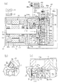
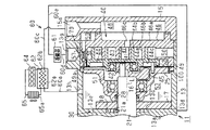
図1(a)に示すように、複合流体機械11のハウジング12は、筒状をなすセンタハウジング13と、このセンタハウジング13の一端(図1では左端)に接合されたフロントハウジング14と、センタハウジング13の他端(図1では右端)に接合されたリヤハウジング15と、から形成されている。センタハウジング13の内周面には、センタハウジング13内に向けて延びる仕切壁13aが形成されるとともに、この仕切壁13aによってハウジング12内が2つの空間に仕切られている。
(First embodiment)
Hereinafter, a first embodiment of the present invention will be described with reference to FIGS.
As shown in FIG. 1A, a
ハウジング12において、仕切壁13aとフロントハウジング14との間の空間には、回転電機としてのモータ・ジェネレータ20が収容されるとともに、仕切壁13aとリヤハウジング15との間の空間には、支持ブロック25及び膨張部40が収容されている。
In the
モータ・ジェネレータ20の駆動軸21は、フロントハウジング14、仕切壁13a、及び支持ブロック25に支持された軸受16によって回転可能に支持されている。駆動軸21には、モータロータ20aが駆動軸21と一体回転可能に固定されている。また、センタハウジング13の内周面には、ステータ20bがモータロータ20aを取り囲むように固定されている。
The
そして、モータ・ジェネレータ20は、ステータ20bのコイル20cへの通電によりモータロータ20aを回転させる電動機としての機能と、モータロータ20aが回転されることでステータ20bのコイル20cに電力を生じさせる発電機としての機能とを併せ持つ。なお、モータ・ジェネレータ20にはインバータ22を介してバッテリ23が接続されるとともに、モータ・ジェネレータ20で生じた電力はインバータ22を介してバッテリ23に蓄電されるようになっている。
The motor /
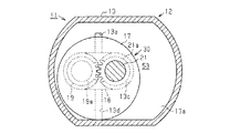
仕切壁13aのリヤハウジング15側(図1では右側)の面には、駆動軸21を取り囲むように長円状の凹部13cが形成されている。そして、仕切壁13aのリヤハウジング15側の面にサイドプレート17が固着されることにより、凹部13cが閉鎖されて仕切壁13aとサイドプレート17との間にポンプ室18が区画されている。また、図2に示すように、ポンプ室18には従動ギヤ19が収容されるとともに、仕切壁13aとサイドプレート17には、従動ギヤ19の軸部19aが回転可能に支持されている。また、ポンプ室18内には、駆動軸21に取着された主動ギヤ21aが収容されている。そして、ポンプ室18では、従動ギヤ19と主動ギヤ21aとが互いに噛み合わされた状態で配設されるとともに、ポンプ室18と、従動ギヤ19と、主動ギヤ21aとからギヤポンプ30が形成されている。
An
仕切壁13aにおけるポンプ室18より下側には、吸入通路13dが形成されている。この吸入通路13dは、一端がセンタハウジング13の外面(下面)に開口するとともに、他端がポンプ室18に連通するように形成されている。また、仕切壁13aにおけるポンプ室18より上側には、吐出通路13eが形成されている。この吐出通路13eは、一端がポンプ室18に連通するとともに、他端がサイドプレート17の周縁を越えて仕切壁13aの端面に開口している。
A
図1に示すように、仕切壁13aとリヤハウジング15との間の空間には、上述のように支持ブロック25が固設されるとともに、支持ブロック25とリヤハウジング15の間にスクロール式の膨張部40が設けられている。駆動軸21は支持ブロック25を貫通するとともに、支持ブロック25の内周面にはOリング製の軸シール28が装着されている。この軸シール28により、駆動軸21の周面と支持ブロック25の内周面との間がシールされている。
As shown in FIG. 1, the
支持ブロック25を貫通した駆動軸21の先端には、駆動軸21の中心軸Lに対して偏心した位置に偏心軸41が設けられるとともに、偏心軸41は駆動軸21の回転により中心軸Lの周りを公転するようになっている。偏心軸41にはブッシュ42が固定されるとともに、ブッシュ42は偏心軸41と共に中心軸Lの周りを公転するようになっている。このブッシュ42には軸受43を介して可動スクロール44が回転可能に支持されるとともに、カウンタウェイト45が固定されている。
An eccentric shaft 41 is provided at a position eccentric to the center axis L of the
可動スクロール44は、軸受43に支持された円盤状をなす可動側端板44aと、この可動側端板44aから突設された渦巻状の可動側渦巻壁44bとからなる。また、支持ブロック25のリヤハウジング15側には、固定スクロール46が可動スクロール44と対向するように固設されるとともに、支持ブロック25と固定スクロール46の対向する端面の間には、環状をなすプレート49が介装されている。
The
そして、支持ブロック25と固定スクロール46との間に可動スクロール44が配設されるとともに、可動スクロール44はプレート49の内側で旋回可能になっている。また、可動スクロール44の外周部において、プレート49に対向する端面には、Oリングよりなるシール部材52が装着されるとともに、このシール部材52によってプレート49と可動スクロール44との間がシールされている。
A
そして、可動スクロール44において、シール部材52より内周側と、支持ブロック25の内側によって囲まれる空間により背圧室51が区画されている。この背圧室51は、可動スクロール44に設けられたシール部材52と、支持ブロック25に設けられた軸シール28とによって気密にシールされている。そして、可動スクロール44において、固定スクロール46への対向面と反対側の面(支持ブロック25側の面)であり、背圧室51に露出する面が背面44cとなっている。
In the
固定スクロール46は、円盤状をなす固定側端板46aと、この固定側端板46aから可動スクロール44に向けて突設された渦巻状の固定側渦巻壁46bとを一体に備えている。そして、可動スクロール44の可動側渦巻壁44bと、固定スクロール46の固定側渦巻壁46bとは互いに噛み合わされ、可動スクロール44と固定スクロール46の間に容積変更可能な膨張室47が区画される。
The fixed
また、固定スクロール46における固定側端板46aの中央部には吸入口46cが形成されている。固定側端板46aとリヤハウジング15との間には、吸入室48が区画されるとともに、この吸入室48には吸入口46cを介して膨張前の膨張室47に連通している。また、リヤハウジング15には、吸入室48に連通する吸入ポート15aが形成されている。さらに、固定スクロール46の内周面と、可動スクロール44における可動側渦巻壁44bの最外周面との間、及び吸入室48の外周側には吐出室50が区画形成されるとともに、センタハウジング13には吐出室50に連通する吐出ポート13gが形成されている。
A
複合流体機械11において、センタハウジング13の内周面と、サイドプレート17と、支持ブロック25との間には、貯留部53が区画されている。この貯留部53は、駆動軸21を取り囲むように環状に形成されている。また、貯留部53は、仕切壁13aに形成された吐出通路13eを介して、ポンプ室18に連通している。このため、ギヤポンプ30のポンプ作用によって、ポンプ室18から吐出通路13eに吐出された高圧の作動流体は、吐出通路13eを介して貯留部53へ吐出されるようになっている。そして、貯留部53の圧力は、背圧室51の圧力よりも高い高圧領域となっている。また、センタハウジング13の上部には、貯留部53に連通する吐出孔13hが形成されている。そして、貯留部53へ吐出された作動流体は、吐出孔13hを介して後述するランキンサイクル装置60の熱交換器62へ導出されるようになっている。
In the
次に、上記複合流体機械11が組み込まれたランキンサイクル装置60について説明する。図1(a)に示すように、貯留部53に連通する吐出孔13hには第1流路60aを介して熱交換器62の吸熱器62aが接続されている。熱交換器62は、吸熱器62aに加え放熱器62bを備える。この放熱器62bは、排熱源としてのエンジン64に接続された冷却水循環経路65上に設けられている。冷却水循環経路65上にはラジエータ65aが設けられている。そして、冷却水循環経路65では、廃熱源としてのエンジン64からの流体として、冷却水が循環するようになっている。
Next, the
熱交換器62における吸熱器62aの吐出側には、第2流路60cを介して膨張部40における吸入ポート15aが接続されている。膨張部40の吐出ポート13gには、第3流路60dを介して凝縮器61が接続されている。凝縮器61の吐出側には第4流路60eを介してギヤポンプ30の吸入通路13dが接続されている。
The
そして、上記構成のランキンサイクル装置60においては、バッテリ23からの電力がインバータ22を介してモータ・ジェネレータ20に供給されるとモータ・ジェネレータ20が電動機として駆動され、ギヤポンプ30が駆動される。このギヤポンプ30から吐出された作動流体は、吐出通路13e、貯留部53、及び吐出孔13hを経由して、第1流路60aから熱交換器62に導出される。よって、本実施形態では、吐出通路13e、貯留部53、及び、吐出孔13hにより、ギヤポンプ30からの作動流体を熱交換器62に導出する主流路が形成されている。
In the
そして、熱交換器62において、吸熱器62aと放熱器62bとの間での熱交換により、作動流体がエンジン64からの排熱によって加熱されるとともに、熱エネルギーを受け取る。加熱後の高温高圧の作動流体は、第2流路60cを介して吸入ポート15aから膨張部40の膨張室47に導入されて膨張し、この膨張により膨張部40が機械的エネルギー(駆動力)を出力する。そして、この駆動力によって可動スクロール44が旋回し、モータ・ジェネレータ20の駆動軸21が回転されるとともにギヤポンプ30が駆動される。
Then, in the
このとき、エンジン64からの排熱量が大きく、膨張部40からの出力により、駆動軸21が予め設定された所定回転数を越えて回転する場合には、モータ・ジェネレータ20を発電機として機能させて駆動軸21の回転数を抑えるようにする。そして、所定回転数を越える出力は電力に変換され、インバータ22を介してバッテリ23に充電される。
At this time, if the amount of exhaust heat from the
膨張を終えて圧力が低下した高温の作動流体は、吐出室50に吐出された後、吐出ポート13gを介して第3流路60dへ吐出される。第3流路60dへ吐出された作動流体は、凝縮器61を通過して液化し、第4流路60eを介して吸入通路13dからポンプ室18に導入される。そして、膨張部40からの出力により駆動されるギヤポンプ30により、ポンプ室18に導入された作動流体は、吐出通路13eを経由して貯留部53へ吐出される。
The hot working fluid whose pressure has been reduced after finishing the expansion is discharged into the
貯留部53が作動流体により満たされると、オーバーフローした作動流体が吐出孔13hから第1流路60aに吐出され、第1流路60aを介して熱交換器62へ供給される。以後、上述したように、作動流体は、膨張部40、凝縮器61、及びギヤポンプ30を流れて、エンジン64が駆動されている間は、作動流体はランキンサイクル装置60の回路を循環する。
When the
次に、可動スクロール44を固定スクロール46に押し付けるため、ギヤポンプ30から吐出された作動流体を背圧室51に導入するための導入手段について説明する。
図1(a)及び(b)に示すように、支持ブロック25には、導入手段としての導入路54が形成されるとともに、この導入路54によって、ギヤポンプ30の吐出側から熱交換器62の入口側までの高圧領域(貯留部53)の作動流体を背圧室51に導入できるようになっている。導入路54は、ギヤポンプ30から熱交換器62に作動流体を導出する主流路(吐出通路13e、貯留部53、吐出孔13h)から分岐した流路である。
Next, introduction means for introducing the working fluid discharged from the
As shown in FIGS. 1A and 1B, the
導入路54において、貯留部53側の開口端にはフィルタ55が固設されるとともに、このフィルタ55によって貯留部53から背圧室51に導入される作動流体中の異物が除去されるようになっている。また、導入路54において、フィルタ55より背圧室51側には、絞りプレート56が固定されるとともに、この絞りプレート56には、導入路54の流路径を小さくする(絞る)絞り孔56aが形成されている。
In the
図1(c)に示すように、固定スクロール46において、可動スクロール44の外周側に区画された吐出室50よりも外側には、導出路57が形成されている。この導出路57は、一端がプレート49に形成された連通孔49aを介して背圧室51に連通するとともに、他端が吸入室48の外周側に区画された吐出室50に連通している。なお、吐出室50は、膨張室47で膨張した低圧の作動流体が吐出される領域であり、背圧室51より低圧の低圧領域となっている。
As shown in FIG. 1C, in the fixed
導出路57には、導出路57をプレート49側から吐出室50に向けて拡径させることで形成された段差によって弁座57aが形成されている。また、導出路57内には、バネ受け58が固定されるとともに、このバネ受け58には圧縮状態のコイルバネ59の一端が支持されている。また、バネ受け58には逃がし通路58aが形成されるとともに、この逃がし通路58aによって、バネ受け58よりもコイルバネ59側の空間と、バネ受け58よりも吐出室50側の空間とを連通させている。コイルバネ59の他端にはボールバルブ59aが固定されるとともに、コイルバネ59の伸縮によりボールバルブ59aは弁座57aに対し接離可能になっている。
A
コイルバネ59のバネ力は、背圧室51の圧力が予め設定された適正値を越えると収縮するように設定されている。そして、コイルバネ59の伸縮に伴うボールバルブ59aの弁座57aに対する接離により、背圧室51と吐出室50との差圧が予め設定された適正値に調整されるようになっている。すなわち、背圧室51の圧力が予め設定された値を越え、吐出室50との差圧が予め設定された適正値より高くなると、ボールバルブ59aが弁座57aから離間して、背圧室51の圧力を低下させ、差圧を低下させる。このとき、背圧室51から導出路57に導出された作動流体は、逃がし通路58aを介して吐出室50に排出される。
The spring force of the coil spring 59 is set so as to contract when the pressure in the
一方、背圧室51の圧力が予め設定された適正値を下回り、吐出室50との差圧が予め設定された適正値より低くなると、ボールバルブ59aが弁座57aに着座して、背圧室51の圧力を上昇させ、差圧を上昇させる。したがって、本実施形態では、弁座57aと、コイルバネ59と、ボールバルブ59aと、バネ受け58とから導出側差圧調整機構70が構成されている。
On the other hand, when the pressure in the
次に、上記複合流体機械11が組み込まれたランキンサイクル装置60の作用について説明する。ランキンサイクル装置60において、貯留部53には高圧の作動流体が貯留されている。そして、この貯留部53と背圧室51とは、導入路54を介して連通されるとともに、導入路54内の絞り孔56aにより、貯留部53の作動流体が背圧室51に噴霧される。すなわち、背圧室51には、熱交換器62に導出される前の作動流体、詳細には熱交換器62から熱エネルギーを受け取る前の作動流体が導入される。
Next, the operation of the
そして、背圧室51に高圧の作動流体が導入されることにより、可動スクロール44の可動側端板44aの背面44cには背圧力が作用し、可動スクロール44が、軸方向に沿って固定スクロール46に押し付けられる。このため、可動スクロール44の可動側端板44aと、固定スクロール46の固定側渦巻壁46bの先端、及び可動スクロール44の可動側渦巻壁44bの先端と、固定スクロール46の固定側端板46aが、互いに押し付けられ、膨張室47の密閉性が高められる。その結果、膨張室47からの作動流体の漏れが抑制され、膨張室47で効率良く膨張させることができる。
Then, when a high-pressure working fluid is introduced into the
なお、背圧室51への作動流体の導入により、背圧室51の背圧力が変動するが、導出側差圧調整機構70によって、背圧室51と吐出室50の差圧が適正値に調整される。このため、背圧室51の背圧力が適正値に調整され、可動スクロール44の固定スクロール46への押し付け力を安定させることができる。
Although the back pressure of the
上記実施形態によれば、以下のような効果を得ることができる。
(1)膨張部40における可動スクロール44の背面44c側に背圧室51を形成するとともに、この背圧室51に、ギヤポンプ30の吐出側から熱交換器62の入口側までの高圧領域の作動流体を導入するようにした。この作動流体の導入により背圧室51の背圧力を高め、可動スクロール44を固定スクロール46に押し付けるようにして、膨張室47の密閉性を高めるようにした。すなわち、背圧力を発生させるため、背圧室51に導入される作動流体は、熱交換器62で熱エネルギーを受け取る前の作動流体である。よって、熱交換器62で作動流体が受け取った熱エネルギーは、背圧力を発生させるために用いられず、全て膨張部40での機械的エネルギーの変換に用いられる。その結果として、背圧力によって膨張室47の密閉性を高める構成としても、機械的エネルギーの出力効率が低下することがない。
According to the above embodiment, the following effects can be obtained.
(1) A
(2)ギヤポンプ30と膨張部40をハウジング12内に収容した複合流体機械11をランキンサイクル装置60に組み込むとともに、複合流体機械11のハウジング12内に導入路54を設け、この導入路54を経由して高圧の作動流体を背圧室51に導入するようにした。このため、例えば、ギヤポンプ30と膨張部40とを別体に分け、ギヤポンプ30から吐出された作動流体をハウジング12外で配管を介して背圧室51に導入するようにする場合と比べると、配管が必要無いことから、ランキンサイクル装置60の設置スペースをコンパクトにすることができる。
(2) The
(3)ギヤポンプ30と膨張部40をハウジング12内に収容した複合流体機械11をランキンサイクル装置60に組み込むとともに、複合流体機械11の軸方向に沿ってギヤポンプ30に隣り合わせて膨張部40を並設した。このため、例えば、複合流体機械11の軸方向に沿って、ギヤポンプ30、モータ・ジェネレータ20、及び膨張部40が並設されている場合と比べると、ギヤポンプ30と膨張部40との間にモータ・ジェネレータ20が介在しない分だけ、ギヤポンプ30と膨張部40の間の距離を短くすることができる。その結果、導入路54の通路長さも短くすることができ、ギヤポンプ30から吐出された作動流体を背圧室51に速やかに導入することができる。
(3) The
(4)背圧室51と、この背圧室51より低圧の吐出室50とを導出路57で連通させるとともに、導出路57内に導出側差圧調整機構70として弁座57a、コイルバネ59、ボールバルブ59a、及びバネ受け58を設けた。そして、ボールバルブ59aの弁座57aに対する接離により、背圧室51と吐出室50との差圧を適正値に調整するようにしたため、可動スクロール44の固定スクロール46に向けた押し付け力を安定させることができる。
(4) The
(5)導入路54内に絞りプレート56を設け、この絞りプレート56に小径の絞り孔56aを形成することで、ギヤポンプ30の吐出側から熱交換器62の入口側までの高圧領域の作動流体を背圧室51に導入するようにした。そして、導入路54にフィルタ55を設けた。このため、フィルタ55によって作動流体に含まれる異物を除去することができ、絞り孔56aが異物で詰まることを防止することができる。
(5) By providing a
(6)ハウジング12内に、ギヤポンプ30から吐出された作動流体の貯留部53を設けるとともに、ハウジング12に貯留部53から熱交換器62へ作動流体を導出するための吐出孔13hを形成した。そして、ギヤポンプ30から熱交換器62へ作動流体を導出するための主流路を貯留部53内とした。また、この貯留部53に面する支持ブロック25に、貯留部53(主流路)から分岐する導入路54を形成し、この導入路54によって高圧の作動流体を背圧室51に導入するようにした。そして、この導入路54内にフィルタ55を設けた。その結果、作動流体は貯留部53(主流路)を流れて熱交換器62に導出されるため、作動流体中に含まれる異物のほとんどは主流路での流れに乗って熱交換器62に向けて流れる。よって、導入路54には異物がほとんど流れ込まないため、フィルタ55の表面積を小さくすることができる、すなわち、フィルタ55をコンパクトにすることができる。
(6) A
(7)背圧室51に高圧の作動流体を導入し、背圧力によって可動スクロール44を固定スクロール46に押し付けるようにした。背圧力は、差圧調整機構70により適正値に調整することができるため、可動スクロール44の押し付け力を安定させることができる。このため、可動スクロール44の固定スクロール46への押し付けを、付勢バネ等の機械的構成を用いて行う場合と異なり、押し付け力不足による作動流体の漏れ損失や過剰な押し付け力による機械的損失を低減することができる。
(7) A high-pressure working fluid is introduced into the
(第2の実施形態)
次に、本発明を具体化した第2の実施形態を図3にしたがって説明する。また、第1の実施形態の複合流体機械11と同一構成については同一符号を付すなどし、その重複する説明を省略又は簡略する。なお、第2の実施形態では、第1の実施形態で導入手段を構成した導入路54は形成されていない。
(Second Embodiment)
Next, a second embodiment of the present invention will be described with reference to FIG. In addition, the same components as those of the
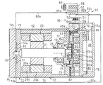
図3に示すように、複合流体機械71のハウジング72は、筒状をなすセンタハウジング73と、センタハウジング73の一端(図3では左端)に接合されたサイドプレート74と、サイドプレート74に接合されたフロントハウジング75と、センタハウジング73の他端(図1では右端)に接合されたリヤハウジング76とから形成されている。また、センタハウジング73内には支持ブロック25が固設されるとともに、支持ブロック25とリヤハウジング76との間には膨張部40が収容されている。さらに、センタハウジング73内にはモータ・ジェネレータ20が収容されている。
As shown in FIG. 3, the
サイドプレート74のフロントハウジング75側の面には、駆動軸21を取り囲むように円形状の凹部74aが形成されている。そして、サイドプレート74にフロントハウジング75が接合されることにより、凹部74aが閉鎖されてポンプ室77が区画されている。ポンプ室77には従動ギヤ(図示せず)及び駆動軸21に取着された主動ギヤ80が収容されている。そして、ポンプ室77では、従動ギヤと主動ギヤ80とが互いに噛み合わされた状態で配設されるとともに、ポンプ室77と、従動ギヤと、主動ギヤ80とからギヤポンプ90が形成されている。本実施形態の複合流体機械71は、軸方向に沿ってギヤポンプ90、モータ・ジェネレータ20、及び膨張部40が並設されている。
A
サイドプレート74におけるポンプ室77より下側には、吸入通路74bが形成されている。この吸入通路74bは、一端(図3では下端)がサイドプレート74の外面に開口するとともに、他端がポンプ室77に連通するように形成されている。また、サイドプレート74におけるポンプ室77より上側には、吐出通路74cが形成されている。この吐出通路74cは、一端がポンプ室77に連通するとともに、他端がサイドプレート74の外面に開口している。そして、吸入通路74bには、凝縮器61に接続された第4流路60eが接続されるとともに、吐出通路74cには第1流路60aを介して熱交換器62の吸熱器62aが接続されている。
A
さらに、サイドプレート74及びセンタハウジング73には、第1連通路82が形成されている。この第1連通路82は、ギヤポンプ90の吐出側から熱交換器62の入口側までの領域の一部である吐出通路74cに連通している。また、支持ブロック25には、第1連通路82と背圧室51とを連通させる第2連通路83が形成されている。そして、ギヤポンプ90の吐出口付近の高圧の作動流体は、第1連通路82及び第2連通路83を介して背圧室51に導入されるようになっている。よって、本実施形態では、第1連通路82と第2連通路83とが、ギヤポンプ90の吐出側から熱交換器62の入口側までの高圧領域から背圧室51に作動流体を導入する導入手段を形成している。なお、図示しないが、第1連通路82又は第2連通路83内にはフィルタが設けられている。
Further, a
したがって、上記第2の実施形態によれば、第1の実施形態の(1)、(2)、(4)、(6)及び(7)と同様の効果に加え、以下のような効果を得ることができる。
(8)ギヤポンプ90と膨張部40を一体化した複合流体機械71をランキンサイクル装置60に組み込むとともに、複合流体機械11の軸方向に沿ってギヤポンプ90、モータ・ジェネレータ20、及び膨張部40を並設した。そして、ハウジング72の厚み内に第1連通路82を形成するとともに、支持ブロック25に第2連通路83を形成し、ギヤポンプ90と背圧室51とを連通させた。このため、ギヤポンプ90と膨張部40との間にモータ・ジェネレータ20が介在していても、ギヤポンプ90から吐出された作動流体を背圧室51に導入することができる。
Therefore, according to the second embodiment, in addition to the same effects as (1), (2), (4), (6) and (7) of the first embodiment, the following effects are obtained. Obtainable.
(8) The
(第3の実施形態)
次に、本発明を具体化した第3の実施形態を図4にしたがって説明する。また、第1の実施形態の複合流体機械11と同一構成については同一符号を付すなどし、その重複する説明を省略又は簡略する。なお、第3の実施形態では、第1の実施形態で導入手段を形成した導入路54は形成されていない。
(Third embodiment)
Next, a third embodiment of the present invention will be described with reference to FIG. In addition, the same components as those of the
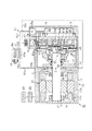
図4に示すように、複合流体機械91において、支持ブロック25の内周面には、第1の実施形態のOリング製の軸シール28と異なり、Vパッキン製の軸シール93が装着されるとともに、この軸シール93により駆動軸21の周面と支持ブロック25の内周面との間がシールされている。また、サイドプレート17と、支持ブロック25の先端との間には、駆動軸21を取り囲むようにOリング製のシール部材94が介装されるとともに、このシール部材94により支持ブロック25とサイドプレート17との間がシールされている。なお、第3の実施形態では、吐出通路13eは、貯留部53に連通せず、センタハウジング13の外面に開口している。
As shown in FIG. 4, in the
そして、ギヤポンプ30の吐出側(吐出通路13e側)において、駆動軸21の付近は、吸入通路13d側の低圧と、吐出通路13e側の高圧との間の圧力であり、やや高圧よりの中間圧となっている。この中間圧は、背圧室51の圧力より高くなっているため、駆動軸21付近の作動流体は、ギヤポンプ30から背圧室51に向けて流れようとする。ここで、軸シール93の駆動軸21に対する密接力を緩めに設定しておき、駆動軸21に沿ったギヤポンプ30から背圧室51への作動流体の漏れを許容させる。すると、ギヤポンプ30の駆動軸21付近の作動流体は、駆動軸21に沿って背圧室51に向けて流れ、この作動流体により背圧室51の背圧力を高めることができる。したがって、本実施形態では、駆動軸21及び軸シール93が、ギヤポンプ30の吐出側から熱交換器62の入口側までの高圧領域の作動流体を背圧室51に導入するための導入手段を構成している。
On the discharge side (
したがって、上記第3の実施形態によれば、第1の実施形態の(1)、(2)、(6)及び(7)と同様の効果に加え、以下のような効果を得ることができる。
(9)ギヤポンプ30の駆動軸21付近の作動流体を、駆動軸21に沿って背圧室51に導入するようにした。このため、ギヤポンプ30から吐出された高圧の作動流体を背圧室51に導入するため、ハウジング12や支持ブロック25に導入路を形成する場合と比べると、より簡単な構成とすることができる。
Therefore, according to the third embodiment, in addition to the same effects as (1), (2), (6) and (7) of the first embodiment, the following effects can be obtained. .
(9) The working fluid in the vicinity of the
(第4の実施形態)
次に、本発明を具体化した第4の実施形態を図5及び図6にしたがって説明する。また、第1の実施形態の複合流体機械11と同一構成については同一符号を付すなどし、その重複する説明を省略又は簡略する。なお、第4の実施形態では、第1の実施形態で導入手段を形成した導入路54は形成されていない。
(Fourth embodiment)
Next, a fourth embodiment embodying the present invention will be described with reference to FIGS. In addition, the same components as those of the
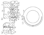
図5及び図6(a)に示すように、支持ブロック25には、供給路100が厚み方向に貫通して形成されるとともに、この供給路100は一端が貯留部53に向けて開口するとともに、他端がプレート49に向けて開口している。また、図6(a)及び図6(c)に示すように、プレート49には、気化通路49bがプレート49の周方向に沿って半周に亘って延びるとともに、プレート49を厚み方向を貫通して形成されている。そして、プレート49は、支持ブロック25と固定スクロール46の対向する端面の間に挟持されていることから、それら端面によって気化通路49bはシールされている。
As shown in FIG. 5 and FIG. 6A, a
気化通路49bの一端は、供給路100の他端に連通するとともに、気化通路49bの他端は、背圧室51に連通している。貯留部53と、背圧室51とは、供給路100及び気化通路49bを介して連通するとともに、本実施形態では、供給路100及び気化通路49bによって、導入手段としての導入通路が構成されている。
One end of the
さて、貯留部53の高圧の作動流体(液体)は、貯留部53と背圧室51との圧力差に基づいて、供給路100によって絞られつつ、気化通路49bに供給される。ここで、気化通路49bを区画する固定スクロール46は、膨張部40で膨張した後の高温の作動流体によって加熱されている。このため、気化通路49bを流れる液状の作動流体は、気化通路49bを通過する際に固定スクロール46との熱交換により、加熱され、気化する。よって、本実施形態では、固定スクロール46が、膨張部40の吐出側の作動流体と液状の作動流体とを熱交換させる熱交換部として機能する。そして、背圧室51には、気化した作動流体が導入される。
Now, the high-pressure working fluid (liquid) in the
したがって、第4の実施形態によれば、第1の実施形態の(1)〜(4)、(6)及び(7)と同様の効果に加え、以下のような効果を得ることができる。
(10)貯留部53の液状の作動流体を、支持ブロック25に形成した供給路100及びプレート49に形成した気化通路49bを介して背圧室51に導入するようにした。プレート49は、高温の固定スクロール46に熱的に結合されているため、気化通路49bを作動流体が流れる際、固定スクロール46の熱により作動流体を気化させることができる。したがって、背圧室51には、気体の作動流体が導入されるため、背圧室51内でカウンタウェイト45及び偏心軸41が回転しても、背圧室51の作動流体が液体の場合と比べると、作動流体による抵抗を小さくすることができ、モータ・ジェネレータ20の動力損失を低減することができる。
Therefore, according to the fourth embodiment, in addition to the same effects as (1) to (4), (6) and (7) of the first embodiment, the following effects can be obtained.
(10) The liquid working fluid in the
(11)気化通路49bは、プレート49に形成されるとともに、プレート49の周方向へ半周に亘って延びるように形成されている。そして、この気化通路49bを通過する作動流体そのものにより、プレート49を可動スクロール44に向けて押し付けて可動スクロール44を固定スクロール46に押し付けることができる。したがって、背圧室51からの背圧力に加え、プレート49を介した押し付け力により、可動スクロール44を固定スクロール46により強く押し付けることができる。
(11) The
(12)貯留部53の液状の作動流体を気化させるため、プレート49に気化通路49bを形成した。すなわち、プレート49を用いて可動スクロール44を背圧力によって固定スクロール46に押し付けるようにした。そして、プレート49の材質を選定することで、可動スクロール44の端面に対する摺動性を向上させることができる。また、プレート49は、金属板状の部材であるため、例えば、気化通路49bを支持ブロック25や固定スクロール46に形成する場合と比べると、気化通路49bを簡単に形成することができる。
(12) In order to vaporize the liquid working fluid in the
(13)貯留部53の液状の作動流体は、固定スクロール46と熱交換して気化する。固定スクロール46は、エンジン64からの熱を受け取った高温の作動流体によって加熱されている。よって、膨張部40の一部である固定スクロール46を用いて作動流体を気化することができ、新たに部品を追加することなく作動流体を気化することができる。
(13) The liquid working fluid in the
(第5の実施形態)
次に、本発明を具体化した第5の実施形態を図7にしたがって説明する。また、第1の実施形態の複合流体機械11と同一構成については同一符号を付すなどし、その重複する説明を省略又は簡略する。なお、第5の実施形態では、第1の実施形態で導入手段を形成した導入路54は形成されていない。
(Fifth embodiment)
Next, a fifth embodiment of the present invention will be described with reference to FIG. In addition, the same components as those of the
図7(a)及び図7(b)に示すように、支持ブロック25は、プレート49に対向する側に第1圧入部25aが円板状に形成されるとともに、その第1圧入部25aよりもギヤポンプ30側に、第1圧入部25aよりも小径の第2圧入部25bが形成されている。第1圧入部25aにおいて、プレート49と反対側(ギヤポンプ30側)の端面には、膨張部40からの作動流体が供給される供給空間25cが環状に凹設されるとともに、導入空間25cの開口端には支持面25dが形成されている。なお、図7(c)に示すように、センタハウジング13には、供給空間25cと吐出室50とを連通させる供給通路102が形成されている。そして、供給空間25cには、供給通路102を介して膨張後の高温の作動流体が供給されている。
As shown in FIGS. 7A and 7B, the
図7(b)及び図7(c)に示すように、センタハウジング13においては、第1圧入部25aの外周側に第1壁部131が形成されるとともに、この第1壁部131の内側に膨張部40が設けられている。また、センタハウジング13において、第1壁部131よりもギヤポンプ30側に、第1壁部131よりも小径の第2壁部132が形成されている。センタハウジング13の内周面には、第1壁部131と第2壁部132との内径差により、第1段差部133が環状に形成されている。さらに、センタハウジング13において、第2壁部132よりもギヤポンプ30側に、第2壁部132より小径の第3壁部134が形成されている。センタハウジング13の内周面には、第2壁部132と第3壁部134との内径差により、第2段差部135が環状に形成されている。
As shown in FIGS. 7B and 7C, in the
そして、支持ブロック25は、第1圧入部25aが第1壁部131の内側に圧入されるとともに、第2圧入部25bが第3壁部134の内側に圧入されている。支持ブロック25における支持面25dと、センタハウジング13における段差部133との間には、熱交換部のうちの熱交換部材としての熱交換プレート101の外周部が挟持されている。この熱交換プレート101の外周側には、熱交換フィン101aが蛇腹状に形成されている。
In the
また、支持ブロック25における第2圧入部25bの外周面と、センタハウジング13における第2壁部132の内周面と、第2段差部135と、熱交換プレート101とで区画される空間には、導入空間103が環状に区画されている。この導入空間103は、支持ブロック25の供給空間25cと対向する位置に形成されている。
Further, in the space defined by the outer peripheral surface of the second press-
図7(c)に示すように、センタハウジング13には、貯留部53と導入空間103とを連通させる第1導入流路104が形成されている。また、図7(b)に示すように、支持ブロック25には、導入空間103と背圧室51とを連通させる第2導入通路108が形成されている。そして、貯留部53と背圧室51とは、第1導入流路104と、導入空間103と、第2導入通路108とを介して連通している。よって、本実施形態では、第1導入流路104と、導入空間103と、第2導入通路108とから導入手段としての導入通路が構成されている。
As shown in FIG. 7C, the
第1導入流路104には、背圧室51と吐出室50との差圧を調整する導入側差圧調整機構110が設けられている。導入側差圧調整機構110は、外部制御弁として構成されており、第1導入流路104に制御弁を配置するとともに、この制御弁を、コントローラに信号接続する。また、背圧室51及び吐出室50(低圧領域)それぞれの圧力を圧力センサ等により検出可能にする。そして、圧力センサによって検出された背圧室51及び吐出室50の圧力に基づき、コントローラが制御弁の開度を調整し、差圧を調整する。
The first
そして、背圧室51と吐出室50との差圧が予め設定された適正値に調整されるようになっている。すなわち、背圧室51の圧力が予め設定された値を越え、吐出室50との差圧が予め設定された適正値より高いことを適宜の検出手段で検出すると、導入側差圧調整機構110により第1導入流路104が絞られる。その結果、背圧室51に導入される作動流体が減少し、背圧室51の圧力を低下させ、差圧を低下させる。
The differential pressure between the
一方、背圧室51の圧力が予め設定された適正値を下回り、吐出室50との差圧が予め設定された適正値より低くなると、導入側差圧調整機構110による第1導入流路104の絞り量が減少する。その結果、背圧室51に導入される作動流体が増加し、背圧室51がの圧力を上昇させ、差圧を上昇させる。
On the other hand, when the pressure in the
さて、貯留部53の高圧の作動流体(液体)は、第1導入流路104の導入側差圧調整機構110によって絞られつつ、導入空間103に導入される。また、熱交換プレート101を挟んで導入空間103に対向する供給空間25cには、膨張部40で膨張した高温の作動流体が供給されている。
Now, the high-pressure working fluid (liquid) in the
よって、熱交換プレート101は、供給空間25cに供給された作動流体によって加熱されている。このため、導入空間103に導入された作動流体は、熱交換プレート101との熱交換により、加熱され、気化する。よって、本実施形態では、熱交換プレート101が熱交換部のうちの熱交換部材として機能する。そして、背圧室51には、気化した作動流体が導入される。
Therefore, the
なお、背圧室51への作動流体の導入により、背圧室51の背圧力が変動するが、導入側差圧調整機構110によって、背圧室51と吐出室50の差圧が適正値に調整される。このため、背圧室51の背圧力が適正値に調整され、可動スクロール44の固定スクロール46への押し付け力を安定させることができる。
Although the back pressure of the
したがって、第5の実施形態によれば、第1の実施形態の(1)〜(4)、(6)及び(7)と同様の効果に加え、以下のような効果を得ることができる。
(14)貯留部53の液状の作動流体を、センタハウジング13に形成した第1導入流路104、導入空間103、及び第2導入通路108を介して背圧室51に導入するようにした。導入空間103は、熱交換プレート101を挟んで供給空間25cに対向しており、この供給空間25cには、膨張部40で膨張した後の高温の作動流体が供給される。このため、熱交換プレート101は、高温の作動流体によって加熱されているため、導入空間103に作動流体が導入されると、その作動流体を気化させることができる。したがって、背圧室51には、気体の作動流体が導入されるため、背圧室51内でカウンタウェイト45及び偏心軸41が回転しても、背圧室51の作動流体が液体の場合と比べると、作動流体による抵抗を小さくすることができ、モータ・ジェネレータ20の動力損失を低減することができる。
Therefore, according to the fifth embodiment, in addition to the same effects as (1) to (4), (6) and (7) of the first embodiment, the following effects can be obtained.
(14) The liquid working fluid in the
(15)作動流体を気化させるため、膨張後の作動流体と熱交換プレート101を介して熱交換させた。そして、熱交換プレート101には、熱交換率を高めるため、熱交換フィン101aを形成した。熱交換プレート101のように膨張部40とは別部材を用いることで、作動流体同士の熱交換面積を適宜設定することができ、作動流体を効率良く気化させることができる。
(15) In order to vaporize the working fluid, heat was exchanged with the expanded working fluid via the
なお、上記実施形態は以下のように変更してもよい。
○ 第4の実施形態において、気化通路49bをプレート49に形成したが、支持ブロック25又は固定スクロール46に形成してもよい。
In addition, you may change the said embodiment as follows.
In the fourth embodiment, the
○ 第4の実施形態において、気化通路49bの通路幅は任意に変更してもよい。例えば、気化通路49bにおいて、供給路100と対向する一端を小径の孔とし、その孔より他端側を幅広に形成し、気化通路49bに絞りを形成してもよい。
In the fourth embodiment, the passage width of the
○ 図3の2点鎖線に示すように、第1流路60aにおいて、熱交換器62の入口付近から分岐された分岐流路95を第2連通路83に連通させてもよい。そして、ギヤポンプ90から吐出され、かつ熱交換器62に導入される前の高圧の作動流体を、第1流路60a、分岐流路95、及び第2連通路83を経由して背圧室51に導入してもよい。この場合、分岐流路95、及び第2連通路83により導入手段が形成される。なお、分岐流路95又は第2連通路83に導入側差圧調整機構を設けて背圧室51と吐出室50との差圧を適正値に調整するようにしてもよい。
As shown by a two-dot chain line in FIG. 3, in the
○ 第1及び第2の実施形態では、導出路57に導出側差圧調整機構70を設けて背圧室51と吐出室50との差圧を適正値に調整するようにしたが、これに限らない。導出側差圧調整機構70の代わりに、第1の実施形態では導入路54に導入側差圧調整機構を設け、第2の実施形態では第1連通路82又は第2連通路83に導入側差圧調整機構を設けて差圧を調整してもよい。
In the first and second embodiments, the derivation-side differential
○ 第3の実施形態では、駆動軸21及び軸シール93が導入手段を構成したが、この第3の実施形態において、軸シール93を圧力差によって駆動軸21に対する密接力(シール力)を変更可能に構成し導入側差圧調整機構としてもよい。この場合、導出側差圧調整機構70は削除する。\'81@○ 第4の実施形態では、導出路57に導出側差圧調整機構70を設けて背圧室51と吐出室50との差圧を適正値に調整するようにしたが、導出側差圧調整機構70の代わりに、供給路100に導入側差圧調整機構を設けて背圧室51と吐出室50との差圧を調整してもよい。
○ In the third embodiment, the
○ 第5の実施形態では、第1導入流路104に導入側差圧調整機構110を設けて背圧室51と吐出室50との差圧を適正値に調整するようにしたが、導入側差圧調整機構110の代わりに、第1の実施形態のように導出路57に導出側差圧調整機構70を設けて差圧を調整してもよい。
In the fifth embodiment, the introduction side differential
○ 各実施形態では、モータ・ジェネレータ20、ギヤポンプ30,90、及び膨張部40が一体化された複合流体機械11,71,91をランキンサイクル装置60に組み込んで回路を構成したが、モータ・ジェネレータ、ギヤポンプ、及び膨張部をそれぞれ単体として回路に組み込んでもよい。そして、ギヤポンプと膨張部の背圧室とを導入手段としての配管で接続し、ギヤポンプから吐出された高圧の作動流体を配管を介して背圧室に導入するようにしてもよい。
In each embodiment, the complex
○ 各実施形態では、複合流体機械11,71,91のハウジング内にモータ・ジェネレータ20、ギヤポンプ30,90、膨張部40、及び導入手段が収容されていたが、複合流体機械のハウジング内には、ギヤポンプ30,90、膨張部40、及び導入手段が収容され、ギヤポンプ30,90はハウジング外に設けられていてもよい。これによれば、ギヤポンプ30,90がハウジング内に設けられている場合と比べると、複合流体機械を短くすることができる。
In each embodiment, the motor /
○ 各実施形態において、ポンプはギヤポンプ30,90の他の形態のポンプとしてもよい。
○ 各実施形態では、複合流体機械11,71,91をランキンサイクル装置60のみに用いたが、複合流体機械11,71,91に圧縮部及びクラッチ機構を一体に設けて、冷凍サイクルを並設してもよい。
In each embodiment, the pump may be a pump of another form of the gear pumps 30 and 90.
In each embodiment, the composite
○ 排熱源からの流体は、エンジン64からの排気ガスであってもよい。
○ 駆動軸21をハウジング12の外に突出させ、その駆動軸21の突出端が動力伝達手段(クラッチ、プーリ、ベルト等)を介してエンジン64に連結されていてもよい。
The fluid from the exhaust heat source may be exhaust gas from the
The
○ モータ・ジェネレータ20をオルタネータに変更してもよい。
次に、上記実施形態及び別例から把握できる技術的思想について以下に追記する。
(イ)前記導出手段にはフィルタが設けられている請求項1〜請求項9のうちいずれか一項に記載のランキンサイクル装置。
○ The motor /
Next, the technical idea that can be grasped from the above embodiment and other examples will be described below.
(B) The Rankine cycle device according to any one of claims 1 to 9, wherein the derivation means is provided with a filter.
(ロ)作動流体を吐出するポンプ、前記ポンプから吐出された作動流体と排熱源からの流体との間で熱交換させる熱交換器、前記熱交換器で熱交換された作動流体を膨張させて機械的エネルギーを出力する膨張部、を有する回路を備えるランキンサイクル装置に用いられ、前記膨張部、及び前記ポンプをハウジング内に一体に備える複合流体機械であって、前記膨張部は、固定スクロール、及び前記固定スクロールに対して駆動軸の回転によって旋回する可動スクロールを備え、前記可動スクロールにおける前記固定スクロールへの対向面と反対側の背面側に背圧室を備え、さらに、前記駆動軸の軸方向に沿って前記可動スクロールを前記固定スクロールに押し付ける背圧力を発生させるために、前記ポンプの吐出側から前記熱交換器の入口側までの高圧領域から前記背圧室に前記作動流体を導入するための導入手段を備えることを特徴とする複合流体機械。 (B) a pump that discharges the working fluid, a heat exchanger that exchanges heat between the working fluid discharged from the pump and the fluid from the exhaust heat source, and the working fluid that has exchanged heat with the heat exchanger is expanded. A composite fluid machine that is used in a Rankine cycle device including a circuit having an expansion unit that outputs mechanical energy, and that includes the expansion unit and the pump integrally in a housing, the expansion unit including a fixed scroll, And a movable scroll that rotates by rotation of a drive shaft with respect to the fixed scroll, a back pressure chamber is provided on the back side of the movable scroll opposite to the surface facing the fixed scroll, and the shaft of the drive shaft In order to generate a back pressure that presses the movable scroll against the fixed scroll along the direction, the inlet of the heat exchanger from the discharge side of the pump Composite fluid machine, characterized in that from the high pressure region to comprise the introduction means for introducing the working fluid into the back pressure chamber.
(ハ)前記導入手段は、前記高圧領域と前記背圧室を連通させる導入通路であり、該導入通路に、液状の前記作動流体を気化させる熱交換部を備える技術的思想(ロ)に記載の複合流体機械。 (C) The introduction means is an introduction passage that communicates the high pressure region and the back pressure chamber, and the introduction passage includes a heat exchange section that vaporizes the liquid working fluid. Complex fluid machinery.
(ニ)前記熱交換部は、前記膨張部において、前記熱交換器で熱交換された作動流体からの熱が伝達される部位である技術的思想(ハ)に記載の複合流体機械。
(ホ)前記熱交換部は、前記膨張部の吐出側の作動流体と前記液状の作動流体とを熱交換させる熱交換部材である技術的思想(ハ)に記載の複合流体機械。
(D) The composite fluid machine according to the technical idea (c), in which the heat exchanging part is a part to which heat from the working fluid heat-exchanged by the heat exchanger is transmitted in the expansion part.
(E) The composite fluid machine according to the technical concept (c), wherein the heat exchange unit is a heat exchange member that exchanges heat between the working fluid on the discharge side of the expansion unit and the liquid working fluid.
(ヘ)前記導入手段には、前記背圧室と、該背圧室より低圧領域との差圧を適正値に調整する導入側差圧調整機構が設けられている技術的思想(ハ)〜(ホ)のうちいずれか一項に記載の複合流体機械。 (F) The technical idea (c) in which the introduction means is provided with an introduction-side differential pressure adjustment mechanism that adjusts a differential pressure between the back pressure chamber and a lower pressure region than the back pressure chamber to an appropriate value. The composite fluid machine according to any one of (e).
(ト)前記背圧室には、該背圧室より低圧領域と前記背圧室を連通させる導出路が接続され、該導出路には前記背圧室と前記低圧領域との差圧を適正値に調整する導出側差圧調整機構が設けられている技術的思想(ロ)〜(ヘ)のうちいずれか一項に記載の複合流体機械。 (G) A lead-out path that connects the back pressure chamber and the back pressure chamber to the back pressure chamber is connected to the back pressure chamber, and an appropriate differential pressure between the back pressure chamber and the low pressure area is connected to the lead path. The composite fluid machine according to any one of the technical ideas (b) to (f), wherein a derivation side differential pressure adjusting mechanism for adjusting the value is provided.
(チ)前記膨張部及び前記導入手段は、複合流体機械のハウジング内に設けられている技術的思想(ロ)〜(ト)のうちいずれか一項に記載の複合流体機械。
(リ)前記膨張部及び前記ポンプは、複合流体機械のハウジング内に設けられるとともに、前記導入手段は前記ハウジング内に設けられている技術的思想(ロ)〜(ト)のうちいずれか一項に記載の複合流体機械。
(H) The complex fluid machine according to any one of the technical ideas (B) to (G) provided in the housing of the complex fluid machine, wherein the expansion portion and the introduction unit are provided.
(I) The expansion portion and the pump are provided in a housing of a complex fluid machine, and the introduction means is any one of technical ideas (b) to (g) provided in the housing. A composite fluid machine according to claim 1.
(ヌ)前記ハウジング内では、前記軸方向に沿って前記ポンプと前記膨張部が隣り合うように並設されている技術的思想(リ)に記載の複合流体機械。 (Nu) In the housing, the composite fluid machine according to the technical idea (I), in which the pump and the expansion portion are arranged side by side along the axial direction.
11,71,91…複合流体機械、12,72…ハウジング、21…駆動軸(導入手段)、30,90…ポンプとしてのギヤポンプ、40…膨張部、44…可動スクロール、44c…背面、46…熱交換部としての固定スクロール、49b…導入手段としての導入通路を構成する気化通路、51…背圧室、53…高圧領域としての貯留部、54…導入手段としての導入路、57…導出路、60…ランキンサイクル装置、62…熱交換器、64…排熱源としてのエンジン、70…導出側差圧調整機構、82…導入手段を形成する第1連通路、83…導入手段を形成する第2連通路、93…導入手段を形成する軸シール、100…導入手段としての導入通路を構成する供給路、103…導入手段としての導入通路を形成する導入空間、104…導入手段としての導入通路を形成する第1導入流路、108…導入手段としての導入通路を形成する第2導入通路、110…導入側差圧調整機構。
DESCRIPTION OF
Claims (9)
前記ポンプから吐出された作動流体と排熱源からの流体との間で熱交換させる熱交換器と、
前記熱交換器で熱交換された作動流体を膨張させて機械的エネルギーを出力する膨張部と、を有する回路を備えるランキンサイクル装置であって、
前記膨張部は、固定スクロール、及び前記固定スクロールに対して駆動軸の回転によって旋回する可動スクロールを備え、前記可動スクロールにおける前記固定スクロールへの対向面と反対側の背面側に背圧室を備え、
さらに、前記駆動軸の軸方向に沿って前記可動スクロールを前記固定スクロールに押し付ける背圧力を発生させるために、高圧領域から前記背圧室に前記作動流体を導入するための導入手段を備えており、
前記高圧領域は、前記ポンプの吐出側から前記熱交換器の入口側までの領域であることを特徴とするランキンサイクル装置。 A pump for discharging the working fluid;
A heat exchanger for exchanging heat between the working fluid discharged from the pump and the fluid from the exhaust heat source;
A Rankine cycle device comprising a circuit having an expansion part that expands the working fluid heat-exchanged by the heat exchanger and outputs mechanical energy,
The inflatable portion includes a fixed scroll and a movable scroll that revolves by rotation of a drive shaft with respect to the fixed scroll, and includes a back pressure chamber on the back side of the movable scroll opposite to the surface facing the fixed scroll. ,
Furthermore, in order to generate a back pressure that presses the movable scroll against the fixed scroll along the axial direction of the drive shaft, there is provided an introducing means for introducing the working fluid from the high pressure region into the back pressure chamber. ,
The Rankine cycle device according to claim 1, wherein the high-pressure region is a region from a discharge side of the pump to an inlet side of the heat exchanger.
Priority Applications (5)
| Application Number | Priority Date | Filing Date | Title |
|---|---|---|---|
| JP2011186221A JP2012207655A (en) | 2011-03-15 | 2011-08-29 | Rankine cycle apparatus |
| EP12157227A EP2500570A2 (en) | 2011-03-15 | 2012-02-28 | Scroll compressor for a Rankine cycle |
| US13/417,761 US20120234007A1 (en) | 2011-03-15 | 2012-03-12 | Rankine cycle apparatus |
| CN2012100657974A CN102678208A (en) | 2011-03-15 | 2012-03-13 | Rankine cycle apparatus |
| KR1020120025308A KR20120105365A (en) | 2011-03-15 | 2012-03-13 | Rankine cycle apparatus and complex fluid machine incorporated therein |
Applications Claiming Priority (3)
| Application Number | Priority Date | Filing Date | Title |
|---|---|---|---|
| JP2011056845 | 2011-03-15 | ||
| JP2011056845 | 2011-03-15 | ||
| JP2011186221A JP2012207655A (en) | 2011-03-15 | 2011-08-29 | Rankine cycle apparatus |
Publications (1)
| Publication Number | Publication Date |
|---|---|
| JP2012207655A true JP2012207655A (en) | 2012-10-25 |
Family
ID=45814361
Family Applications (1)
| Application Number | Title | Priority Date | Filing Date |
|---|---|---|---|
| JP2011186221A Withdrawn JP2012207655A (en) | 2011-03-15 | 2011-08-29 | Rankine cycle apparatus |
Country Status (5)
| Country | Link |
|---|---|
| US (1) | US20120234007A1 (en) |
| EP (1) | EP2500570A2 (en) |
| JP (1) | JP2012207655A (en) |
| KR (1) | KR20120105365A (en) |
| CN (1) | CN102678208A (en) |
Cited By (1)
| Publication number | Priority date | Publication date | Assignee | Title |
|---|---|---|---|---|
| WO2017043471A1 (en) * | 2015-09-09 | 2017-03-16 | サンデンホールディングス株式会社 | Scroll fluid machine and refrigerating device in which same is used |
Families Citing this family (16)
| Publication number | Priority date | Publication date | Assignee | Title |
|---|---|---|---|---|
| KR101151206B1 (en) * | 2008-08-05 | 2012-05-29 | 주식회사 두원전자 | A scroll compressor improved in function of back pressure control |
| CN103089314A (en) * | 2013-01-21 | 2013-05-08 | 石亮 | High-efficiency reliable vortex expansion power generator |
| US20140219844A1 (en) * | 2013-02-06 | 2014-08-07 | Daimler Ag | Expansion device for use in a working medium circuit and method for operating an expansion device |
| CN103867299B (en) * | 2013-02-16 | 2016-03-16 | 摩尔动力(北京)技术股份有限公司 | Split transcapsidation Rankine-cycle engine |
| CN104100298A (en) * | 2013-04-03 | 2014-10-15 | 汉钟精机股份有限公司 | A scroll expansion generator |
| JP2015108327A (en) * | 2013-12-04 | 2015-06-11 | 株式会社神戸製鋼所 | Refrigerant pump and binary power generation system using the refrigerant pump |
| DE102013020762A1 (en) * | 2013-12-07 | 2015-06-11 | Daimler Ag | Scroll machine |
| CN103967527A (en) * | 2014-05-09 | 2014-08-06 | 广州东凌机械工业有限公司 | Scroll expansion power generating device |
| KR20160028710A (en) | 2014-09-04 | 2016-03-14 | 한온시스템 주식회사 | Scroll expander |
| JP6395929B2 (en) * | 2015-05-22 | 2018-09-26 | 三菱電機株式会社 | Scroll compressor |
| KR101892803B1 (en) * | 2016-04-26 | 2018-08-29 | 학교법인 두원학원 | An apparatus for back pressure control in scroll compressor |
| CN106014978A (en) * | 2016-07-05 | 2016-10-12 | 湖南贝特新能源科技有限公司 | Scroll compressor |
| KR102549777B1 (en) * | 2016-12-21 | 2023-06-30 | 삼성전자주식회사 | Scroll compressor |
| KR102553485B1 (en) * | 2018-12-06 | 2023-07-10 | 삼성전자주식회사 | High-pressure type scroll compressor |
| KR102515120B1 (en) | 2019-01-21 | 2023-03-29 | 한온시스템 주식회사 | Scroll compressor |
| WO2020151298A1 (en) * | 2019-01-25 | 2020-07-30 | 艾默生环境优化技术(苏州)有限公司 | Expander |
Family Cites Families (15)
| Publication number | Priority date | Publication date | Assignee | Title |
|---|---|---|---|---|
| US457762A (en) * | 1891-08-11 | Signors of one-third to albert l | ||
| US1080063A (en) * | 1913-05-05 | 1913-12-02 | Ebenezer Hill | Air-compressor. |
| JP3575201B2 (en) | 1996-12-25 | 2004-10-13 | ダイキン工業株式会社 | Scroll type fluid machine |
| EP1443201B1 (en) * | 2003-01-28 | 2016-03-23 | Denso Corporation | Fluid machine operable in both pump mode and motor mode and waste heat recovering system having the same |
| DE102004018860A1 (en) * | 2003-04-22 | 2004-11-25 | Denso Corp., Kariya | fluid machine |
| JP4039320B2 (en) * | 2003-06-17 | 2008-01-30 | 株式会社デンソー | Fluid machinery |
| DE102005024685A1 (en) * | 2004-05-31 | 2005-12-29 | Denso Corp., Kariya | heat circuit |
| JP4549941B2 (en) * | 2004-10-05 | 2010-09-22 | 株式会社デンソー | Complex fluid machinery |
| DE102006009211B4 (en) * | 2005-03-02 | 2015-06-11 | Denso Corporation | Fluid pump and fluid machine |
| JP2006242133A (en) * | 2005-03-04 | 2006-09-14 | Denso Corp | Fluid machinery |
| JP2006300004A (en) * | 2005-04-22 | 2006-11-02 | Denso Corp | Expander |
| JP4864689B2 (en) * | 2006-04-17 | 2012-02-01 | 株式会社デンソー | Fluid machinery and Rankine cycle |
| CH697852B1 (en) * | 2007-10-17 | 2009-02-27 | Eneftech Innovation Sa | compression spiral device or expansion. |
| JP2010249130A (en) * | 2009-03-27 | 2010-11-04 | Sanden Corp | Fluid machine |
| JP5106464B2 (en) * | 2009-03-30 | 2012-12-26 | サンデン株式会社 | Fluid machine, refrigerant circuit and waste heat utilization apparatus using fluid machine |
-
2011
- 2011-08-29 JP JP2011186221A patent/JP2012207655A/en not_active Withdrawn
-
2012
- 2012-02-28 EP EP12157227A patent/EP2500570A2/en not_active Withdrawn
- 2012-03-12 US US13/417,761 patent/US20120234007A1/en not_active Abandoned
- 2012-03-13 CN CN2012100657974A patent/CN102678208A/en active Pending
- 2012-03-13 KR KR1020120025308A patent/KR20120105365A/en not_active Abandoned
Cited By (1)
| Publication number | Priority date | Publication date | Assignee | Title |
|---|---|---|---|---|
| WO2017043471A1 (en) * | 2015-09-09 | 2017-03-16 | サンデンホールディングス株式会社 | Scroll fluid machine and refrigerating device in which same is used |
Also Published As
| Publication number | Publication date |
|---|---|
| KR20120105365A (en) | 2012-09-25 |
| CN102678208A (en) | 2012-09-19 |
| EP2500570A2 (en) | 2012-09-19 |
| US20120234007A1 (en) | 2012-09-20 |
Similar Documents
| Publication | Publication Date | Title |
|---|---|---|
| JP2012207655A (en) | Rankine cycle apparatus | |
| KR101576459B1 (en) | Scroll compressor and refrigeration equipment using it | |
| JP6302813B2 (en) | Scroll compressor and refrigeration cycle apparatus using the same | |
| US20040255591A1 (en) | Fluid machine for converting heat into mechanical rotational force | |
| US8419395B2 (en) | Compressor and refrigeration apparatus | |
| JP6241605B2 (en) | Scroll type fluid machinery | |
| JP2015113817A (en) | Scroll type compressor | |
| JP2004137979A (en) | Expansion machine | |
| CN102395759A (en) | Fluid machine and refrigeration cycle apparatus | |
| WO2013140458A1 (en) | Scroll compressor | |
| JP2017172504A (en) | Scroll compressor | |
| JP6061044B2 (en) | Scroll compressor | |
| JP7619981B2 (en) | Scroll compressor and heat pump water heater | |
| JP6416559B2 (en) | Scroll compressor and air conditioner | |
| JP2013164064A (en) | Complex fluid machine | |
| JP2008157152A (en) | Rankine cycle | |
| JP2018112108A (en) | Rotary compressor | |
| JP2010038120A (en) | Fluid machine | |
| JP5797586B2 (en) | Scroll type fluid machinery | |
| JP7122112B2 (en) | Scroll fluid machine and Rankine cycle | |
| JP2011047567A (en) | Refrigerating device | |
| WO2014103413A1 (en) | Composite fluid machine | |
| JP2020041443A (en) | Scroll expander | |
| KR20160028710A (en) | Scroll expander | |
| JP2015031210A (en) | Rankine cycle device |
Legal Events
| Date | Code | Title | Description |
|---|---|---|---|
| A300 | Application deemed to be withdrawn because no request for examination was validly filed |
Free format text: JAPANESE INTERMEDIATE CODE: A300 Effective date: 20141104 |