JP2012207667A - プラズマ式ブレード先端間隙制御装置 - Google Patents
プラズマ式ブレード先端間隙制御装置 Download PDFInfo
- Publication number
- JP2012207667A JP2012207667A JP2012160065A JP2012160065A JP2012207667A JP 2012207667 A JP2012207667 A JP 2012207667A JP 2012160065 A JP2012160065 A JP 2012160065A JP 2012160065 A JP2012160065 A JP 2012160065A JP 2012207667 A JP2012207667 A JP 2012207667A
- Authority
- JP
- Japan
- Prior art keywords
- annular
- blade tip
- shroud
- plasma
- plasma generator
- Prior art date
- Legal status (The legal status is an assumption and is not a legal conclusion. Google has not performed a legal analysis and makes no representation as to the accuracy of the status listed.)
- Granted
Links
Images
Classifications
-
- F—MECHANICAL ENGINEERING; LIGHTING; HEATING; WEAPONS; BLASTING
- F01—MACHINES OR ENGINES IN GENERAL; ENGINE PLANTS IN GENERAL; STEAM ENGINES
- F01D—NON-POSITIVE DISPLACEMENT MACHINES OR ENGINES, e.g. STEAM TURBINES
- F01D11/00—Preventing or minimising internal leakage of working-fluid, e.g. between stages
- F01D11/08—Preventing or minimising internal leakage of working-fluid, e.g. between stages for sealing space between rotor blade tips and stator
- F01D11/14—Adjusting or regulating tip-clearance, i.e. distance between rotor-blade tips and stator casing
- F01D11/20—Actively adjusting tip-clearance
-
- F—MECHANICAL ENGINEERING; LIGHTING; HEATING; WEAPONS; BLASTING
- F05—INDEXING SCHEMES RELATING TO ENGINES OR PUMPS IN VARIOUS SUBCLASSES OF CLASSES F01-F04
- F05D—INDEXING SCHEME FOR ASPECTS RELATING TO NON-POSITIVE-DISPLACEMENT MACHINES OR ENGINES, GAS-TURBINES OR JET-PROPULSION PLANTS
- F05D2270/00—Control
- F05D2270/01—Purpose of the control system
- F05D2270/17—Purpose of the control system to control boundary layer
- F05D2270/172—Purpose of the control system to control boundary layer by a plasma generator, e.g. control of ignition
-
- Y—GENERAL TAGGING OF NEW TECHNOLOGICAL DEVELOPMENTS; GENERAL TAGGING OF CROSS-SECTIONAL TECHNOLOGIES SPANNING OVER SEVERAL SECTIONS OF THE IPC; TECHNICAL SUBJECTS COVERED BY FORMER USPC CROSS-REFERENCE ART COLLECTIONS [XRACs] AND DIGESTS
- Y02—TECHNOLOGIES OR APPLICATIONS FOR MITIGATION OR ADAPTATION AGAINST CLIMATE CHANGE
- Y02T—CLIMATE CHANGE MITIGATION TECHNOLOGIES RELATED TO TRANSPORTATION
- Y02T50/00—Aeronautics or air transport
- Y02T50/60—Efficient propulsion technologies, e.g. for aircraft
-
- Y—GENERAL TAGGING OF NEW TECHNOLOGICAL DEVELOPMENTS; GENERAL TAGGING OF CROSS-SECTIONAL TECHNOLOGIES SPANNING OVER SEVERAL SECTIONS OF THE IPC; TECHNICAL SUBJECTS COVERED BY FORMER USPC CROSS-REFERENCE ART COLLECTIONS [XRACs] AND DIGESTS
- Y10—TECHNICAL SUBJECTS COVERED BY FORMER USPC
- Y10S—TECHNICAL SUBJECTS COVERED BY FORMER USPC CROSS-REFERENCE ART COLLECTIONS [XRACs] AND DIGESTS
- Y10S415/00—Rotary kinetic fluid motors or pumps
- Y10S415/914—Device to control boundary layer
Landscapes
- Engineering & Computer Science (AREA)
- Mechanical Engineering (AREA)
- General Engineering & Computer Science (AREA)
- Turbine Rotor Nozzle Sealing (AREA)
- Structures Of Non-Positive Displacement Pumps (AREA)
Abstract
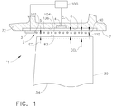
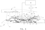
【解決手段】ブレード先端間隙制御システム(11)は、回転ブレード先端(82)を囲む環状シュラウド(72)と、ブレード先端(82)から半径方向外側にかつ離れて配置された環状プラズマ発生器(2)とを含む。環状プラズマ発生器(2)は、環状シュラウド(72)の半径方向内向き表面(7)の環状グルーブ(6)内に配置され誘電体材料(5)によって分離された半径方向内側及び外側電極(3、4)を含む。プラズマ発生器(2)は、環状シュラウド(72)とブレード先端(82)との間に環状プラズマを生成し、また環状プラズマによって環状シュラウド(72)とブレード先端(82)との間に生成されかつ該環状シュラウド(72)とブレード先端(82)との間の間隙(CL)よりも小さい有効間隙(ECL)を生成するように、作動可能である。
【選択図】 図1
Description
例えば離陸、減速などのような過渡条件の間に発生するおそれがあるシールとブレード先端との間の干渉又は摩耗を減少させるか又は排除しながら、エンジンがその運転サイクルの大部分において最小のシール間隙で作動するのを可能にするように設計される。また、ブレード先端とシュラウドとの間の摩擦を回避するか又は減少させることによってブレード先端間隙を維持する受動間隙制御システムも存在する。
3 内側電極
4 外側電極
5 誘電体材料
6 環状グルーブ
7 内向き表面
8 エンジン中心線
9 ブレード先端間隙システム
10 ガスタービンエンジン
11 プラズマ式ブレード先端間隙制御システム
12 能動間隙制御システム
13 ファンセクション
14 ファン
15 ファンバイパスダクト
16 ブースタ又は低圧圧縮機(LPC)
17 出口案内ベーン
18 高圧圧縮機(HPC)
19 空気供給入口
20 燃焼セクション
22 高圧タービン(HPT)
24 低圧タービン(LPT)
26 高圧シャフト
28 低圧シャフト
30 HPTロータ
32 加圧ファン空気供給部
34 タービンブレード
36 熱制御空気
40 タービンブレード先端能動間隙制御装置
42 空気供給管
44 空気弁
48 電子式コントローラ
50 分配マニホルド
54 ヘッダ管
56 プレナム
60 スプレー管
64 ステータ組立体
66 外側ケーシング
68 前方ケースフック
70 後方ケースフック
72 シュラウド
73 シュラウドセグメント
74 前方シュラウドフック
76 後方シュラウドフック
80 シュラウド支持体
82 ブレード先端
84 前方熱制御リング
86 後方熱制御リング
90 プラズマ
100 AC電源
102 端縁部
104 領域
106 グルーブセグメント
110 境界層
CL 運転間隙
CCL 冷間間隙
ECL 有効間隙
Claims (10)
- ガスタービンエンジンのプラズマ式ブレード先端間隙制御システム(11)であって、
回転ブレード先端(82)を囲む環状シュラウド(72)と、
環状プラズマ発生器(2)と
を含み、
前記環状プラズマ発生器(2)の全体が、前記ブレード先端(82)から半径方向外側にかつ離れて間隔を置いて配置されている
ことを特徴とする、システム(11)。 - 前記環状プラズマ発生器(2)が、誘電体材料(5)によって分離された半径方向内側及び外側電極(3、4)をさらに含む、請求項1記載のシステム(11)。
- 前記環状プラズマ発生器(2)が、前記環状シュラウド(72)に取付けられる、請求項1記載のシステム(11)。
- 前記電極に接続されて該電極に高電圧AC電位を供給するAC電源(100)をさらに含む、請求項3記載のシステム(11)。
- 前記誘電体材料(5)が、前記環状シュラウド(72)の半径方向内向き表面(7)の環状グルーブ(6)内に配置される、請求項4記載のシステム(11)。
- 前記プラズマ発生器(2)が、前記環状シュラウド(72)とブレード先端(82)との間に環状プラズマ(90)を形成し、また前記環状プラズマ(90)によって前記環状シュラウド(72)とブレード先端(82)との間に生成されかつ該環状シュラウド(72)とブレード先端(82)との間の冷間間隙(CCL)よりも小さい有効間隙(ECL)を形成する、ように作動可能である、
請求項1記載のシステム(11)。 - 前記環状シュラウド(72)が、セグメント化されかつシュラウドセグメント(73)を有し、
環状グルーブセグメント(106)が、前記環状シュラウドセグメント(73)の半径方向内向き表面(7)内に設けられ、
前記環状プラズマ発生器(2)が、前記環状グルーブセグメント(107)内の誘電体材料(5)によって分離された半径方向内側及び外側電極(3、4)を含む、
請求項1記載のシステム(11)。 - 航空機ガスタービンエンジン(10)のブレード先端間隙システム(9)であって、
回転ブレード先端(82)を囲む環状シュラウド(72)と、
熱制御空気(36)を使用して前記回転ブレード先端(82)と環状シュラウド(72)との間の先端運転間隙(CL)を維持するようになった能動間隙制御システム(12)と、
環状プラズマ発生器(2)と
を含み、
前記環状プラズマ発生器(2)の全体が、前記ブレード先端(82)から半径方向外側にかつ離れて間隔を置いて配置されている
ことを特徴とする、システム(9)。 - 前記環状プラズマ発生器(2)が、前記環状グルーブセグメント(107)内の誘電体材料(5)によって分離された半径方向内側及び外側電極(3、4)を含む、
請求項8記載のシステム(9)。 - 前記環状シュラウド(72)が、セグメント化されかつシュラウドセグメント(73)を有し、
環状グルーブセグメント(106)が、前記環状シュラウドセグメント(73)の半径方向内向き表面(7)内に設けられている
請求項8記載のシステム(9)。
Applications Claiming Priority (2)
| Application Number | Priority Date | Filing Date | Title |
|---|---|---|---|
| US11/580,789 | 2006-10-13 | ||
| US11/580,789 US7819626B2 (en) | 2006-10-13 | 2006-10-13 | Plasma blade tip clearance control |
Related Parent Applications (1)
| Application Number | Title | Priority Date | Filing Date |
|---|---|---|---|
| JP2007265053A Division JP5048444B2 (ja) | 2006-10-13 | 2007-10-11 | プラズマ式ブレード先端間隙制御装置 |
Publications (2)
| Publication Number | Publication Date |
|---|---|
| JP2012207667A true JP2012207667A (ja) | 2012-10-25 |
| JP5312647B2 JP5312647B2 (ja) | 2013-10-09 |
Family
ID=38893313
Family Applications (2)
| Application Number | Title | Priority Date | Filing Date |
|---|---|---|---|
| JP2007265053A Expired - Fee Related JP5048444B2 (ja) | 2006-10-13 | 2007-10-11 | プラズマ式ブレード先端間隙制御装置 |
| JP2012160065A Expired - Fee Related JP5312647B2 (ja) | 2006-10-13 | 2012-07-19 | プラズマ式ブレード先端間隙制御装置 |
Family Applications Before (1)
| Application Number | Title | Priority Date | Filing Date |
|---|---|---|---|
| JP2007265053A Expired - Fee Related JP5048444B2 (ja) | 2006-10-13 | 2007-10-11 | プラズマ式ブレード先端間隙制御装置 |
Country Status (4)
| Country | Link |
|---|---|
| US (1) | US7819626B2 (ja) |
| EP (1) | EP1914391A3 (ja) |
| JP (2) | JP5048444B2 (ja) |
| CA (1) | CA2605521C (ja) |
Cited By (2)
| Publication number | Priority date | Publication date | Assignee | Title |
|---|---|---|---|---|
| US11078794B2 (en) | 2016-02-16 | 2021-08-03 | Ihi Corporation | Airfoil structure manufacturing method |
| US11639667B2 (en) | 2017-12-26 | 2023-05-02 | Subaru Corporation | Rotor support device, rotor, gas turbine engine, and aircraft |
Families Citing this family (45)
| Publication number | Priority date | Publication date | Assignee | Title |
|---|---|---|---|---|
| US9347331B2 (en) * | 2007-06-11 | 2016-05-24 | University Of Florida Research Foundation, Inc. | Electrodynamic control of blade clearance leakage loss in turbomachinery applications |
| US20090065064A1 (en) * | 2007-08-02 | 2009-03-12 | The University Of Notre Dame Du Lac | Compressor tip gap flow control using plasma actuators |
| US8317457B2 (en) * | 2007-12-28 | 2012-11-27 | General Electric Company | Method of operating a compressor |
| US8282337B2 (en) | 2007-12-28 | 2012-10-09 | General Electric Company | Instability mitigation system using stator plasma actuators |
| US8282336B2 (en) | 2007-12-28 | 2012-10-09 | General Electric Company | Instability mitigation system |
| US8348592B2 (en) | 2007-12-28 | 2013-01-08 | General Electric Company | Instability mitigation system using rotor plasma actuators |
| US20090169363A1 (en) * | 2007-12-28 | 2009-07-02 | Aspi Rustom Wadia | Plasma Enhanced Stator |
| US20100284785A1 (en) * | 2007-12-28 | 2010-11-11 | Aspi Rustom Wadia | Fan Stall Detection System |
| US20100047055A1 (en) * | 2007-12-28 | 2010-02-25 | Aspi Rustom Wadia | Plasma Enhanced Rotor |
| US20100047060A1 (en) * | 2007-12-28 | 2010-02-25 | Aspi Rustom Wadia | Plasma Enhanced Compressor |
| US20090169356A1 (en) * | 2007-12-28 | 2009-07-02 | Aspi Rustom Wadia | Plasma Enhanced Compression System |
| US20100284795A1 (en) * | 2007-12-28 | 2010-11-11 | General Electric Company | Plasma Clearance Controlled Compressor |
| US20100205928A1 (en) * | 2007-12-28 | 2010-08-19 | Moeckel Curtis W | Rotor stall sensor system |
| US20100290906A1 (en) * | 2007-12-28 | 2010-11-18 | Moeckel Curtis W | Plasma sensor stall control system and turbomachinery diagnostics |
| US8006497B2 (en) * | 2008-05-30 | 2011-08-30 | Honeywell International Inc. | Diffusers, diffusion systems, and methods for controlling airflow through diffusion systems |
| US7916311B2 (en) * | 2008-10-31 | 2011-03-29 | General Electric Company | Method and system for inspecting blade tip clearance |
| US8451459B2 (en) | 2008-10-31 | 2013-05-28 | General Electric Company | Method and system for inspecting blade tip clearance |
| US7984614B2 (en) * | 2008-11-17 | 2011-07-26 | Honeywell International Inc. | Plasma flow controlled diffuser system |
| US20100172747A1 (en) * | 2009-01-08 | 2010-07-08 | General Electric Company | Plasma enhanced compressor duct |
| US20100170224A1 (en) * | 2009-01-08 | 2010-07-08 | General Electric Company | Plasma enhanced booster and method of operation |
| US8435001B2 (en) * | 2009-12-17 | 2013-05-07 | Siemens Energy, Inc. | Plasma induced flow control of boundary layer at airfoil endwall |
| US8585356B2 (en) * | 2010-03-23 | 2013-11-19 | Siemens Energy, Inc. | Control of blade tip-to-shroud leakage in a turbine engine by directed plasma flow |
| US8500404B2 (en) | 2010-04-30 | 2013-08-06 | Siemens Energy, Inc. | Plasma actuator controlled film cooling |
| US9458855B2 (en) * | 2010-12-30 | 2016-10-04 | Rolls-Royce North American Technologies Inc. | Compressor tip clearance control and gas turbine engine |
| US9284886B2 (en) * | 2011-12-30 | 2016-03-15 | Clearsign Combustion Corporation | Gas turbine with Coulombic thermal protection |
| US20130251500A1 (en) * | 2012-03-23 | 2013-09-26 | Kin-Leung Cheung | Gas turbine engine case with heating layer and method |
| EP2884823B3 (en) * | 2012-08-08 | 2019-03-06 | National Institute of Advanced Industrial Science and Technology | Surface plasma actuator |
| GB201300597D0 (en) * | 2012-10-22 | 2013-02-27 | Rolls Royce Plc | Clearance control |
| US20140119879A1 (en) * | 2012-10-29 | 2014-05-01 | General Electric Company | Turbomachine plasma seal system |
| US8920124B2 (en) | 2013-02-14 | 2014-12-30 | Siemens Energy, Inc. | Turbine blade with contoured chamfered squealer tip |
| EP3097270B1 (en) * | 2014-01-24 | 2020-07-29 | United Technologies Corporation | Gas turbine engine inner case with non-integral vanes |
| US10371050B2 (en) | 2014-12-23 | 2019-08-06 | Rolls-Royce Corporation | Gas turbine engine with rotor blade tip clearance flow control |
| US10087772B2 (en) | 2015-12-21 | 2018-10-02 | General Electric Company | Method and apparatus for active clearance control for high pressure compressors using fan/booster exhaust air |
| US10329941B2 (en) * | 2016-05-06 | 2019-06-25 | United Technologies Corporation | Impingement manifold |
| US10612409B2 (en) | 2016-08-18 | 2020-04-07 | United Technologies Corporation | Active clearance control collector to manifold insert |
| WO2018085152A1 (en) | 2016-11-04 | 2018-05-11 | Clearsign Combustion Corporation | Plasma pilot |
| US10487679B2 (en) * | 2017-07-17 | 2019-11-26 | United Technologies Corporation | Method and apparatus for sealing components of a gas turbine engine with a dielectric barrier discharge plasma actuator |
| FR3073007B1 (fr) | 2017-10-27 | 2019-09-27 | Safran Aircraft Engines | Dispositif de maintien d'un tube de refroidissement pour carter de turbomachine |
| EP3730800B1 (en) | 2017-12-21 | 2023-12-06 | Ihi Corporation | Axial compressor |
| CN109779948B (zh) * | 2019-01-17 | 2021-01-05 | 沈阳航空航天大学 | 一种用于提高轴流风机性能的等离子式叶顶间隙密封方法 |
| US11342831B2 (en) | 2019-10-07 | 2022-05-24 | Lockheed Martin Corporation | Homopolar turbine |
| CN112129213B (zh) * | 2020-10-26 | 2021-07-27 | 南京航空航天大学 | 基于脉冲介质阻挡放电的叶尖间隙测量系统及测量方法 |
| CN116085067A (zh) | 2021-11-05 | 2023-05-09 | 通用电气公司 | 具有流体导管系统的燃气涡轮发动机及其操作方法 |
| US11788425B2 (en) * | 2021-11-05 | 2023-10-17 | General Electric Company | Gas turbine engine with clearance control system |
| JP7786722B2 (ja) * | 2022-01-28 | 2025-12-16 | 国立研究開発法人産業技術総合研究所 | プラズマアクチュエータおよび流体機械 |
Citations (4)
| Publication number | Priority date | Publication date | Assignee | Title |
|---|---|---|---|---|
| JPH0249903A (ja) * | 1988-06-29 | 1990-02-20 | United Technol Corp <Utc> | ガスタービンエンジンのステータ構造 |
| JPH05340270A (ja) * | 1992-02-07 | 1993-12-21 | General Electric Co <Ge> | 締まりばめをなす方法及び締まりばめハンガ |
| JP2005201277A (ja) * | 2004-01-16 | 2005-07-28 | Snecma Moteurs | 改良されたガスタービン間隙制御装置 |
| WO2005114013A1 (en) * | 2004-05-20 | 2005-12-01 | Rolls-Royce Plc | Sealing arrangement |
Family Cites Families (5)
| Publication number | Priority date | Publication date | Assignee | Title |
|---|---|---|---|---|
| US5100291A (en) * | 1990-03-28 | 1992-03-31 | General Electric Company | Impingement manifold |
| US7334394B2 (en) * | 2003-09-02 | 2008-02-26 | The Ohio State University | Localized arc filament plasma actuators for noise mitigation and mixing enhancement |
| US7597537B2 (en) * | 2005-12-16 | 2009-10-06 | General Electric Company | Thermal control of gas turbine engine rings for active clearance control |
| US7503179B2 (en) * | 2005-12-16 | 2009-03-17 | General Electric Company | System and method to exhaust spent cooling air of gas turbine engine active clearance control |
| US7605595B2 (en) | 2006-09-29 | 2009-10-20 | General Electric Company | System for clearance measurement and method of operating the same |
-
2006
- 2006-10-13 US US11/580,789 patent/US7819626B2/en not_active Expired - Fee Related
-
2007
- 2007-10-04 CA CA 2605521 patent/CA2605521C/en not_active Expired - Fee Related
- 2007-10-11 JP JP2007265053A patent/JP5048444B2/ja not_active Expired - Fee Related
- 2007-10-12 EP EP07254056A patent/EP1914391A3/en not_active Withdrawn
-
2012
- 2012-07-19 JP JP2012160065A patent/JP5312647B2/ja not_active Expired - Fee Related
Patent Citations (4)
| Publication number | Priority date | Publication date | Assignee | Title |
|---|---|---|---|---|
| JPH0249903A (ja) * | 1988-06-29 | 1990-02-20 | United Technol Corp <Utc> | ガスタービンエンジンのステータ構造 |
| JPH05340270A (ja) * | 1992-02-07 | 1993-12-21 | General Electric Co <Ge> | 締まりばめをなす方法及び締まりばめハンガ |
| JP2005201277A (ja) * | 2004-01-16 | 2005-07-28 | Snecma Moteurs | 改良されたガスタービン間隙制御装置 |
| WO2005114013A1 (en) * | 2004-05-20 | 2005-12-01 | Rolls-Royce Plc | Sealing arrangement |
Cited By (2)
| Publication number | Priority date | Publication date | Assignee | Title |
|---|---|---|---|---|
| US11078794B2 (en) | 2016-02-16 | 2021-08-03 | Ihi Corporation | Airfoil structure manufacturing method |
| US11639667B2 (en) | 2017-12-26 | 2023-05-02 | Subaru Corporation | Rotor support device, rotor, gas turbine engine, and aircraft |
Also Published As
| Publication number | Publication date |
|---|---|
| EP1914391A2 (en) | 2008-04-23 |
| US7819626B2 (en) | 2010-10-26 |
| JP5048444B2 (ja) | 2012-10-17 |
| JP5312647B2 (ja) | 2013-10-09 |
| EP1914391A3 (en) | 2009-04-15 |
| JP2008095692A (ja) | 2008-04-24 |
| US20080089775A1 (en) | 2008-04-17 |
| CA2605521A1 (en) | 2008-04-13 |
| CA2605521C (en) | 2015-04-21 |
Similar Documents
| Publication | Publication Date | Title |
|---|---|---|
| JP5312647B2 (ja) | プラズマ式ブレード先端間隙制御装置 | |
| JP5196974B2 (ja) | 上流プラズマ遮蔽式フィルム冷却 | |
| JP5185601B2 (ja) | 下流プラズマ遮蔽式フィルム冷却 | |
| EP1798381B1 (en) | Thermal control of gas turbine engine rings for active clearance control | |
| US7503179B2 (en) | System and method to exhaust spent cooling air of gas turbine engine active clearance control | |
| EP1923539B1 (en) | Gas turbine with active tip clearance control | |
| EP1630385B1 (en) | Method and apparatus for maintaining rotor assembly tip clearances | |
| JPH04301102A (ja) | ガスタービンエンジンの間隙制御装置 | |
| JP2013189977A (ja) | ガスタービンロータ動翼とケーシングのその場でのクリアランス制御 | |
| CN1811135A (zh) | 保护转子组件顶部间隙的方法和装置 | |
| EP2009250B1 (en) | Annular turbine casing of a gas turbine engine and corresponding turbine assembly | |
| US11047258B2 (en) | Turbine assembly with ceramic matrix composite vane components and cooling features | |
| RU2504663C2 (ru) | Турбина газотурбинного двигателя | |
| EP2009251B1 (en) | Annular turbine casing of a gas turbine engine and corresponding turbine assembly | |
| RU2500895C1 (ru) | Турбина газотурбинного двигателя | |
| RU2499892C1 (ru) | Турбина газотурбинного двигателя | |
| RU2498087C1 (ru) | Турбина газотурбинного двигателя | |
| RU2499893C1 (ru) | Турбина газотурбинного двигателя |
Legal Events
| Date | Code | Title | Description |
|---|---|---|---|
| A621 | Written request for application examination |
Free format text: JAPANESE INTERMEDIATE CODE: A621 Effective date: 20120719 |
|
| A521 | Written amendment |
Free format text: JAPANESE INTERMEDIATE CODE: A523 Effective date: 20120803 |
|
| TRDD | Decision of grant or rejection written | ||
| A01 | Written decision to grant a patent or to grant a registration (utility model) |
Free format text: JAPANESE INTERMEDIATE CODE: A01 Effective date: 20130604 |
|
| A61 | First payment of annual fees (during grant procedure) |
Free format text: JAPANESE INTERMEDIATE CODE: A61 Effective date: 20130702 |
|
| R150 | Certificate of patent or registration of utility model |
Free format text: JAPANESE INTERMEDIATE CODE: R150 |
|
| R250 | Receipt of annual fees |
Free format text: JAPANESE INTERMEDIATE CODE: R250 |
|
| LAPS | Cancellation because of no payment of annual fees |