JP2012207689A - Bearing device - Google Patents

Bearing device Download PDF

Info

Publication number
JP2012207689A
JP2012207689A JP2011071977A JP2011071977A JP2012207689A JP 2012207689 A JP2012207689 A JP 2012207689A JP 2011071977 A JP2011071977 A JP 2011071977A JP 2011071977 A JP2011071977 A JP 2011071977A JP 2012207689 A JP2012207689 A JP 2012207689A
Authority
JP
Japan
Prior art keywords
boss member
connecting pin
annular
seal
bush
Prior art date
Legal status (The legal status is an assumption and is not a legal conclusion. Google has not performed a legal analysis and makes no representation as to the accuracy of the status listed.)
Granted
Application number
JP2011071977A
Other languages
Japanese (ja)
Other versions
JP5558397B2 (en
Inventor
Hideki Akita
秀樹 秋田
Shigeyuki Sakurai
茂行 櫻井
Osamu Gokita
修 五木田
Akiko Sato
暁子 佐藤
Current Assignee (The listed assignees may be inaccurate. Google has not performed a legal analysis and makes no representation or warranty as to the accuracy of the list.)
Hitachi Construction Machinery Co Ltd
Original Assignee
Hitachi Construction Machinery Co Ltd
Priority date (The priority date is an assumption and is not a legal conclusion. Google has not performed a legal analysis and makes no representation as to the accuracy of the date listed.)
Filing date
Publication date
Application filed by Hitachi Construction Machinery Co Ltd filed Critical Hitachi Construction Machinery Co Ltd
Priority to JP2011071977A priority Critical patent/JP5558397B2/en
Publication of JP2012207689A publication Critical patent/JP2012207689A/en
Application granted granted Critical
Publication of JP5558397B2 publication Critical patent/JP5558397B2/en
Expired - Fee Related legal-status Critical Current
Anticipated expiration legal-status Critical

Links

Images

Landscapes

  • Component Parts Of Construction Machinery (AREA)
  • Sliding-Contact Bearings (AREA)
  • Mechanical Sealing (AREA)

Abstract

PROBLEM TO BE SOLVED: To lengthen a greasing interval of lubricating oil, by preventing the inside lubricating oil from leaking to the outside, by preventing intrusion of foreign matter from the outside.SOLUTION: A floating seal 31 constituted of an annular seal body 32 and an O ring 33 is arranged between respective seal storage grooves 22B of a boss member 22 and end surfaces 24B and 25B of bracket members 24 and 25 on the outer peripheral side of a connecting pin 26. The annular seal body 32 has an annular sliding contact surface part 32D for sealing between the bracket members 24 and 25 by slidingly contacting with the end surfaces 24B and 25B of the bracket members 24 and 25, and an annular concave surface part 32E formed on the opposite side in the axial direction to the annular sliding contact surface part 32D and holding the O ring 33 in an elastically deforming state with the seal storage grooves 22B of the boss member 22.

Description

本発明は、例えば油圧ショベル等の建設機械において作業装置のピン結合部等に好適に用いられる軸受装置に関する。   The present invention relates to a bearing device that is suitably used for a pin coupling portion of a working device in a construction machine such as a hydraulic excavator.

一般に、油圧ショベル等の建設機械にあっては、作業用のフロント部を構成するブーム、アームおよびバケット等を互いに回動可能に連結するために軸受装置を設ける構成としている。また、これらのブーム、アームおよびバケットを駆動するブームシリンダ、アームシリンダおよびバケットシリンダについても、それぞれ軸受装置を用いて回動可能に連結する構成としている。   In general, a construction machine such as a hydraulic excavator has a configuration in which a bearing device is provided to rotatably connect a boom, an arm, a bucket, and the like that constitute a working front portion. Further, the boom cylinder, the arm cylinder, and the bucket cylinder that drive these boom, arm, and bucket are also configured to be rotatably connected using a bearing device.

この種の従来技術による軸受装置は、前記ブーム、アーム、バケットおよび各シリンダ等のうち、一方の部材に設けられ内周側にブッシュが嵌着されたボス部材と、このボス部材の左,右両側に配置された相手方部材となる一対のブラケット部材と、これら各ブラケット部材間に前記ボス部材を回動可能に連結する連結ピンと、前記ブッシュの軸方向両端側に位置して前記ボス部材と連結ピンとの間に設けられたシール手段とにより構成されている(例えば、特許文献1参照)。   This type of prior art bearing device includes a boss member provided on one member of the boom, arm, bucket, and each cylinder, and a bush fitted on the inner peripheral side, and left and right sides of the boss member. A pair of bracket members serving as counterpart members arranged on both sides, a connecting pin for rotatably connecting the boss member between the bracket members, and an axially opposite end of the bush connected to the boss member It is comprised by the sealing means provided between the pins (for example, refer patent document 1).

特開2004−28203号公報JP 2004-28203 A

ところで、上述した従来技術の軸受装置は、前記シール手段をダストシールにより構成し、該ダストシールのリップ部は、外部からの異物が前記連結ピンの軸方向外側から内側に向けて侵入するのを防ぐため斜めに傾いた形状に形成されている。このため、ダストシールからなるシール手段は、異物侵入を抑える上では有効であるが、内部の潤滑油が外部に漏洩するのを抑えるオイルシールとしての機能がなく、前記ブッシュと連結ピンとの間を長期にわたって潤滑状態に保つのが難しいという問題がある。   By the way, in the above-described prior art bearing device, the sealing means is constituted by a dust seal, and the lip portion of the dust seal prevents foreign matters from entering from the outside in the axial direction of the connecting pin toward the inside. It is formed in an inclined shape. For this reason, the sealing means composed of the dust seal is effective in suppressing the entry of foreign matter, but does not function as an oil seal that prevents the internal lubricating oil from leaking to the outside, and the long distance between the bush and the connecting pin is long. There is a problem that it is difficult to keep in a lubricated state.

即ち、従来技術の軸受装置では、前記ボス部材とブラケット部材とを連結ピンを介して円滑に回動させるため、油圧ショベルの稼動時間が一定時間を経過する毎に、ブッシュと連結ピンとの間に外部から潤滑油を供給し、両者の間を常に潤滑状態に保持するようにしている。しかし、ブッシュと連結ピンとの間に供給された潤滑油は、ブッシュ内で連結ピンが摺動するときの摩擦熱等により粘度が低下するため、前記ダストシールのリップ部から外部に漏洩し易くなり、前記潤滑油の給脂間隔が短くなるという問題がある。   That is, in the prior art bearing device, the boss member and the bracket member are smoothly rotated via the connecting pin. Lubricating oil is supplied from the outside so that the lubricating state is always maintained between the two. However, the lubricating oil supplied between the bush and the connecting pin is liable to leak to the outside from the lip portion of the dust seal because the viscosity decreases due to frictional heat or the like when the connecting pin slides in the bush. There is a problem that the lubrication interval of the lubricating oil is shortened.

本発明は上述した従来技術の問題に鑑みてなされたもので、本発明の目的は、外部からの異物がブッシュと連結ピンとの間に侵入するのを防ぐと共に、両者の間に供給される潤滑油が外部に漏洩するのを防止でき、潤滑油の給脂間隔を長くすることができるようにした軸受装置を提供することにある。   The present invention has been made in view of the above-described problems of the prior art, and an object of the present invention is to prevent foreign matter from entering between the bush and the connecting pin and to provide lubrication supplied between the two. An object of the present invention is to provide a bearing device capable of preventing oil from leaking to the outside and increasing the lubrication interval of the lubricating oil.

上述した課題を解決するために本発明は、内周側にブッシュが嵌着して設けられたボス部材と、前記ブッシュの内周側に挿通され前記ボス部材を相手方部材に回動可能に連結する連結ピンと、前記ブッシュの軸方向両端側に位置して前記ボス部材と連結ピンとの間に設けられたシール手段とを備えてなる軸受装置に適用される。   In order to solve the above-described problems, the present invention includes a boss member provided with a bush fitted on an inner peripheral side, and a boss member that is inserted into the inner peripheral side of the bush and is pivotally connected to a counterpart member. The present invention is applied to a bearing device that includes a connecting pin that is provided on the both ends in the axial direction of the bush and a sealing means that is provided between the boss member and the connecting pin.

そして、請求項1の発明が採用する構成の特徴は、前記シール手段は、軸方向で互いに対向する前記ボス部材の端面と前記相手方部材の端面との間を浮動状態でシールするフローティングシールにより構成し、該フローティングシールは、前記連結ピンの外周側に挿通され前記相手方部材の端面に摺接して前記相手方部材との間をシールする環状シール体と、該環状シール体と前記ボス部材との間をシールするため該環状シール体と前記ボス部材との間に弾性変形状態で配置され該環状シール体を前記相手方部材の端面に向けて弾性的に付勢するOリングとを備える構成としたことにある。   The feature of the configuration adopted by the invention of claim 1 is that the sealing means is constituted by a floating seal that seals in a floating state between an end surface of the boss member and an end surface of the counterpart member that are opposed to each other in the axial direction. The floating seal is inserted into the outer peripheral side of the connecting pin and is slidably contacted with an end surface of the counterpart member to seal between the counterpart member, and between the annular seal body and the boss member. And an O-ring that is arranged in an elastically deformed state between the annular seal body and the boss member and elastically biases the annular seal body toward the end surface of the counterpart member. It is in.

また、請求項2の発明によると、前記環状シール体は、前記相手方部材の端面に摺接し前記相手方部材との間をシールする環状の摺接面部と、該環状の摺接面部とは軸方向の反対側に形成され前記ボス部材との間で前記Oリングを弾性変形状態に保持する環状の凹面部とを有する構成としてとしている。   According to a second aspect of the present invention, the annular seal body includes an annular slidable contact surface portion that is in sliding contact with an end surface of the counterpart member and seals between the opposite member, and the annular slidable contact portion is in the axial direction. And an annular concave portion that holds the O-ring in an elastically deformed state between the boss member and the boss member.

上述の如く、請求項1の発明によれば、Oリングと環状シール体とからなるフローティングシールを、軸受装置のシール手段に採用しているので、ボス部材と相手方部材とが連結ピンを介して相対的に回動するときに、シール手段(フローティングシール)に生じる摺動抵抗を小さく抑え、エネルギ損失を低減することができる。しかも、環状シール体により相手方部材の端面との間をシールでき、環状シール体とボス部材との間はOリングによりシールできるので、外部からの異物がブッシュと連結ピンとの間に侵入するのを防止できると共に、ブッシュと連結ピンとの間に供給(給脂)した潤滑油が外部に漏洩するのを防止でき、潤滑油の給脂間隔を長くすることができる。   As described above, according to the first aspect of the present invention, since the floating seal composed of the O-ring and the annular seal body is employed as the sealing means of the bearing device, the boss member and the counterpart member are connected via the connecting pin. When relatively rotating, the sliding resistance generated in the sealing means (floating seal) can be kept small, and energy loss can be reduced. In addition, since the annular seal body can seal between the end faces of the mating member and the annular seal body and the boss member can be sealed by the O-ring, foreign matter from entering between the bush and the connecting pin can be prevented. It is possible to prevent the lubricating oil supplied (greased) between the bush and the connecting pin from leaking to the outside, and to increase the lubrication interval of the lubricating oil.

また、請求項2の発明によると、環状シール体は、環状の摺接面部を相手方部材の端面に摺接させることにより相手方部材との間をシールすることができ、環状の凹面部によりOリングをボス部材との間で弾性変形状態に保持することができる。このため、弾性変形状態のOリングは、環状シール体の摺接面部を相手方部材の端面に向けて付勢することができ、両者の摺接面を安定してシールすることができる。また、環状シール体の凹面部とボス部材との間には、例えば斜めに傾いて弾性変形状態にあるOリングが接触し続けるので、ボス部材とOリングとの間も締代をもって安定してシールすることができる。   According to the invention of claim 2, the annular seal body can seal between the opposite member by sliding the annular sliding contact surface portion to the end surface of the opposite member, and the O-ring is formed by the annular concave surface portion. Can be held in an elastically deformed state with the boss member. For this reason, the O-ring in an elastically deformed state can urge the sliding contact surface portion of the annular seal body toward the end surface of the counterpart member, and can stably seal both sliding contact surfaces. Further, for example, an O-ring that is inclined obliquely and is in an elastically deformed state continues to contact between the concave surface portion of the annular seal body and the boss member. Can be sealed.

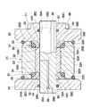
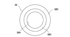
本発明の実施の形態による軸受装置が適用された油圧ショベルを示す正面図である。1 is a front view showing a hydraulic excavator to which a bearing device according to an embodiment of the present invention is applied. 軸受装置を図1中の矢示II−II方向からみた拡大断面図である。It is the expanded sectional view which looked at the bearing apparatus from the arrow II-II direction in FIG. 図2中のOリングと環状シール体とを分解した状態で示す拡大断面図である。FIG. 3 is an enlarged cross-sectional view showing an O-ring and an annular seal body in FIG. 2 in an exploded state. 図3中の環状シール体を右側からみた右側面図である。It is the right view which looked at the annular seal body in FIG. 3 from the right side.

以下、本発明の実施の形態による軸受装置を、油圧ショベルのアームとアームシリンダとのピン結合部に適用した場合を例に挙げ、添付図面の図1ないし図4に従って詳細に説明する。なお、実施の形態では、連結ピンを用いてボス部材を回動可能に連結する相手方部材の代表例として、アームに設けられるブラケット部材を例に挙げて説明する。   Hereinafter, a bearing device according to an embodiment of the present invention will be described in detail with reference to FIGS. 1 to 4 of the accompanying drawings, taking as an example a case where the bearing device is applied to a pin coupling portion between an arm and an arm cylinder of a hydraulic excavator. In the embodiment, a bracket member provided on an arm will be described as an example as a representative example of a counterpart member that rotatably connects a boss member using a connection pin.

図中、1は建設機械としての油圧ショベルで、該油圧ショベル1は、下部走行体2と、該下部走行体2上に旋回可能に搭載された上部旋回体3とにより構成されている。この上部旋回体3は、旋回フレーム4を有し、該旋回フレーム4上には、キャブ5およびカウンタウエイト6等が設けられている。   In the figure, reference numeral 1 denotes a hydraulic excavator as a construction machine, and the hydraulic excavator 1 is composed of a lower traveling body 2 and an upper revolving body 3 that is pivotably mounted on the lower traveling body 2. The upper swing body 3 includes a swing frame 4 on which a cab 5 and a counterweight 6 are provided.

7は上部旋回体3の前部側に俯仰動可能に設けられた作業装置で、この作業装置7は、上部旋回体3の旋回フレーム4前部側にピン結合されたブーム8と、ブーム8の先端側にピン結合されたアーム9と、アーム9の先端側にピン結合された作業具としてのバケット10とを含んで構成されている。作業装置7は、ブーム8がブームシリンダ11によって上,下に俯仰動され、アーム9はアームシリンダ12によりブーム8に対して俯仰動される。また、バケット10はバケットシリンダ13によりリンク14,15を介して回動されるものである。   7 is a work device provided on the front side of the upper swing body 3 so as to be able to be lifted and lowered. The work device 7 includes a boom 8 that is pin-coupled to the front side of the swing frame 4 of the upper swing body 3, and a boom 8. The arm 9 is pin-coupled to the distal end side of the arm 9 and the bucket 10 is a working tool pin-coupled to the distal end side of the arm 9. In the work device 7, the boom 8 is moved up and down by the boom cylinder 11, and the arm 9 is moved up and down with respect to the boom 8 by the arm cylinder 12. The bucket 10 is rotated by the bucket cylinder 13 via the links 14 and 15.

ここで、作業装置7のうち、アーム9の基端側とアームシリンダ12のロッド先端側との間には、例えば図2に示すように、ピン結合部を構成する軸受装置21が装備されている。そして、この軸受装置21は、後述のボス部材22、ブッシュ23、ブラケット部材24,25、連結ピン26およびフローティングシール31を含んで構成されている。   Here, in the working device 7, between the base end side of the arm 9 and the rod distal end side of the arm cylinder 12, for example, as shown in FIG. Yes. The bearing device 21 includes a boss member 22, a bush 23, bracket members 24 and 25, a connecting pin 26, and a floating seal 31 which will be described later.

22はアームシリンダ12のロッド先端側に設けられた筒状のボス部材で、該ボス部材22には、その内周側に後述のブッシュ23が嵌合されるブッシュ嵌合穴22Aと、該ブッシュ嵌合穴22の軸方向両側に位置し断面L字状の切欠き溝からなる左,右一対のシール収容溝22Bとが設けられている。該各シール収容溝22Bは、ボス部材22の軸方向両端側に開口し、外径寸法がブッシュ嵌合穴22Aよりも大径となった拡径穴部として形成されている。   Reference numeral 22 denotes a cylindrical boss member provided on the rod tip side of the arm cylinder 12, and the boss member 22 has a bush fitting hole 22A into which a bush 23 described later is fitted on the inner peripheral side thereof, and the bush. A pair of left and right seal housing grooves 22B, which are notched grooves having an L-shaped cross section and are located on both axial sides of the fitting hole 22, are provided. Each of the seal housing grooves 22B is formed as a diameter-expanded hole portion that opens to both ends in the axial direction of the boss member 22 and has an outer diameter dimension larger than that of the bush fitting hole 22A.

また、ボス部材22の外周側には、軸方向の両側に位置して斜めに傾斜した左,右一対の面取り部22Cが形成されている。これらの各面取り部22Cには、後述するブラケット部材24,25の端面24B,25Bとの間に外側シール35,35が締代をもって配置されている。   In addition, a pair of left and right chamfered portions 22 </ b> C are formed on the outer peripheral side of the boss member 22 and are obliquely inclined and located on both sides in the axial direction. In each of the chamfered portions 22C, outer seals 35, 35 are arranged with tightening margins between end surfaces 24B, 25B of bracket members 24, 25 described later.

23はボス部材22のブッシュ嵌合穴22A内に設けられた筒状のブッシュを示し、該ブッシュ23は、ボス部材22のブッシュ嵌合穴22A内に圧入等の手段を用いて嵌着されている。ブッシュ23は、例えば多孔質構造をなす多数の空孔をもった焼結金属材料を用いて形成され、その空孔には潤滑油が含浸されている。また、ブッシュ23の内周側は円形のピン穴23Aとなり、該ピン穴23A内には後述の連結ピン26が摺動可能に挿嵌されている。   Reference numeral 23 denotes a cylindrical bush provided in the bush fitting hole 22A of the boss member 22. The bush 23 is fitted into the bush fitting hole 22A of the boss member 22 by means such as press fitting. Yes. The bush 23 is formed using, for example, a sintered metal material having a large number of pores having a porous structure, and the pores are impregnated with lubricating oil. Further, the inner peripheral side of the bush 23 is a circular pin hole 23A, and a connecting pin 26 described later is slidably inserted into the pin hole 23A.

24,25はボス部材22を左,右両側から挟んで配置される一対の相手方部材として左,右のブラケット部材である。本実施の形態では、ボス部材22に対する相手方部材の代表例として、アーム9の基端側に設けられたブラケット部材24,25を例示している。ここで、該ブラケット部材24,25は、図2に示すようにボス部材22を左,右両側から挟むように配設され、後述の連結ピン26によりボス部材22に対して相対的に回動可能に連結されている。そして、ブラケット部材24,25には、ブッシュ23のピン穴23Aと対応する位置に円形のピン穴24A,25Aが穿設されている。   Reference numerals 24 and 25 denote left and right bracket members as a pair of counterpart members arranged with the boss member 22 sandwiched from both the left and right sides. In the present embodiment, bracket members 24 and 25 provided on the proximal end side of the arm 9 are illustrated as representative examples of the counterpart member with respect to the boss member 22. Here, as shown in FIG. 2, the bracket members 24 and 25 are disposed so as to sandwich the boss member 22 from the left and right sides, and are rotated relative to the boss member 22 by a connecting pin 26 described later. Connected as possible. The bracket members 24 and 25 are provided with circular pin holes 24A and 25A at positions corresponding to the pin holes 23A of the bush 23.

ブラケット部材24,25の内側面は、ボス部材22と軸方向で対向する端面24B,25Bとなり、この端面24B,25Bのうち後述の環状シール体32が摺接する部位は、表面粗さが小さい平滑面として形成されている。また、図2中で右側に位置する他側のブラケット部材25には、軸方向の外側に向けて突出した段付凸部25Cが設けられ、ピン穴25Aは段付凸部25C内を軸方向に貫通して形成されている。さらに、ブラケット部材25の段付凸部25Cには、後述の固定ボルト27が挿通される挿通孔25Dが径方向に穿設されている。   The inner surfaces of the bracket members 24 and 25 are end surfaces 24B and 25B that face the boss member 22 in the axial direction, and a portion of the end surfaces 24B and 25B where an annular seal body 32 described later is slidably contacted is smooth. It is formed as a surface. Further, the other side bracket member 25 located on the right side in FIG. 2 is provided with a stepped convex portion 25C protruding outward in the axial direction, and the pin hole 25A extends in the axial direction in the stepped convex portion 25C. It is formed to penetrate through. Further, an insertion hole 25D through which a fixing bolt 27 described later is inserted is formed in the stepped convex portion 25C of the bracket member 25 in the radial direction.

26はボス部材22をブラケット部材24,25間に連結した連結ピンで、この連結ピン26は、長さ方向中間部がブッシュ23のピン穴23A内に摺動可能に挿嵌され、連結ピン26の両端側は、ブラケット部材24,25のピン穴24A,25A内に挿通されている。連結ピン26の軸方向一側(図2中で左側)の端面には、円形の凹部26Aが形成され、該凹部26Aの奥所側に位置する底部には、後述の給脂ニップル29が着脱可能に螺着されている。   A connecting pin 26 connects the boss member 22 between the bracket members 24, 25. The connecting pin 26 is slidably inserted into the pin hole 23 A of the bush 23 in the lengthwise intermediate portion, and the connecting pin 26. Both end sides of the bracket members 24 and 25 are inserted into pin holes 24A and 25A. A circular recess 26A is formed on the end surface of the connecting pin 26 on one side in the axial direction (left side in FIG. 2), and a greasing nipple 29 described later is attached to and detached from the bottom located on the back side of the recess 26A. It is screwed on as possible.

また、連結ピン26には、ブッシュ23のピン穴23Aと連結ピン26の外周面との間に潤滑油を供給するための給脂通路26Bが形成され、該給脂通路26Bは、凹部26Aの底部側で後述の給脂ニップル29により閉塞されている。一方、連結ピン26の軸方向他側(図2中で右側)には、後述の固定ボルト27が挿通される挿通孔26Cが径方向に穿設されている。この挿通孔26Cは、ブラケット部材25の挿通孔25Dと連結ピン26の周方向で同軸に位置合せされるものである。   Further, the connecting pin 26 is formed with a greasing passage 26B for supplying lubricating oil between the pin hole 23A of the bush 23 and the outer peripheral surface of the connecting pin 26, and the greasing passage 26B is formed in the recess 26A. The bottom side is closed by a greasing nipple 29 described later. On the other hand, on the other axial side of the connecting pin 26 (right side in FIG. 2), an insertion hole 26C through which a fixing bolt 27 described later is inserted is formed in the radial direction. The insertion hole 26 </ b> C is coaxially aligned in the circumferential direction of the insertion hole 25 </ b> D of the bracket member 25 and the connecting pin 26.

27は連結ピン26の抜止めを行う固定部材として固定ボルトで、この固定ボルト27は、図2に示す如くブラケット部材25の挿通孔25Dと連結ピン26の挿通孔26Cとに挿通されている。この状態で固定ボルト27の先端側にはナット28が螺着される。これにより、固定ボルト27は、連結ピン26をブラケット部材24,25に対して抜止め状態に保持すると共に、連結ピン26がブラケット部材24,25に対して相対回転するのを規制し廻止め状態にも保持するものである。   Reference numeral 27 denotes a fixing bolt as a fixing member for preventing the connection pin 26 from being removed. The fixing bolt 27 is inserted into the insertion hole 25D of the bracket member 25 and the insertion hole 26C of the connection pin 26 as shown in FIG. In this state, a nut 28 is screwed onto the distal end side of the fixing bolt 27. As a result, the fixing bolt 27 holds the connecting pin 26 in a state where it is prevented from being pulled out with respect to the bracket members 24, 25, and restricts the connecting pin 26 from rotating relative to the bracket members 24, 25. It is also something that holds.

29は連結ピン26の凹部26A内に設けられた給脂ニップルで、該給脂ニップル29は、凹部26Aの奥所(底部)側に着脱可能に螺着されている。例えばグリースガン等の給脂具(図示せず)を用いてグリース等の潤滑油を給脂する場合には、この給脂具を給脂ニップル29の位置にセットし、この状態で連結ピン26の給脂通路26B内に向けてグリース等の潤滑油を給脂する。このとき給脂油は、給脂通路26B内に加圧状態で押し出され、ブッシュ23のピン穴23Aと連結ピン26の外周面との間の摺動面に供給される。   Reference numeral 29 denotes a greasing nipple provided in the recess 26A of the connecting pin 26. The greasing nipple 29 is detachably screwed to the back (bottom) side of the recess 26A. For example, when lubricating oil such as grease is supplied using a greasing tool (not shown) such as a grease gun, the greasing tool is set at the position of the greasing nipple 29, and in this state, the connecting pin 26 Lubricating oil such as grease is supplied into the oil supply passage 26B. At this time, the oil supply oil is pushed out into the oil supply passage 26B in a pressurized state and supplied to the sliding surface between the pin hole 23A of the bush 23 and the outer peripheral surface of the connecting pin 26.

30,30はブラケット部材24,25と連結ピン26との間をシールする左,右一対のシール部材で、該各シール部材30のうち一方のシール部材30は、ブラケット部材24のピン穴24Aと連結ピン26の外周面との間に配置され、両者の間に外部からの異物が侵入するのを防ぐと共に、前記潤滑油(給脂油)が両者の間から軸方向外側に向けて漏出するのを防ぐ。また、他方のシール部材30は、ブラケット部材25のピン穴25Aと連結ピン26の外周面との間に配置され、両者の間に外部からの異物が侵入するのを防ぐと共に、前記潤滑油(給脂油)が両者の間から軸方向外側に向けて漏出するのを防ぐものである。   30 and 30 are a pair of left and right seal members that seal between the bracket members 24 and 25 and the connecting pin 26, and one of the seal members 30 is connected to the pin hole 24A of the bracket member 24. It is arranged between the outer peripheral surface of the connecting pin 26 and prevents foreign matter from entering between them, and the lubricating oil (grease oil) leaks out between the two in the axial direction. prevent. The other seal member 30 is disposed between the pin hole 25A of the bracket member 25 and the outer peripheral surface of the connecting pin 26, and prevents foreign matter from entering between the two, and the lubricating oil ( (Grease oil) is prevented from leaking out between the two in the axial direction.

31,31はブッシュ23の軸方向両端側に位置してボス部材22と連結ピン26との間に設けられた左,右一対のシール手段を構成するフローティングシールである。これらのフローティングシール31は、軸方向で互いに対向するボス部材22の端面側(シール収容溝22B)とブラケット部材24,25の端面24B,25Bとの間を浮動状態でシールするものである。即ち、各フローティングシール31は、連結ピン26の外周側に隙間をもって挿通される環状シール体32と、該環状シール体32とボス部材22のシール収容溝22Bとの間に弾性変形状態で配置されるOリング33とにより構成されている。   Reference numerals 31 and 31 denote floating seals that are located on both axial ends of the bush 23 and constitute a pair of left and right sealing means provided between the boss member 22 and the connecting pin 26. These floating seals 31 seal the space between the end surface sides (seal housing grooves 22B) of the boss members 22 facing each other in the axial direction and the end surfaces 24B, 25B of the bracket members 24, 25 in a floating state. That is, each floating seal 31 is arranged in an elastically deformed state between an annular seal body 32 inserted through the outer peripheral side of the connecting pin 26 with a gap and the annular seal body 32 and the seal housing groove 22B of the boss member 22. And an O-ring 33.

左,右のブラケット部材24,25間でボス部材22が連結ピン26の周囲を回動するとき、フローティング31の環状シール体32は、Oリング33により締代が与えられるためボス部材22と一緒に回動し、後述の摺接面部32Dがブラケット部材24,25の端面24B,25Bに対して相対回転するように摺接する。即ち、フローティングシール31は、ボス部材22のシール収容溝22Bと連結ピン26の外周面との間に、環状シール体32をOリング33により浮動状態(フローティング状態)に保持しつつ、後述の如くシール機能を発揮するものである。   When the boss member 22 rotates around the connecting pin 26 between the left and right bracket members 24, 25, the annular seal body 32 of the floating 31 is tightened by the O-ring 33, and therefore, together with the boss member 22. The sliding contact surface portion 32D described later is in sliding contact with the end surfaces 24B and 25B of the bracket members 24 and 25 so as to rotate relative to each other. That is, the floating seal 31 holds the annular seal body 32 in a floating state (floating state) by the O-ring 33 between the seal receiving groove 22B of the boss member 22 and the outer peripheral surface of the connecting pin 26, as described later. It exhibits a sealing function.

ここで、環状シール体32は、例えば鋳鉄、鋼鉄等の金属材料、セラミックスまたは硬質樹脂等の剛性材料を用いて、図2、図3に示すように断面形状が略J字状または略L字状をなすリングとして形成され、その内周側は、連結ピン26の外径よりも大径に形成されたピン挿通穴32Aとなっている。環状シール体32は、ピン挿通穴32Aの軸方向両側に対向面部32Bとテーパ面部32Cとを有し、対向面部32Bは、ブッシュ23の軸方向端面に隙間を介して対向配置される。テーパ面部32Cは、後述の摺接面部32Dとピン挿通穴32Aとの間に斜めに傾斜して形成され、後述の油溜り34がテーパ面部32Cの内側に画成される。   Here, the annular sealing body 32 is made of, for example, a metal material such as cast iron or steel, or a rigid material such as ceramics or hard resin, and the cross-sectional shape is substantially J-shaped or substantially L-shaped as shown in FIGS. It is formed as a ring having a shape, and an inner peripheral side thereof is a pin insertion hole 32 </ b> A formed to have a larger diameter than the outer diameter of the connecting pin 26. The annular seal body 32 has a facing surface portion 32B and a tapered surface portion 32C on both sides in the axial direction of the pin insertion hole 32A, and the facing surface portion 32B is disposed to face the axial end surface of the bush 23 via a gap. The tapered surface portion 32C is formed to be inclined obliquely between a sliding contact surface portion 32D described later and the pin insertion hole 32A, and an oil reservoir 34 described later is defined inside the tapered surface portion 32C.

また、環状シール体32には、テーパ面部32Cの径方向外側に位置する環状の摺接面部32Dと、該環状の摺接面部32Dとは軸方向の反対側で対向面部32Bの径方向外側部位を円弧状に切欠くように形成された環状の凹面部32Eとが設けられている。環状の摺接面部32Dは、弾性変形したOリング33によりブラケット部材24,25の端面24B,25Bに付勢されて該端面24B,25Bに摺接しブラケット部材24,25との間をシールするシール面を構成している。   The annular seal body 32 includes an annular sliding contact surface portion 32D positioned on the radially outer side of the tapered surface portion 32C, and a radially outer portion of the opposing surface portion 32B on the opposite side of the annular sliding contact surface portion 32D in the axial direction. And an annular concave surface portion 32E formed so as to be cut out in an arc shape. The annular slidable contact surface portion 32D is urged against the end surfaces 24B and 25B of the bracket members 24 and 25 by the elastically deformed O-ring 33 to slidably contact the end surfaces 24B and 25B and seal between the bracket members 24 and 25. Make up surface.

環状シール体32の凹面部32Eは、図3に示すように斜めに傾いた円弧状の凹湾曲面として形成され、ボス部材22のシール収容溝22Bとの間でOリング33を斜め方向から挟み込んで弾性変形状態に保持する構成となっている。このとき、弾性変形したOリング33は、環状シール体32の凹面部32Eに広く面接触することにより斜めに傾いた状態となり、ボス部材22のシール収容溝22Bに対しても締代をもって接触した状態に保持される。   As shown in FIG. 3, the concave surface portion 32 </ b> E of the annular seal body 32 is formed as an arcuate concave curved surface inclined obliquely, and sandwiches the O-ring 33 between the boss member 22 and the seal housing groove 22 </ b> B from an oblique direction. The structure is held in an elastically deformed state. At this time, the elastically deformed O-ring 33 is in a state of being inclined obliquely by making wide surface contact with the concave surface portion 32E of the annular seal body 32, and is also in contact with the seal housing groove 22B of the boss member 22 with tightening allowance. Kept in a state.

これによって、ボス部材22のシール収容溝22Bと環状シール体32との間は、締代をもったOリング33により安定したシール状態に保たれる。また、ブラケット部材24,25の端面24B,25Bと環状シール体32との間は、環状の摺接面部32Dが端面24B,25Bに摺接することにより両者の間をシール状態に保つ。この結果、ボス部材22の軸方向両側とブラケット部材24,25の端面24B,25Bとの間は、環状シール体32とOリング33からなるフローティングシール31により浮動状態でシールされ、内部の潤滑油が外部に漏洩するのを防ぐと共に、異物の侵入に対しても後述の外側シール35と一緒にシール機能が発揮されるものである。   Thus, a stable seal state is maintained between the seal housing groove 22B of the boss member 22 and the annular seal body 32 by the O-ring 33 having a tightening allowance. Further, between the end surfaces 24B and 25B of the bracket members 24 and 25 and the annular seal body 32, the annular sliding contact surface portion 32D is in sliding contact with the end surfaces 24B and 25B, thereby maintaining a sealed state therebetween. As a result, the axially opposite sides of the boss member 22 and the end surfaces 24B and 25B of the bracket members 24 and 25 are sealed in a floating state by the floating seal 31 including the annular seal body 32 and the O-ring 33, and the internal lubricating oil Is prevented from leaking to the outside, and a sealing function is exerted together with an outer seal 35 described later against entry of foreign matter.

34,34は連結ピン26の外周側に位置してブラケット部材24,25の端面24B,25Bと各環状シール体32との間に画成された油溜りである。この油溜り34は、環状シール体32のテーパ面部32Cによりブラケット部材24,25の端面24B,25Bと連結ピン26との間に略三角形状をなす空隙として形成され、その内部には前記給脂油の一部等が溜められるものである。   34 and 34 are oil reservoirs that are located on the outer peripheral side of the connecting pin 26 and defined between the end surfaces 24B and 25B of the bracket members 24 and 25 and the respective annular seal bodies 32. The oil reservoir 34 is formed as a substantially triangular gap between the end surfaces 24B, 25B of the bracket members 24, 25 and the connecting pin 26 by the tapered surface portion 32C of the annular seal body 32, and the oil supply oil is contained therein. A part of this is stored.

35,35はボス部材22の各面取り部22Cとブラケット部材24,25の端面24B,25Bとの間に外側から装着された外側シールである。これらの外側シール35は、例えばOリングを用いて形成され、フローティングシール31の径方向外側に位置してボス部材22とブラケット部材24,25との間の隙間内に外部のダスト等が侵入するのを防ぐものである。   Reference numerals 35 and 35 denote outer seals mounted from the outside between the chamfered portions 22C of the boss member 22 and the end surfaces 24B and 25B of the bracket members 24 and 25, respectively. These outer seals 35 are formed by using, for example, O-rings, and are located outside in the radial direction of the floating seal 31 so that external dust or the like enters the gap between the boss member 22 and the bracket members 24 and 25. Is to prevent

本実施の形態による油圧ショベル1に適用された軸受装置21は、上述の如き構成を有するもので、油圧ショベル1の作業装置7により土砂等の掘削作業を行うときには、アームシリンダ12のロッド先端側に軸受装置21を介してピン結合されたアーム9の基端側が、アームシリンダ12の伸縮動作に応じて連結ピン26を中心として回動動作を行う。即ち、左,右のブラケット部材24,25間でボス部材22がブッシュ23と一緒に連結ピン26の周囲を回動するように相対変位する。   The bearing device 21 applied to the hydraulic excavator 1 according to the present embodiment has the above-described configuration. When excavation work such as earth and sand is performed by the working device 7 of the hydraulic excavator 1, the rod tip side of the arm cylinder 12 is used. The base end side of the arm 9 that is pin-coupled via the bearing device 21 rotates around the connecting pin 26 according to the expansion / contraction operation of the arm cylinder 12. That is, the boss member 22 is relatively displaced between the left and right bracket members 24 and 25 so as to rotate around the connecting pin 26 together with the bush 23.

そして、アーム9の回動時にはブッシュ23と連結ピン26との間の摩擦熱等によりブッシュ23に含浸した潤滑油の粘度が下がるために、ブッシュ23の内部からブッシュ23と連結ピン26との摺動面にしみ出すようになり、この潤滑油によってブッシュ23と連結ピン26との摺動面に油膜を形成することができる。また、油圧ショベル1のメンテナンス時には、例えばグリースガン等の給脂具を用いて連結ピン26の給脂通路26B内に潤滑油を供給でき、これによってもブッシュ23と連結ピン26との摺動面を潤滑状態に保つことができる。   When the arm 9 rotates, the viscosity of the lubricating oil impregnated in the bush 23 decreases due to frictional heat between the bush 23 and the connecting pin 26, and therefore the sliding between the bush 23 and the connecting pin 26 from the inside of the bush 23 occurs. The oil oozes out to the moving surface, and an oil film can be formed on the sliding surface between the bush 23 and the connecting pin 26 by this lubricating oil. Further, during maintenance of the hydraulic excavator 1, for example, a lubricating oil such as a grease gun can be used to supply lubricating oil into the greasing passage 26B of the connecting pin 26, and this also causes the sliding surface between the bush 23 and the connecting pin 26 to be supplied. Can be kept in a lubricated state.

ここで、本実施の形態では、連結ピン26の外周側でボス部材22の各シール収容溝22Bとブラケット部材24,25の端面24B,25Bとの間には、環状シール体32とOリング33とからなるフローティングシール31を設ける構成としている。前記環状シール体32は、ブラケット部材24,25の端面24B,25Bに摺接しブラケット部材24,25との間をシールする環状の摺接面部32Dと、該環状の摺接面部32とは軸方向の反対側に形成されボス部材22のシール収容溝22Bとの間でOリング33を弾性変形状態に保持する環状の凹面部32Eとを有している。   Here, in the present embodiment, an annular seal body 32 and an O-ring 33 are provided between the seal housing grooves 22B of the boss member 22 and the end faces 24B, 25B of the bracket members 24, 25 on the outer peripheral side of the connecting pin 26. It is set as the structure which provides the floating seal 31 which consists of these. The annular seal body 32 includes an annular slidable contact surface portion 32D that is in sliding contact with the end surfaces 24B and 25B of the bracket members 24 and 25 and seals between the bracket members 24 and 25, and the annular slidable contact surface portion 32 is in the axial direction. And an annular concave portion 32E that holds the O-ring 33 in an elastically deformed state between the boss member 22 and the seal housing groove 22B.

これにより、フローティングシール31は、ボス部材22のシール収容溝22Bと連結ピン26の外周面との間に、環状シール体32をOリング33により浮動状態(フローティング状態)に保持しつつ、弾性変形したOリング33の付勢力により環状の摺接面部32Dをブラケット部材24(25)の端面24B(25B)に摺接させることができ、この摺接面をシール状態に保つことができる。   Accordingly, the floating seal 31 is elastically deformed while the annular seal body 32 is held in a floating state (floating state) by the O-ring 33 between the seal housing groove 22B of the boss member 22 and the outer peripheral surface of the connecting pin 26. The annular sliding contact surface portion 32D can be brought into sliding contact with the end surface 24B (25B) of the bracket member 24 (25) by the biasing force of the O-ring 33, and the sliding contact surface can be kept in a sealed state.

このため、ボス部材22とブラケット部材24,25とが連結ピン26を介して相対的に回動するときに、フローティングシール31の環状シール体32に働く摺動抵抗を小さく抑え、エネルギ損失を低減することができる。しかも、環状シール体32の摺接面部32Dによりブラケット部材24(25)の端面24B(25B)との間をシールでき、Oリング33によりボス部材22のシール収容溝22Bとの間をシールすることができる。   For this reason, when the boss member 22 and the bracket members 24 and 25 are rotated relative to each other via the connecting pin 26, the sliding resistance acting on the annular seal body 32 of the floating seal 31 is suppressed to reduce energy loss. can do. In addition, the space between the end surface 24B (25B) of the bracket member 24 (25) can be sealed by the sliding contact surface portion 32D of the annular seal body 32, and the space between the seal housing groove 22B of the boss member 22 can be sealed by the O-ring 33. Can do.

従って、本実施の形態によれば、フローティングシール31を採用することにより、外部からの異物がブッシュ23と連結ピン26との間に侵入するのを防止できると共に、ブッシュ23と連結ピン26との間に供給(給脂)した潤滑油が外部に漏洩するのを防止することができ、潤滑油の給脂間隔を長くすることができる。   Therefore, according to the present embodiment, by adopting the floating seal 31, it is possible to prevent foreign matters from entering between the bush 23 and the connecting pin 26, and between the bush 23 and the connecting pin 26. It is possible to prevent the lubricating oil supplied (greased) in the meantime from leaking to the outside, and to increase the lubrication interval of the lubricating oil.

また、本実施の形態によると、ブッシュ23の軸方向両端側に位置してボス部材22の内周側には一対のシール収容溝22Bを設け、環状シール体32の凹面部32Eは、図3に示すように斜めに傾いた円弧状の凹湾曲面として形成され、ボス部材22のシール収容溝22Bとの間でOリング33を斜め方向から挟み込んで弾性変形状態に保持する構成としている。   Further, according to the present embodiment, the pair of seal housing grooves 22B are provided on the inner peripheral side of the boss member 22 located on both ends in the axial direction of the bush 23, and the concave surface portion 32E of the annular seal body 32 is shown in FIG. As shown in FIG. 3, the O-ring 33 is sandwiched from the oblique direction between the boss member 22 and the seal housing groove 22B and held in an elastically deformed state.

これにより、弾性的に撓み変形したOリング33は、環状シール体32の凹面部32Eに広く面接触することにより斜めに傾いた状態となり、ボス部材22のシール収容溝22Bに対しても締代をもって接触した状態に保持される。この結果、ボス部材22のシール収容溝22Bと環状シール体32との間は、締代をもったOリング33により安定したシール状態に保つことができ、ブラケット部材24,25の端面24B,25Bと環状シール体32との間は、環状の摺接面部32Dが端面24B,25Bに摺接することにより両者の間をシール状態に保つことができる。   As a result, the O-ring 33 that is elastically bent and deformed is in a state of being inclined obliquely by making wide surface contact with the concave surface portion 32E of the annular seal body 32, and is also tightened with respect to the seal housing groove 22B of the boss member 22. Is held in contact. As a result, a stable sealing state can be maintained between the seal housing groove 22B of the boss member 22 and the annular seal body 32 by the O-ring 33 having a tightening allowance, and the end surfaces 24B, 25B of the bracket members 24, 25 are secured. The annular slidable contact surface portion 32D is in slidable contact with the end surfaces 24B and 25B so that the sealed state between the two can be maintained.

このため、ボス部材22の軸方向両側端面とブラケット部材24,25の端面24B,25Bとの間は、環状シール体32とOリング33からなるフローティングシール31により安定してシールすることができ、内部の潤滑油が外部に漏洩するのを防ぐことができる。また、外部からの異物侵入に対しては、外側シール35とフローティングシール31とにより二重のシール機能を発揮することができる。   For this reason, between the axial direction both side end surfaces of the boss member 22 and the end surfaces 24B, 25B of the bracket members 24, 25 can be stably sealed by the floating seal 31 including the annular seal body 32 and the O-ring 33, The internal lubricating oil can be prevented from leaking to the outside. Further, with respect to the entry of foreign matter from the outside, the double seal function can be exhibited by the outer seal 35 and the floating seal 31.

さらに、ブラケット部材24,25のピン穴24A,25Aと連結ピン26との間には、例えばOリング等により構成される左,右のシール部材30を設けているので、これらのシール部材30により両者の間に外部からの異物が侵入するのを防ぐことができると共に、例えば油溜り34内の潤滑油(給脂油)が両者の間から軸方向外側に向けて漏出するのを防ぐことができる。   Further, between the pin holes 24A, 25A of the bracket members 24, 25 and the connecting pin 26, left and right seal members 30 constituted by, for example, O-rings are provided. It is possible to prevent foreign matters from entering between the two, and for example, it is possible to prevent the lubricating oil (greased oil) in the oil reservoir 34 from leaking out between the two in the axial direction. .

なお、前記実施の形態では、作業装置7に用いる複数の軸受装置のうち、アーム9の基端側とアームシリンダ12のロッド先端側との間に設ける軸受装置21を例に挙げて説明した。しかし、本発明はこれに限るものではなく、例えばアームシリンダ12のボトム側とブーム8側の間に用いる軸受装置、ブームシリンダ11またはバケットシリンダ13に用いる軸受装置に適用してもよい。また、作業装置7のアーム9とバケット10との間に用いる軸受装置、ブーム8の先端とアーム9との間に用いる軸受装置、ブーム8のフート部と旋回フレーム4との間に用いる軸受装置に適用してもよい。   In the embodiment, the bearing device 21 provided between the base end side of the arm 9 and the rod tip end side of the arm cylinder 12 among the plurality of bearing devices used in the working device 7 has been described as an example. However, the present invention is not limited to this, and may be applied to a bearing device used between the bottom side of the arm cylinder 12 and the boom 8 side, a bearing device used for the boom cylinder 11 or the bucket cylinder 13, for example. Further, a bearing device used between the arm 9 and the bucket 10 of the working device 7, a bearing device used between the tip of the boom 8 and the arm 9, and a bearing device used between the foot portion of the boom 8 and the swing frame 4. You may apply to.

この場合、連結ピンを用いてボス部材に連結される相手方部材は、前記実施の形態で述べたように左,右のブラケット部材24,25に限るものではなく、例えば図1に示すアームシリンダ12のボトム側の取付アイ(ボス部材)に対する相手方部材は、ブーム8に設けた左,右一対のブラケットとなる。また、図1に示すバケットシリンダ13のボトム側の取付アイ(ボス部材)に対する相手方部材は、アーム9に設けた左,右一対のブラケットとなる。さらに、例えば図14に示すリンク14,15の端部(連結ピンが取付けられる端部)も相手方部材となるものである。   In this case, the counterpart member connected to the boss member using the connecting pin is not limited to the left and right bracket members 24 and 25 as described in the above embodiment, and for example, the arm cylinder 12 shown in FIG. The counterpart member for the bottom mounting eye (boss member) is a pair of left and right brackets provided on the boom 8. 1 is a pair of left and right brackets provided on the arm 9 with respect to the mounting eye (boss member) on the bottom side of the bucket cylinder 13 shown in FIG. Furthermore, for example, end portions (end portions to which the connecting pins are attached) of the links 14 and 15 shown in FIG. 14 also serve as counterpart members.

さらに、前記実施の形態では、軸受装置を油圧ショベルに適用した場合を例に挙げて説明した。しかし、本発明はこれに限らず、例えば油圧クレーン、ホイールローダ、ブルドーザ等の他の建設機械で用いる軸受装置にも広く適用できるものである。   Further, in the above embodiment, the case where the bearing device is applied to a hydraulic excavator has been described as an example. However, the present invention is not limited to this, and can be widely applied to bearing devices used in other construction machines such as a hydraulic crane, a wheel loader, and a bulldozer.

1 油圧ショベル
7 作業装置
8 ブーム
9 アーム
10 バケット(作業具)
11 ブームシリンダ
12 アームシリンダ
13 バケットシリンダ(作業具シリンダ)
21 軸受装置
22 ボス部材
22A ブッシュ嵌合穴
22B シール収容溝
23 ブッシュ
23A,24A,25A ピン穴
24,25 ブラケット部材(相手方部材)
24B,25B 端面
26 連結ピン
31 フローティングシール(シール手段)
32 環状シール体
32A ピン挿通穴
32B 対向面部
32C テーパ面部
32D 摺接面部
32E 凹面部
33 Oリング
34 油溜り
35 外側シール
1 Hydraulic Excavator 7 Working Device 8 Boom 9 Arm 10 Bucket (Working Tool)
11 Boom cylinder 12 Arm cylinder 13 Bucket cylinder (work implement cylinder)
21 Bearing device 22 Boss member 22A Bushing fitting hole 22B Seal receiving groove 23 Bushing 23A, 24A, 25A Pin hole 24, 25 Bracket member (counter member)
24B, 25B End face 26 Connecting pin 31 Floating seal (sealing means)
32 annular seal body 32A pin insertion hole 32B opposing surface portion 32C taper surface portion 32D sliding contact surface portion 32E concave surface portion 33 O-ring 34 oil reservoir 35 outer seal

Claims (2)

内周側にブッシュが嵌着して設けられたボス部材と、前記ブッシュの内周側に挿通され前記ボス部材を相手方部材に回動可能に連結する連結ピンと、前記ブッシュの軸方向両端側に位置して前記ボス部材と連結ピンとの間に設けられたシール手段とを備えてなる軸受装置において、
前記シール手段は、軸方向で互いに対向する前記ボス部材の端面と前記相手方部材の端面との間を浮動状態でシールするフローティングシールにより構成し、
該フローティングシールは、前記連結ピンの外周側に挿通され前記相手方部材の端面に摺接して前記相手方部材との間をシールする環状シール体と、該環状シール体と前記ボス部材との間をシールするため該環状シール体と前記ボス部材との間に弾性変形状態で配置され該環状シール体を前記相手方部材の端面に向けて弾性的に付勢するOリングとを備える構成としたことを特徴とする軸受装置。
A boss member fitted with a bush on the inner peripheral side, a connecting pin that is inserted into the inner peripheral side of the bush and pivotally connects the boss member to a counterpart member, and both axial ends of the bush In a bearing device comprising a sealing means located between the boss member and the connecting pin,
The sealing means is constituted by a floating seal that seals in a floating state between an end surface of the boss member and an end surface of the counterpart member facing each other in the axial direction,
The floating seal is inserted into the outer peripheral side of the connecting pin, and an annular seal body that is in sliding contact with the end surface of the counterpart member and seals between the counterpart member, and a seal between the annular seal body and the boss member Therefore, an O-ring that is arranged in an elastically deformed state between the annular seal body and the boss member and elastically biases the annular seal body toward the end surface of the counterpart member is provided. Bearing device.
前記環状シール体は、前記相手方部材の端面に摺接し前記相手方部材との間をシールする環状の摺接面部と、該環状の摺接面部とは軸方向の反対側に形成され前記ボス部材との間で前記Oリングを弾性変形状態に保持する環状の凹面部とを有する構成としてなる請求項1に記載の軸受装置。   The annular seal body includes an annular slide contact surface portion that is in sliding contact with an end surface of the counterpart member and seals between the counterpart member, and the annular slide contact surface portion is formed on the opposite side in the axial direction from the boss member. The bearing device according to claim 1, further comprising an annular concave surface portion that holds the O-ring in an elastically deformed state.
JP2011071977A 2011-03-29 2011-03-29 Bearing device Expired - Fee Related JP5558397B2 (en)

Priority Applications (1)

Application Number Priority Date Filing Date Title
JP2011071977A JP5558397B2 (en) 2011-03-29 2011-03-29 Bearing device

Applications Claiming Priority (1)

Application Number Priority Date Filing Date Title
JP2011071977A JP5558397B2 (en) 2011-03-29 2011-03-29 Bearing device

Publications (2)

Publication Number Publication Date
JP2012207689A true JP2012207689A (en) 2012-10-25
JP5558397B2 JP5558397B2 (en) 2014-07-23

Family

ID=47187610

Family Applications (1)

Application Number Title Priority Date Filing Date
JP2011071977A Expired - Fee Related JP5558397B2 (en) 2011-03-29 2011-03-29 Bearing device

Country Status (1)

Country Link
JP (1) JP5558397B2 (en)

Cited By (1)

* Cited by examiner, † Cited by third party
Publication number Priority date Publication date Assignee Title
CN109208683A (en) * 2018-10-30 2019-01-15 三重机有限公司 Pivoting support Huang oil pool sealing structure and excavator

Citations (2)

* Cited by examiner, † Cited by third party
Publication number Priority date Publication date Assignee Title
JPS541753A (en) * 1977-06-03 1979-01-08 Teijin Seiki Co Ltd Seal mechanism
JPH051015U (en) * 1991-06-26 1993-01-08 油谷重工株式会社 Pin coupling device

Patent Citations (2)

* Cited by examiner, † Cited by third party
Publication number Priority date Publication date Assignee Title
JPS541753A (en) * 1977-06-03 1979-01-08 Teijin Seiki Co Ltd Seal mechanism
JPH051015U (en) * 1991-06-26 1993-01-08 油谷重工株式会社 Pin coupling device

Cited By (2)

* Cited by examiner, † Cited by third party
Publication number Priority date Publication date Assignee Title
CN109208683A (en) * 2018-10-30 2019-01-15 三重机有限公司 Pivoting support Huang oil pool sealing structure and excavator
CN109208683B (en) * 2018-10-30 2023-08-22 三一重机有限公司 Slewing bearing Huang Youchi sealing structure and excavator

Also Published As

Publication number Publication date
JP5558397B2 (en) 2014-07-23

Similar Documents

Publication Publication Date Title
JP5172444B2 (en) Bearing device
US6783129B2 (en) Sealing device
US9623920B2 (en) Track joint assemblies
CN104053840A (en) Bearing device for construction machine
CN101091067A (en) Bearing device
US9604681B2 (en) Track joint assemblies
US9505453B2 (en) Track joint assemblies
CN101002042A (en) Two component pin seal
US9656707B2 (en) High speed metal face seal
JP5558397B2 (en) Bearing device
JP4988642B2 (en) Bearing device
JP2017532242A (en) Track seal assembly for greased hydraulic excavators
JPH0932844A (en) Bearing device
KR20130092010A (en) Linkage structure for bucket and arm of hydraulic excavator
JP2003176815A (en) Bearing device
JP2008075382A (en) Bearing device
JPH10311335A (en) Bearing device
JP2005214266A (en) Bearing device
JP3251859B2 (en) Bearing device
JPH11148560A (en) Bearing seal device for front of construction machine
JP2000038739A (en) Two member connecting device for construction equipment
JPH10311334A (en) Bearing for construction machine
JPH09111804A (en) Bearing device
JPH11131526A (en) Bearing device
JPH11141549A (en) Two-member coupling device of constrution machine

Legal Events

Date Code Title Description
A621 Written request for application examination

Free format text: JAPANESE INTERMEDIATE CODE: A621

Effective date: 20130215

A977 Report on retrieval

Free format text: JAPANESE INTERMEDIATE CODE: A971007

Effective date: 20131108

A131 Notification of reasons for refusal

Free format text: JAPANESE INTERMEDIATE CODE: A131

Effective date: 20131119

A521 Request for written amendment filed

Free format text: JAPANESE INTERMEDIATE CODE: A523

Effective date: 20131226

TRDD Decision of grant or rejection written
A01 Written decision to grant a patent or to grant a registration (utility model)

Free format text: JAPANESE INTERMEDIATE CODE: A01

Effective date: 20140603

A61 First payment of annual fees (during grant procedure)

Free format text: JAPANESE INTERMEDIATE CODE: A61

Effective date: 20140604

R150 Certificate of patent or registration of utility model

Ref document number: 5558397

Country of ref document: JP

Free format text: JAPANESE INTERMEDIATE CODE: R150

LAPS Cancellation because of no payment of annual fees