JP2012207828A - Vertical baking furnace - Google Patents
Vertical baking furnace Download PDFInfo
- Publication number
- JP2012207828A JP2012207828A JP2011072431A JP2011072431A JP2012207828A JP 2012207828 A JP2012207828 A JP 2012207828A JP 2011072431 A JP2011072431 A JP 2011072431A JP 2011072431 A JP2011072431 A JP 2011072431A JP 2012207828 A JP2012207828 A JP 2012207828A
- Authority
- JP
- Japan
- Prior art keywords
- firing
- space
- furnace
- cylinder
- hearth
- Prior art date
- Legal status (The legal status is an assumption and is not a legal conclusion. Google has not performed a legal analysis and makes no representation as to the accuracy of the status listed.)
- Granted
Links
Images
Landscapes
- Furnace Details (AREA)
- Vertical, Hearth, Or Arc Furnaces (AREA)
Abstract
【課題】処理能力を増大しても炉本体の高さを大きくすることなく、十分に焼成のための熱を原料へ与える竪型焼成炉を提供することを課題とする。
【解決手段】炉床11より上方で予熱空間を形成する予熱筒体12と炉床11より下方で焼成空間を形成する焼成筒体13を有し、予熱空間は炉蓋より下方に落下開口11Aを有する炉床の外周縁より上方に延びる予熱筒体12の空間内に形成され、焼成空間が炉床11の落下開口11Aの周縁より下方に延びる焼成筒体13の空間内に形成され、炉蓋14に、予熱空間へ向け燃焼ガスもしくは高温ガスを噴射する加熱装置15が設けられ、焼成筒体13は、高さ方向中間位置で、焼成筒体13の内面から半径内方に延びる障壁部13Aが周方向の複数位置に設けられていると共に、焼成筒体13の周壁に、障壁部13Aの直下に生ずる空間へ燃焼ガスもしくは高温ガスを噴射する副加熱装置20が設けられている。
【選択図】図1An object of the present invention is to provide a vertical firing furnace that sufficiently supplies heat for firing to a raw material without increasing the height of the furnace body even when the processing capacity is increased.
SOLUTION: A preheating cylinder 12 that forms a preheating space above the hearth 11 and a firing cylinder 13 that forms a baking space below the hearth 11 are provided, and the preheating space has a drop opening 11A below the furnace lid. And the firing space is formed in the space of the firing cylinder 13 extending downward from the periphery of the drop opening 11A of the hearth 11, and the furnace The lid 14 is provided with a heating device 15 for injecting combustion gas or high-temperature gas toward the preheating space, and the firing cylinder 13 is a barrier portion extending radially inward from the inner surface of the firing cylinder 13 at an intermediate position in the height direction. 13A is provided at a plurality of positions in the circumferential direction, and a sub-heating device 20 that injects combustion gas or high-temperature gas into a space formed directly below the barrier portion 13A is provided on the peripheral wall of the firing cylinder 13.
[Selection] Figure 1
Description
本発明は、竪型焼成炉に関する。 The present invention relates to a vertical firing furnace.
この種の焼成炉としては、特許文献1に開示されているものが知られている。 As this type of firing furnace, one disclosed in Patent Document 1 is known.
特許文献1の竪型焼成炉は、炉床より上方で予熱空間を形成する予熱筒体と炉床より下方で焼成空間を形成する焼成筒体を有する竪型筒状の炉体を備えた竪型焼成炉において、予熱空間は加熱装置が設けられている炉蓋より下方で炉体内面から半径内方に延び中央部に落下開口を有する炉床の外周縁より上方に延びて設けられた予熱筒体の空間内に形成され、焼成空間が該炉床の落下開口の周縁より下方に延びる焼成筒体の空間内に形成されている。 The vertical firing furnace of Patent Document 1 includes a vertical tubular furnace body having a preheating cylinder body that forms a preheating space above the hearth and a firing cylinder body that forms a firing space below the hearth. In the mold firing furnace, the preheating space is provided below the furnace lid provided with the heating device, extending inwardly from the inner surface of the furnace body and extending above the outer peripheral edge of the hearth having a drop opening at the center. A firing space is formed in the space of the cylindrical body, and the firing space extends downward from the periphery of the drop opening of the hearth.
上記炉蓋の中央軸線位置には、上記予熱空間に向け燃焼ガスを噴射するバーナが設けられており、上記焼成筒体は、高さ方向中間位置で、該焼成筒体の内面から半径内方に延びるブリッジが周方向の複数位置に設けられている。該複数のブリッジは、焼成筒体の中央軸線位置で連結されている。 A burner for injecting combustion gas toward the preheating space is provided at the central axis position of the furnace lid, and the firing cylinder is located at an intermediate position in the height direction from the inner surface of the firing cylinder. Are provided at a plurality of positions in the circumferential direction. The plurality of bridges are connected at the central axis position of the firing cylinder.
このような特許文献1の竪型焼成炉では、炉床上の原料は上記燃焼ガスに面する表層で予熱され、炉床の上方に設けられたプッシャで半径内方へ押し出されて上記落下開口から焼成筒体の焼成空間内へ落下する。上記炉床の落下開口から落下して焼成空間で堆積された原料の堆積層では、原料は自己が保有する熱により、この堆積層内で焼成が促進される。焼成が進行した原料は、上記焼成空間を上昇する冷却空気と接触して冷却されながら降下して、焼成筒体の下部に設けられた排出筒から製品として排出される。 In such a vertical firing furnace of Patent Document 1, the raw material on the hearth is preheated on the surface layer facing the combustion gas, and is pushed out radially inward by a pusher provided above the hearth from the drop opening. It falls into the firing space of the firing cylinder. In the deposited layer of the raw material dropped from the drop opening of the hearth and deposited in the firing space, firing of the raw material is promoted in the deposited layer by the heat held by itself. The raw material that has been baked contacts the cooling air that rises in the calcination space and descends while being cooled, and is discharged as a product from a discharge tube provided in the lower portion of the calcination tube.
しかしながら、特許文献1の竪型焼成炉にあっては、構造上そして機能上において改善すべき余地があった。 However, the vertical firing furnace of Patent Document 1 has room for improvement in structure and function.
特許文献1に開示されている種の竪型焼成炉は、原料の処理能力を増大させようとすると、その分、加熱焼成時間を長くせねばならず、炉体の高さが大きくなってしまう。また、炉床の原料はその堆積層の表面のみで予熱され、表面側から焼成空間へ落下するが、予熱が十分であるとは限らず、焼成空間内で降下する間に十分に焼成されないこともある。 In the vertical firing furnace of the type disclosed in Patent Document 1, if the processing capacity of the raw material is to be increased, the heating and firing time must be lengthened accordingly, and the height of the furnace body is increased. . In addition, the hearth raw material is preheated only on the surface of the deposited layer and falls from the surface side to the firing space, but the preheating is not sufficient, and it is not fired sufficiently while descending in the firing space. There is also.
本発明は、このような点に鑑み、処理能力を増大しても炉本体の高さをさほど大きくすることなく、十分に焼成のための熱を原料へ与えることのできる竪型焼成炉を提供することを課題とする。 In view of these points, the present invention provides a vertical firing furnace capable of sufficiently providing heat for firing to a raw material without increasing the height of the furnace body even if the processing capacity is increased. The task is to do.
本発明に係る竪型焼成炉は、炉床より上方で予熱空間を形成する予熱筒体と炉床より下方で焼成空間を形成する焼成筒体を有する竪型筒状の炉体を備える。 A vertical firing furnace according to the present invention includes a vertical cylindrical furnace body having a preheating cylinder body that forms a preheating space above the hearth and a firing cylinder body that forms a firing space below the hearth.
かかる竪型焼成炉において、本発明では、予熱空間は加熱装置が設けられている炉蓋より下方で炉体内面から半径内方に延び中央部に落下開口を有する炉床の外周縁より上方に延びて設けられた予熱筒体の空間内に形成され、焼成空間が該炉床の落下開口の周縁より下方に延びる焼成筒体の空間内に形成され、上記炉蓋に、上記予熱空間へ向け燃焼ガスもしくは高温ガスを噴射する加熱装置が設けられ、上記焼成筒体は、高さ方向中間位置で、該焼成筒体の内面から半径内方に延びる障壁部が周方向の複数位置に設けられていると共に、焼成筒体の周壁に、上記障壁部直下に生ずる空間へ燃焼ガスもしくは高温ガスを噴射する副加熱装置が設けられていることを特徴としている。 In such a vertical firing furnace, in the present invention, the preheating space is below the furnace lid provided with the heating device and extends radially inward from the inner surface of the furnace body and above the outer peripheral edge of the hearth having a drop opening at the center. Formed in the space of the preheating cylinder that is provided to extend, and the firing space is formed in the space of the firing cylinder that extends downward from the periphery of the drop opening of the hearth, and is directed to the furnace cover toward the preheating space. A heating device for injecting combustion gas or high-temperature gas is provided, and the fired cylinder is provided at a plurality of positions in the circumferential direction with barrier portions extending radially inward from the inner surface of the fired cylinder at an intermediate position in the height direction. In addition, a sub-heating device for injecting combustion gas or high-temperature gas into a space generated immediately below the barrier portion is provided on the peripheral wall of the firing cylinder.
このような構成の本発明の竪型焼成炉によると、炉床上に供給されて堆積層を形成する原料は、加熱装置から予熱空間へ噴射される燃焼ガスもしくは高温ガスにより、上記堆積層の表面から加熱を受け予熱される。予熱された堆積層の表面の原料は、プッシャにより炉床の落下開口を経て落下し、しかる後、周方向の複数位置で焼成筒体の内壁面に設けられた障壁部同士間を経てから焼成筒体の下部に達して堆積層を形成する。この焼成空間での堆積層は、その上面が焼成筒体の障壁部よりも上方に位置するようになる。 According to the vertical firing furnace of the present invention having such a configuration, the raw material that is supplied onto the hearth to form the deposited layer is the surface of the deposited layer by the combustion gas or high-temperature gas injected from the heating device to the preheating space. Is preheated by heating. The raw material on the surface of the preheated deposition layer falls by the pusher through the drop opening of the hearth, and then fires after passing between the barrier portions provided on the inner wall surface of the firing cylinder at a plurality of positions in the circumferential direction. A deposited layer is formed by reaching the bottom of the cylinder. The upper surface of the deposited layer in the firing space is positioned above the barrier portion of the firing cylinder.
この焼成空間内の堆積層には、該堆積層の上面よりも下方に上記障壁部が存在しているので、該障壁部の直下に原料不在の空間が形成される。本発明では、この空間へ副加熱装置から燃焼ガスもしくは高温ガスが噴射されている。したがって、焼成空間内の原料は、その焼成途中で熱が補給される。かくして、炉本体の高さが従来よりも低くて焼成筒体内での原料の滞留が短くても、十分に焼成が促進される。 In the deposited layer in the firing space, the barrier portion is present below the upper surface of the deposited layer, so that a space in which no raw material is present is formed immediately below the barrier portion. In the present invention, combustion gas or high-temperature gas is injected from this auxiliary heating device into this space. Therefore, the raw material in the firing space is replenished with heat during the firing. Thus, even if the height of the furnace body is lower than the conventional one and the retention of the raw material in the firing cylinder is short, firing is sufficiently promoted.
本発明において、焼成筒体の周方向の複数位置に設けられた障壁部は半径方向内方に延び焼成筒体の中央軸線位置で互いに連結されてブリッジを形成しているようにすることができる。 In the present invention, the barrier portions provided at a plurality of positions in the circumferential direction of the firing cylinder extend inward in the radial direction and can be connected to each other at the central axis position of the firing cylinder to form a bridge. .
竪型焼成炉では、焼成筒体の補強のために上記ブリッジを設けていることが多い。換言すれば、本発明では、このようなブリッジの直下に形成される原料不存在の空間へ副加熱装置から燃焼ガスや高温ガスを噴射することで、焼成途中での原料へ焼成促進のための熱を供給できる。 In a vertical firing furnace, the bridge is often provided to reinforce the firing cylinder. In other words, in the present invention, by injecting combustion gas or high-temperature gas from the sub-heating device into the space where there is no raw material formed directly under such a bridge, the raw material in the middle of firing is promoted for firing. Can supply heat.
以上のように、本発明は、焼成筒体に設けられた障壁部の直下に形成される原料不存在の空間へ、副加熱装置から燃焼ガスあるいは高温ガスを供給することとしたので、燃焼途中の原料へ熱を補給して焼成を促進することができることとなり、その結果、原料は焼成のための焼成筒体内での滞留時間が短くても十分に焼成され、処理能力を増大させても、焼成筒体の高さ寸法を大きくすることが必要なくなって、この点で、炉体、すなわち竪型焼成炉の高さ方向での小型化が可能となる。 As described above, the present invention supplies the combustion gas or the high temperature gas from the sub-heating device to the space in the absence of the raw material formed immediately below the barrier portion provided in the firing cylinder, As a result, the raw material can be sufficiently fired even if the residence time in the firing cylinder for firing is short, and the processing capacity is increased. It is not necessary to increase the height of the firing cylinder, and in this respect, the furnace body, that is, the vertical firing furnace, can be downsized in the height direction.
以下、添付図面にもとづき、本発明の実施の形態を説明する。 Hereinafter, embodiments of the present invention will be described with reference to the accompanying drawings.
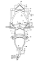
図1において、回転することなく静止せる竪型の筒状をなし主として耐火性レンガで作られた炉体10は、半径方向中央部に落下開口11Aが形成された環板状の炉床11と、該炉床11の外周縁から上方に延びる予熱筒体12と、該炉床11の内周縁、すなわち上記落下開口11Aの周縁から下方に延びる焼成筒体13とを有している。上記炉床11の直上位置には、周方向の複数位置で、半径方向に往復動するプッシャ11Bが設けられている。本実施形態では、プッシャ11Bは上下二本が組として設けられている。
In FIG. 1, a
予熱筒体12は、上記炉床11の外周縁から上方に向け、その上端縁に環板状の天板部12Aが取り付けられている。該天板部12Aは、予熱筒体12の上端縁から半径内方に延び、その内周縁から内筒部12Bが垂下している。この内筒部12Bの下端は炉蓋14の外周部に固定され、該内筒部12Bがこの炉蓋14を、該炉蓋14の外周部に設けられた環状の冷却部14Aを介して支持している。この冷却部14Aは、炉蓋14を支持する強度のダクト状の環体をなしていて、内部へ冷却媒体、例えば冷却水が流通していて、炉蓋14の外周部と内筒部12Bの下端部を冷却して、炉蓋14の支持構造の脆弱化を防止している。
The preheating
炉蓋14には、加熱装置として、燃料と空気を炉体内に噴射供給するバーナ15が、炉蓋14の中央鉛直軸線の位置に設けられている。本発明において、加熱装置としてのバーナ15は、その燃料の種類を問わず、液体燃料でも、気体燃料でも、固体燃料でもよい。あるいは、加熱装置は、炉外で高温化されたガスを炉体内に噴射するようになっていてもよい。
The
上記天板部12A、内筒部12B、予熱筒体12そして炉床11によって包囲される予熱空間は、焼成に先立ち予熱されるべき石灰石等の原料Mを炉床11上に堆積するための空間を形成するのに供され、特に該予熱空間の下部での原料Mの予熱に貢献する。この予熱空間の上部では、原料供給管17が天板部12Aに接続されている。この原料供給管17は、上記天板部12Aの周方向複数位置に設けられており、各原料供給管17は、天板部12Aより上方の炉体外で、二つに分岐されていて、一方が傾斜せる原料投入管17A、他方が上方に垂立する排気管17Bとなっている。複数の原料投入管17Aはそれらの上端で原料貯留槽18の底壁18Aに開口して接続されている。該原料貯留槽18は、仕切板18Bによって上空間と下空間に仕切られており、両空間は仕切板18Bから垂下する短筒18Cにより連通している。また、原料貯留槽18の蓋板には、開閉可能な充填口18Dが設けられている。該充填口18Dは、開口されて適宜時に原料Mを外部から槽内の上空間へ充填されるのに供する。上空間に供給された原料Mは上記短筒18Cを経て下空間に落下する。
The preheating space surrounded by the
上記原料投入管17Aから上方に向け分岐された複数の排気管17Bは、該排気管17Bの上端で、上記原料貯留槽18を取り囲むように設けられた環状ダクト19に接続されており、該環状ダクト19は、その吸引口19Aを経てブロワ等の図示せぬ吸引装置に接続されている。
A plurality of exhaust pipes 17B branched upward from the raw
炉床11の落下開口11Aの周縁から垂下して設けられている筒状に耐熱材料で作られている焼成筒体13は、上部で下方に向け拡径された後に下方に向け円筒状に形成され、その下部には冷却筒体13Bが下方に向けつぼまる形をなして設けられている。上記焼成筒体13の内面には、上下方向での中間位置に、周方向の複数箇所でアーチ状のブリッジ13Aが設けられている。これらのブリッジ13Aは炉体10と同様に耐火レンガで作られていて、上方から見たときに、焼成筒体13の内面位置からその中心軸線位置に向け延び、互いのブリッジ13Aが該中心軸線位置で連結されている。換言すれば、複数のブリッジ13Aは、この中心軸線位置から放射状に半径外方に延びて上記焼成筒体13の内面にまで達している。
A fired
上記焼成筒体13には、周方向で少なくとも上記ブリッジ13Aの位置で、かつ高さ方向で該ブリッジ13Aの直下となる位置に、周壁に半径外方へ没した副加熱空間16が形成されている。この副加熱空間16は周方向に連続する環状をなしていてもよい。該副加熱空間16には、外壁に取り付けられた副加熱装置20が設けられていて、加熱ガスとして、微粉炭素の燃料と空気とが上記副加熱空間16へ噴射するようになっている。上記ブリッジ13Aの上方には、外壁に温度センサ21が設けられていて、上記ブリッジ13Aより上方における原料の温度を検出して、その検出温度に応じて、上記副加熱装置20の噴射燃料と空気の量を調整できるようになっている。
The
上記焼成筒体13の下部からは、下方に向け縮径してテーパ状をなす冷却筒体13Bが垂下し、この冷却筒体13Bからは筒状の排出筒22が垂下している。該排出筒22は、下部が小径となっていて、そこからは、傾斜する取出管23が下方に延びている。該取出管23内には、上下で異なる三位置に、回動式のダンパ23A,23B,23Cが設けられていて、上下のダンパ23A,23Cと中間のダンパ23Bとが開閉時期を異にしている。
From the lower part of the
上記冷却筒体13Bから排出筒22へ移行する範囲には、外部から冷却空気を受ける受気管24が進入して設けられている。該受気管24はL字状に屈曲されて上方に延び、その上端に二段傘状の分気体25が取り付けられている。この傘状の分気体25により、上記受気管24の上端開口へ原料が進入せず、冷却空気が上記上端開口から周囲へ分散送気されるようになる。上記受気管24の垂立部にはその外面に段状の滑落案内体26が取り付けられている。この滑落案内体26は、上面に環状段部が形成されていて、上段に比し下段が大きい直径を有している。好ましくは、この滑落案内体26は、外部から駆動力を受けて、上記受気管24まわりにゆっくりと回転する。焼成後冷却された原料は、上記滑落案内体26の上面を順次滑落して排出筒22の下部へ達する。
An intake pipe 24 that receives cooling air from the outside is provided in a range where the
次に、かかる構成の本実施形態装置について、原料が炉体内へ投入され炉体内で焼成される原理を説明する。 Next, with respect to the apparatus of this embodiment having such a configuration, the principle that raw materials are charged into the furnace and fired in the furnace will be described.
(1)充填口18Dから原料貯留槽18の上空間へ供給された石灰石等の焼成対象物たる原料Mは仕切板18B上に貯留され、複数の短筒18Cから該原料貯留槽18の下空間へ落下し、底壁18Aから斜め下方に延びる複数の原料投入管17Aを経て落下し炉体10内の炉床11上に堆積される。炉床11上での原料Mの堆積層は、炉体10の半径方向内方に安息角をもって自由表面を形成する。
(1) The raw material M which is a firing object such as limestone supplied from the filling
(2)炉蓋14に設けられた加熱装置としての複数のバーナ15からは燃料と空気が噴射されて燃料が燃焼してその火炎が下方に向け噴出される。
(2) Fuel and air are injected from a plurality of
(3)上記炉床11上で堆積層をなす原料Mはその自由表面で上記火炎により加熱されて予熱され、プッシャ11Bの作動により、逐次落下開口11Aから焼成筒体13内へ落下する。予熱された原料Mは落下開口11Aから落下すると、周方向の複数位置に障壁部として設けられたブリッジ13A同士間を通り、さらに落下して、上記焼成筒体13内で、ブリッジ13Aよりも上方位置に自由表面をもつように堆積される。上記ブリッジ13Aの直下には、原料不存在の空間が形成される。すなわち、その空間には原料の堆積層の自由表面が存在するようになる。該空間には副加熱装置20からの燃焼ガスが噴射されており、堆積層はこの空間に面する上記自由表面で加熱されて熱が補給され焼成が促進される。
(3) The raw material M forming a deposition layer on the hearth 11 is heated by the flame on its free surface and preheated, and is sequentially dropped into the
(4)一方、受気管24から取り入れられた外部空気は、該受気管24を経て、冷却空気として、分気体25から堆積層内へ進入し、焼成が十分に進行した原料を冷却しながら、自らは昇温して、予熱空間へ達し、燃焼空気の一部として燃焼に寄与する。
(4) On the other hand, the external air taken in from the air receiving tube 24 enters the deposition layer from the
(5)炉床11上の原料Mの堆積層にはその自由表面から予熱空間での燃焼ガスの一部が層内に流入し、予熱に寄与する。炉外に設けられた環状ダクト19は、図示しない外部のブロワにより吸引されているので、上記炉床11上の原料Mの堆積層を透過する燃焼ガスの一部は、原料Mとの熱交換により降温した後に、上記複数の排気管17B中を上昇し、上記環状ダクト19を経て排気される。
(5) A part of the combustion gas in the preheating space flows from the free surface into the deposition layer of the raw material M on the hearth 11 and contributes to preheating. Since the
(6)このようにして焼成そして冷却された原料Mは排出筒22を降下しつつ冷却され、取出管23を滑落して、交互に開くダンパ23A,23Cそして23Bを経て、製品として取り出される。
(6) The raw material M thus baked and cooled is cooled while descending the
本発明は、図示されそして説明された形態のみには限定されず、種々変更が可能である。例えば、加熱装置そして副加熱装置いずれも、燃料を噴射して燃焼ガスを生ずる装置、あるいは、炉外で燃焼した後に炉内に高温ガスとして噴射する装置とすることができる。又、燃料としては、液体燃料、気体燃料そして固体燃料のいずれをも、あるいはそれらの混合を用いることもできる。固体燃料としては、噴射に好適な微粉炭を用いることができる。 The invention is not limited to the form shown and described, but can be variously modified. For example, both the heating device and the sub-heating device can be a device that injects fuel to generate combustion gas, or a device that injects as a high-temperature gas into the furnace after burning outside the furnace. As the fuel, any of liquid fuel, gaseous fuel, and solid fuel, or a mixture thereof can be used. As the solid fuel, pulverized coal suitable for injection can be used.
さらには、複数の障壁部は、既述のブリッジ部でなくとも、焼成筒体の周壁から半径内方へ突出していて、中心軸線位置で連結されていなくともよい。また、障壁部そして副加熱装置から加熱ガスを受ける空間は、上下方向の複数位置に設けられていてもよく、その場合、上方の障壁部と上下の障壁部とは、周方向で異なる位置に設けられていることが好ましい。 Further, the plurality of barrier portions may not be the above-described bridge portion, but may protrude radially inward from the peripheral wall of the fired cylindrical body, and may not be connected at the central axis position. Further, the space for receiving the heating gas from the barrier portion and the sub-heating device may be provided at a plurality of positions in the vertical direction, in which case the upper barrier portion and the upper and lower barrier portions are at different positions in the circumferential direction. It is preferable to be provided.
また、図示の例では炉床は非回転であったが、本発明は炉床が鉛直中心軸線まわりに回転する形式の竪型炉でも適用できる。 In the illustrated example, the hearth is non-rotating, but the present invention can also be applied to a vertical furnace in which the hearth rotates around the vertical central axis.
10 炉体
11 炉床
11A 落下開口
12 予熱筒体
13 焼成筒体
13A 障壁部(ブリッジ)
14 炉蓋
15 加熱装置(バーナ)
20 副加熱装置
DESCRIPTION OF
14
20 Sub-heating device
Claims (2)
予熱空間は加熱装置が設けられている炉蓋より下方で炉体内面から半径内方に延び中央部に落下開口を有する炉床の外周縁より上方に延びて設けられた予熱筒体の空間内に形成され、焼成空間が該炉床の落下開口の周縁より下方に延びる焼成筒体の空間内に形成され、
上記炉蓋に、上記予熱空間へ向け燃焼ガスもしくは高温ガスを噴射する加熱装置が設けられ、
上記焼成筒体は、高さ方向中間位置で、該焼成筒体の内面から半径内方に延びる障壁部が周方向の複数位置に設けられていると共に、焼成筒体の周壁に、上記障壁部直下に生ずる空間へ燃焼ガスもしくは高温ガスを噴射する副加熱装置が設けられていることを特徴とする竪型焼成炉。 In a vertical firing furnace comprising a vertical cylindrical furnace body having a preheating cylinder forming a preheating space above the hearth and a firing cylinder forming a firing space below the hearth,
The preheating space is within the space of the preheating cylinder provided below the furnace lid where the heating device is provided and extending radially inward from the inner surface of the furnace body and above the outer peripheral edge of the hearth having a drop opening at the center. Formed in the space of the firing cylinder extending downward from the periphery of the drop opening of the hearth,
The furnace cover is provided with a heating device for injecting combustion gas or high-temperature gas toward the preheating space,
The fired cylindrical body is provided with barrier portions extending radially inward from the inner surface of the fired cylindrical body at a plurality of positions in the circumferential direction at an intermediate position in the height direction, and the barrier portion is formed on the peripheral wall of the fired cylindrical body. A vertical firing furnace characterized in that a sub-heating device for injecting combustion gas or high-temperature gas into a space formed immediately below is provided.
Priority Applications (1)
| Application Number | Priority Date | Filing Date | Title |
|---|---|---|---|
| JP2011072431A JP5647054B2 (en) | 2011-03-29 | 2011-03-29 | Vertical firing furnace |
Applications Claiming Priority (1)
| Application Number | Priority Date | Filing Date | Title |
|---|---|---|---|
| JP2011072431A JP5647054B2 (en) | 2011-03-29 | 2011-03-29 | Vertical firing furnace |
Publications (2)
| Publication Number | Publication Date |
|---|---|
| JP2012207828A true JP2012207828A (en) | 2012-10-25 |
| JP5647054B2 JP5647054B2 (en) | 2014-12-24 |
Family
ID=47187724
Family Applications (1)
| Application Number | Title | Priority Date | Filing Date |
|---|---|---|---|
| JP2011072431A Active JP5647054B2 (en) | 2011-03-29 | 2011-03-29 | Vertical firing furnace |
Country Status (1)
| Country | Link |
|---|---|
| JP (1) | JP5647054B2 (en) |
Cited By (1)
| Publication number | Priority date | Publication date | Assignee | Title |
|---|---|---|---|---|
| JP2015197284A (en) * | 2014-04-03 | 2015-11-09 | 大阪瓦斯株式会社 | combustion device for heating furnace |
Citations (4)
| Publication number | Priority date | Publication date | Assignee | Title |
|---|---|---|---|---|
| JPS60129585A (en) * | 1983-12-16 | 1985-07-10 | 宇部興産株式会社 | Double inclined furnace |
| JPH04149046A (en) * | 1990-10-09 | 1992-05-22 | Chisaki:Kk | Method and device for calcining particulate solid |
| JP2000304450A (en) * | 1999-04-16 | 2000-11-02 | Chisaki:Kk | Raw material heating device |
| JP2009068821A (en) * | 2007-08-20 | 2009-04-02 | Chisaki:Kk | Vertical firing furnace |
-
2011
- 2011-03-29 JP JP2011072431A patent/JP5647054B2/en active Active
Patent Citations (4)
| Publication number | Priority date | Publication date | Assignee | Title |
|---|---|---|---|---|
| JPS60129585A (en) * | 1983-12-16 | 1985-07-10 | 宇部興産株式会社 | Double inclined furnace |
| JPH04149046A (en) * | 1990-10-09 | 1992-05-22 | Chisaki:Kk | Method and device for calcining particulate solid |
| JP2000304450A (en) * | 1999-04-16 | 2000-11-02 | Chisaki:Kk | Raw material heating device |
| JP2009068821A (en) * | 2007-08-20 | 2009-04-02 | Chisaki:Kk | Vertical firing furnace |
Cited By (1)
| Publication number | Priority date | Publication date | Assignee | Title |
|---|---|---|---|---|
| JP2015197284A (en) * | 2014-04-03 | 2015-11-09 | 大阪瓦斯株式会社 | combustion device for heating furnace |
Also Published As
| Publication number | Publication date |
|---|---|
| JP5647054B2 (en) | 2014-12-24 |
Similar Documents
| Publication | Publication Date | Title |
|---|---|---|
| CN108368999B (en) | Top combustion furnace | |
| KR101587377B1 (en) | Reverse combustion firewood stove | |
| RU2619434C1 (en) | Installation for solid fuel combustion | |
| JP5184026B2 (en) | Vertical firing furnace | |
| KR101135304B1 (en) | Ladle preheating apparatus | |
| CN102288022B (en) | Sleeve-type gas-burning shaft kiln | |
| JP5647054B2 (en) | Vertical firing furnace | |
| JP2017501309A5 (en) | ||
| JP5628000B2 (en) | Vertical furnace brick support structure | |
| JP5037900B2 (en) | Vertical firing furnace | |
| CN109520302B (en) | Sintering furnace | |
| JP5436784B2 (en) | Vertical firing furnace | |
| JP5065108B2 (en) | heating furnace | |
| JP2013190148A (en) | Vertical kiln | |
| JP2010032148A (en) | Vertical kiln | |
| JP2012112548A (en) | Brick cooling structure of shaft furnace | |
| CN104446020B (en) | A kind of use stove to block combustion system uninterruptedly to add the smokeless lime burner furnace of comburant | |
| US397642A (en) | Fanny e | |
| JP2013148258A (en) | Vertical kiln | |
| JP2014035177A (en) | Vertical kiln | |
| US535115A (en) | Matthew robert moore | |
| US104219A (en) | Improved metallttrqic furnace for iron and steel | |
| US1329470A (en) | Furnace-setting | |
| KR101948989B1 (en) | Solid Fuel Combustion Device | |
| US318496A (en) | Coke-oven |
Legal Events
| Date | Code | Title | Description |
|---|---|---|---|
| A621 | Written request for application examination |
Free format text: JAPANESE INTERMEDIATE CODE: A621 Effective date: 20131017 |
|
| A977 | Report on retrieval |
Free format text: JAPANESE INTERMEDIATE CODE: A971007 Effective date: 20141022 |
|
| TRDD | Decision of grant or rejection written | ||
| A01 | Written decision to grant a patent or to grant a registration (utility model) |
Free format text: JAPANESE INTERMEDIATE CODE: A01 Effective date: 20141029 |
|
| A61 | First payment of annual fees (during grant procedure) |
Free format text: JAPANESE INTERMEDIATE CODE: A61 Effective date: 20141106 |
|
| R150 | Certificate of patent or registration of utility model |
Ref document number: 5647054 Country of ref document: JP Free format text: JAPANESE INTERMEDIATE CODE: R150 |
|
| S531 | Written request for registration of change of domicile |
Free format text: JAPANESE INTERMEDIATE CODE: R313531 |
|
| R350 | Written notification of registration of transfer |
Free format text: JAPANESE INTERMEDIATE CODE: R350 |
|
| R250 | Receipt of annual fees |
Free format text: JAPANESE INTERMEDIATE CODE: R250 |
|
| R250 | Receipt of annual fees |
Free format text: JAPANESE INTERMEDIATE CODE: R250 |
|
| R250 | Receipt of annual fees |
Free format text: JAPANESE INTERMEDIATE CODE: R250 |
|
| R250 | Receipt of annual fees |
Free format text: JAPANESE INTERMEDIATE CODE: R250 |
|
| RD02 | Notification of acceptance of power of attorney |
Free format text: JAPANESE INTERMEDIATE CODE: R3D02 |
|
| R250 | Receipt of annual fees |
Free format text: JAPANESE INTERMEDIATE CODE: R250 |
|
| R250 | Receipt of annual fees |
Free format text: JAPANESE INTERMEDIATE CODE: R250 |
|
| R250 | Receipt of annual fees |
Free format text: JAPANESE INTERMEDIATE CODE: R250 |
|
| R250 | Receipt of annual fees |
Free format text: JAPANESE INTERMEDIATE CODE: R250 |
|
| R250 | Receipt of annual fees |
Free format text: JAPANESE INTERMEDIATE CODE: R250 |
|
| R250 | Receipt of annual fees |
Free format text: JAPANESE INTERMEDIATE CODE: R250 |