JP2012209070A - Fuel cell device - Google Patents
Fuel cell device Download PDFInfo
- Publication number
- JP2012209070A JP2012209070A JP2011072737A JP2011072737A JP2012209070A JP 2012209070 A JP2012209070 A JP 2012209070A JP 2011072737 A JP2011072737 A JP 2011072737A JP 2011072737 A JP2011072737 A JP 2011072737A JP 2012209070 A JP2012209070 A JP 2012209070A
- Authority
- JP
- Japan
- Prior art keywords
- power generation
- temperature
- generation cell
- cell
- abnormal
- Prior art date
- Legal status (The legal status is an assumption and is not a legal conclusion. Google has not performed a legal analysis and makes no representation as to the accuracy of the status listed.)
- Pending
Links
- 239000000446 fuel Substances 0.000 title claims abstract description 112
- 238000010248 power generation Methods 0.000 claims abstract description 261
- 238000001514 detection method Methods 0.000 claims abstract description 25
- 230000002159 abnormal effect Effects 0.000 claims description 70
- 238000000034 method Methods 0.000 claims description 36
- 239000012528 membrane Substances 0.000 abstract description 37
- 239000005518 polymer electrolyte Substances 0.000 abstract description 37
- 239000007787 solid Substances 0.000 abstract description 27
- 238000005516 engineering process Methods 0.000 abstract 1
- 210000004027 cell Anatomy 0.000 description 231
- 239000007800 oxidant agent Substances 0.000 description 21
- 230000001590 oxidative effect Effects 0.000 description 20
- XLYOFNOQVPJJNP-UHFFFAOYSA-N water Substances O XLYOFNOQVPJJNP-UHFFFAOYSA-N 0.000 description 18
- OKKJLVBELUTLKV-UHFFFAOYSA-N Methanol Chemical compound OC OKKJLVBELUTLKV-UHFFFAOYSA-N 0.000 description 6
- 238000010586 diagram Methods 0.000 description 4
- QVGXLLKOCUKJST-UHFFFAOYSA-N atomic oxygen Chemical compound [O] QVGXLLKOCUKJST-UHFFFAOYSA-N 0.000 description 3
- 238000001035 drying Methods 0.000 description 3
- 239000001301 oxygen Substances 0.000 description 3
- 229910052760 oxygen Inorganic materials 0.000 description 3
- UFHFLCQGNIYNRP-UHFFFAOYSA-N Hydrogen Chemical compound [H][H] UFHFLCQGNIYNRP-UHFFFAOYSA-N 0.000 description 2
- 238000006243 chemical reaction Methods 0.000 description 2
- 230000008878 coupling Effects 0.000 description 2
- 238000010168 coupling process Methods 0.000 description 2
- 238000005859 coupling reaction Methods 0.000 description 2
- 230000000694 effects Effects 0.000 description 2
- 239000001257 hydrogen Substances 0.000 description 2
- 229910052739 hydrogen Inorganic materials 0.000 description 2
- 230000005540 biological transmission Effects 0.000 description 1
- 230000015556 catabolic process Effects 0.000 description 1
- 230000007423 decrease Effects 0.000 description 1
- 238000006731 degradation reaction Methods 0.000 description 1
- 230000006866 deterioration Effects 0.000 description 1
- 238000009792 diffusion process Methods 0.000 description 1
- 230000005611 electricity Effects 0.000 description 1
- 239000003792 electrolyte Substances 0.000 description 1
- 230000000284 resting effect Effects 0.000 description 1
- 239000004065 semiconductor Substances 0.000 description 1
Images

Classifications
-
- Y—GENERAL TAGGING OF NEW TECHNOLOGICAL DEVELOPMENTS; GENERAL TAGGING OF CROSS-SECTIONAL TECHNOLOGIES SPANNING OVER SEVERAL SECTIONS OF THE IPC; TECHNICAL SUBJECTS COVERED BY FORMER USPC CROSS-REFERENCE ART COLLECTIONS [XRACs] AND DIGESTS
- Y02—TECHNOLOGIES OR APPLICATIONS FOR MITIGATION OR ADAPTATION AGAINST CLIMATE CHANGE
- Y02E—REDUCTION OF GREENHOUSE GAS [GHG] EMISSIONS, RELATED TO ENERGY GENERATION, TRANSMISSION OR DISTRIBUTION
- Y02E60/00—Enabling technologies; Technologies with a potential or indirect contribution to GHG emissions mitigation
- Y02E60/30—Hydrogen technology
- Y02E60/50—Fuel cells
Landscapes
- Fuel Cell (AREA)
Abstract
Description
本発明は燃料電池装置に関し、特に複数の発電セルが電気的に独立しており、かかる複数の発電セルを直列乃至並列等、任意に接続して用いる場合に適用して有用なものである。 The present invention relates to a fuel cell device, and is particularly useful when applied to a case where a plurality of power generation cells are electrically independent, and the plurality of power generation cells are arbitrarily connected in series or parallel.
近年、燃料に対する高効率な発電手段として、燃料電池が注目されている。燃料電池は、固体高分子電解質膜と、固体高分子電解質膜を挟持する酸化剤極と燃料極と有する発電部を備える発電セルを複数直列接合した発電スタックである場合が一般的である。発電方法は、燃料極に供給される燃料が燃料極上でプロトンと電子とに変わる。電子は電力として取り出される。プロトンは、固体高分子電解質膜中を移動して酸化剤極側へと運搬され、酸化剤極に供給される酸化剤と反応し、水分子を生成する。この水分子は、固体高分子電解質膜中のプロトンの移動に必要である。また、この発電に関する反応は、発熱反応であるため、発電部では熱が発生する。 In recent years, fuel cells have attracted attention as highly efficient power generation means for fuel. In general, a fuel cell is a power generation stack in which a plurality of power generation cells including a solid polymer electrolyte membrane, a power generation unit including a fuel electrode and an oxidant electrode sandwiching the solid polymer electrolyte membrane are connected in series. In the power generation method, the fuel supplied to the fuel electrode changes into protons and electrons on the fuel electrode. Electrons are extracted as electric power. The proton moves through the solid polymer electrolyte membrane and is transported to the oxidant electrode side, reacts with the oxidant supplied to the oxidant electrode, and generates water molecules. This water molecule is necessary for the movement of protons in the solid polymer electrolyte membrane. Further, since the reaction related to power generation is an exothermic reaction, heat is generated in the power generation unit.
しかしながら、燃料電池に接続した負荷の要求電力が小さい場合などは、燃料電池の発電量が小さくなり、各発電セルにおける発電量も低くなり、各発電セルの発電部の温度が低くなる。このとき、積層された複数の発電セルにおいて、内側の発電セルに対し端側の発電セルの温度は発電部外部の温度に影響を受けるため、特に温度が低くなる。そのため端側の発電セルでは、酸化剤極あるいは燃料極で発生した水分子が凝集して水となり、発電部を覆ってしまう。この水により、発電部と燃料あるいは酸化剤と接触を疎外し、発電効率が落ちる。この結果、積層された複数の発電セルの間で、発電が行えないものや、反対に過度な発電を行う必要があるものが出てきてしまい、積層された複数の発電セルの間で発電効率にバラつきが生じ、両者において固体高分子電解質膜の劣化を引き起こすという問題がある。 However, when the required power of the load connected to the fuel cell is small, the power generation amount of the fuel cell is small, the power generation amount in each power generation cell is also low, and the temperature of the power generation unit of each power generation cell is low. At this time, in the plurality of stacked power generation cells, the temperature of the power generation cell on the end side with respect to the inner power generation cell is affected by the temperature outside the power generation unit, and thus the temperature is particularly low. Therefore, in the power generation cell on the end side, water molecules generated at the oxidant electrode or the fuel electrode aggregate to form water, covering the power generation unit. This water alienates the contact between the power generation unit and the fuel or oxidant, and decreases the power generation efficiency. As a result, some of the stacked power generation cells cannot generate power, and some of them need to generate excessive power. On the other hand, power generation efficiency is increased between the stacked power generation cells. There is a problem in that the solid polymer electrolyte membrane deteriorates in both cases.
一方、燃料電池に接続した負荷の要求電力が大きい場合などは、燃料電池の発電量が多きくなり、各発電セルにおける発電量も高くなり、各発電セルの発電部の温度が高くなる。このとき、積層された複数の発電セルにおいて、端側の発電セルに対し内側の発電セルの温度は発電部外部の温度に影響を受けないため、特に温度が高くなる。そのため内側の発電セルでは、酸化剤極あるいは燃料極で発生した水分子が蒸発してしまう。固体高分子電解質膜中の水分子が減ることから、固体高分子電解質膜中のプロトンの伝導性が低下し、固体高分子電解質膜の劣化を引き起こすという問題がある。 On the other hand, when the required power of the load connected to the fuel cell is large, the power generation amount of the fuel cell increases, the power generation amount in each power generation cell also increases, and the temperature of the power generation unit of each power generation cell increases. At this time, in the plurality of stacked power generation cells, the temperature of the power generation cell on the inner side with respect to the power generation cell on the end side is not affected by the temperature outside the power generation unit, and thus the temperature is particularly high. Therefore, in the inner power generation cell, water molecules generated at the oxidant electrode or the fuel electrode are evaporated. Since water molecules in the solid polymer electrolyte membrane are reduced, there is a problem in that the proton conductivity in the solid polymer electrolyte membrane is lowered, causing deterioration of the solid polymer electrolyte membrane.
このように、燃料電池の発電状態により、積層された複数の発電セルの間で、発電が行えないものや、反対に過度な発電を行う必要があるものが出てきてしまい、両者において固体高分子電解質膜の劣化を引き起こす。 In this way, depending on the power generation state of the fuel cell, there are some cells that cannot generate power among the plurality of stacked power generation cells, and on the contrary, those that need to generate excessive power. Causes degradation of the molecular electrolyte membrane.
以上の問題を鑑み、特許文献1では、燃料電池スタックのセル面内の温度分布を制御して、固体高分子電解質膜の過度の濡れまたは渇きを防止する発明が開示されている。燃料電池システムは、燃料電池スタックの温度が低くなり、高分子電解質膜に水が過度に凝集する場合、タンク内の媒体を加温して媒体ポンプで系内へ送り、高分子電解質膜上の水を蒸発させる。また、燃料電池スタックの温度が低くなり、高分子電解質膜が過度に乾いている場合、タンク内の媒体を冷却して媒体ポンプで系内へ送り、高分子電解質膜の温度を下げる。 In view of the above problems, Patent Document 1 discloses an invention in which the temperature distribution in the cell surface of the fuel cell stack is controlled to prevent the solid polymer electrolyte membrane from being excessively wet or thirsty. In the fuel cell system, when the temperature of the fuel cell stack becomes low and the water is excessively aggregated in the polymer electrolyte membrane, the medium in the tank is heated and sent to the system by a medium pump. Evaporate the water. In addition, when the temperature of the fuel cell stack becomes low and the polymer electrolyte membrane is excessively dry, the medium in the tank is cooled and sent to the system by a medium pump to lower the temperature of the polymer electrolyte membrane.
このように、燃料電池スタックの高分子電解質膜の温度を適温に保つことで、高分子電解質膜上の水分子を適度に保ち、発電を安定させるものである。 In this way, by keeping the temperature of the polymer electrolyte membrane of the fuel cell stack at an appropriate temperature, water molecules on the polymer electrolyte membrane are kept moderate and power generation is stabilized.
しかしながら、上記従来技術に係る燃料電池システムは、燃料電池スタックに供給するための媒体や媒体を貯蔵する媒体タンク、また媒体を送る媒体ポンプ等が必要であり、燃料電池スタックの各セルに対して温度制御を行う場合には、さらに媒体ポンプと各セルを接続し媒体を送るための各流路、各流路の媒体の流通を制御するための弁、媒体が所望のセルにのみ接触するための隔壁等の構成が必要であり、システムが大型化し、装置の重量が増大するという問題を発生する。 However, the fuel cell system according to the prior art requires a medium for supplying the fuel cell stack, a medium tank for storing the medium, a medium pump for sending the medium, and the like. For each cell of the fuel cell stack, When temperature control is performed, each medium flow path for connecting the medium pump and each cell to send the medium, a valve for controlling the flow of the medium in each flow path, and the medium contact only with a desired cell Therefore, there is a problem in that the size of the system increases and the weight of the apparatus increases.
本発明は、上記従来技術に鑑み、複数の発電セルから成る発電スタックに対して、所定の温度領域外の温度を有する発電セルを異常温度発電セルとして特定し、異常温度発電セルの接続を制御することで各発電セル同士の温度のバラつきを低減し、固体高分子電解質膜の保護が行える小型な燃料電池装置を提供することを目的とする。 In view of the above prior art, the present invention specifies a power generation cell having a temperature outside a predetermined temperature range as an abnormal temperature power generation cell for a power generation stack composed of a plurality of power generation cells, and controls connection of the abnormal temperature power generation cell. Thus, an object of the present invention is to provide a small fuel cell device capable of reducing the temperature variation between the power generation cells and protecting the solid polymer electrolyte membrane.
上記課題を解決するための本発明の燃料電池装置の第1の特徴は、電気的に独立した複数の発電セルを有する発電スタックと、発電スタックに接続し、各発電セルの接続経路を変更する切換部と、各発電セルの温度をそれぞれ検出する温度検出部と、温度検出部が検出した温度を表す温度信号に基づき、切換部を制御し、所定の温度領域外の温度を有する発電セルを異常温度発電セルとして特定し、異常温度発電セルの接続を制御する制御部とを有することを要旨とする。
かかる特徴によれば、各発電セルの温度状況に応じて各発電セルの発電を制御することができるため、発電セルの高分子電解質膜の温度を適温に保て、固体高分子電解質膜の保護が行える小型な燃料電池装置を実現することができる。
The first feature of the fuel cell device of the present invention for solving the above problems is a power generation stack having a plurality of electrically independent power generation cells, a power generation stack connected to the power generation stack, and a connection path of each power generation cell being changed. A switching unit, a temperature detection unit that detects the temperature of each power generation cell, and a temperature signal that represents the temperature detected by the temperature detection unit, the switching unit is controlled, and a power generation cell having a temperature outside a predetermined temperature range It is specified as an abnormal temperature power generation cell and has a control unit that controls connection of the abnormal temperature power generation cell.
According to such a feature, since the power generation of each power generation cell can be controlled according to the temperature condition of each power generation cell, the temperature of the polymer electrolyte membrane of the power generation cell is maintained at an appropriate temperature, and the solid polymer electrolyte membrane is protected. It is possible to realize a small fuel cell device capable of performing the above.
また本発明の燃料電池装置の第2の特徴は、第1の特徴の燃料電池装置において、
制御部は、温度検出部が検出する温度が最も低い発電セルを異常温度発電セルとして特定し、異常温度発電セルの出力を休止させるように切換部を介して異常温度発電セルの接続状態を制御する処理を含むことを要旨とする。
かかる特徴によれば、特定の発電セルの発電部が水滴で覆われた状態での発電を防ぐことができ、固体高分子電解質膜の保護が行える燃料電池装置を実現することができる。
A second feature of the fuel cell device of the present invention is the fuel cell device according to the first feature.
The control unit identifies the power generation cell having the lowest temperature detected by the temperature detection unit as the abnormal temperature power generation cell, and controls the connection state of the abnormal temperature power generation cell via the switching unit so as to stop the output of the abnormal temperature power generation cell. It is a summary to include processing to do.
According to such a feature, it is possible to realize a fuel cell device that can prevent power generation in a state where a power generation unit of a specific power generation cell is covered with water droplets and can protect the solid polymer electrolyte membrane.
また本発明の燃料電池装置の第3の特徴は、第1の特徴の燃料電池装置において、制御部は、温度検出部が検出する温度が低い発電セルを異常温度発電セルとして特定し、異常温度発電セルのうち、最も温度が低い異常温度発電セルから順に出力を休止させるように切換部を介して異常温度発電セルの接続状態を制御する処理を含むことを要旨とする。
かかる特徴によれば、特定の発電セルの発電部が水滴で覆われた状態での発電を防ぐことができ、固体高分子電解質膜の保護が行える燃料電池装置を実現することができる。
According to a third feature of the fuel cell device of the present invention, in the fuel cell device of the first feature, the control unit identifies a power generation cell having a low temperature detected by the temperature detection unit as an abnormal temperature power generation cell, The gist is to include a process of controlling the connection state of the abnormal temperature power generation cell via the switching unit so that the output is paused in order from the lowest temperature abnormal temperature power generation cell among the power generation cells.
According to such a feature, it is possible to realize a fuel cell device that can prevent power generation in a state where a power generation unit of a specific power generation cell is covered with water droplets and can protect the solid polymer electrolyte membrane.
また本発明の燃料電池装置の第4の特徴は、第1の特徴の燃料電池装置において、制御部は、温度検出部が検出する温度がある一定値以下の発電セルを異常温度発電セルとして特定し、異常温度発電セルの出力を休止させるように切換部を介して異常温度発電セルの接続状態を制御する処理を含むことを要旨とする。
かかる特徴によれば、特定の発電セルの発電部が水滴で覆われた状態での発電を防ぐことができ、固体高分子電解質膜の保護が行える燃料電池装置を実現することができる。
According to a fourth aspect of the fuel cell apparatus of the present invention, in the fuel cell apparatus according to the first aspect, the control unit identifies a power generation cell whose temperature detected by the temperature detection unit is a certain value or less as an abnormal temperature power generation cell. The present invention includes a process of controlling the connection state of the abnormal temperature power generation cell via the switching unit so as to pause the output of the abnormal temperature power generation cell.
According to such a feature, it is possible to realize a fuel cell device that can prevent power generation in a state where a power generation unit of a specific power generation cell is covered with water droplets and can protect the solid polymer electrolyte membrane.
また本発明の燃料電池装置の第5の特徴は、第1から第4のいずれかの特徴の燃料電池装置において、制御部は、温度検出部が検出する温度が最も高い発電セルを異常温度発電セルとして特定し、異常温度発電セルの出力を休止させるように切換部を介して異常温度発電セルの接続状態を制御する処理を含むことを要旨とする。
かかる特徴によれば、特定の発電セルの発電部が乾燥することを防ぎ、固体高分子電解質膜の保護が行える燃料電池装置を実現することができる。
According to a fifth feature of the fuel cell device of the present invention, in the fuel cell device according to any one of the first to fourth features, the control unit converts the power generation cell detected by the temperature detection unit to an abnormal temperature power generation. The gist is to include a process of specifying the cell and controlling the connection state of the abnormal temperature power generation cell via the switching unit so as to stop the output of the abnormal temperature power generation cell.
According to this feature, it is possible to realize a fuel cell device that can prevent the power generation unit of a specific power generation cell from drying and protect the solid polymer electrolyte membrane.
また本発明の燃料電池装置の第6の特徴は、第1から第4のいずれかの特徴の燃料電池装置において、制御部は、温度検出部が検出する温度が高い発電セルを異常温度発電セルとして特定し、異常温度発電セルのうち、最も温度が高い以上温度セルから順に出力を休止させるように切換部を介して異常温度発電セルの接続状態を制御する処理を含むことを要旨とする。
かかる特徴によれば、特定の発電セルの高分子電解質膜が乾燥することを防ぎ、固体高分子電解質膜の保護が行える燃料電池装置を実現することができる。
According to a sixth aspect of the fuel cell device of the present invention, in the fuel cell device according to any one of the first to fourth features, the control unit converts the power generation cell having a high temperature detected by the temperature detection unit to the abnormal temperature power generation cell. And the processing includes controlling the connection state of the abnormal temperature power generation cell via the switching unit so that the output is suspended in order from the temperature cell having the highest temperature among the abnormal temperature power generation cells.
According to this feature, it is possible to realize a fuel cell device that can prevent the polymer electrolyte membrane of a specific power generation cell from drying and protect the solid polymer electrolyte membrane.
また本発明の燃料電池装置の第7の特徴は、第1から第4のいずれかの特徴の燃料電池装置において、制御部は、温度検出部が検出する温度がある一定値以上の発電セルを異常温度発電セルとして特定し、異常温度発電セルの出力を休止させるように切換部を介して異常温度発電セルの接続状態を制御する処理を含むことを要旨とする。
かかる特徴によれば、特定の発電セルの高分子電解質膜が乾燥することを防ぎ、固体高分子電解質膜の保護が行える燃料電池装置を実現することができる。
According to a seventh feature of the fuel cell device of the present invention, in the fuel cell device according to any one of the first to fourth features, the control unit selects a power generation cell having a temperature detected by the temperature detection unit above a certain value. The gist is to include processing for specifying the abnormal temperature power generation cell and controlling the connection state of the abnormal temperature power generation cell via the switching unit so as to stop the output of the abnormal temperature power generation cell.
According to this feature, it is possible to realize a fuel cell device that can prevent the polymer electrolyte membrane of a specific power generation cell from drying and protect the solid polymer electrolyte membrane.
また本発明の燃料電池装置の第8の特徴は、第1から第7のいずれかの特徴の燃料電池装置において、制御部は、出力を休止している異常温度発電セルを、一定の休止時間後に出力を再開させるように切換部を介して異常温度発電セルの接続状態を制御する処理を含むことを要旨とする。
かかる特徴によれば、出力を休止している発電セルの温度を検出し続けることなく、出力を再開することができる燃料電池装置を実現することができる。
An eighth feature of the fuel cell apparatus according to the present invention is that, in the fuel cell device according to any one of the first to seventh features, the control unit sets the abnormal temperature power generation cell that is halting the output to a certain pause time. The gist is to include a process of controlling the connection state of the abnormal temperature power generation cell via the switching unit so that the output is resumed later.
According to this feature, it is possible to realize a fuel cell device capable of restarting output without continuously detecting the temperature of the power generation cell that has stopped outputting.
また本発明の燃料電池装置の第9の特徴は、第1から第8のいずれかの特徴の燃料電池装置において、制御部は、負荷の消費電力値に応じて、切換部を介して異常温度発電セルの接続状態を制御する処理を含むことを含むことを要旨とする。
かかる特徴によれば、スタックから負荷の消費電力に合わせた電力を供給しつつ、固体高分子電解質膜の保護も行うことができる。
According to a ninth feature of the fuel cell apparatus of the present invention, in the fuel cell device according to any one of the first to eighth features, the control unit operates at an abnormal temperature via the switching unit according to the power consumption value of the load. The gist includes including processing for controlling a connection state of the power generation cells.
According to this feature, the solid polymer electrolyte membrane can be protected while supplying electric power from the stack in accordance with the power consumption of the load.
本発明によれば、複数の発電セルから成る発電スタックに対して、所定の温度領域外の温度を有する発電セルを異常温度発電セルとして特定し、異常温度発電セルの接続を制御することで各発電セル同士の温度のバラつきを低減し、固体高分子電解質膜の保護が行える小型な燃料電池装置を提供することが可能である。 According to the present invention, for a power generation stack composed of a plurality of power generation cells, a power generation cell having a temperature outside a predetermined temperature range is specified as an abnormal temperature power generation cell, and each connection is controlled by controlling the connection of the abnormal temperature power generation cell. It is possible to provide a small fuel cell device capable of reducing the temperature variation between the power generation cells and protecting the solid polymer electrolyte membrane.
以下本発明の実施の形態を図面に基づき説明する。
(実施の形態1)
図1から図3に基づいて、本発明の実施の形態1における燃料電池装置1の実施例を説明する。
Embodiments of the present invention will be described below with reference to the drawings.
(Embodiment 1)
An example of the fuel cell device 1 according to Embodiment 1 of the present invention will be described with reference to FIGS. 1 to 3.
(燃料電池装置の構成)
図1及び図2に基づいて、本発明の燃料電池装置の構成を説明する。
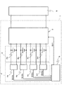
図1には、本発明の実施の形態1に係る燃料電池装置のブロック図を示す。
燃料電池装置1は、水素を燃料とする常温動作型の発電セル2a〜2dを有する発電スタック2と、発電セル2a〜2dの接続を切替える切換部3と、温度検出器4a〜4dを有する温度検出部4と、制御部5を備える。
(Configuration of fuel cell device)
Based on FIG.1 and FIG.2, the structure of the fuel cell apparatus of this invention is demonstrated.
FIG. 1 shows a block diagram of a fuel cell device according to Embodiment 1 of the present invention.
The fuel cell device 1 includes a
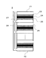
図2には、発電スタック2の詳細図を示す。発電セル2a〜2dは、それぞれ固体高分子電解質膜21の両面に、酸化剤が供給される酸化剤極22と燃料3が供給される燃料極23を有する。ここでは、酸化剤として大気中の空気を利用し、燃料は発電スタック2の外部から供給される例を示す。酸化剤極22側の空間が空気開放されており、大気を酸化剤極側の空間に取り入れる。また、燃料3は、供給部により外部から燃料極側の空間に取り入れられる。
FIG. 2 shows a detailed view of the
燃料は、燃料極上でプロトンと電子とに変わる。発生したプロトンは固体高分子電解質膜11中を移動して酸化剤極22側へと運搬され、酸化剤極で大気中の空気に含まれる酸素と反応し、水を生成する。また電子は図1に示した切換部3を含む回路を通して負荷8へと移動し、負荷3の先には酸化剤極と接続される。各発電セル2a〜2dは燃料供給装置(図示せず)からの燃料の供給によってそれぞれ発電するとともに、発電セル2a〜2d毎にそれぞれ電気的に独立させて構成してある。ここで、「電気的に独立させて構成」とは、各発電セル2a〜2dが直接的には相互に接続されることなく、必ず切換部3を介して接続されるような状態となっていることをいう。
The fuel changes into protons and electrons on the fuel electrode. The generated proton moves through the solid
切換部3は、図示しない複数の切換素子で構成され、各切替素子のON/OFFを切替える事で、所望の発電セル2a〜2dが直列接続あるいは並列接続となる。なお、切換素子は、電力損失の少ないMOSFETなどの半導体素子を用いるのが好ましい。
The switching unit 3 includes a plurality of switching elements (not shown), and desired
温度検出部4が有する温度検出器4a〜4dは、それぞれ発電セル2a〜2dに接続しており、各セルの温度を検出する。
The
制御部5は、温度検出部4の温度検出器4a〜4dから送信される、発電セル2a〜2dの温度信号S02a〜S02dに基づき、切換部3に各発電セル2a〜2dの接続状態を制御する制御信号S01を送信する。制御器5は、マイクロコンピュータ(マイコン)で構成している。マイコンには、温度検出器4a〜4dからの温度信号S02a〜S02dを取り込んで、切換部3に各発電セル2a〜2dの接続状態を制御する制御信号S01を送信するためのプログラムが書き込んである。
The control unit 5 controls the switching unit 3 to connect the
(燃料電池装置の動作)
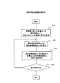
図3は図1に示す燃料電池装置1の制御器5における制御手順を示すフローチャートである。本形態は、制御部5が、発電セル2a〜2dの温度状態に応じて切換部3を制御し、発電セル〜2dの発電状態を変化させるものである。具体的には次の通りである。
(Operation of fuel cell device)
FIG. 3 is a flowchart showing a control procedure in the controller 5 of the fuel cell apparatus 1 shown in FIG. In the present embodiment, the control unit 5 controls the switching unit 3 according to the temperature state of the
図3に基づいて、本発明の燃料電池装置の動作を説明する。
1) 発電スタック2の発電が開始する。
2) 制御部5は発電セル2a〜2dが直列接続として接続するように切換部3に制御信号を送信し制御する(ステップS2)。ここで、制御部5は発電セル2a〜2dが直列接続として接続するように切換部3を制御するのは、発電セル2a〜2dの一部が並列接続である場合に比べ、発電セルの各発電量のばらつきが小さく、負荷への安定した電力供給ができるためである。
The operation of the fuel cell device of the present invention will be described based on FIG.
1) Power generation of the
2) The control unit 5 transmits a control signal to the switching unit 3 so as to connect the
3) 制御部5は、温度検出部4の温度検出器4a〜4dから送信される、発電セル2a〜2dの温度信号S02a〜S02dに基づき、異常温度の発電セルを直列接続から切り離すかあるいは並列接続とするように、切換部3へ制御信号S01を送信し制御する(ステップS3)。一部の発電セルが高温の異常温度であった場合、直列接続から切り離す処理を行うことで発電を行わない休止状態となり、発電セルの温度を下げることができる。また、他の処理として、複数の高温の異常温度のセルを並列接続とし、並列接続のそれぞれの発電セルに流れる電流を、直列接続の発電セルに比べ小さくして、並列接続の発電セルの発電量を小さくなすることで温度を下げることができる。また、一部の発電セルが低温の異常温度であった場合、発電スタック2全体の発電量が小さく、発電スタック2全体の温度が低いと言える。この場合、ステップS3において、異常温度のセルを直列接続から切り離すことで発電を行わない休止状態とする。再び発電スタック2の発電量が増えると、発電スタック2の温度も上昇するため、休止状態の発電セルが発電を行い、水蒸気を生成したとしても、酸化剤極あるいは燃料極において、水が覆いにくくなる。
3) Based on the temperature signals S02a to S02d of the
4) 制御部5は、温度検出部4の温度検出器4a〜4dから送信される、発電セル2a〜2dの温度信号S02a〜S02dに基づき、切り離された発電セルの温度が異常温度でなくなった場合、再び直列接続として接続するように、切換部3へ制御信号S01を送信し制御する(ステップS4)。終了条件が成立するまで、S3〜S4の動作を繰り返す。終了条件とは、例えば負荷の電力要求がなくなる場合や、発電スタック2の発電が終了することを示す。
4) Based on the temperature signals S02a to S02d of the
S2が終了した後の、S3、S4の動作を具体的に説明する。
温度検出部4の温度検出器4aから制御部5へ送信される、発電セル2aの温度信号S02aに、異常温度を示す信号がある場合、制御部5は、切換部へ制御信号S01を送信し、発電セル2aを直列結合から切り離すよう制御する(ステップS3)。続いて、温度検出器4a〜4dから制御部5へ送信される、発電セル2a〜2dの温度信号S02a〜S02dの中に、異常温度を示す信号がなくなった場合、すなわち発電セル2aが正常温度になった場合、制御部5は、切換部3へ制御信号S01を送信し、発電セル2aを直列接合に戻すよう制御する(ステップS4)。
The operation of S3 and S4 after S2 ends will be specifically described.
When there is a signal indicating an abnormal temperature in the temperature signal S02a of the
温度検出部4の温度検出器4b、4cから制御部5へ送信される、発電セル発電セル2b、2cの温度信号S02b、S02cに、異常温度を示す信号がある場合、制御部5は、切換部3へ制御信号S01を送信し、発電セル2b、2cを直列結合から切り離すか、あるいは発電セル2b、2cを並列接続とするよう制御する(ステップS3)。続いて、温度検出器4a〜4dから制御部5へ送信される、発電セル2a〜2dの温度信号S02a〜S02dの中に、異常温度を示す信号がなくなった場合、すなわち発電セル2b、2cが正常温度になった場合、制御部5は、切換部3へ制御信号S01を送信し、発電セル2b、2cを直列接合に戻るよう制御する(ステップS4)。以上のS3からS4の制御を終了条件が成立するまで繰り返す(ステップ5)。発電スタック2の発電が終了するまで繰り返す。
When the temperature signals S02b and S02c of the power generation cell
ここで、ステップ3における異常温度の発電セルとは、予め制御部5に設定されている温度範囲から逸脱している温度を有する発電セルとしても良い。また、発電セル2a〜2dの中で最も低い温度あるいは最も高い温度を有する発電セル、またはその両方としても良い。また、発電セル2a〜2dの中で最も低い温度あるいは最も高い温度を有する発電セルから順に複数の発電セルとしても良い。また、予め制御部5に設定されている基準温度から遠い温度を有する1あるいは複数の発電セルとしても良い。
Here, the power generation cell having an abnormal temperature in Step 3 may be a power generation cell having a temperature deviating from a temperature range set in the control unit 5 in advance. Moreover, it is good also as a power generation cell which has the lowest temperature among the
また、ステップ4における直列接続経路から切り離された発電セルを直列接続経路に直列に接続するための基準は、発電セルの温度を直接用いても良いし、直列接続から切り離された後に経過した時間を用いても良い。
Moreover, the reference | standard for connecting the power generation cell disconnected from the serial connection path | route in
ここで、発電セルの発電効率や燃料極及び酸化剤極及び固体高分子電解質膜の保護の観点から導く異常温度は、燃料電池装置を運転する環境の外気温や湿度、あるいは風量によっても異なるが、水分子が過度に固体高分子電解質膜や酸化剤極あるいは燃料極発電から蒸発する60度以上、または水分子が過度に固体高分子電解質膜や酸化剤極あるいは燃料極発電40度以下の範囲とすることが望ましい。なお、燃料や大気中の酸素などの酸化剤を加湿して発電セルへ供給する場合は、異常温度範囲を高温側へシフトさせても良い。
なお、発電セル2a〜2dは、燃料極へ供給する燃料としてメタノールを用いるダイレクトメタノール型燃料電池(DMFC)、又はその他の方式の燃料電池であっても良い。また、発電セル2a乃至2dの個数は4個に限るものではなく、必要に応じた個数とすることができる。
Here, the abnormal temperature derived from the viewpoint of the power generation efficiency of the power generation cell and the protection of the fuel electrode, the oxidant electrode, and the solid polymer electrolyte membrane varies depending on the outside temperature, humidity, or air volume of the environment in which the fuel cell device is operated. The water molecules excessively evaporate from the solid polymer electrolyte membrane, the oxidant electrode or the fuel electrode power generation, or the water molecules excessively evaporate from the solid polymer electrolyte membrane, the oxidant electrode or the fuel electrode power generation in a range of 40 degrees or less. Is desirable. In addition, when humidifying oxidizers, such as fuel and atmospheric oxygen, and supplying it to a power generation cell, you may shift an abnormal temperature range to the high temperature side.
The
(燃料電池装置の作用・効果)
各発電セルの温度を適温に保つことで、各発電セル同士の温度のバラつきを低減し、固体高分子電解質膜の保護を行うことができる。
(Operation and effect of fuel cell device)
By maintaining the temperature of each power generation cell at an appropriate temperature, the temperature variation between the power generation cells can be reduced, and the solid polymer electrolyte membrane can be protected.
(実施の形態2)
図4から図5に基づいて、本発明の実施の形態2における燃料電池装置1の実施例を説明する。
(燃料電池装置の構成)
図4には、本発明の実施の形態2に係る燃料電池装置のブロック図を示す。本発明の実施の形態1と共通する構成については、同じ番号を付し、説明は省略する。
(Embodiment 2)
An example of the fuel cell device 1 according to
(Configuration of fuel cell device)
FIG. 4 shows a block diagram of a fuel cell device according to
本発明の実施の形態2が、実施の形態1と異なる点は、制御部5が、負荷8からの負荷消費電力信号S03を送信される点である。制御器5は、マイクロコンピュータ(マイコン)で構成している。マイコンには、温度検出器4a〜4dからの温度信号S02a〜S02dと負荷6の負荷消費電力信号S03を取り込んで、切換部3に各発電セル2a〜2dの接続状態を制御する制御信号S01を送信するためのプログラムが書き込んである。
The second embodiment of the present invention is different from the first embodiment in that the control unit 5 transmits a load power consumption signal S03 from the load 8. The controller 5 is composed of a microcomputer. The microcomputer receives the temperature signals S02a to S02d from the
負荷消費電力信号S03は、負荷8における消費電力を検出することができる出力検出器から送信される。したがって、負荷消費電力を直接検出する電力計も含まれる。 The load power consumption signal S03 is transmitted from an output detector that can detect power consumption in the load 8. Therefore, a wattmeter that directly detects load power consumption is also included.
(燃料電池装置の動作)
図5に基づいて、本発明の燃料電池装置の動作を説明する。
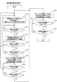
図5は図1に示す燃料電池装置1の制御器5における制御手順を示すフローチャートである。本形態は、本形態は、制御部5が、負荷8の消費電力及び発電セル2a〜2dの温度状態に応じて、切換部3を制御し、発電させる発電セルの個数を変化させるものである。
(Operation of fuel cell device)
The operation of the fuel cell device of the present invention will be described based on FIG.
FIG. 5 is a flowchart showing a control procedure in the controller 5 of the fuel cell apparatus 1 shown in FIG. In the present embodiment, the control unit 5 controls the switching unit 3 in accordance with the power consumption of the load 8 and the temperature state of the
本形態における各発電セル2a乃至2dは、燃料としての水素をアノード(−極)へ、酸素(空気)をカソード(+極)へそれぞれ供給することにより発電する固体高分子形燃料電池(PEFC)で構成している。また、発電セル2a乃至2dは、その出力電圧が0.45[V]のときに最大出力が1.08[W]得られるものを4個用いた。なお、発電セル2a乃至2dの1個当たりの標準動作電圧を0.6Vとし、発電セル2a乃至2dの電圧はこの電圧を動作下限電圧とする。標準電圧は、発電セル2a乃至2dの発電特性において、顕著な拡散過電圧が認められない電圧範囲、PEFCの場合で、およそ0.3乃至0.8Vの間で設定する。このときの発電セル2a乃至2dの1個当たりの標準出力電力は、0.72[W](以下、この出力電力を「P1」と略称する。)である。したがって、4個の発電セル2a乃至2dの出力時には、0.72[W]×4=2.88[W](以下、この出力電力を「P4」と略称する。)の出力が得られ、3個での出力時には、0.72[W]×3=2.16[W](以下、この出力電力を「P3」と略称する。)、2個での出力時には、0.72[W]×2=1.44[W](以下、この出力電力を「P2」と略称する。)の出力が得られる。ここで、本形態では、前記標準出力電力に発電セル2a乃至2dの個数を掛けた出力電力P1,P2,P3,P4が、それぞれ「燃料電池2の発電特性から予め設定した出力電力」ということになる。
Each of the
1) 発電スタック2の発電が開始する。
2) 制御部5は発電セル2a〜2dが直列接続として接続するように切換部3に制御信号S01を送信し制御する(ステップS12)。
3) 制御部5は、負荷8から送信される消費電力信号S03が、負荷電力P3以下を示すものであるか、否かを判定する(ステップS13)。ステップS13の処理でP3以下でなければ、P3以下になるまでステップS13の処理に戻してステップS13の処理を繰り返す。
1) Power generation of the
2) The control unit 5 transmits and controls the control signal S01 to the switching unit 3 so that the
3) The control unit 5 determines whether or not the power consumption signal S03 transmitted from the load 8 indicates the load power P3 or less (step S13). If it is not less than P3 in the process of step S13, it will return to the process of step S13 and will repeat the process of step S13 until it becomes P3 or less.
4) ステップS13の処理で負荷8から送信される消費電力信号S03がP3以下を示すものであれば、発電セル2a〜2dの何れか1個は休止させて良いので、制御部5は、温度検出器4a〜4dからの信号S02a〜S02dに基づき、発電セル2a〜2dのうち異常温度の発電セルの1個を直列接続経路から切り離す信号S01を切換部3に送信する(ステップS14)。
4) If the power consumption signal S03 transmitted from the load 8 in the process of step S13 indicates P3 or less, any one of the
5) 制御器5が演算した負荷8から送信される消費電力信号S03が、P3以下を示すものであるか、否かを判定し、P3以下である場合はステップS12の処理に戻す(ステップS15)。
7) ステップS15の処理で負荷8から送信される消費電力信号S03がP3より高いことを示すものであると判定された場合には、さらに制御器5が演算した負荷8から送信される消費電力信号S03が、P2以下を示すものであるか、否かを判定する(ステップS16)。
5) It is determined whether or not the power consumption signal S03 transmitted from the load 8 calculated by the controller 5 indicates P3 or less, and if it is P3 or less, the process returns to Step S12 (Step S15). ).
7) If it is determined in step S15 that the power consumption signal S03 transmitted from the load 8 is higher than P3, the power consumption transmitted from the load 8 calculated by the controller 5 It is determined whether or not the signal S03 indicates P2 or less (step S16).
6) ステップS16の処理でP2以下でなければ、ステップS15の処理に戻る。
7) ステップS16の処理で負荷8から送信される消費電力信号S03がP2以下を示すものであれば、発電セル2a乃至2dのさらにもう1個は休止させて良いので、制御部5は、温度検出器4a〜4dからの信号S02a〜S02dに基づき、発電セル2a〜2dのうち休止している発電セルを含める異常温度の発電セルの2個を直列接続経路から切り離す信号S01を切換部3に送信する(ステップS17)。
6) If not P2 or less in the process of step S16, the process returns to the process of step S15.
7) If the power consumption signal S03 transmitted from the load 8 in step S16 indicates P2 or less, the other one of the
8) 制御器5が演算した負荷8から送信される消費電力信号S03が、P2以下を示すものであるか、否かを判定し、P2以下である場合はステップS12の処理に戻す(ステップS18)。
9) ステップS18の処理で負荷8から送信される消費電力信号S03がP2より高いことを示すものであると判定された場合には、さらに制御器5が演算した負荷8から送信される消費電力信号S03が、P1以下であるか、否かを判定する(ステップS19)。
8) It is determined whether or not the power consumption signal S03 transmitted from the load 8 calculated by the controller 5 indicates P2 or less. If it is equal to or less than P2, the process returns to Step S12 (Step S18). ).
9) If it is determined in step S18 that the power consumption signal S03 transmitted from the load 8 is higher than P2, the power consumption transmitted from the load 8 further calculated by the controller 5 It is determined whether or not the signal S03 is equal to or less than P1 (step S19).
10) ステップS19の処理でP1以下でなければ、ステップS18の処理に戻る。
11) ステップS19の処理で負荷8から送信される消費電力信号S03がP1以下を示すものであれば、発電セル2a〜2dのうち休止している発電セルを含める異常温度の発電セルの3個を休止させて良いので、制御部5は、温度検出器4a〜4dからの信号S02a〜S02dに基づき、発電セル2aから2dのうち休止している発電セルを含める異常温度の発電セルの3個を直列接続経路から切り離す信号S01を切換部3に送信する(ステップS20)。
10) If not P1 or less in the process of step S19, the process returns to the process of step S18.
11) If the power consumption signal S03 transmitted from the load 8 in the process of step S19 indicates P1 or less, three of the power generation cells having abnormal temperatures including the power generation cells that are idle among the
12) 制御器5が演算した負荷8から送信される消費電力信号S03が、P1以下を示すものであるか、否かを判定し、P1以下である場合はステップS12の処理に戻す(ステップS21)。
13) ステップS21の処理で負荷8から送信される消費電力信号S03がP1より高いことを示すものであると判定された場合には、負荷8から送信される消費電力信号S03が消費電力がゼロを示すものであるか、否かを判定し(ステップS22)、ゼロを示すものになるまでステップS21の処理に戻してステップS21以降の処理を繰り返すとともに、ゼロを示すものになった時点で燃料電池の発電を終了させる。
12) It is determined whether or not the power consumption signal S03 transmitted from the load 8 calculated by the controller 5 indicates P1 or less. If the power consumption signal S03 is P1 or less, the process returns to Step S12 (Step S21). ).
13) If it is determined in step S21 that the power consumption signal S03 transmitted from the load 8 is higher than P1, the power consumption signal S03 transmitted from the load 8 has zero power consumption. (Step S22), the process returns to the process of step S21 until it becomes zero, and the processes in and after step S21 are repeated, and the fuel is displayed when the value indicates zero. Terminate battery power generation.
上記ステップS14、40、45において、異常温度の発電セルを直列接続経路から切り離す動作を行っているが、実施の形態1で記載したように、直列接続経路から並列接続経路へ切り替える動作を行っても良い。
(燃料電池装置の作用・効果)
制御部5が、負荷8の負荷消費電力を得ることで、負荷消費電力に応じて異常温度が検出される発電セルの接続関係を変化させることができるため、各発電セル同士の温度のバラつきを低減し、固体高分子電解質膜の保護を行うことができる。
In steps S14, S40, S45, the operation of disconnecting the abnormal temperature power generation cell from the series connection path is performed, but as described in the first embodiment, the operation of switching from the series connection path to the parallel connection path is performed. Also good.
(Operation and effect of fuel cell device)
Since the control unit 5 obtains the load power consumption of the load 8, the connection relationship of the power generation cells in which the abnormal temperature is detected can be changed according to the load power consumption. And the solid polymer electrolyte membrane can be protected.
1、11 燃料電池装置
2 発電スタック
3 切換部
4 温度検出部
5、15 制御部
6(8) 負荷
21、22 端部
23 酸化剤極
24 高分子電解質膜
25 燃料極
26 酸化剤入口
27 燃料入口
28 燃料供給路
S01 制御信号
S02a〜S02d 温度信号
S03 消費電力信号
DESCRIPTION OF
Claims (9)
前記発電スタックに接続し、各前記発電セルの接続経路を変更する切換部と、
各前記発電セルの温度をそれぞれ検出する温度検出部と、
前記温度検出部が検出した前記温度を表す温度信号に基づき、前記切換部を制御し、所定の温度領域外の前記温度を有する前記発電セルを異常温度発電セルとして特定し、前記異常温度発電セルの接続を制御する制御部とを有することを特徴とする燃料電池装置。 A power generation stack having a plurality of electrically independent power generation cells;
A switching unit that connects to the power generation stack and changes the connection path of each power generation cell;
A temperature detector for detecting the temperature of each of the power generation cells;
Based on a temperature signal representing the temperature detected by the temperature detection unit, the switching unit is controlled, the power generation cell having the temperature outside a predetermined temperature range is specified as an abnormal temperature power generation cell, and the abnormal temperature power generation cell And a control unit for controlling the connection of the fuel cell device.
Priority Applications (1)
| Application Number | Priority Date | Filing Date | Title |
|---|---|---|---|
| JP2011072737A JP2012209070A (en) | 2011-03-29 | 2011-03-29 | Fuel cell device |
Applications Claiming Priority (1)
| Application Number | Priority Date | Filing Date | Title |
|---|---|---|---|
| JP2011072737A JP2012209070A (en) | 2011-03-29 | 2011-03-29 | Fuel cell device |
Publications (1)
| Publication Number | Publication Date |
|---|---|
| JP2012209070A true JP2012209070A (en) | 2012-10-25 |
Family
ID=47188650
Family Applications (1)
| Application Number | Title | Priority Date | Filing Date |
|---|---|---|---|
| JP2011072737A Pending JP2012209070A (en) | 2011-03-29 | 2011-03-29 | Fuel cell device |
Country Status (1)
| Country | Link |
|---|---|
| JP (1) | JP2012209070A (en) |
Cited By (5)
| Publication number | Priority date | Publication date | Assignee | Title |
|---|---|---|---|---|
| JP2015128039A (en) * | 2013-12-27 | 2015-07-09 | エスケー イノベーション カンパニー リミテッドSk Innovation Co., Ltd. | Fuel cell calorific value control device |
| JP2016005297A (en) * | 2014-06-13 | 2016-01-12 | トヨタ自動車株式会社 | Electric vehicle and control method thereof |
| WO2017115952A1 (en) * | 2015-12-30 | 2017-07-06 | 주식회사 효성 | Operation control device and control method of submodule of modular multi-level converter |
| WO2019003942A1 (en) * | 2017-06-29 | 2019-01-03 | 京セラ株式会社 | Power generation apparatus, control apparatus, and control program |
| CN112103584A (en) * | 2019-06-17 | 2020-12-18 | 株式会社牧田 | Battery-powered portable tool |
Citations (7)
| Publication number | Priority date | Publication date | Assignee | Title |
|---|---|---|---|---|
| JP2003151597A (en) * | 2001-11-08 | 2003-05-23 | Nissan Motor Co Ltd | Fuel cell system |
| JP2003178786A (en) * | 2001-12-12 | 2003-06-27 | Matsushita Electric Ind Co Ltd | Power supply and electronic equipment |
| JP2005063712A (en) * | 2003-08-08 | 2005-03-10 | Toyota Motor Corp | Fuel cell system and operation method thereof |
| JP2006114244A (en) * | 2004-10-12 | 2006-04-27 | Nissan Motor Co Ltd | Fuel cell system |
| JP2006114481A (en) * | 2004-09-16 | 2006-04-27 | Seiko Instruments Inc | Fuel cell system |
| JP2008103321A (en) * | 2006-10-17 | 2008-05-01 | Samsung Sdi Co Ltd | FUEL CELL SYSTEM AND METHOD OF OPERATING FUEL CELL SYSTEM |
| JP2008300140A (en) * | 2007-05-30 | 2008-12-11 | Sony Corp | Fuel cell system |
-
2011
- 2011-03-29 JP JP2011072737A patent/JP2012209070A/en active Pending
Patent Citations (7)
| Publication number | Priority date | Publication date | Assignee | Title |
|---|---|---|---|---|
| JP2003151597A (en) * | 2001-11-08 | 2003-05-23 | Nissan Motor Co Ltd | Fuel cell system |
| JP2003178786A (en) * | 2001-12-12 | 2003-06-27 | Matsushita Electric Ind Co Ltd | Power supply and electronic equipment |
| JP2005063712A (en) * | 2003-08-08 | 2005-03-10 | Toyota Motor Corp | Fuel cell system and operation method thereof |
| JP2006114481A (en) * | 2004-09-16 | 2006-04-27 | Seiko Instruments Inc | Fuel cell system |
| JP2006114244A (en) * | 2004-10-12 | 2006-04-27 | Nissan Motor Co Ltd | Fuel cell system |
| JP2008103321A (en) * | 2006-10-17 | 2008-05-01 | Samsung Sdi Co Ltd | FUEL CELL SYSTEM AND METHOD OF OPERATING FUEL CELL SYSTEM |
| JP2008300140A (en) * | 2007-05-30 | 2008-12-11 | Sony Corp | Fuel cell system |
Cited By (9)
| Publication number | Priority date | Publication date | Assignee | Title |
|---|---|---|---|---|
| JP2015128039A (en) * | 2013-12-27 | 2015-07-09 | エスケー イノベーション カンパニー リミテッドSk Innovation Co., Ltd. | Fuel cell calorific value control device |
| JP2016005297A (en) * | 2014-06-13 | 2016-01-12 | トヨタ自動車株式会社 | Electric vehicle and control method thereof |
| WO2017115952A1 (en) * | 2015-12-30 | 2017-07-06 | 주식회사 효성 | Operation control device and control method of submodule of modular multi-level converter |
| KR101774977B1 (en) | 2015-12-30 | 2017-09-05 | 주식회사 효성 | Operation control apparatus and method of redundant sub module in modular multilevel converter |
| WO2019003942A1 (en) * | 2017-06-29 | 2019-01-03 | 京セラ株式会社 | Power generation apparatus, control apparatus, and control program |
| JPWO2019003942A1 (en) * | 2017-06-29 | 2020-04-09 | 京セラ株式会社 | Power generation device, control device, and control program |
| CN112103584A (en) * | 2019-06-17 | 2020-12-18 | 株式会社牧田 | Battery-powered portable tool |
| US11955615B2 (en) | 2019-06-17 | 2024-04-09 | Makita Corporation | Battery-powered portable tool |
| CN112103584B (en) * | 2019-06-17 | 2024-06-04 | 株式会社牧田 | Battery powered portable tool |
Similar Documents
| Publication | Publication Date | Title |
|---|---|---|
| US7141323B2 (en) | Method and apparatus for electrochemical compression and expansion of hydrogen in a fuel cell system | |
| US9099703B2 (en) | Fast MEA break-in and voltage recovery | |
| US9385380B2 (en) | Fuel cell humidification management method and system | |
| CA2826749C (en) | Electrochemical fuel cell assembly | |
| CA2600817C (en) | Air-cooled fuel cell system | |
| CN106992307B (en) | The liquid circulation subsystem of fuel cell pack electricity generation system | |
| JP2012209070A (en) | Fuel cell device | |
| JP2002175821A (en) | Fuel cell system | |
| WO2009113305A1 (en) | Fuel cell system and method of operating the same | |
| KR101287105B1 (en) | Fuel cell system and driving method thereof | |
| JP5423892B2 (en) | Fuel cell system and fuel cell operating method | |
| JP2012160442A (en) | Fuel cell system and method for controlling the same | |
| JP5482108B2 (en) | Fuel cell system and operation method thereof | |
| KR101601060B1 (en) | Fuel cell stack | |
| Riascos et al. | Optimal temperature control in PEM fuel cells | |
| Abd Rahman et al. | Simulation of PEMFC stack for portable power generator application | |
| JP2005032585A (en) | Power supply system using fuel cell | |
| CN100470909C (en) | High temperature fuel cell system with cooling device and method of operating the system | |
| US8383278B2 (en) | Fuel cell system and operating method thereof | |
| KR102541624B1 (en) | Fuel cell system for vehicle and controlling method thereof | |
| Riascos et al. | Controlling operating temperature in PEM fuel cells | |
| JP2017162655A (en) | Fuel cell system | |
| JP2004179042A (en) | Polymer electrolyte fuel cell | |
| KR101558343B1 (en) | fuel cell management method | |
| KR101084078B1 (en) | Fuel cell system and its driving method |
Legal Events
| Date | Code | Title | Description |
|---|---|---|---|
| A621 | Written request for application examination |
Free format text: JAPANESE INTERMEDIATE CODE: A621 Effective date: 20140116 |
|
| A977 | Report on retrieval |
Free format text: JAPANESE INTERMEDIATE CODE: A971007 Effective date: 20141112 |
|
| A131 | Notification of reasons for refusal |
Free format text: JAPANESE INTERMEDIATE CODE: A131 Effective date: 20141125 |
|
| A521 | Written amendment |
Free format text: JAPANESE INTERMEDIATE CODE: A523 Effective date: 20150121 |
|
| A02 | Decision of refusal |
Free format text: JAPANESE INTERMEDIATE CODE: A02 Effective date: 20150414 |