JP2012209227A - Long arc type metal halide lamp and light irradiation device - Google Patents
Long arc type metal halide lamp and light irradiation device Download PDFInfo
- Publication number
- JP2012209227A JP2012209227A JP2011076072A JP2011076072A JP2012209227A JP 2012209227 A JP2012209227 A JP 2012209227A JP 2011076072 A JP2011076072 A JP 2011076072A JP 2011076072 A JP2011076072 A JP 2011076072A JP 2012209227 A JP2012209227 A JP 2012209227A
- Authority
- JP
- Japan
- Prior art keywords
- metal halide
- halide lamp
- arc tube
- lamp
- halogen
- Prior art date
- Legal status (The legal status is an assumption and is not a legal conclusion. Google has not performed a legal analysis and makes no representation as to the accuracy of the status listed.)
- Withdrawn
Links
Images

Landscapes
- Discharge Lamps And Accessories Thereof (AREA)
- Vessels And Coating Films For Discharge Lamps (AREA)
- Discharge Lamp (AREA)
Abstract
【課題】 過冷却状態におかれた場合でも寿命を伸ばすことができ、かつ、始動性が良好なメタルハライドランプ、更にはメタルハライドランプを備えた光照射装置を提供すること。
【解決手段】 ハロゲンが封入されたメタルハライドランプにおいて、ハロゲンは発光管の内容積に対して0.3μmol/cc以上封入され、発光管の外表面上にその管軸に沿うように導電性物質からなる膜が一方と他方の電極間に亘り設けられている。また、前記膜の上にシリカ粒子及び/又はアルミナ粒子よりなる保護層が具備される。光照射装置においては、前記メタルハライドランプと、略樋状の反射ミラーと、冷却機構を具備し、前記反射ミラーは冷却風用の開口を有し、前記メタルハライドランプは前記導電性物質からなる膜が前記反射ミラーの開口に向かって配置されている。
【選択図】 図1PROBLEM TO BE SOLVED: To provide a metal halide lamp which can extend the life even in a supercooled state and has good startability, and further provides a light irradiation device equipped with a metal halide lamp.
In a metal halide lamp in which halogen is encapsulated, the halogen is encapsulated in an amount of 0.3 μmol / cc or more with respect to the inner volume of the arc tube, and from a conductive material along the tube axis on the outer surface of the arc tube. Is formed between one and the other electrode. Further, a protective layer made of silica particles and / or alumina particles is provided on the film. In the light irradiation device, the metal halide lamp, a substantially bowl-shaped reflection mirror, and a cooling mechanism are provided, the reflection mirror has an opening for cooling air, and the metal halide lamp has a film made of the conductive material. It arrange | positions toward the opening of the said reflective mirror.
[Selection] Figure 1
Description
本発明は、ロングアーク型メタルハライドランプおよびこれを用いた光照射装置に関する。 The present invention relates to a long arc type metal halide lamp and a light irradiation apparatus using the same.
液晶ディスプレイパネルの製造工程においてガラス基板を貼り合わせる際、ガラス基板とガラス基板の間に塗布されたシール剤を硬化するための紫外線光源としてメタルハライドランプが好適に利用されている。かかる製造工程においては、棒状のメタルハライドランプとその背面に配置された反射ミラーとを備えた光照射装置が使用される。 When bonding a glass substrate in the manufacturing process of a liquid crystal display panel, a metal halide lamp is suitably used as an ultraviolet light source for curing a sealing agent applied between the glass substrate and the glass substrate. In such a manufacturing process, a light irradiation apparatus including a rod-shaped metal halide lamp and a reflection mirror disposed on the back surface thereof is used.
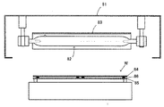
図6にこの装置を示す。ランプハウス81内にロングアーク型のメタルハライドランプ82が配置される。メタルハライドランプ82の上方には反射ミラー83が配置されており、ランプからの放射光はミラー83で反射されることにより下方に設置されたワークWに高効率に照射する。ワークWは上述したようにガラス基板84とガラス基板85の間にシール剤86が塗布されたものである。
このような用途においてはシール剤86の特性に由来して波長300〜400nm域の紫外線照射が要求されており、上記波長帯において良好な光放射が得られる鉄を発光管内部に封入したメタルハライドランプ82が好適に使用されている。
FIG. 6 shows this apparatus. A long arc type
In such an application, ultraviolet irradiation in the wavelength region of 300 to 400 nm is required due to the characteristics of the
近時、上述した液晶ディスプレイパネルの製造工程では、製造時にかかる電力量を低く抑えることを目的として、メタルハライドランプの入力電力をワーク照射時と非照射時との間で切り替え、非照射時の電力を低くするようにして行っている。例えば、1つのワークを処理するため、ワークに対して数十秒間、比較的高い電力でランプを点灯する。照射が終了した後、ワークを移動して次のワークが搬送されてくるまでの間、数十秒間は光の照射を遮断して比較的低い電力に切り替えて点灯するようにしている。
なお、ここでいう「比較的高い電力」とは、例えば定格消費電力に対して50%以上となるような電力であり、「比較的低い電力」とは、比較的高い電力よりも低い電力となるよう設定された電力である。
このような、高い電力と低い電力とを切り替えるいわば擬似的な間欠点灯を行うことで、メタルハライドランプを省電力で駆動することと同時に、ランプをON/OFFして切り替えるよりもランプの始動性を速やかに行い、多数のワークを連続的に処理することを実現している。
Recently, in the manufacturing process of the above-mentioned liquid crystal display panel, the input power of the metal halide lamp is switched between the irradiation time and the non-irradiation time for the purpose of keeping the amount of electric power required at the time of manufacturing low. Is going to be low. For example, in order to process one workpiece, the lamp is turned on with relatively high power for several tens of seconds. After the irradiation is completed, the irradiation of light is interrupted for several tens of seconds until the next workpiece is transferred after the workpiece is moved, and the light is switched to a relatively low power to light up.
The “relatively high power” here is, for example, power that is 50% or more of the rated power consumption, and the “relatively low power” is a power that is lower than a relatively high power. It is the electric power set to become.
By switching between high power and low power, so-called pseudo intermittent lighting, the metal halide lamp can be driven with low power consumption, and at the same time, the startability of the lamp can be improved compared to switching the lamp on and off. Promptly, it is possible to process many workpieces continuously.
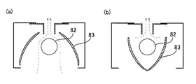
図7は、この光照射装置において、ランプを間欠点灯する際のシャッタの開閉機構を説明する図である。図7(a)はシャッタが開いた状態、(b)はシャッタが閉じた状態である。
同図に示すように樋状のミラーは紙面上側の中心部が分割して構成されており、ここに冷却風の通風口が形成されている。ワークに対して光を照射する期間、ミラーはランプの背後(上部)に位置しており、ワークへの光照射が完遂するとミラーが回動してランプからの放射光を遮光することでシャッタとして機能する。
FIG. 7 is a diagram for explaining a shutter opening / closing mechanism when the lamp is intermittently lit in this light irradiation apparatus. FIG. 7A shows a state where the shutter is open, and FIG. 7B shows a state where the shutter is closed.
As shown in the figure, the bowl-shaped mirror is configured by dividing the central portion on the upper side of the paper, and a ventilation port for cooling air is formed therein. The mirror is positioned behind (upper) the lamp during the period when the workpiece is irradiated with light. When the workpiece is completely irradiated with the light, the mirror rotates to shield the emitted light from the lamp. Function.
メタルハライドランプの冷却は、上述したようにミラー中央部の通風口を介して行われ、発光管の表面温度が例えば800℃程度となるように冷却条件が設定される。しかしながら実際には、光照射装置の個体差や長時間使用したことよる経時変化等に由来して冷却条件がばらつき、過冷却状態が生じることがある。メタルハライドランプが過冷却状態になるとメタルハライドの反応が鈍くなって所期の照度が得られなくなり短寿命になる。このようなランプの照度低下は、予期せず急速に起こるため、光照射装置においてはワークの処理が突然未完となることがあり、上述したような光反応を利用した装置においては極めて重大な問題となっている。 As described above, the cooling of the metal halide lamp is performed through the ventilation opening at the center of the mirror, and the cooling conditions are set so that the surface temperature of the arc tube is about 800 ° C., for example. However, in actuality, the cooling conditions may vary due to individual differences of the light irradiation devices or changes over time due to long-term use, and an overcooled state may occur. When the metal halide lamp is overcooled, the reaction of the metal halide becomes dull and the desired illuminance cannot be obtained, resulting in a short life. Since such a decrease in the illuminance of the lamp occurs unexpectedly and rapidly, the processing of the workpiece may be suddenly incomplete in the light irradiation device, and a very serious problem in the device using the light reaction as described above. It has become.
このようなランプの過冷却に付随して生じる短寿命化の対策として、メタルハライドとハロゲンとの反応が発生し易くなるようハロゲンの封入量を増やすことが検討されている。つまり、従来技術に係るハロゲンの封入量は0.2μmol/cc程度であったが、これを1.5倍の0.3μmol/cc以上、更に好ましくは従来の2倍の0.4μmol/cc程度とすることによって、過冷却状態であってもメタルハライドの反応を促し、所期の照度を得るというものである。
上記技術によれば、先に説明したような電力の切り替えやシャッタの開閉制御に伴う温度変化が生じた場合にも、照度低下に対して一定の効果が得られることが本発明者らの検討で確認された。
ところが、ハロゲン化物の封入量を増大させた場合には、従来使用していた電源装置を用いて点灯しようとすると始動性が悪くなり、あるランプでは全く点灯させることができないといった事象が生じることが判明した。
そこで本発明が解決しようとする課題は、過冷却状態におかれた場合でもランプ寿命を伸ばすことができ、かつ、始動性が良好なメタルハライドランプを提供することである。
As a measure for shortening the lifetime that accompanies such overcooling of the lamp, it has been studied to increase the amount of halogen enclosed so that the reaction between the metal halide and the halogen is likely to occur. That is, the halogen encapsulation amount according to the prior art was about 0.2 μmol / cc, but this is 1.5 times 0.3 μmol / cc or more, more preferably about twice 0.4 μmol / cc of the conventional one. By so doing, the reaction of the metal halide is promoted even in a supercooled state, and the desired illuminance is obtained.
According to the above-described technique, it is considered by the present inventors that a certain effect can be obtained with respect to a decrease in illuminance even when a temperature change occurs due to power switching or shutter opening / closing control as described above. It was confirmed by.
However, if the amount of halide enclosed is increased, starting up with a power supply device that has been used in the past may result in poor startability, and a certain lamp may not be lit at all. found.
Therefore, the problem to be solved by the present invention is to provide a metal halide lamp that can extend the lamp life even in a supercooled state and has good startability.
上記課題を解決するため本発明に係るメタルハライドランプは、下記構成を備える。
(1)
紫外線透過性の発光管の内部に一対の電極が対向配置され、鉄およびハロゲンが封入されてなるメタルハライドランプであって、
前記ハロゲンは、発光管の内容積に対して0.3μmol/cc以上封入されてなり、
前記発光管の外表面上に、当該発光管の管軸に沿って、一方と他方の電極間に亘って形成された導電性物質からなる膜が設けられていることを特徴とする。
(2)
前記導電性物質からなる膜の上に、シリカ粒子及び/又はアルミナ粒子よりなる保護層が具備されていることを特徴とする。
(3)
前記(1)または(2)記載のメタルハライドランプと、このメタルハライドランプを覆う略樋状の反射ミラーと、
このメタルハライドランプおよび反射ミラーを通風により冷却する冷却機構とを具備してなる光照射装置であって、
前記反射ミラーは冷却風用の開口を有し、
前記メタルハライドランプは前記導電性物質からなる膜が前記反射ミラーの開口に向かって配置されている
ことを特徴とする。
In order to solve the above problems, a metal halide lamp according to the present invention has the following configuration.
(1)
A metal halide lamp in which a pair of electrodes are arranged opposite to each other inside an ultraviolet ray transmissive arc tube, and iron and halogen are enclosed,
The halogen is sealed 0.3 μmol / cc or more with respect to the inner volume of the arc tube,
A film made of a conductive material formed between one electrode and the other electrode is provided on the outer surface of the arc tube along the tube axis of the arc tube.
(2)
A protective layer made of silica particles and / or alumina particles is provided on the film made of the conductive material.
(3)
The metal halide lamp according to (1) or (2), a substantially bowl-shaped reflecting mirror that covers the metal halide lamp,
A light irradiation device comprising the metal halide lamp and a cooling mechanism for cooling the reflection mirror by ventilation,
The reflection mirror has an opening for cooling air;
The metal halide lamp is characterized in that a film made of the conductive material is arranged toward the opening of the reflection mirror.
(1)
本発明によれば、メタルハライドランプが擬似的な間欠点灯で点灯されると共に、冷却条件が安定しないような過酷な条件の下で使用されたとしても、ハロゲンが発光管の内部に0.3μmol/cc以上の割合で封入されているので、点灯初期の照度に対する維持率を高い状態で長期間維持できると共に、ハロゲンを従来以上に増大させて封入したことに由来して生じる始動性の低下を改善することができるようになる。
(2)
また、保護膜によって導電物質からなる膜を被覆したので、高温に曝されることによる導電物質からなる膜の酸化を抑制することができると共に、冷却風が通過しても、当該膜が飛散して消失することが抑制され、メタルハライドランプの始動性を長期間に亘って維持することができるようになる。
(3)
また、本発明に係る光照射装置によれば、メタルハライドランプの発光管上に形成された導電性物質からなる膜が反射ミラーの開口に向かって位置されているので、当該膜が形成されたことによって放射光が遮光されたとしても装置全体としては光の利用効率を低下させることがなく、始動性を改善することができる。
(1)
According to the present invention, even when the metal halide lamp is turned on by pseudo intermittent lighting and is used under severe conditions where the cooling conditions are not stable, halogen is contained in the arc tube at 0.3 μmol / Since it is sealed at a rate of cc or more, it can maintain a high maintenance ratio against the illuminance at the beginning of lighting for a long period of time, and improves the startability deterioration caused by encapsulating with more halogen than before Will be able to.
(2)
In addition, since the film made of a conductive material is covered with a protective film, oxidation of the film made of the conductive material due to exposure to a high temperature can be suppressed, and even when cooling air passes, the film is scattered. Disappearance is suppressed, and the startability of the metal halide lamp can be maintained over a long period of time.
(3)
Further, according to the light irradiation apparatus of the present invention, the film made of the conductive material formed on the arc tube of the metal halide lamp is positioned toward the opening of the reflection mirror, so that the film is formed. Even if the radiated light is blocked by this, the entire apparatus can be used without improving the light utilization efficiency, and the startability can be improved.
以下、本願発明の実施形態を説明する。
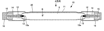
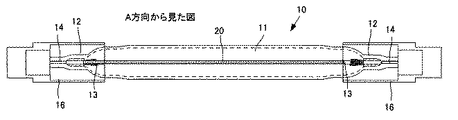
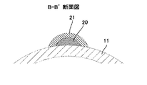
図1は本発明の実施形態にかかるロングアーク型メタルハライドランプ(以下においては、単に「メタルハライドランプ」または「ランプ」ともいう。)を発光管の管軸方向に切断した断面図である。図2は図1のメタルハライドランプをA方向から見た正面図であり、図3は図1中の線分B−B’における要部断面図である。
Hereinafter, embodiments of the present invention will be described.
FIG. 1 is a cross-sectional view of a long arc type metal halide lamp according to an embodiment of the present invention (hereinafter, also simply referred to as “metal halide lamp” or “lamp”) cut in the tube axis direction of the arc tube. FIG. 2 is a front view of the metal halide lamp of FIG. 1 as viewed from the direction A, and FIG. 3 is a cross-sectional view of a principal part taken along line BB ′ in FIG.
メタルハライドランプ10は例えば石英ガラス等の透光性材料からなる発光管11の両端に封止部12が形成されている。電極13はタングステンに酸化トリウムを含有したトリエーテッドタングステンからなり、電極13の軸部が封止部12に伸びている。封止部12には、モリブデンからなる金属箔14が埋設されており、電極軸部の端部に接続されている。この金属箔14の外側の端部には外部リード棒15が接続されている。同図において、符号16は封止部12を含み発光管11の絞込み部を囲繞する口金である。
In the
このメタルハライドランプ10には、発光管11の内部Sに少なくとも、発光物質として鉄(Fe)を少なくとも含んでいる。鉄はこの種のメタルハライドランプ10において主要な発光である波長300〜400nmの範囲の紫外光を得るために封入される必須の発光物質である。また、鉄のほかにタリウム(Tl)、錫(Sn)、亜鉛(Zn)、ビスマス(Bi)などの金属を適宜に封入することがある。更に、発光管11内部に水銀を封入しても良い。
The
発光管11の内部には、発光管11の内容積に対して0.3μmol/cc以上となるようハロゲンが封入されている。ハロゲンは具体的には沃素(I)及び/又は臭素(Br)であり、これらが従来のものに対して多量に封入されていることにより、メタルハライドとハロゲンとの反応が促進されるので、メタルハライドランプが過冷却の下で使用されたとしても、照度低下を抑制することができる。
Inside the
図1〜3に示すように、発光管11は外表面上に導電性物質からなる膜20が形成されている。導電性物質は、白金、金、銀−パラジウム合金、銅などの金属又は合金、あるいは、ITOやSnO2のような透明導電性物質である。この導電性物質よりなる膜20は、発光管11の管軸に沿って形成されており、更に一方および他方の電極13先端(13a)に対応する位置に亘って連続的に形成されている。
このように電極間に亘って導電性物質からなる膜20が形成されることにより、メタルハライドランプ10に始動用電圧が印加された際、電荷が当該膜を通じて一方の電極から他方の電極まで速やかに移動することができ、発光管11内部において電極間で絶縁破壊するよりも、電圧を低下させることができて、始動特性を良好なものとすることができるようになる。
As shown in FIGS. 1-3, the
Thus, by forming the
また、この導電性物質からなる膜20の上には、図3に示すようにその全てを覆うようにシリカ粒子やアルミナ粒子からなる保護層21が設けられているのが好ましい。かかる保護層21は、粒子状のシリカ及び/又はアルミナに適宜のバインダ及び有機溶剤を混合して懸濁液を作製し、予め設けておいた導電性物質からなる膜20の上に塗布し、乾燥、焼成して形成される。なおシリカとアルミナは単体で用いてもよいし適宜の割合で混合してもよい。
このような保護層21が具備されていることで、メタルハライドランプ10の発光管11が過熱状態となった場合にも導電性物質が酸化して導電性が損なわれることがなく、また、冷却風が周囲を流過することで膜20が飛散して消失したりすることを防止することができる。
このような保護層21について、耐熱性の観点からいうと、導電性物質の膜のみを配置した場合には耐熱温度は800℃程度であるが、シリカ粒子又はアルミナ粒子からなる保護層21が形成されることで、耐熱性を約1000℃程度まで高くすることができるようになる。これは、本発明に係るメタルハライドランプのように、擬似的な間欠点灯で点灯され、更にシャッタ機構によって冷却作用にむらが生じるような場合は特に、発光管11の温度制御が難しいことが多いものであるが有効に作用する。
Further, it is preferable that a
With such a
With respect to such a
図4は、メタルハライドランプと反射ミラーの位置関係を説明する図であり、ランプの管軸に対して垂直に切断した断面図である。
図4に示すように、メタルハライドランプ10に形成された導電性物質からなる膜20は反射ミラー22,23の中央上部の通風口24に沿って形成されており、特に膜20の幅(発光管周方向の幅)が通風口24の開口幅よりも小さくなるよう形成されている。
このように、メタルハライドランプ10の背部にある通風口24に沿って導電性物質からなる膜20が形成されることで、当該膜20がランプ10から放射する光を遮光することなく、始動用の導電膜としての機能を発揮することができる。しかも、かかる導電性物質からなる膜20が形成された部分は、その背後に通風口が形成されているためミラー22,23による反射が行われないため、光の利用効率を低下させることがない。
FIG. 4 is a diagram for explaining the positional relationship between the metal halide lamp and the reflecting mirror, and is a cross-sectional view cut perpendicular to the tube axis of the lamp.
As shown in FIG. 4, the
As described above, the
このようなメタルハライドランプを備えた光照射装置によれば、ランプに封入されたハロゲン量が0.3mol/cc以上に増大されているためメタルハライドとハロゲンとの反応が促進されて照度維持率を高く維持することができ、しかもハロゲン量が増大されたことによる始動性の低下もなく、更にランプ点灯初期の照度においても低下することがない。 According to the light irradiation apparatus equipped with such a metal halide lamp, the amount of halogen enclosed in the lamp is increased to 0.3 mol / cc or more, so that the reaction between the metal halide and the halogen is promoted and the illuminance maintenance rate is increased. It can be maintained, and there is no decrease in startability due to an increase in the halogen content, and there is no decrease in illuminance at the beginning of lamp operation.
[実施例]
図1,2の構成に従い、下記に示す仕様のロングアーク型のメタルハライドランプを作製した。
発光管は、材質は石英ガラス製であり、外径がφ26.1mm、内径がφ22.5mm(肉厚1.8mm)、発光長(電極間距離)が1100mmであった。電極は酸化トリウムが添加されたタングステンからなり、発光管の内部に水銀1.0μmol/cc、鉄0.2μmol/cc、キセノンガス67kPa(50torr)封入した。なお定格電力は18kW、ランプ入力電力は160W/cmであった。
更に、発光管の内部にヨウ素を0.3μmol/ccと0.4μmol/ccとして、ハロゲンの封入量を異ならせたランプ1,2を製作した。
これらのメタルハライドランプは、それぞれ発光管の外表面上に幅が1mm、長さ1104mmとなる銀−パラジウム合金からなる膜を形成した。
[Example]
According to the configuration of FIGS. 1 and 2, a long arc type metal halide lamp having the following specifications was produced.
The arc tube was made of quartz glass, had an outer diameter of φ26.1 mm, an inner diameter of φ22.5 mm (wall thickness 1.8 mm), and a light emission length (distance between electrodes) of 1100 mm. The electrode was made of tungsten to which thorium oxide was added, and mercury was sealed at 1.0 μmol / cc, iron 0.2 μmol / cc, and xenon gas 67 kPa (50 torr) inside the arc tube. The rated power was 18 kW and the lamp input power was 160 W / cm.
Furthermore, lamps 1 and 2 were produced in which the amount of halogen enclosed was different by setting iodine to 0.3 μmol / cc and 0.4 μmol / cc inside the arc tube.
Each of these metal halide lamps was formed with a silver-palladium alloy film having a width of 1 mm and a length of 1104 mm on the outer surface of the arc tube.
上記の通りに製作した2種類のメタルハライドランプを、図4で示したような位置関係をもってランプハウス(不図示)内に取り付けて光照射装置を構成した。なお、反射ミラーは、内面に誘電体多層膜により形成された紫外線を反射し、可視光および赤外光を反射するコールドミラーが形成されたものである。 The two types of metal halide lamps manufactured as described above were mounted in a lamp house (not shown) with the positional relationship shown in FIG. The reflection mirror is formed with a cold mirror that reflects ultraviolet light formed by a dielectric multilayer film on the inner surface and reflects visible light and infrared light.
[参照例]
更に、ハロゲンの封入量が従来製品と同程度の0.2μmol/ccとしたことを除いて、上記実施例にかかるメタルハライドランプと同じ仕様の参照例にかかるランプ3を製作し、更に光照射装置を構成した。
[Reference example]
Furthermore, a lamp 3 according to a reference example having the same specifications as the metal halide lamp according to the above embodiment is manufactured except that the amount of halogen enclosed is 0.2 μmol / cc, which is about the same as that of the conventional product. Configured.
上記実施例及び参照例にかかるメタルハライドランプ1〜3について、定格消費電力と、定格消費電力に対して約50%以下となるような電力との二段階に30秒毎に切り替えて点灯することを行い、照度維持率の変化を検証した。 For the metal halide lamps 1 to 3 according to the above embodiment and the reference example, the lighting is performed by switching every 30 seconds in two stages of rated power consumption and power that is about 50% or less with respect to the rated power consumption. And verified the change in the illuminance maintenance rate.
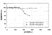
図5に、照度維持率の結果を示す。
同図はハロゲン量を0.4μmol/ccとして封入した実施例(ランプ2)と、ハロゲン量を0.2μmol/ccとして封入した参照例(ランプ3)のものである。同図から明らかなように、ハロゲン量を0.4μmol/ccとした実施例のランプによると、点灯後700時間を経過しても照度維持率が90%以上を維持しており、長い使用寿命が得られると判明した。なお同図では示さなかったがハロゲン量0.3μmol/ccとして封入した実施例のものも、700時間点灯後の照度維持率は83%以上を維持したことが確認されており、700時間以上点灯しても市場要求である照度維持率80%を上回るという結果が得られた。
一方、ハロゲンの封入量が従来技術にかかるものと同程度の参照例にかかるランプ3は、300時間を超えて点灯すると急速に照度が低下した。この理由はシャッタ制御に由来し、冷却条件が安定化しないために過冷却状態が発生し、ハロゲンの反応特性が低下したためと推定される。
FIG. 5 shows the results of the illuminance maintenance rate.
The figure shows an example (lamp 2) in which the halogen amount is sealed at 0.4 μmol / cc and a reference example (lamp 3) in which the halogen amount is sealed at 0.2 μmol / cc. As is clear from the figure, according to the lamp of the example in which the halogen amount was 0.4 μmol / cc, the illuminance maintenance rate was maintained at 90% or more even after 700 hours had elapsed since lighting, and the long service life Was found to be obtained. Although not shown in the figure, it was confirmed that the illuminance maintenance rate after lighting for 700 hours was also maintained at 83% or more for the example sealed with a halogen amount of 0.3 μmol / cc, and lighting for 700 hours or more. Even so, the result was that the illuminance maintenance rate of 80%, which is a market requirement, was exceeded.
On the other hand, the illuminance of the lamp 3 according to the reference example having the same amount of halogen encapsulated as that of the related art rapidly decreased when turned on for more than 300 hours. The reason for this is derived from the shutter control, and it is presumed that the cooling conditions are not stabilized, a supercooling state occurs, and the reaction characteristics of the halogen deteriorate.
続いて、発光管内に封入されるハロゲン量と始動特性について検証を行った。
先に示した実施例及び参照例にかかるランプ1〜3のそれぞれと、導電性物質からなる膜を具備していない点を除き同じ仕様として比較例にかかるランプ4〜6を製作した。なお、ランプ4のハロゲン量は0.3μmol/cc、ランプ5のハロゲン量は0.4μmol/cc、ランプ6のハロゲン量は0.2μmol/ccであった。
Subsequently, the amount of halogen sealed in the arc tube and the starting characteristics were verified.
The lamps 4 to 6 according to the comparative example were manufactured with the same specifications except that each of the lamps 1 to 3 according to the example and the reference example described above was not provided with a film made of a conductive material. The halogen amount of the lamp 4 was 0.3 μmol / cc, the halogen amount of the lamp 5 was 0.4 μmol / cc, and the halogen amount of the lamp 6 was 0.2 μmol / cc.
上述したランプ1〜3、および、導電性物質からなる膜を具備していないランプ4〜6の始動特性を、絶縁破壊電圧を測定することによって確認した。なお、絶縁破壊電圧測定においては、KIKUSUI製 WITHSTANDING VOLTAGE TESTER TOS5101を用いて測定し、メタルハライドランプの点灯条件としては100V/秒の条件で昇圧して絶縁破壊に至る電圧を計測することによった。
この結果を表1に示す。
The starting characteristics of the lamps 1 to 3 described above and the lamps 4 to 6 that do not have a film made of a conductive material were confirmed by measuring the dielectric breakdown voltage. In the dielectric breakdown voltage measurement, measurement was performed by using a WITHSTANDING VOLTAGE TESTER TOS 5101 manufactured by KIKUSUI, and the lighting condition of the metal halide lamp was measured by increasing the voltage under the condition of 100 V / second and measuring the voltage leading to the dielectric breakdown.
The results are shown in Table 1.
この結果から明らかなように、照度維持率において良好な結果が得られるハロゲンの封入量、すなわち0.3μmol/cc以上を満足しようとすると、発光管に導電性物質からなる膜が形成されていない場合は2.0kVを超える電圧を供給しなければならなかった。
これに対し、本願発明にかかるランプのように導電性物質からなる膜を設けたメタルはライドランプによれば、膜を設けない場合に比較して、ハロゲン量が0.3μmol/ccである場合は75%程度まで抑えることができた。ハロゲン量を増量して0.4mol/ccした場合には始動電圧が2倍程度に高くなるが、導電性物質からなる膜を形成することでこれを半分程度まで抑えることができ、始動特性を損なうことなくランプの使用寿命を延ばすことができると判明した。
As is clear from this result, when an attempt is made to satisfy the amount of halogen encapsulated that gives a satisfactory result in the illuminance maintenance rate, that is, 0.3 μmol / cc or more, a film made of a conductive material is not formed on the arc tube. In some cases, a voltage exceeding 2.0 kV had to be supplied.
On the other hand, a metal provided with a film made of a conductive material, such as a lamp according to the present invention, has a halogen amount of 0.3 μmol / cc according to a ride lamp as compared to a case where no film is provided. Was reduced to about 75%. When the amount of halogen is increased to 0.4 mol / cc, the starting voltage becomes about twice as high, but by forming a film made of a conductive material, this can be suppressed to about half, and the starting characteristics are improved. It has been found that the service life of the lamp can be extended without loss.
以上の結果から明らかなように、本発明に係るメタルハライドランプによれば、発光管の内部に封入されるハロゲンの濃度を0.3μmol/cc以上とすることで、初期照度に対する照度維持率を高い状態に長時間維持することができ、しかも、ランプの始動特性を改善することができるようになる。
更に、ハロゲンの濃度を0.4μmol/cc以上にすることで初期照度に対する照度維持率を一層高い状態に長時間維持することができ、始動特性においても、導電性物質からなる膜を備えていないものに比較して約半分程度まで電圧を低く抑えることができる。
As is apparent from the above results, according to the metal halide lamp of the present invention, the illuminance maintenance rate with respect to the initial illuminance is high by setting the concentration of halogen enclosed in the arc tube to 0.3 μmol / cc or more. The state can be maintained for a long time, and the starting characteristics of the lamp can be improved.
Furthermore, by setting the halogen concentration to 0.4 μmol / cc or more, the illuminance maintenance ratio with respect to the initial illuminance can be maintained for a long time, and the film made of a conductive material is not provided in starting characteristics. The voltage can be kept down to about half compared to the one.
10 メタルハライドランプ
11 発光管
12 封止部
13 電極
14 金属箔
15 外部リード棒
16 口金
20 導電性物質からなる膜
21 保護層
22、23 反射ミラー
DESCRIPTION OF
Claims (3)
前記ハロゲンは、発光管の内容積に対して0.3μmol/cc以上封入されてなり、
前記発光管の外表面上に、当該発光管の管軸に沿って、一方と他方の電極間に亘って形成された導電性物質からなる膜が設けられていることを特徴とするメタルハライドランプ。 A metal halide lamp in which a pair of electrodes are arranged opposite to each other inside an ultraviolet ray transmissive arc tube, and iron and halogen are enclosed,
The halogen is sealed 0.3 μmol / cc or more with respect to the inner volume of the arc tube,
A metal halide lamp, wherein a film made of a conductive material formed between one and the other electrode along the tube axis of the arc tube is provided on the outer surface of the arc tube.
このメタルハライドランプおよび反射ミラーを通風により冷却する冷却機構とを具備してなる光照射装置であって、
前記反射ミラーは冷却風用の開口を有し、
前記メタルハライドランプは前記導電性物質からなる膜が前記反射ミラーの開口に向かって配置されている
ことを特徴とする光照射装置。 The metal halide lamp according to claim 1 or 2, and a substantially bowl-shaped reflecting mirror that covers the metal halide lamp,
A light irradiation device comprising the metal halide lamp and a cooling mechanism for cooling the reflection mirror by ventilation,
The reflection mirror has an opening for cooling air;
In the metal halide lamp, the film made of the conductive material is disposed toward the opening of the reflection mirror.
Priority Applications (1)
| Application Number | Priority Date | Filing Date | Title |
|---|---|---|---|
| JP2011076072A JP2012209227A (en) | 2011-03-30 | 2011-03-30 | Long arc type metal halide lamp and light irradiation device |
Applications Claiming Priority (1)
| Application Number | Priority Date | Filing Date | Title |
|---|---|---|---|
| JP2011076072A JP2012209227A (en) | 2011-03-30 | 2011-03-30 | Long arc type metal halide lamp and light irradiation device |
Publications (1)
| Publication Number | Publication Date |
|---|---|
| JP2012209227A true JP2012209227A (en) | 2012-10-25 |
Family
ID=47188783
Family Applications (1)
| Application Number | Title | Priority Date | Filing Date |
|---|---|---|---|
| JP2011076072A Withdrawn JP2012209227A (en) | 2011-03-30 | 2011-03-30 | Long arc type metal halide lamp and light irradiation device |
Country Status (1)
| Country | Link |
|---|---|
| JP (1) | JP2012209227A (en) |
Cited By (2)
| Publication number | Priority date | Publication date | Assignee | Title |
|---|---|---|---|---|
| JP2017182928A (en) * | 2016-03-28 | 2017-10-05 | 東芝ライテック株式会社 | Discharge lamp |
| CN111073539A (en) * | 2019-09-06 | 2020-04-28 | 深圳科诺桥科技股份有限公司 | Light reflecting structure and preparation method thereof |
-
2011
- 2011-03-30 JP JP2011076072A patent/JP2012209227A/en not_active Withdrawn
Cited By (2)
| Publication number | Priority date | Publication date | Assignee | Title |
|---|---|---|---|---|
| JP2017182928A (en) * | 2016-03-28 | 2017-10-05 | 東芝ライテック株式会社 | Discharge lamp |
| CN111073539A (en) * | 2019-09-06 | 2020-04-28 | 深圳科诺桥科技股份有限公司 | Light reflecting structure and preparation method thereof |
Similar Documents
| Publication | Publication Date | Title |
|---|---|---|
| CN100449678C (en) | Short arc ultra-high pressure mercury lamp | |
| JPS5954167A (en) | High voltage discharge lamp of low output | |
| TWI497560B (en) | Ultraviolet ray irradiation apparatus, ultraviolet irradiation method, and ultraviolet ray irradiation apparatus | |
| CN100377287C (en) | A fluorescent lamp and its manufacturing method | |
| JP2003173763A (en) | Mercury-free arc tube for discharge lamp device | |
| JP2012209227A (en) | Long arc type metal halide lamp and light irradiation device | |
| JP2012198997A (en) | Long arc metal halide lamp and light irradiation device | |
| TW201021079A (en) | Metal halide lamp | |
| JP4300950B2 (en) | Light source device | |
| JP2015084337A (en) | Light radiation device | |
| JP3395515B2 (en) | Short arc type metal halide lamp | |
| JP5672030B2 (en) | Long arc metal halide lamp and metal halide lamp lighting device | |
| CN100524009C (en) | Light source device | |
| TW200832491A (en) | Ultraviolet discharge lamp | |
| CN101587817A (en) | A metal halide lamp | |
| KR100840798B1 (en) | Short arc type discharge lamp lighting device, ultraviolet light irradiation device and ultraviolet light irradiation method | |
| CN102214544A (en) | Short arc dimmable HID lamp with constant colour during dimming | |
| JPH0992227A (en) | Fluorescent lamps and lighting devices | |
| JP2002245967A (en) | High pressure discharge lamp, high pressure discharge lamp lighting device and lighting device | |
| JP2003100253A (en) | High pressure metal vapor discharge lamps and lighting equipment | |
| JP4013849B2 (en) | Light source device | |
| JP2005283754A (en) | Optical devices and parts | |
| JP2005149968A (en) | Light source device | |
| JP2007273134A (en) | Light source device | |
| JP2006019150A (en) | Light source device |
Legal Events
| Date | Code | Title | Description |
|---|---|---|---|
| A300 | Withdrawal of application because of no request for examination |
Free format text: JAPANESE INTERMEDIATE CODE: A300 Effective date: 20140603 |