JP2012209247A - In-vehicle battery - Google Patents
In-vehicle battery Download PDFInfo
- Publication number
- JP2012209247A JP2012209247A JP2012028462A JP2012028462A JP2012209247A JP 2012209247 A JP2012209247 A JP 2012209247A JP 2012028462 A JP2012028462 A JP 2012028462A JP 2012028462 A JP2012028462 A JP 2012028462A JP 2012209247 A JP2012209247 A JP 2012209247A
- Authority
- JP
- Japan
- Prior art keywords
- battery
- vehicle
- battery module
- module
- height
- Prior art date
- Legal status (The legal status is an assumption and is not a legal conclusion. Google has not performed a legal analysis and makes no representation as to the accuracy of the status listed.)
- Granted
Links
Images


Classifications
-
- H—ELECTRICITY
- H01—ELECTRIC ELEMENTS
- H01M—PROCESSES OR MEANS, e.g. BATTERIES, FOR THE DIRECT CONVERSION OF CHEMICAL ENERGY INTO ELECTRICAL ENERGY
- H01M10/00—Secondary cells; Manufacture thereof
- H01M10/60—Heating or cooling; Temperature control
- H01M10/62—Heating or cooling; Temperature control specially adapted for specific applications
- H01M10/625—Vehicles
-
- B—PERFORMING OPERATIONS; TRANSPORTING
- B60—VEHICLES IN GENERAL
- B60R—VEHICLES, VEHICLE FITTINGS, OR VEHICLE PARTS, NOT OTHERWISE PROVIDED FOR
- B60R16/00—Electric or fluid circuits specially adapted for vehicles and not otherwise provided for; Arrangement of elements of electric or fluid circuits specially adapted for vehicles and not otherwise provided for
- B60R16/02—Electric or fluid circuits specially adapted for vehicles and not otherwise provided for; Arrangement of elements of electric or fluid circuits specially adapted for vehicles and not otherwise provided for electric constitutive elements
- B60R16/04—Arrangement of batteries
-
- B—PERFORMING OPERATIONS; TRANSPORTING
- B60—VEHICLES IN GENERAL
- B60L—PROPULSION OF ELECTRICALLY-PROPELLED VEHICLES; SUPPLYING ELECTRIC POWER FOR AUXILIARY EQUIPMENT OF ELECTRICALLY-PROPELLED VEHICLES; ELECTRODYNAMIC BRAKE SYSTEMS FOR VEHICLES IN GENERAL; MAGNETIC SUSPENSION OR LEVITATION FOR VEHICLES; MONITORING OPERATING VARIABLES OF ELECTRICALLY-PROPELLED VEHICLES; ELECTRIC SAFETY DEVICES FOR ELECTRICALLY-PROPELLED VEHICLES
- B60L1/00—Supplying electric power to auxiliary equipment of vehicles
- B60L1/02—Supplying electric power to auxiliary equipment of vehicles to electric heating circuits
-
- B—PERFORMING OPERATIONS; TRANSPORTING
- B60—VEHICLES IN GENERAL
- B60L—PROPULSION OF ELECTRICALLY-PROPELLED VEHICLES; SUPPLYING ELECTRIC POWER FOR AUXILIARY EQUIPMENT OF ELECTRICALLY-PROPELLED VEHICLES; ELECTRODYNAMIC BRAKE SYSTEMS FOR VEHICLES IN GENERAL; MAGNETIC SUSPENSION OR LEVITATION FOR VEHICLES; MONITORING OPERATING VARIABLES OF ELECTRICALLY-PROPELLED VEHICLES; ELECTRIC SAFETY DEVICES FOR ELECTRICALLY-PROPELLED VEHICLES
- B60L50/00—Electric propulsion with power supplied within the vehicle
- B60L50/50—Electric propulsion with power supplied within the vehicle using propulsion power supplied by batteries or fuel cells
- B60L50/51—Electric propulsion with power supplied within the vehicle using propulsion power supplied by batteries or fuel cells characterised by AC-motors
-
- B—PERFORMING OPERATIONS; TRANSPORTING
- B60—VEHICLES IN GENERAL
- B60L—PROPULSION OF ELECTRICALLY-PROPELLED VEHICLES; SUPPLYING ELECTRIC POWER FOR AUXILIARY EQUIPMENT OF ELECTRICALLY-PROPELLED VEHICLES; ELECTRODYNAMIC BRAKE SYSTEMS FOR VEHICLES IN GENERAL; MAGNETIC SUSPENSION OR LEVITATION FOR VEHICLES; MONITORING OPERATING VARIABLES OF ELECTRICALLY-PROPELLED VEHICLES; ELECTRIC SAFETY DEVICES FOR ELECTRICALLY-PROPELLED VEHICLES
- B60L50/00—Electric propulsion with power supplied within the vehicle
- B60L50/50—Electric propulsion with power supplied within the vehicle using propulsion power supplied by batteries or fuel cells
- B60L50/60—Electric propulsion with power supplied within the vehicle using propulsion power supplied by batteries or fuel cells using power supplied by batteries
- B60L50/64—Constructional details of batteries specially adapted for electric vehicles
-
- B—PERFORMING OPERATIONS; TRANSPORTING
- B60—VEHICLES IN GENERAL
- B60L—PROPULSION OF ELECTRICALLY-PROPELLED VEHICLES; SUPPLYING ELECTRIC POWER FOR AUXILIARY EQUIPMENT OF ELECTRICALLY-PROPELLED VEHICLES; ELECTRODYNAMIC BRAKE SYSTEMS FOR VEHICLES IN GENERAL; MAGNETIC SUSPENSION OR LEVITATION FOR VEHICLES; MONITORING OPERATING VARIABLES OF ELECTRICALLY-PROPELLED VEHICLES; ELECTRIC SAFETY DEVICES FOR ELECTRICALLY-PROPELLED VEHICLES
- B60L50/00—Electric propulsion with power supplied within the vehicle
- B60L50/50—Electric propulsion with power supplied within the vehicle using propulsion power supplied by batteries or fuel cells
- B60L50/60—Electric propulsion with power supplied within the vehicle using propulsion power supplied by batteries or fuel cells using power supplied by batteries
- B60L50/66—Arrangements of batteries
-
- B—PERFORMING OPERATIONS; TRANSPORTING
- B60—VEHICLES IN GENERAL
- B60L—PROPULSION OF ELECTRICALLY-PROPELLED VEHICLES; SUPPLYING ELECTRIC POWER FOR AUXILIARY EQUIPMENT OF ELECTRICALLY-PROPELLED VEHICLES; ELECTRODYNAMIC BRAKE SYSTEMS FOR VEHICLES IN GENERAL; MAGNETIC SUSPENSION OR LEVITATION FOR VEHICLES; MONITORING OPERATING VARIABLES OF ELECTRICALLY-PROPELLED VEHICLES; ELECTRIC SAFETY DEVICES FOR ELECTRICALLY-PROPELLED VEHICLES
- B60L58/00—Methods or circuit arrangements for monitoring or controlling batteries or fuel cells, specially adapted for electric vehicles
- B60L58/10—Methods or circuit arrangements for monitoring or controlling batteries or fuel cells, specially adapted for electric vehicles for monitoring or controlling batteries
- B60L58/18—Methods or circuit arrangements for monitoring or controlling batteries or fuel cells, specially adapted for electric vehicles for monitoring or controlling batteries of two or more battery modules
- B60L58/21—Methods or circuit arrangements for monitoring or controlling batteries or fuel cells, specially adapted for electric vehicles for monitoring or controlling batteries of two or more battery modules having the same nominal voltage
-
- B—PERFORMING OPERATIONS; TRANSPORTING
- B60—VEHICLES IN GENERAL
- B60L—PROPULSION OF ELECTRICALLY-PROPELLED VEHICLES; SUPPLYING ELECTRIC POWER FOR AUXILIARY EQUIPMENT OF ELECTRICALLY-PROPELLED VEHICLES; ELECTRODYNAMIC BRAKE SYSTEMS FOR VEHICLES IN GENERAL; MAGNETIC SUSPENSION OR LEVITATION FOR VEHICLES; MONITORING OPERATING VARIABLES OF ELECTRICALLY-PROPELLED VEHICLES; ELECTRIC SAFETY DEVICES FOR ELECTRICALLY-PROPELLED VEHICLES
- B60L58/00—Methods or circuit arrangements for monitoring or controlling batteries or fuel cells, specially adapted for electric vehicles
- B60L58/10—Methods or circuit arrangements for monitoring or controlling batteries or fuel cells, specially adapted for electric vehicles for monitoring or controlling batteries
- B60L58/24—Methods or circuit arrangements for monitoring or controlling batteries or fuel cells, specially adapted for electric vehicles for monitoring or controlling batteries for controlling the temperature of batteries
- B60L58/27—Methods or circuit arrangements for monitoring or controlling batteries or fuel cells, specially adapted for electric vehicles for monitoring or controlling batteries for controlling the temperature of batteries by heating
-
- H—ELECTRICITY
- H01—ELECTRIC ELEMENTS
- H01M—PROCESSES OR MEANS, e.g. BATTERIES, FOR THE DIRECT CONVERSION OF CHEMICAL ENERGY INTO ELECTRICAL ENERGY
- H01M10/00—Secondary cells; Manufacture thereof
- H01M10/60—Heating or cooling; Temperature control
- H01M10/61—Types of temperature control
- H01M10/615—Heating or keeping warm
-
- H—ELECTRICITY
- H01—ELECTRIC ELEMENTS
- H01M—PROCESSES OR MEANS, e.g. BATTERIES, FOR THE DIRECT CONVERSION OF CHEMICAL ENERGY INTO ELECTRICAL ENERGY
- H01M10/00—Secondary cells; Manufacture thereof
- H01M10/60—Heating or cooling; Temperature control
- H01M10/64—Heating or cooling; Temperature control characterised by the shape of the cells
- H01M10/647—Prismatic or flat cells, e.g. pouch cells
-
- H—ELECTRICITY
- H01—ELECTRIC ELEMENTS
- H01M—PROCESSES OR MEANS, e.g. BATTERIES, FOR THE DIRECT CONVERSION OF CHEMICAL ENERGY INTO ELECTRICAL ENERGY
- H01M10/00—Secondary cells; Manufacture thereof
- H01M10/60—Heating or cooling; Temperature control
- H01M10/65—Means for temperature control structurally associated with the cells
- H01M10/656—Means for temperature control structurally associated with the cells characterised by the type of heat-exchange fluid
- H01M10/6561—Gases
- H01M10/6562—Gases with free flow by convection only
-
- H—ELECTRICITY
- H01—ELECTRIC ELEMENTS
- H01M—PROCESSES OR MEANS, e.g. BATTERIES, FOR THE DIRECT CONVERSION OF CHEMICAL ENERGY INTO ELECTRICAL ENERGY
- H01M10/00—Secondary cells; Manufacture thereof
- H01M10/60—Heating or cooling; Temperature control
- H01M10/65—Means for temperature control structurally associated with the cells
- H01M10/657—Means for temperature control structurally associated with the cells by electric or electromagnetic means
- H01M10/6571—Resistive heaters
-
- H—ELECTRICITY
- H01—ELECTRIC ELEMENTS
- H01M—PROCESSES OR MEANS, e.g. BATTERIES, FOR THE DIRECT CONVERSION OF CHEMICAL ENERGY INTO ELECTRICAL ENERGY
- H01M50/00—Constructional details or processes of manufacture of the non-active parts of electrochemical cells other than fuel cells, e.g. hybrid cells
- H01M50/20—Mountings; Secondary casings or frames; Racks, modules or packs; Suspension devices; Shock absorbers; Transport or carrying devices; Holders
- H01M50/204—Racks, modules or packs for multiple batteries or multiple cells
- H01M50/207—Racks, modules or packs for multiple batteries or multiple cells characterised by their shape
- H01M50/209—Racks, modules or packs for multiple batteries or multiple cells characterised by their shape adapted for prismatic or rectangular cells
-
- H—ELECTRICITY
- H01—ELECTRIC ELEMENTS
- H01M—PROCESSES OR MEANS, e.g. BATTERIES, FOR THE DIRECT CONVERSION OF CHEMICAL ENERGY INTO ELECTRICAL ENERGY
- H01M50/00—Constructional details or processes of manufacture of the non-active parts of electrochemical cells other than fuel cells, e.g. hybrid cells
- H01M50/20—Mountings; Secondary casings or frames; Racks, modules or packs; Suspension devices; Shock absorbers; Transport or carrying devices; Holders
- H01M50/249—Mountings; Secondary casings or frames; Racks, modules or packs; Suspension devices; Shock absorbers; Transport or carrying devices; Holders specially adapted for aircraft or vehicles, e.g. cars or trains
-
- H—ELECTRICITY
- H05—ELECTRIC TECHNIQUES NOT OTHERWISE PROVIDED FOR
- H05B—ELECTRIC HEATING; ELECTRIC LIGHT SOURCES NOT OTHERWISE PROVIDED FOR; CIRCUIT ARRANGEMENTS FOR ELECTRIC LIGHT SOURCES, IN GENERAL
- H05B2203/00—Aspects relating to Ohmic resistive heating covered by group H05B3/00
- H05B2203/02—Heaters using heating elements having a positive temperature coefficient
-
- Y—GENERAL TAGGING OF NEW TECHNOLOGICAL DEVELOPMENTS; GENERAL TAGGING OF CROSS-SECTIONAL TECHNOLOGIES SPANNING OVER SEVERAL SECTIONS OF THE IPC; TECHNICAL SUBJECTS COVERED BY FORMER USPC CROSS-REFERENCE ART COLLECTIONS [XRACs] AND DIGESTS
- Y02—TECHNOLOGIES OR APPLICATIONS FOR MITIGATION OR ADAPTATION AGAINST CLIMATE CHANGE
- Y02E—REDUCTION OF GREENHOUSE GAS [GHG] EMISSIONS, RELATED TO ENERGY GENERATION, TRANSMISSION OR DISTRIBUTION
- Y02E60/00—Enabling technologies; Technologies with a potential or indirect contribution to GHG emissions mitigation
- Y02E60/10—Energy storage using batteries
-
- Y—GENERAL TAGGING OF NEW TECHNOLOGICAL DEVELOPMENTS; GENERAL TAGGING OF CROSS-SECTIONAL TECHNOLOGIES SPANNING OVER SEVERAL SECTIONS OF THE IPC; TECHNICAL SUBJECTS COVERED BY FORMER USPC CROSS-REFERENCE ART COLLECTIONS [XRACs] AND DIGESTS
- Y02—TECHNOLOGIES OR APPLICATIONS FOR MITIGATION OR ADAPTATION AGAINST CLIMATE CHANGE
- Y02T—CLIMATE CHANGE MITIGATION TECHNOLOGIES RELATED TO TRANSPORTATION
- Y02T10/00—Road transport of goods or passengers
- Y02T10/60—Other road transportation technologies with climate change mitigation effect
- Y02T10/70—Energy storage systems for electromobility, e.g. batteries
Landscapes
- Engineering & Computer Science (AREA)
- Chemical & Material Sciences (AREA)
- Chemical Kinetics & Catalysis (AREA)
- Electrochemistry (AREA)
- General Chemical & Material Sciences (AREA)
- Power Engineering (AREA)
- Mechanical Engineering (AREA)
- Manufacturing & Machinery (AREA)
- Transportation (AREA)
- Life Sciences & Earth Sciences (AREA)
- Sustainable Development (AREA)
- Sustainable Energy (AREA)
- Aviation & Aerospace Engineering (AREA)
- Physics & Mathematics (AREA)
- Electromagnetism (AREA)
- Arrangement Or Mounting Of Propulsion Units For Vehicles (AREA)
- Battery Mounting, Suspending (AREA)
- Secondary Cells (AREA)
Abstract
【課題】加温効率を高めることが可能な車載用バッテリを提供すること。
【解決手段】本発明の車載用バッテリにあっては、車両のフロアパネルの下方に位置する第2バッテリモジュール13Cの車両前後方向側に隣接して設けられ、第2バッテリモジュール13Cよりも高い第3バッテリモジュール13Rの車両上下方向上方であって、車幅方向中央領域を除く両端領域に、第3バッテリモジュール13Rを加温する薄型ヒーターモジュール24を備えた。
【選択図】図4An in-vehicle battery capable of increasing the heating efficiency is provided.
An in-vehicle battery according to the present invention is provided adjacent to a vehicle front-rear direction side of a second battery module 13C positioned below a vehicle floor panel, and is higher than the second battery module 13C. A thin heater module 24 for heating the third battery module 13R is provided at both end regions excluding the central region in the vehicle width direction above the three battery modules 13R in the vehicle vertical direction.
[Selection] Figure 4
Description
本発明は、多数のバッテリシェルを積層して成るバッテリモジュールの温度調節などに有用な薄型ヒーターモジュールを備えた車載用バッテリに関するものである。 The present invention relates to an in-vehicle battery provided with a thin heater module useful for temperature control of a battery module formed by stacking a large number of battery shells.
このような用に供する薄型ヒーターモジュールを備えた車載用バッテリとしては従来、例えば特許文献1に記載されているようなものが知られている。
Conventionally, for example, a battery described in
この提案技術になる薄型ヒーターモジュールは、多数のバッテリモジュールを収納して構成したバッテリパックのケース外側面にヒーター本体を密接させ、このヒーター本体をヒーターユニットケースによりバッテリパックのケースに取着し、バッテリパックのケース外側面から遠いヒーター本体の面と、これに対向するヒーターユニットケースとの間に断熱シート体を介在させたものである。 The thin heater module that becomes the proposed technology has a heater main body in close contact with the outer surface of the battery pack case configured to accommodate a large number of battery modules, and the heater main body is attached to the case of the battery pack by the heater unit case. A heat insulating sheet is interposed between the surface of the heater body far from the case outer surface of the battery pack and the heater unit case facing the heater body.
しかし特許文献1に記載の薄型ヒーターモジュールは、バッテリモジュールを収納したバッテリパックのケースをヒーター本体で加温し、当該バッテリパックのケースからバッテリモジュールへの熱伝導により、バッテリモジュールを間接的に加温するものであるため、バッテリモジュールの加温効率が悪いという問題があった。
However, the thin heater module described in
本発明は、加温効率を高めることが可能な車載用バッテリを提供することを目的とする。 An object of this invention is to provide the vehicle-mounted battery which can improve heating efficiency.
上記課題を解決するため、本発明の車載用バッテリにあっては、車両のフロアパネルの下方に位置する一のバッテリモジュールの車両前後方向側に隣接して設けられ、一のバッテリモジュールよりも高い他のバッテリモジュールの車両上下方向上方であって、車幅方向中央領域を除く両端領域に、他のバッテリモジュールを加温するヒーターモジュールを備えた。 In order to solve the above-described problem, the vehicle-mounted battery according to the present invention is provided adjacent to the vehicle front-rear direction side of one battery module located below the vehicle floor panel, and is higher than the one battery module. A heater module that heats the other battery module is provided in the vehicle vertical direction above the other battery module and in both end regions excluding the central region in the vehicle width direction.
すなわち、他のバッテリモジュールは一のバッテリモジュールに比べて高さ方向に高いため、車幅方向中央については外気の影響を受けにくく冷却されにくい。そこで、ヒーターモジュールを、車幅方向中央領域を除く両端領域に設置することで、コストを削減しつつ十分な加温性能を得ることができる。また、車室内のフロアパネルの下方のスペースをバッテリモジュールの搭載スペースとして有効に利用でき、車室の快適性を損なわずに数多くのバッテリを搭載することができる。 That is, since the other battery modules are higher in the height direction than the one battery module, the center in the vehicle width direction is hardly affected by outside air and is not easily cooled. Therefore, by installing the heater module in both end regions excluding the central region in the vehicle width direction, sufficient heating performance can be obtained while reducing costs. In addition, the space below the floor panel in the vehicle interior can be effectively used as a mounting space for the battery module, and a large number of batteries can be mounted without impairing the comfort of the vehicle interior.
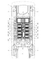
図1,2は実施例1の薄型ヒーターモジュールを適用したバッテリパックを、車両フロアパネル直下のバッテリ収納空所内に取り付けた状態で示す、車両の側面図および平面図、図3は、図1,2に示すバッテリパックを車両のバッテリ収納空所から取り外した状態で示す、バッテリパックの全体平面図である。 1 and 2 are a side view and a plan view of a vehicle showing a battery pack to which the thin heater module of the first embodiment is applied in a battery storage space directly under the vehicle floor panel, and FIG. It is the whole battery pack top view shown in the state which removed the battery pack shown in 2 from the battery storage space of a vehicle.
先ず図1〜3に示す車両用バッテリパックを説明する。図1,2において、1は車体、2は車室、3は走行用電動モータが搭載されたモータルーム、4は左右前輪、5は左右後輪、6は前席シート、7は後席シート、11は車両用バッテリパックである。 First, the vehicle battery pack shown in FIGS. 1 and 2, 1 is a vehicle body, 2 is a passenger compartment, 3 is a motor room equipped with an electric motor for traveling, 4 is front left and right wheels, 5 is left and right rear wheels, 6 is a front seat, and 7 is a rear seat. , 11 is a vehicle battery pack.
バッテリパック11は、多数のバッテリシェル12を積層して成る複数個の第1,第2,第3バッテリモジュール13FL,13FR,13CL,13CR,13Rを、図3にも示すごとく共通なバッテリパックケース14内に収納して、1ユニットに構成する。
The
更に詳述するとバッテリパック11は、図1,2に示すように左右前席シート6の下方フロアパネル部分の直下における前方左右の第1バッテリモジュール13FL,13FRと、左右後席7の下方フロアパネル部分の直下における後方の第3バッテリモジュール13Rと、左右前席シート6および左右後席7間に延在する後席足元フロアパネル部分の直下における中央左右の第2バッテリモジュール13CL,13CRとを、上記の共通なバッテリパックケース14内に収納し、1ユニットに構成する。
More specifically, as shown in FIGS. 1 and 2, the
前方左側の第1バッテリモジュール13FLは、図1〜3に示すように4個のバッテリシェル12を横置き状態で上下方向に積層したバッテリモジュールを、2個一組として車両前後方向に並置したものとし、前方右側の第1バッテリモジュール13FRも同様に、4個のバッテリシェル12を横置き状態で上下方向に積層したバッテリモジュールを、2個一組として車両前後方向に並置したものとする。
The first battery module 13FL on the left side of the front is a battery module in which four
後方の第3バッテリモジュール13Rは、図1〜3に示すように多数のバッテリシェル12を縦置き状態で車幅方向に、後席シート7の全長と略同じ長さとなるよう積層したバッテリモジュールとする。
The rear
中央左側の第2バッテリモジュール13CLは、図1〜3に示すように2個のバッテリシェル12を横置き状態で上下方向に積層したバッテリモジュールを、2個一組として車両前後方向に並置したものとし、中央右側の第2バッテリモジュール13CRも同様に、2個のバッテリシェル12を横置き状態で上下方向に積層したバッテリモジュールを、2個一組として車両前後方向に並置したものとする。
The second battery module 13CL on the left side of the center is a battery module in which two
前方左右の第1バッテリモジュール13FL,13FRはそれぞれ、図3に明示するごとく、左側の第1バッテリモジュール13FLを構成するバッテリシェル12の電極端子12aと、右側の第1バッテリモジュール13FRを構成するバッテリシェル12の電極端子12aとが相互に向かい合わせになる向きに配置する。
As shown in FIG. 3, the front left and right first battery modules 13FL and 13FR are respectively the
また後方の第3バッテリモジュール13Rは、図3に明示するごとく、これを構成するバッテリシェル12の電極端子12aが全て車両前方に指向するよう配置する。
Further, as clearly shown in FIG. 3, the rear
更に、中央左右の第2バッテリモジュール13CL,13CRはそれぞれ、図3に明示するごとく、左側の第2バッテリモジュール13CLを構成するバッテリシェル12の電極端子12aと、右側の第2バッテリモジュール13CRを構成するバッテリシェル12の電極端子12aとが相互に向かい合わせになる向きに配置する。
Further, as clearly shown in FIG. 3, the second battery modules 13CL and 13CR at the center left and right respectively constitute the
そして、各バッテリモジュール13FL,13FR,13CL,13CR,13Rを構成するバッテリシェル12の電極端子12aはそれぞれ、図2,3に示すように、前方左右の第1バッテリモジュール13FL,13FR間における車幅方向中程スペース、および中央左右の第2バッテリモジュール13CL,13CR間における車幅方向中程スペースに配索した電源ケーブルを介して、モータルーム3内における電動モータ(インバータ)からのモータ給電線15に接続する。
The
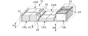
図4は実施例1のバッテリシェルの概略斜視図である。第1バッテリモジュール13FL,13FR(以下、第1バッテリモジュール13Fと記載する。)の車載時における高さをh1、第2バッテリモジュール13CL,13CR(以下、第2バッテリモジュール13Cと記載する。)の車載時における高さをh2、第3バッテリモジュール13Rの車載時における高さをh3とすると、h3>h1>h2となるように構成されている。また、これら第1〜第3バッテリモジュール13F,13C,13Rの高さ関係に略追従するように、バッテリパックケース14上面も、第2バッテリモジュール13Cの上側が最も低く形成され、次いで第1バッテリモジュール13F,第3バッテリモジュール13Rの上面が順次高く形成されている。
FIG. 4 is a schematic perspective view of the battery shell of the first embodiment. The height of the first battery modules 13FL, 13FR (hereinafter referred to as the first battery module 13F) when mounted on the vehicle is h1, and the second battery modules 13CL, 13CR (hereinafter referred to as the second battery module 13C). Assuming that the height when mounted on a vehicle is h2, and the height when the
第1バッテリモジュール13Fは左右前席シート6の下方に位置し、第3バッテリモジュール13Rは左右後席7の下方に位置していることから、第1バッテリモジュール13Fと第3バッテリモジュール13Rの高さh1とh3を、後席足元フロアパネル部分の直下に位置した第2バッテリモジュール13Cの高さh2よりも大きくすることで、車室2内のシート下方のスペースをバッテリシェル12の搭載スペースとして有効に利用でき、車室2の快適性を損なわずに数多くのバッテリを搭載することができる。また、第3バッテリモジュール13Rの高さh3が第1バッテリモジュール13Fの高さh1よりも高いことから、車室2内においてリヤシート32Rの座面がフロントシート32Fの座面より高くなる。この設定により左右後席7の乗客の良好な視界を確保できる。
Since the first battery module 13F is located below the left and right front seats 6 and the
また、第1バッテリモジュール13Fと第2バッテリモジュール13Cとのバッテリシェル12の合計数と、第3バッテリモジュール13Rのバッテリシェル12の合計数とは同じであり、一方、車両の上面視において第1バッテリモジュール13Fと第2バッテリモジュール13Cとが占有する面積よりも第3バッテリモジュール13Rが占有する面積の方が小さい。
In addition, the total number of
このことから、バッテリパック11の重心位置は車両前後方向において比較的車両後方に位置することになる。車両の前方には、走行用電動モータ等が配置されることから、バッテリパック11が比較的車両後方に重心位置を持つことで車両全体としての重量配分を前後方向における中心位置に近づけることができる。これにより、車両挙動の安定性を確保することができる。
For this reason, the center of gravity of the
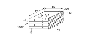
ここで、バッテリシェル12の構成との関係について説明する。図5は実施例1の第2バッテリパックの一部を表す概略図である。バッテリシェル12は、略直方体構造であり、長辺p1、短辺p2、高さp3により構成され、それぞれp1>p2>p3として構成されている。バッテリシェル12は、長辺p1と短辺p2で構成された平面121と、長辺p1と高さp3で構成された長側面122と、短辺p2と高さp3とで構成された短側面123とを有する。そして、電極端子12aは、短側面123に設けられている。
Here, the relationship with the configuration of the
第1バッテリモジュール13Fと第2バッテリモジュール13Cは、バッテリシェル12の短辺p2が車両前後方向に倣う方向に載置される。この第1バッテリモジュール13Fと第2バッテリモジュール13Cとは比較的高さ方向の制限が幅方向の制限よりも大きい領域に配置されるモジュールであることから、長辺p1を車幅方向に倣って配置したとしても、左右バッテリモジュールの間の空間を確保することができ、配線等を容易にできる。また、短辺p2を車両前後方向に倣って配置することで、バッテリシェル12の集積密度を高めることができる。また、最も短い長さである高さp3を車両上下方向に倣って配置することで、バッテリモジュールの高さを細かく調整することができる。
The first battery module 13F and the second battery module 13C are placed in a direction in which the short side p2 of the
即ち車両によって車両上下方向における制限はいろいろとあるものの、バッテリシェル12自体の構成は共通である場合、これらバッテリシェル12の積み重ね具合によって高さ調整できる。このとき、最も短い高さp3を積み重ねるため、調整単位を細かくすることで効率的にバッテリシェル12を搭載することができる。
That is, although there are various restrictions in the vehicle vertical direction depending on the vehicle, when the configuration of the
第3バッテリモジュール13Rは、バッテリシェル12の高さp3を車幅方向に倣う方向に載置される。これにより、バッテリシェル12の積層数を細かく調整できるため、左右後席シート7の下方のスペースを有効に利用して数多くのバッテリシェル12を配置することができる。
The
<薄型ヒーターモジュールについて>
次に、不使用中の凍結防止用などのために各バッテリモジュールを加温する薄型ヒーターモジュールを、図2,3に基づき以下に説明する。尚、図2,3では、明瞭のため便宜上、薄型ヒーターモジュールにハッチングを付して示した。この薄型ヒーターモジュールは所謂PTCヒーターであり、通電により所定温度まで上昇した後、その温度を維持するように抵抗値が変化するものである。このPTCヒーターと熱を均一に分布させる均熱板との組み合わせにより設定した面積の範囲に対して均等に加温することが可能に構成されている。尚、ヒーター自体は例えばニクロム線を蛇行させて配置する方法や、お湯を所定流路に沿って循環させる方法等が適用可能であり、特に限定しない。
<About the thin heater module>
Next, a thin heater module for heating each battery module to prevent freezing when not in use will be described below with reference to FIGS. 2 and 3, for the sake of clarity, the thin heater module is shown with hatching. This thin heater module is a so-called PTC heater, and its resistance value changes so as to maintain the temperature after being raised to a predetermined temperature by energization. The PTC heater and a soaking plate that uniformly distributes heat are configured to be able to uniformly heat the area range set. For example, a method of arranging the nichrome wire meandering or a method of circulating hot water along a predetermined flow path can be applied to the heater itself, and the heater is not particularly limited.
薄型ヒーターモジュール23L,23Rは、図5の斜線領域で示すようにバッテリシェル12の長側面122に設けられる。すなわち、バッテリモジュールの全体を効率よく加温するには、積層されたバッテリシェル12に対して均一に熱を伝達する必要がある。仮に薄型ヒーターモジュールを平面121に設けた場合、薄型ヒーターモジュールと近接する上端もしくは下端に積層されたバッテリシェル12のみが加温されてしまい、内部に積層されているバッテリシェル12の加温が不十分となって性能の安定化を図ることが難しい。
The
また、薄型ヒーターモジュールを短側面123に設けた場合、全てのバッテリシェル12を加温することはできるものの、薄型ヒーターモジュールに臨む面積が小さいため、加温効率が悪いといった問題がある。
Further, when the thin heater module is provided on the
そこで、実施例1では、長側面122に薄型ヒーターモジュール23L,23Rに設けることで、全てのバッテリシェル12を均一に加温すると共に、加温効率の向上を図っている。
Therefore, in the first embodiment, by providing the
前方左右の第1バッテリモジュール13FL,13FRが前記した通り、バッテリシェル12を4段重ねした大熱容量のものであるのに対し、中央左右の第2バッテリモジュール13CL,13CRが前記した通り、バッテリシェル12を2段重ねしたものであって、熱容量が小さく、温度が低下し易い。
As described above, the front left and right first battery modules 13FL and 13FR have a large heat capacity in which the
そこで、実施例1では、図2,3に示すごとく、前方左右の第1バッテリモジュール13FL,13FRについては、その前方のみに薄型ヒーターモジュール21L,21Rを設け、中央左右の第2バッテリモジュール13CL,13CRについては、その前方に薄型ヒーターモジュール22L,22Rを設けると共に、後方にも薄型ヒーターモジュール23L,23Rを設ける。尚、第1バッテリモジュール13の前方のみに薄型ヒーターモジュール21L,21Rを配置したのは、前方は走行風等の影響を受けやすく、比較的冷却されやすいからである。また、薄型ヒーターモジュールの設置領域を狭くすることで、コストを削減することができる。
Therefore, in the first embodiment, as shown in FIGS. 2 and 3, for the first battery modules 13FL and 13FR on the front left and right, the
尚、図4の矢印で示すように、第2バッテリモジュール13Cを加温する薄型ヒーターモジュール22で暖められた空気は上方に移動する。この暖気により第1バッテリモジュール13Fをも加温することができる。同様に、第2バッテリモジュール13Cを加温する薄型ヒーターモジュール23で暖められた空気は上方に移動する。この暖気により第3バッテリモジュール13Rをも加温することができる。すなわち、第2バッテリモジュール13Cは他のバッテリモジュールよりも低い位置にあるため、この位置関係を利用して他のバッテリモジュールをも加温するものである。特に、前述の如くバッテリパックケース14上面が、第1〜第3バッテリモジュール13F,13C,13Rの高さ関係に略追従するように形成されている場合は、暖められた空気が確実に第1バッテリモジュール13Fと第3バッテリモジュール13Rの上方に流れ込むため、さらに第1バッテリモジュール13Fと第3バッテリモジュール13Rの加温性能が向上する。以上の作用効果のため、第3バッテリモジュール13Rは、車幅方向中央部に薄型ヒーターモジュール24を設けなくても、十分な加温性能を得ることができる。
As shown by the arrows in FIG. 4, the air heated by the
後方の第3バッテリモジュール13Rは、第1バッテリモジュール13F及び第2バッテリモジュール13Cとは積層方向が異なるため、長側面122は車両上面側に位置するため、薄型バッテリーヒーター24も車両から見ると上面側に配置される。このとき、第3バッテリモジュール13Rは、前方左右の第1バッテリモジュール13FL,13FRよりも更にバッテリシェル12の積層数が多く、熱容量が最も大きいことから更に温度が低下し難い。ただし、車幅方向の側面側は比較的走行風等の影響を受けやすく、第3バッテリモジュール13Rの車幅方向中央付近が最も冷えにくい。このことから、後方の第3バッテリモジュール13Rについては、バッテリシェル12の積層方向両端領域であって、上方のみに薄型ヒーターモジュール24L,24Rを設ける。
The rear
更に具体的には、積層方向に3分割した領域を設定したとき、両端の領域に薄型ヒーターモジュール24L,24Rを設置し、中央の領域には設けない。これにより、薄型ヒーターモジュールの設置領域が狭くなったとしても、第3バッテリモジュール13Rを全体的に効率よく加温することができる。また、薄型ヒーターモジュールの設置領域を狭くすることで、コストを削減することができる。
More specifically, when a region divided into three in the stacking direction is set, the
薄型ヒーターモジュール21L,21Rはそれぞれ、前方左側バッテリモジュール13FLおよび前方右側バッテリモジュール13FRの前側に立てて近接配置し、バッテリパックケース14のバッテリモジュール載置面14aに取着する。
The
薄型ヒーターモジュール22L,22Rはそれぞれ、中央左側バッテリモジュール13CLおよび中央右側バッテリモジュール13CRの前側に立てて近接配置し、バッテリパックケース14のバッテリモジュール載置面14aに取着し、薄型ヒーターモジュール23L,23Rはそれぞれ、中央左側バッテリモジュール13CLおよび中央右側バッテリモジュール13CRの後側に立てて近接配置し、バッテリパックケース14のバッテリモジュール載置面14aに取着する。
The
薄型ヒーターモジュール24L,24Rはそれぞれ、後方バッテリモジュール13Rのバッテリシェル積層方向における両端の上方に近接位置し、バッテリパックケース14のバッテリモジュール載置面14aに取着する。
The
ところで、バッテリ電源ケーブルが前記した通り前方左右のバッテリモジュール13FL,13FR間における車幅方向中程スペース、および中央左右のバッテリモジュール13CL,13CR間における車幅方向中程スペースに配索されていることから、薄型ヒーターモジュール21L,21R,22L,22R,23L,23R,24L,24Rの電源接続端子はそれぞれ、前方左右のバッテリモジュール13FL,13FR間における車幅方向中程スペース、および中央左右のバッテリモジュール13CL,13CR間における車幅方向中程スペースに近い側に設置するのが良い。
By the way, as described above, the battery power cable is routed in the middle space in the vehicle width direction between the left and right battery modules 13FL and 13FR and in the middle space in the vehicle width direction in the middle between the left and right battery modules 13CL and 13CR. The power connection terminals of the
そのため、前方左側バッテリモジュール13FLおよび前方右側バッテリモジュール13FRの前側に立てて近接配置する薄型ヒーターモジュール21L,21Rの電源接続端子はそれぞれ、これら薄型ヒーターモジュール21L,21Rの相互に近い端部に配置し、また中央左側バッテリモジュール13CLおよび中央右側バッテリモジュール13CRの後側に立てて近接配置する薄型ヒーターモジュール23L,23Rの電源接続端子もそれぞれ、これら薄型ヒーターモジュール23L,23Rの相互に近い端部に配置する。
For this reason, the power connection terminals of the
従って、薄型ヒーターモジュール21L,21Rおよび薄型ヒーターモジュール23L,23Rはそれぞれ、図2,3に示すように平板状に構成することができる。
Accordingly, the
ここで、薄型ヒーターモジュール21L,21Rの電源接続端子を上記のように配置し得るのは、前方左側バッテリモジュール13FLおよび前方右側バッテリモジュール13FRの前方に、隣接するバッテリモジュールが存在しなくて、薄型ヒーターモジュール21L,21Rの相互に近い端部周辺に、電源接続端子を設置するスペースを確保し得るためである。
また薄型ヒーターモジュール23L,23Rの電源接続端子を上記のように配置し得るのは、中央左側バッテリモジュール13CLおよび中央右側バッテリモジュール13CRの後方に、隣接するバッテリモジュールが存在しなくて、薄型ヒーターモジュール23L,23Rの相互に近い端部周辺に、電源接続端子を設置するスペースを確保し得るためである。
Here, the power connection terminals of the
Further, the power connection terminals of the
以上説明したように、実施例1にあっては下記に列挙する作用効果を得ることができる。
(1)車両のフロアパネルの下方に位置する第2バッテリモジュール13C(一のバッテリモジュール)と、第2バッテリモジュール13Cの車両前後方向側に隣接して設けられ、第2バッテリモジュール13Cよりも高い第3バッテリモジュール13R(他のバッテリモジュール)とを有し、第3バッテリモジュール13Rの車両上下方向上方であって、車幅方向中央領域を除く両端領域に、第3バッテリモジュール13Rの側面と対向するように設けられ、第3バッテリモジュール13Rを加温する薄型ヒーターモジュール24(ヒータモジュール)と、を備えた。
As described above, the effects listed below can be obtained in the first embodiment.
(1) The second battery module 13C (one battery module) located below the vehicle floor panel is provided adjacent to the vehicle front-rear direction side of the second battery module 13C, and is higher than the second battery module 13C. A
すなわち、第3バッテリモジュール13Cは第2バッテリモジュール13F,13Cに比べて高いため、車幅方向中央については外気の影響を受けにくく冷却されにくい。そこで、薄型ヒーターモジュール24を、車幅方向中央領域を除く両端領域に設置することで、コストを削減しつつ十分な加温性能を得ることができる。また、車室2内のフロアパネルの下方のスペースをバッテリシェル12の搭載スペースとして有効に利用でき、車室2の快適性を損なわずに数多くのバッテリを搭載することができる。
That is, since the third battery module 13C is higher than the second battery modules 13F and 13C, the center in the vehicle width direction is hardly affected by outside air and is not easily cooled. Therefore, by installing the
(2)車両のフロアパネルの下方であって、車両前方から順に前席下方に位置し第1高さh1を有する第1バッテリモジュール13Fと、前席と後席との間の後席足元フロアパネル下方に位置し第1高さh1よりも低い第2高さh2を有する第2バッテリモジュール13Cと、後席下方に位置し第1高さh1よりも高い第3高さh3を有する第3バッテリモジュール13Rとを有するバッテリモジュールと、第3バッテリモジュール13Rの車両上下方向上方であって、第3バッテリモジュール13Rの車幅方向中央領域を除く両端領域に第3バッテリモジュール13Rの側面と対向するように設けられ、第3バッテリモジュール13Rを加温する薄型ヒーターモジュール24(ヒータモジュールに相当)と、を備えた。
(2) A first battery module 13F having a first height h1 that is located below the front seat of the vehicle and sequentially below the front seat from the front of the vehicle, and a rear seat floor between the front seat and the rear seat A second battery module 13C having a second height h2 located below the panel and lower than the first height h1, and a third battery module 13C having a third height h3 located below the rear seat and higher than the first height h1. A battery module having a
すなわち、第3バッテリモジュール13Cは後席下方に設置されることから、比較的高さ方向の制限が緩やかである。このように、制限が緩やかな部分に薄型ヒーターモジュール24を配置することで、他の制約を回避しつつ効率的に配置することができる。また、バッテリシェル12を車幅方向に積層し、その上方に薄型ヒーターモジュール24を設置することで、車幅方向のスペースを十分に確保でき、効率的にバッテリシェル12を配置することができる。また、第3バッテリモジュール13Cは第1及び第2バッテリモジュール13F,13Cに比べて容積が大きいことから熱容量も大きい。特に、車幅方向中央については外気の影響を受けにくく冷却されにくい。そこで、薄型ヒーターモジュール24を、車幅方向中央領域を除く両端領域に設置することで、コストを削減しつつ十分な加温性能を得ることができる。また、車室2内のシート下方のスペースをバッテリシェル12の搭載スペースとして有効に利用でき、車室2の快適性を損なわずに数多くのバッテリを搭載することができる。
That is, since the third battery module 13C is installed below the rear seat, the restriction in the height direction is relatively gentle. As described above, by arranging the
(3)薄型ヒーターモジュール21は、第1バッテリモジュール13Fの車両前後方向前方に配置されている。
すなわち、車両前方に配置される第1バッテリモジュール13Fは走行風等の影響を受けやすく、冷却されやすい。このように、冷却されやすい箇所のみに設置することで、加温性能を確保しつつコストを削減することができる。尚、第1バッテリモジュール13Fは第2バッテリモジュール13Cに比べて容積が大きいことから熱容量も大きい。よって、車両後方側については比較的冷却されにくいため、車両前方のみに薄型ヒーターモジュール21を設置しても十分な加温性能を得ることができる。尚、第1バッテリモジュール13Fは、前席の下方に設置されることから、高さ方向を確保しにくい。そこで、バッテリシェル12を車両上下方向に沿って積層し、長側面122を車幅方向に沿って配置することで、効率的にバッテリシェル12を配置することができる。
(3) The
That is, the first battery module 13F disposed in front of the vehicle is easily affected by traveling wind or the like and is easily cooled. Thus, by installing only in the location where it is easy to cool, cost can be reduced, ensuring heating performance. Since the first battery module 13F has a larger volume than the second battery module 13C, the heat capacity is also large. Therefore, since the rear side of the vehicle is relatively difficult to cool, even if the
(4)薄型ヒーターモジュール22,23は、第2バッテリモジュール13Cの車両前後方向前方及び後方に配置される。
すなわち、第2バッテリモジュール13Cはバッテリパック11の中央部分にあるものの、他のバッテリモジュールに比べて容積が小さいことから熱容量も小さく、冷却されやすい。そこで、車両前後方向前方及び後方の両方に薄型ヒーターモジュール21を配置することで、加温性能を確保することができる。尚、第2バッテリモジュール13Fは、前席と後席との間の後席足元フロアパネル下方に設置されることから、高さ方向を確保しにくい。そこで、バッテリシェル12を車両上下方向に沿って積層し、長側面122を車幅方向に沿って配置することで、効率的にバッテリシェル12を配置することができる。
(4) The
That is, although the second battery module 13C is in the center portion of the
(5)バッテリモジュール13F,13C,13Rは、三辺を有する直方体のバッテリシェル12を複数積層して構成され、薄型ヒーターモジュール21,22,23,24は、バッテリモジュール13の積層方向に沿った辺を含む側面と対向するように立設されている。
すなわち、積層方向に沿った辺を含む側面と対向するように薄型ヒーターモジュール21,22,23,24に設けることで、全てのバッテリシェル12を均一に加温すると共に、バッテリパックケース14の内部において加温するため、加温効率の向上を図ることができる。
(5) The
That is, by providing the
(6)バッテリシェル12は、長辺p1と、短辺p2と、これら両辺より短い高さp3を有する直方体形状であり、積層方向は高さp3方向であり、薄型ヒーターモジュール21,22,23,24は、長辺p1を含む側面である長側面122と対向するように立設される。
すなわち、最も短い高さp3方向にバッテリシェル12を積層することでバッテリモジュール13の高さp3方向の長さ調整を細かく設定することができ、効率よく車両に搭載できる。また、長側面122と対向するように立設されることで、全てのバッテリシェル12を均一に加温すると共に、加温効率の向上を図ることができる。
(6) The
That is, by stacking the
1 車体
2 車室
3 モータルーム
4 左右前輪
5 左右後輪
6 前席シート
7 後席シート
11 バッテリパック
12 バッテリシェル
12a バッテリ電極端子
13FL 前方左側バッテリモジュール
13FR 前方右側バッテリモジュール
13CL 中央左側バッテリモジュール
13CR 中央右側バッテリモジュール
13R 後方バッテリモジュール
14 バッテリパックケース
14a バッテリモジュール載置面
15 モータ給電線
22L,22R 薄型ヒーターモジュール
1 body
2 compartment
3 Motor room
4 Left and right front wheels
5 Left and right rear wheels
6 Front seat
7 Rear seat
11 Battery pack
12 Battery shell
12a Battery electrode terminal
13FL front left battery module
13FR Front right battery module
13CL Center left battery module
13CR Center right battery module
13R Rear battery module
14 Battery pack case
14a Battery module mounting surface
15 Motor feed line
22L, 22R Thin heater module
Claims (6)
前記他のバッテリモジュールの車両上下方向上方であって、車幅方向中央領域を除く両端領域に、前記他のバッテリモジュールの側面と対向するように設けられ、前記他のバッテリモジュールを加温するヒーターモジュールと、
を備えたことを特徴とする車載用バッテリ。 One battery module located below the floor panel of the vehicle, and another battery module provided adjacent to the vehicle front-rear direction side of the one battery module and higher than the one battery module,
A heater that heats the other battery module provided above the other battery module in the vehicle vertical direction, in both end regions excluding the central region in the vehicle width direction so as to face the side surface of the other battery module. Module,
A vehicle-mounted battery comprising:
前記第3バッテリモジュールの車両上下方向上方であって、車幅方向中央領域を除く両端領域に、前記第3バッテリモジュールの側面と対向するように設けられ、前記第3バッテリモジュールを加温するヒーターモジュールと、
を備えたことを特徴とする車載用バッテリ。 A first battery module positioned below the front seat and having a first height, in order from the front of the vehicle, below the floor panel of the vehicle, and below the floor seat floor panel between the front seat and the rear seat. A battery module having a second battery module having a second height lower than the first height; and a third battery module positioned below the rear seat and having a third height higher than the first height;
A heater that heats the third battery module and is provided above the third battery module in an up-down direction of the vehicle and in opposite end regions excluding a central region in the vehicle width direction so as to face a side surface of the third battery module. Module,
A vehicle-mounted battery comprising:
前記ヒーターモジュールは、前記第1バッテリモジュールの車両前後方向前方に配置されていることを特徴とする車載用バッテリ。 The in-vehicle battery according to claim 2,
The in-vehicle battery, wherein the heater module is disposed in front of the first battery module in the vehicle front-rear direction.
前記ヒーターモジュールは、前記第2バッテリモジュールの車両前後方向前方及び後方に配置されることを特徴とする車載用バッテリ。 The in-vehicle battery according to claim 2 or 3,
The in-vehicle battery, wherein the heater module is disposed in front of and behind the second battery module in the vehicle front-rear direction.
前記バッテリモジュールは、三辺を有する直方体のバッテリシェルを複数積層して構成され、
前記ヒーターモジュールは、前記バッテリモジュールの積層方向に沿った辺を含む側面と対向するように立設されることを特徴とする車載用バッテリ。 The in-vehicle battery according to any one of claims 2 to 4,
The battery module is configured by stacking a plurality of rectangular battery shells having three sides,
The in-vehicle battery, wherein the heater module is erected so as to face a side surface including a side along the stacking direction of the battery modules.
前記バッテリシェルは、長辺と、短辺と、これら両辺より短い高さを有する直方体形状であり、
前記積層方向は、前記高さ方向であり、
前記ヒーターモジュールは、前記長辺を含む側面と対向するように立設されることを特徴とする車載用バッテリ。 The in-vehicle battery according to claim 5,
The battery shell has a rectangular parallelepiped shape having a long side, a short side, and a height shorter than both sides,
The stacking direction is the height direction,
The in-vehicle battery, wherein the heater module is erected so as to face a side surface including the long side.
Priority Applications (10)
| Application Number | Priority Date | Filing Date | Title |
|---|---|---|---|
| JP2012028462A JP5861484B2 (en) | 2011-03-11 | 2012-02-13 | Automotive battery |
| CN201280002752.0A CN103098296B (en) | 2011-03-11 | 2012-03-07 | Vehicle battery |
| EP12757460.6A EP2685547B1 (en) | 2011-03-11 | 2012-03-07 | Vehicle battery |
| CA2810826A CA2810826C (en) | 2011-03-11 | 2012-03-07 | In-vehicle battery |
| BR112013006279A BR112013006279A2 (en) | 2011-03-11 | 2012-03-07 | embedded battery |
| RU2013114251/07A RU2545162C1 (en) | 2011-03-11 | 2012-03-07 | Vehicle-integrated accumulator battery |
| PCT/JP2012/055744 WO2012124555A1 (en) | 2011-03-11 | 2012-03-07 | Vehicle battery |
| MX2013003569A MX2013003569A (en) | 2011-03-11 | 2012-03-07 | Vehicle battery. |
| KR1020137005654A KR101465919B1 (en) | 2011-03-11 | 2012-03-07 | In-vehicle battery |
| US13/821,460 US9321416B2 (en) | 2011-03-11 | 2012-03-07 | In-vehicle battery |
Applications Claiming Priority (3)
| Application Number | Priority Date | Filing Date | Title |
|---|---|---|---|
| JP2011054090 | 2011-03-11 | ||
| JP2011054090 | 2011-03-11 | ||
| JP2012028462A JP5861484B2 (en) | 2011-03-11 | 2012-02-13 | Automotive battery |
Publications (2)
| Publication Number | Publication Date |
|---|---|
| JP2012209247A true JP2012209247A (en) | 2012-10-25 |
| JP5861484B2 JP5861484B2 (en) | 2016-02-16 |
Family
ID=46830628
Family Applications (1)
| Application Number | Title | Priority Date | Filing Date |
|---|---|---|---|
| JP2012028462A Active JP5861484B2 (en) | 2011-03-11 | 2012-02-13 | Automotive battery |
Country Status (10)
| Country | Link |
|---|---|
| US (1) | US9321416B2 (en) |
| EP (1) | EP2685547B1 (en) |
| JP (1) | JP5861484B2 (en) |
| KR (1) | KR101465919B1 (en) |
| CN (1) | CN103098296B (en) |
| BR (1) | BR112013006279A2 (en) |
| CA (1) | CA2810826C (en) |
| MX (1) | MX2013003569A (en) |
| RU (1) | RU2545162C1 (en) |
| WO (1) | WO2012124555A1 (en) |
Cited By (2)
| Publication number | Priority date | Publication date | Assignee | Title |
|---|---|---|---|---|
| JP2014093207A (en) * | 2012-11-05 | 2014-05-19 | Nissan Motor Co Ltd | Battery temperature adjusting device |
| US9872226B2 (en) | 2014-11-25 | 2018-01-16 | Fujitsu Limited | Wireless access system and fixed terminal control apparatus |
Families Citing this family (10)
| Publication number | Priority date | Publication date | Assignee | Title |
|---|---|---|---|---|
| JP2012190691A (en) * | 2011-03-11 | 2012-10-04 | Nissan Motor Co Ltd | Battery module |
| KR101575427B1 (en) * | 2013-12-18 | 2015-12-07 | 현대자동차주식회사 | Condensation preventing-method for battery pack |
| CN107887529B (en) * | 2016-09-30 | 2021-05-25 | 蜂巢能源科技有限公司 | Battery module device for battery pack |
| US10160492B2 (en) * | 2016-10-14 | 2018-12-25 | Inevit Llc | Battery junction box housing configured to direct crash forces in an electric vehicle |
| US10272758B2 (en) * | 2016-11-02 | 2019-04-30 | Proterra Inc. | Battery system of an electric vehicle |
| US11189877B2 (en) * | 2019-01-11 | 2021-11-30 | Toyota Jidosha Kabushiki Kaisha | Battery pack and vehicle for mounting the same |
| DE102019116969A1 (en) * | 2019-06-24 | 2020-12-24 | Bayerische Motoren Werke Aktiengesellschaft | Energy storage device for a motor vehicle, motor vehicle and manufacturing method |
| KR102805472B1 (en) * | 2020-06-15 | 2025-05-09 | 현대자동차주식회사 | Vehicle floor system |
| JP7501429B2 (en) * | 2021-03-30 | 2024-06-18 | マツダ株式会社 | Body structure |
| JP7810138B2 (en) * | 2023-03-27 | 2026-02-03 | トヨタ自動車株式会社 | Vehicle and vehicle control method |
Citations (12)
| Publication number | Priority date | Publication date | Assignee | Title |
|---|---|---|---|---|
| JP2000164186A (en) * | 1998-11-27 | 2000-06-16 | Matsushita Electric Ind Co Ltd | Storage battery |
| JP2000243435A (en) * | 1999-02-23 | 2000-09-08 | Ngk Insulators Ltd | Collective battery |
| JP2007213939A (en) * | 2006-02-08 | 2007-08-23 | Sanyo Electric Co Ltd | Battery pack |
| JP2008186621A (en) * | 2007-01-26 | 2008-08-14 | Panasonic Ev Energy Co Ltd | Laminated thin heater, laminated thin heater with lead wire, battery structure with heater, and heater unit |
| JP2008204708A (en) * | 2007-02-19 | 2008-09-04 | Panasonic Ev Energy Co Ltd | Heater with temperature detection device, battery structure with heater, and heater unit |
| JP2009073430A (en) * | 2007-09-24 | 2009-04-09 | Denso Corp | In-vehicle assembled battery temperature control device |
| JP2009212059A (en) * | 2008-03-06 | 2009-09-17 | Toshiba Corp | Battery device of electric light vehicle |
| JP2010238519A (en) * | 2009-03-31 | 2010-10-21 | Honda Motor Co Ltd | Battery assembly |
| JP2011006051A (en) * | 2009-05-26 | 2011-01-13 | Nissan Motor Co Ltd | Vehicle battery assembly cooling structure, and battery assembly with water jacket |
| JP2011023292A (en) * | 2009-07-17 | 2011-02-03 | Nissan Motor Co Ltd | battery pack |
| JP2012209250A (en) * | 2011-03-11 | 2012-10-25 | Nissan Motor Co Ltd | Thin heater module |
| JP2012209248A (en) * | 2011-03-11 | 2012-10-25 | Nissan Motor Co Ltd | In-vehicle battery |
Family Cites Families (17)
| Publication number | Priority date | Publication date | Assignee | Title |
|---|---|---|---|---|
| SU1388336A1 (en) * | 1985-05-16 | 1988-04-15 | Проектно-Конструкторско-Технологическое Бюро По Вагонам | Device for mounting storage battery into vehicle |
| RU2001796C1 (en) * | 1991-05-21 | 1993-10-30 | Акционерное общество "Метровагонмаш" | Storage battery box for transportation vehicles |
| JP2702372B2 (en) | 1993-03-26 | 1998-01-21 | 日本碍子株式会社 | Heating device for high temperature secondary battery |
| JP3733629B2 (en) | 1995-12-08 | 2006-01-11 | 日産自動車株式会社 | Secondary battery temperature control device |
| US5948298A (en) * | 1996-04-26 | 1999-09-07 | Ford Global Technologies, Inc. | Battery heating system |
| JP5354846B2 (en) * | 2006-08-11 | 2013-11-27 | 株式会社東芝 | Assembled battery and charging / discharging method of assembled battery |
| US7531270B2 (en) * | 2006-10-13 | 2009-05-12 | Enerdel, Inc. | Battery pack with integral cooling and bussing devices |
| JP5029263B2 (en) * | 2007-09-28 | 2012-09-19 | 三菱自動車工業株式会社 | Electric car |
| JP5098544B2 (en) * | 2007-09-28 | 2012-12-12 | 三菱自動車工業株式会社 | Battery unit |
| JP5092657B2 (en) * | 2007-09-28 | 2012-12-05 | 三菱自動車工業株式会社 | Battery unit |
| JP5194687B2 (en) * | 2007-09-28 | 2013-05-08 | 三菱自動車工業株式会社 | Battery unit |
| JP5151363B2 (en) * | 2007-09-28 | 2013-02-27 | 三菱自動車工業株式会社 | Battery case for electric vehicles |
| JP4386131B2 (en) * | 2007-12-05 | 2009-12-16 | 三菱自動車工業株式会社 | Electric car |
| JP5640382B2 (en) * | 2009-05-26 | 2014-12-17 | 日産自動車株式会社 | Vehicle battery assembly cooling structure and battery assembly with water jacket |
| JP2011014436A (en) | 2009-07-03 | 2011-01-20 | Panasonic Corp | Battery heating device |
| JP2011054090A (en) | 2009-09-04 | 2011-03-17 | Kddi Corp | Information terminal device |
| JP2012028462A (en) | 2010-07-21 | 2012-02-09 | Fujikura Ltd | Wiring board manufacturing method |
-
2012
- 2012-02-13 JP JP2012028462A patent/JP5861484B2/en active Active
- 2012-03-07 MX MX2013003569A patent/MX2013003569A/en active IP Right Grant
- 2012-03-07 EP EP12757460.6A patent/EP2685547B1/en active Active
- 2012-03-07 US US13/821,460 patent/US9321416B2/en active Active
- 2012-03-07 CA CA2810826A patent/CA2810826C/en not_active Expired - Fee Related
- 2012-03-07 KR KR1020137005654A patent/KR101465919B1/en active Active
- 2012-03-07 RU RU2013114251/07A patent/RU2545162C1/en not_active IP Right Cessation
- 2012-03-07 CN CN201280002752.0A patent/CN103098296B/en active Active
- 2012-03-07 BR BR112013006279A patent/BR112013006279A2/en not_active IP Right Cessation
- 2012-03-07 WO PCT/JP2012/055744 patent/WO2012124555A1/en not_active Ceased
Patent Citations (12)
| Publication number | Priority date | Publication date | Assignee | Title |
|---|---|---|---|---|
| JP2000164186A (en) * | 1998-11-27 | 2000-06-16 | Matsushita Electric Ind Co Ltd | Storage battery |
| JP2000243435A (en) * | 1999-02-23 | 2000-09-08 | Ngk Insulators Ltd | Collective battery |
| JP2007213939A (en) * | 2006-02-08 | 2007-08-23 | Sanyo Electric Co Ltd | Battery pack |
| JP2008186621A (en) * | 2007-01-26 | 2008-08-14 | Panasonic Ev Energy Co Ltd | Laminated thin heater, laminated thin heater with lead wire, battery structure with heater, and heater unit |
| JP2008204708A (en) * | 2007-02-19 | 2008-09-04 | Panasonic Ev Energy Co Ltd | Heater with temperature detection device, battery structure with heater, and heater unit |
| JP2009073430A (en) * | 2007-09-24 | 2009-04-09 | Denso Corp | In-vehicle assembled battery temperature control device |
| JP2009212059A (en) * | 2008-03-06 | 2009-09-17 | Toshiba Corp | Battery device of electric light vehicle |
| JP2010238519A (en) * | 2009-03-31 | 2010-10-21 | Honda Motor Co Ltd | Battery assembly |
| JP2011006051A (en) * | 2009-05-26 | 2011-01-13 | Nissan Motor Co Ltd | Vehicle battery assembly cooling structure, and battery assembly with water jacket |
| JP2011023292A (en) * | 2009-07-17 | 2011-02-03 | Nissan Motor Co Ltd | battery pack |
| JP2012209250A (en) * | 2011-03-11 | 2012-10-25 | Nissan Motor Co Ltd | Thin heater module |
| JP2012209248A (en) * | 2011-03-11 | 2012-10-25 | Nissan Motor Co Ltd | In-vehicle battery |
Cited By (2)
| Publication number | Priority date | Publication date | Assignee | Title |
|---|---|---|---|---|
| JP2014093207A (en) * | 2012-11-05 | 2014-05-19 | Nissan Motor Co Ltd | Battery temperature adjusting device |
| US9872226B2 (en) | 2014-11-25 | 2018-01-16 | Fujitsu Limited | Wireless access system and fixed terminal control apparatus |
Also Published As
| Publication number | Publication date |
|---|---|
| RU2013114251A (en) | 2015-04-20 |
| CA2810826C (en) | 2015-10-27 |
| KR101465919B1 (en) | 2014-11-27 |
| WO2012124555A1 (en) | 2012-09-20 |
| US20130162026A1 (en) | 2013-06-27 |
| KR20130044349A (en) | 2013-05-02 |
| JP5861484B2 (en) | 2016-02-16 |
| CA2810826A1 (en) | 2012-09-20 |
| RU2545162C1 (en) | 2015-03-27 |
| EP2685547A4 (en) | 2016-04-20 |
| EP2685547A1 (en) | 2014-01-15 |
| EP2685547B1 (en) | 2022-05-04 |
| CN103098296B (en) | 2015-03-11 |
| US9321416B2 (en) | 2016-04-26 |
| MX2013003569A (en) | 2013-06-28 |
| BR112013006279A2 (en) | 2017-09-26 |
| CN103098296A (en) | 2013-05-08 |
Similar Documents
| Publication | Publication Date | Title |
|---|---|---|
| JP5861484B2 (en) | Automotive battery | |
| JP2012209248A (en) | In-vehicle battery | |
| JP2012190691A (en) | Battery module | |
| EP2730484B1 (en) | Electrically driven vehicle | |
| EP2730453B1 (en) | Electrically driven vehicle | |
| JP5900011B2 (en) | Thin heater module | |
| JP2007329047A (en) | Battery pack | |
| JP5790041B2 (en) | Thin heater module | |
| JP7639993B1 (en) | Battery mounting structure | |
| JP7612737B2 (en) | Battery pack | |
| WO2025163801A1 (en) | Battery module cooling structure |
Legal Events
| Date | Code | Title | Description |
|---|---|---|---|
| A621 | Written request for application examination |
Free format text: JAPANESE INTERMEDIATE CODE: A621 Effective date: 20141224 |
|
| TRDD | Decision of grant or rejection written | ||
| A01 | Written decision to grant a patent or to grant a registration (utility model) |
Free format text: JAPANESE INTERMEDIATE CODE: A01 Effective date: 20151124 |
|
| A61 | First payment of annual fees (during grant procedure) |
Free format text: JAPANESE INTERMEDIATE CODE: A61 Effective date: 20151207 |
|
| R151 | Written notification of patent or utility model registration |
Ref document number: 5861484 Country of ref document: JP Free format text: JAPANESE INTERMEDIATE CODE: R151 |