JP2012241901A - Fluid line - Google Patents
Fluid line Download PDFInfo
- Publication number
- JP2012241901A JP2012241901A JP2012112358A JP2012112358A JP2012241901A JP 2012241901 A JP2012241901 A JP 2012241901A JP 2012112358 A JP2012112358 A JP 2012112358A JP 2012112358 A JP2012112358 A JP 2012112358A JP 2012241901 A JP2012241901 A JP 2012241901A
- Authority
- JP
- Japan
- Prior art keywords
- pipe
- heater
- direct
- coupler
- section
- Prior art date
- Legal status (The legal status is an assumption and is not a legal conclusion. Google has not performed a legal analysis and makes no representation as to the accuracy of the status listed.)
- Granted
Links
Images

Classifications
-
- F—MECHANICAL ENGINEERING; LIGHTING; HEATING; WEAPONS; BLASTING
- F16—ENGINEERING ELEMENTS AND UNITS; GENERAL MEASURES FOR PRODUCING AND MAINTAINING EFFECTIVE FUNCTIONING OF MACHINES OR INSTALLATIONS; THERMAL INSULATION IN GENERAL
- F16L—PIPES; JOINTS OR FITTINGS FOR PIPES; SUPPORTS FOR PIPES, CABLES OR PROTECTIVE TUBING; MEANS FOR THERMAL INSULATION IN GENERAL
- F16L53/00—Heating of pipes or pipe systems; Cooling of pipes or pipe systems
- F16L53/30—Heating of pipes or pipe systems
- F16L53/35—Ohmic-resistance heating
- F16L53/38—Ohmic-resistance heating using elongate electric heating elements, e.g. wires or ribbons
-
- F—MECHANICAL ENGINEERING; LIGHTING; HEATING; WEAPONS; BLASTING
- F16—ENGINEERING ELEMENTS AND UNITS; GENERAL MEASURES FOR PRODUCING AND MAINTAINING EFFECTIVE FUNCTIONING OF MACHINES OR INSTALLATIONS; THERMAL INSULATION IN GENERAL
- F16L—PIPES; JOINTS OR FITTINGS FOR PIPES; SUPPORTS FOR PIPES, CABLES OR PROTECTIVE TUBING; MEANS FOR THERMAL INSULATION IN GENERAL
- F16L53/00—Heating of pipes or pipe systems; Cooling of pipes or pipe systems
- F16L53/30—Heating of pipes or pipe systems
-
- F—MECHANICAL ENGINEERING; LIGHTING; HEATING; WEAPONS; BLASTING
- F01—MACHINES OR ENGINES IN GENERAL; ENGINE PLANTS IN GENERAL; STEAM ENGINES
- F01N—GAS-FLOW SILENCERS OR EXHAUST APPARATUS FOR MACHINES OR ENGINES IN GENERAL; GAS-FLOW SILENCERS OR EXHAUST APPARATUS FOR INTERNAL-COMBUSTION ENGINES
- F01N2610/00—Adding substances to exhaust gases
- F01N2610/10—Adding substances to exhaust gases the substance being heated, e.g. by heating tank or supply line of the added substance
-
- Y—GENERAL TAGGING OF NEW TECHNOLOGICAL DEVELOPMENTS; GENERAL TAGGING OF CROSS-SECTIONAL TECHNOLOGIES SPANNING OVER SEVERAL SECTIONS OF THE IPC; TECHNICAL SUBJECTS COVERED BY FORMER USPC CROSS-REFERENCE ART COLLECTIONS [XRACs] AND DIGESTS
- Y10—TECHNICAL SUBJECTS COVERED BY FORMER USPC
- Y10T—TECHNICAL SUBJECTS COVERED BY FORMER US CLASSIFICATION
- Y10T137/00—Fluid handling
- Y10T137/6416—With heating or cooling of the system
- Y10T137/6606—With electric heating element
-
- Y—GENERAL TAGGING OF NEW TECHNOLOGICAL DEVELOPMENTS; GENERAL TAGGING OF CROSS-SECTIONAL TECHNOLOGIES SPANNING OVER SEVERAL SECTIONS OF THE IPC; TECHNICAL SUBJECTS COVERED BY FORMER USPC CROSS-REFERENCE ART COLLECTIONS [XRACs] AND DIGESTS
- Y10—TECHNICAL SUBJECTS COVERED BY FORMER USPC
- Y10T—TECHNICAL SUBJECTS COVERED BY FORMER US CLASSIFICATION
- Y10T29/00—Metal working
- Y10T29/49—Method of mechanical manufacture
- Y10T29/49826—Assembling or joining
Landscapes
- Engineering & Computer Science (AREA)
- General Engineering & Computer Science (AREA)
- Mechanical Engineering (AREA)
- Pipe Accessories (AREA)
- Resistance Heating (AREA)
- Exhaust Gas After Treatment (AREA)
- Branch Pipes, Bends, And The Like (AREA)
Abstract
【課題】寒い外部温度でさえ、動作のため早く準備できる加熱可能な流体線を開示する。
【解決手段】流体線(1)は、パイプ(3)と、前記パイプ(3)の1つの端に配置されたパイプ接続(4)を有する連結器(2)と、前記連結器(2)を通る直通の管(6)と、前記パイプ接続(4)は前記直通の管(6)の一部を取り囲み、前記パイプ(3)の少なくとも一部および前記連結器(2)の少なくとも一部を加熱するため、前記パイプ(3)と前記連結器(2)の中に構成されおよび配置された加熱器(8)を備える。すくなくとも、この長さの一部で前記直通の管(6)の流れ断面は、前記パイプ(3)の流れ断面の60%より大きくない。
【選択図】図1Disclosed is a heatable fluid line that can be quickly prepared for operation even at cold external temperatures.
A fluid line (1) includes a pipe (3), a coupler (2) having a pipe connection (4) disposed at one end of the pipe (3), and the coupler (2). A straight pipe (6) passing through the pipe and the pipe connection (4) surrounds a part of the straight pipe (6), at least a part of the pipe (3) and at least a part of the coupler (2) Is provided with a heater (8) constructed and arranged in the pipe (3) and the coupler (2). At least part of this length, the flow cross section of the direct pipe (6) is not larger than 60% of the flow cross section of the pipe (3).
[Selection] Figure 1
Description
本発明は、パイプ、パイプ接続を有しパイプの1つの端に配置される連結器、パイプの少なくとも一部および連結器の少なくとも一部を熱する加熱器を備える流体線に関し、パイプ接続は連結器を通して直通の管の一部を取り囲む。 The present invention relates to a fluid line comprising a pipe, a coupler having a pipe connection and arranged at one end of the pipe, a heater for heating at least a part of the pipe and at least a part of the coupler, the pipe connection being connected Enclose part of the direct pipe through the vessel.
本発明は、貯蔵コンテナから消費位置に尿素を運ぶために使用される流体線に基づいて以下で説明される。尿素は窒素酸化物の放出を減少させるためディーゼルエンジンで使用される。 The present invention is described below based on the fluid line used to carry urea from the storage container to the consumption location. Urea is used in diesel engines to reduce nitrogen oxide emissions.
この型の流体線が自動車に導入されるとき、低い外部温度で、尿素が流体線の中で凍り、その結果もはや流れなくなる危険性がある。したがって、流体線を熱することが知られている。これによって、パイプが熱せられるだけでなく、この試みは連結器も熱する。 When this type of fluid line is introduced into an automobile, at low external temperatures there is a risk that urea will freeze in the fluid line and consequently no longer flow. Thus, it is known to heat fluid lines. This not only heats the pipe, but this attempt also heats the coupler.
尿素はマイナス11°Cの温度で凝固、つまり凍り、さらにタンクから消費位置、例えば注入ポンプへの尿素の流れが妨げられる。一定の標準を満たすため、加熱器は、流体線の中の尿素を一定時間内に解かす必要がある。これは一定の加熱能力を要求し、加熱器が、対応した大きい大きさである必要がある。これは自動車の質量を増加させ、エネルギー消費を増加させる。 Urea solidifies at the temperature of minus 11 ° C., that is, freezes, and further prevents the urea flow from the tank to the consumption position, for example, the injection pump. In order to meet certain standards, the heater needs to dissolve urea in the fluid line within a certain time. This requires a certain heating capacity and the heater needs to be of a correspondingly large size. This increases the mass of the car and increases energy consumption.
パイプは一般的に一定の柔軟性を有し、困難なしに流体線の内部の流体の凍結に関連した体積の増加を吸収することができる一方、連結器は通常弾性的でない。したがって、流体の凍結により、連結器が損傷する危険性がある。 While pipes generally have a certain degree of flexibility and can absorb the volume increase associated with freezing fluid inside the fluid line without difficulty, the coupler is usually not elastic. Therefore, there is a risk of damage to the coupler due to fluid freezing.
本発明の目的は、寒い外部温度でさえ、動作のため早く準備できる加熱可能な流体線を開示することである。 It is an object of the present invention to disclose a heatable fluid line that can be quickly prepared for operation even at cold external temperatures.
この目的は、直通の管が、少なくとも直通の管の長さの一部で、パイプの流れ断面の60%より大きくない流れ断面を有する上記で言及された型の流体線で達成される。 This object is achieved with a fluid line of the type mentioned above, wherein the straight pipe has a flow cross section that is at least part of the length of the straight pipe and not more than 60% of the flow cross section of the pipe.
流体線を通り流れる流体は、最大限で流れ断面を満たすことができる。もし、連結器内部の流れ断面がより小さい場合、この点で、凍ることのできる、より少ない流体の存在がある。凍ることのできる流体の体積が小さいほど、この流体体積はより早く解けることができる。さらに、流体の凍結の間の体積の増加は流体体積に依存する。したがって、より小さい体積はより大きい体積より著しく拡張しない。凍結の間の拡張する流体による連結器損傷の危険性は、より低く保たれる。 The fluid flowing through the fluid line can fill the flow cross section at the maximum. If the flow cross section inside the coupler is smaller, there is less fluid present at this point that can be frozen. The smaller the volume of fluid that can be frozen, the faster it can be thawed. Furthermore, the increase in volume during fluid freezing depends on the fluid volume. Thus, the smaller volume does not expand significantly more than the larger volume. The risk of coupler damage due to expanding fluid during freezing is kept lower.
好ましくは、長さの一部での直通の管の流れ断面は、パイプの流れ断面の50%よりも大きくない。論争中の長さの一部での直通の管の流れ断面は、パイプの流れ断面の半分の大きさにすることができる。連結器の中で凍ることができ、解かす必要のある流体の体積は、これにより小さく保たれる。しかしながら、同時に十分な流れ断面が提供され、流体は、感知できるほどの抵抗なしに連結器を通して流れることができる。 Preferably, the flow cross section of the straight pipe at a part of the length is not greater than 50% of the flow cross section of the pipe. The flow cross section of the straight pipe at a part of the length under dispute can be half as large as the flow cross section of the pipe. The volume of fluid that can be frozen in the coupler and that needs to be thawed is thereby kept small. However, at the same time, a sufficient flow cross-section is provided and fluid can flow through the coupler without appreciable resistance.
好ましくは、加熱器は、連結器のパイプ接続の中でパイプの外に導かれ、パイプ接続の内部で直通の管の流れ断面を減少する加熱器棒として実装される。したがって、加熱器棒は2つの機能を実現する。一方で、加熱器棒は、流体線の中に存在する流体の中に直接導入される熱を生成することができる。したがって、この熱が連結器またはパイプの材料を貫通する必要がない。他方で、加熱器棒は連結器の内部内の自由空間の一部を満たす。加熱器棒の存在する場所は流体が存在しなく凍らない。 Preferably, the heater is implemented as a heater rod that is led out of the pipe in the pipe connection of the coupler and reduces the flow cross-section of the straight pipe inside the pipe connection. Thus, the heater bar achieves two functions. On the other hand, the heater rod can generate heat that is directly introduced into the fluid present in the fluid line. Thus, this heat need not penetrate through the connector or pipe material. On the other hand, the heater rod fills part of the free space within the interior of the coupler. The place where the heater rod exists does not freeze because there is no fluid.
好ましくは、加熱器棒は、曲げることが可能な手法で実装される。したがって、加熱器棒は、まっすぐな経路を有してないパイプの中に挿入されることができる効果を有する。他方、この実施形態では、直通の管がまっすぐな経路を有しているとき連結器の側面に沿って導かれることができる効果を有する。この場合、加熱器棒は部分的に直通の管を完全に満たさず、直通の管の長さの一部のみを満たすが、加熱器棒は流体の比較的小さい体積を解かすためのみに必要であるため、致命的でない。流体が解けるとすぐに、流体の凍った部分に熱が移動することができ、対応して短い解凍が達成される。 Preferably, the heater bar is mounted in a manner that allows bending. Thus, the heater rod has the effect that it can be inserted into a pipe that does not have a straight path. On the other hand, this embodiment has the effect that it can be guided along the side of the coupler when the straight tube has a straight path. In this case, the heater bar partially does not completely fill the direct tube and only fills part of the length of the direct tube, but the heater rod is only needed to unwind the relatively small volume of fluid. Is not fatal. As soon as the fluid is thawed, heat can be transferred to the frozen part of the fluid and correspondingly a short thawing is achieved.
好ましくは、連結器は、直通の管と0°と異なる角度を形成する加熱器出口管を有し、傾斜要素が直通の管に配置され、傾斜要素は、直通の管から加熱器出口管を示し、パイプ接続の他の側で直通の管の断面を減少する案内表面を有する。傾斜要素は2つの機能を有する。加熱器棒が連結器の内部でパイプ接続を通して導かれたとき、これは加熱器出口管に案内表面によってそらされ、接続形状に到達せず、連結器と対応要素間の接続の生成をそこで遅らせない。他方で、傾斜要素は、連結器の内部で体積の減少にも寄与する。傾斜要素が置かれたところは凍ることができるどんな流体も存在することができない。傾斜要素は加熱器棒がすでにそらされた位置に置かれ、その結果、連結器の内部で流体を熱することがもはや直接可能でない。したがって、傾斜要素は、熱せられる流体の体積の減少に関して、好ましい状態を達成する。 Preferably, the coupler has a heater outlet tube that forms an angle different from 0 ° with the direct tube, the inclined element being disposed in the direct tube, the inclined element extending from the direct tube to the heater outlet tube. And has a guide surface that reduces the cross-section of the straight tube on the other side of the pipe connection. The tilt element has two functions. When the heater rod is led through the pipe connection inside the coupler, it is deflected by the guide surface to the heater outlet pipe, does not reach the connection shape and delays the creation of the connection between the coupler and the corresponding element there. Absent. On the other hand, the tilting element also contributes to a volume reduction inside the coupler. Where the tilt element is placed, there can be no fluid that can be frozen. The tilting element is placed in a position where the heater rod has already been deflected, so that it is no longer possible directly to heat the fluid inside the coupling. Thus, the gradient element achieves a favorable state with respect to a reduction in the volume of fluid to be heated.
好ましくは、傾斜要素は、加熱器出口管と直通の管によって張られた平面で直通の管を満たし、これと垂直な平面で直通の管の中に自由流れ断面を残す。直通の管は、傾斜要素によって2つの半分に分けられる。半分は、流れ方向と平行に直通の管の左と右に置かれる。ここで、十分な流れ断面が流体に対して利用可能になる。しかしながら、間で流路は傾斜要素で完全に満たされるため、流体はここに集まることはない。 Preferably, the ramp element fills the straight tube with a plane stretched by the heater outlet tube and the straight tube, leaving a free flow cross-section in the straight tube with a plane perpendicular thereto. The straight tube is divided into two halves by a tilting element. Half are placed on the left and right of the straight pipe parallel to the flow direction. Here, a sufficient flow cross section becomes available for the fluid. However, in between, the flow path is completely filled with tilting elements, so no fluid collects here.
好ましくは、傾斜要素は、傾斜要素の領域の中、直通の管の最も大きい幅の50%より大きくない幅を有する。したがって、幅の50%以上は流体の流れのため自由に残る。つまり、傾斜要素によって遮断されない。直通の管の断面が円であり傾斜要素が最も大きい直径の領域に配置されたときでさえ、十分な断面積が連結器を通して流体を流れることを可能にするため利用可能である。しかしながら、50%より大きくない幅は、加熱器出口管に傾斜要素によってそらされる加熱器の先端のため、十分広い案内表面を提供する。 Preferably, the tilting element has a width that is not greater than 50% of the largest width of the straight tube in the area of the tilting element. Thus, over 50% of the width remains free due to fluid flow. That is, it is not blocked by the tilt element. Even when the cross-section of the straight tube is circular and the tilting element is located in the largest diameter region, a sufficient cross-sectional area is available to allow fluid to flow through the coupler. However, a width not greater than 50% provides a sufficiently wide guide surface due to the heater tip being deflected by the inclined element in the heater outlet tube.
好ましくは、傾斜要素は連結器とひとつなぎに実装される。例えば連結器が射出成形部分として実装されたとき、傾斜要素は連結器とひとつなぎに射出されることができる。したがって、連結器内に傾斜要素の製造と挿入のため、追加の費用は実質的にもはや必要でない。同時に、傾斜要素は案内表面の両端で筐体に接続され、案内表面は十分な力で保持され、案内表面が移動されることなく、加熱器の先端がこれの沿って滑ることができる。特に、案内表面は、加熱器の先端の案内が加熱器出口管の中で邪魔されるように、傾くことはない。 Preferably, the tilting element is mounted in one piece with the coupler. For example, when the coupler is implemented as an injection molded part, the tilting element can be injected in one piece with the coupler. Thus, additional costs are virtually no longer necessary due to the manufacture and insertion of the tilting elements in the coupler. At the same time, the tilting element is connected to the housing at both ends of the guide surface, the guide surface is held with sufficient force, and the tip of the heater can slide along it without the guide surface being moved. In particular, the guide surface does not tilt so that the guidance at the tip of the heater is disturbed in the heater outlet tube.
好ましくは、直通の管の軸と垂直に1mmの最大の伸長を有する隙間が、パイプ接続の内部直通の管の境界を定める円周方向の壁と加熱器棒との間に提供される。したがって、加熱器棒とパイプ接続間の流体層、または対応する氷層は最大1mmの厚さを有する。したがって、氷層は対応して早く解けることが可能になる。 Preferably, a gap having a maximum extension of 1 mm perpendicular to the axis of the straight pipe is provided between the circumferential wall and the heater rod that delimits the internal straight pipe of the pipe connection. Thus, the fluid layer between the heater rod and the pipe connection, or the corresponding ice layer, has a thickness of up to 1 mm. Therefore, the ice layer can be thawed correspondingly.
開示の側面は、パイプと、パイプの1つの端に配置されたパイプ接続を有する連結器と、連結器を通る直通の管と、パイプ接続は直通の管の一部を取り囲み、パイプの少なくとも一部および連結器の少なくとも一部を加熱するためパイプと連結器の中に構成されおよび配置される加熱器とを備える流体線に向いている。すくなくとも、この長さの一部で直通の管の流れ断面は、パイプの流れ断面の60%より大きくない。 An aspect of the disclosure includes a pipe, a coupler having a pipe connection disposed at one end of the pipe, a direct pipe passing through the coupler, the pipe connection surrounding a portion of the direct pipe, and at least one of the pipes. To a fluid line comprising a pipe and a heater constructed and arranged in the coupler for heating at least a part of the part and the coupler. At a minimum, the flow cross section of a part of this length through the pipe is not greater than 60% of the flow cross section of the pipe.
さらなる実施形態の中で、長さの一部で直通の管の流れ断面は、パイプの流れ断面の50%より大きくない。 In a further embodiment, the flow cross-section of part of the length and straight pipe is not greater than 50% of the flow cross-section of the pipe.
追加の実施形態の中で、加熱器は、連結器のパイプ接続の中でパイプの外に伸び、パイプ接続によって囲まれた、すくなくとも直通の管の部分で流れ断面を定める加熱器棒として実装される。 In an additional embodiment, the heater is implemented as a heater rod that extends out of the pipe in the pipe connection of the coupler and defines the flow cross section at least in the portion of the straight pipe surrounded by the pipe connection. The
さらなる他の実施形態で、加熱器棒は曲げることが可能な手法で実装される。 In yet another embodiment, the heater rod is implemented in a bendable manner.
実施形態で、連結器は、直通の管と0°と異なる角度を形成する加熱器出口管と、直通の管の中に配置された案内表面を有する傾斜要素とをさらに備える。案内表面は、直通の管から加熱器出口管を示し、パイプ接続の他の側で直通の管の断面を減少する。 In an embodiment, the coupler further comprises a heater outlet tube that forms an angle different from 0 ° with the straight tube, and a tilting element having a guide surface disposed in the straight tube. The guide surface shows the heater outlet tube from the straight tube and reduces the cross section of the straight tube on the other side of the pipe connection.
さらなる実施形態で、傾斜要素は、加熱器出口管と直通の管を通過する平面内で直通の管に広がって配置され、加熱器出口管と直通の管を通過する平面と垂直な平面で直通の管の中に流れ断面を定める。 In a further embodiment, the tilting element is arranged extending in a plane passing through the heater outlet pipe and the direct pipe, and extending straight through the plane perpendicular to the plane passing through the heater outlet pipe and the direct pipe. Define the flow cross-section in the tube.
追加の実施形態で、傾斜要素は、傾斜要素の領域の中直通の管の最も大きい幅の50%より大きくない幅を備える。 In additional embodiments, the ramp element comprises a width that is not greater than 50% of the largest width of the straight through tube in the region of the ramp element.
さらなる他の実施形態で、傾斜要素は連結器とひとつなぎに実装される。 In yet another embodiment, the tilt element is mounted in one piece with the coupler.
実施形態で、直通の管の軸と垂直に1mmの最大の伸長を有する隙間が、パイプ接続の内部直通の管の境界を定める円周方向の壁と加熱器棒との間に提供される。 In an embodiment, a gap having a maximum extension of 1 mm perpendicular to the axis of the straight tube is provided between the circumferential wall and the heater rod that delimits the internal straight tube of the pipe connection.
実施形態で、連結器は、直通の管と0°と異なる角度を形成する加熱器出口管をさらに備える。 In an embodiment, the coupler further comprises a heater outlet tube that forms an angle different from 0 ° with the direct tube.
開示の側面は、パイプと、パイプの1つの端に配置されたパイプ接続を有する連結器と、連結器を通る直通の管と、パイプ接続は直通の管の一部を取り囲み、パイプの少なくとも一部および連結器の少なくとも一部を加熱するため、構成されおよび配置された加熱器とを備える流体線を組み立てる方法に向いており、パイプはパイプ直径を有し、直通の管は内部直径を有し、加熱器は加熱器直径と加熱器幅の1つを有する。方法は、パイプ直径、直通の管の内部直径、加熱器直径と加熱器幅の1つの少なくとも1つを選択することを備え、少なくともその長さの一部で直通の管の流れ断面は、パイプの流れ断面の60%より大きくない。方法はさらに、直通の管の中に加熱器を挿入すること、パイプ接続にパイプを取り付けることを含む。 An aspect of the disclosure includes a pipe, a coupler having a pipe connection disposed at one end of the pipe, a direct pipe passing through the coupler, the pipe connection surrounding a portion of the direct pipe, and at least one of the pipes. Suitable for assembling a fluid line comprising a heater configured and arranged to heat at least a part of the part and the coupler, the pipe having a pipe diameter and the direct pipe having an internal diameter. The heater has one of a heater diameter and a heater width. The method comprises selecting at least one of a pipe diameter, an internal diameter of a direct tube, a heater diameter and a heater width, and the flow cross-section of the direct tube at least part of its length is a pipe No greater than 60% of the flow cross section. The method further includes inserting a heater into the straight tube and attaching the pipe to the pipe connection.
さらなる実施形態で、長さの一部で直通の管の流れ断面は、パイプの流れ断面の50%より大きくない。 In a further embodiment, the flow cross-section of the pipe that is part of the length is not greater than 50% of the flow cross-section of the pipe.
追加の実施形態で、加熱器は、連結器のパイプ接続の中でパイプの外に伸び、パイプ接続によって取り囲まれた直通の管の少なくとも部分で流れ断面を定める加熱器棒として実装される。 In an additional embodiment, the heater is implemented as a heater rod that extends out of the pipe in the pipe connection of the coupler and defines a flow cross section at least in a straight tube surrounded by the pipe connection.
さらなる実施形態で、加熱器棒は、曲げることが可能な手法で実装される。 In a further embodiment, the heater bar is implemented in a bendable manner.
実施形態で、連結器は、直通の管と0°と異なる角度を形成する加熱器出口管と、直通の管に配置された案内表面を有する傾斜要素をさらに備える。案内表面は、直通の管から加熱器出口管を示し、パイプ接続の他の側で直通の管の断面を減少する。 In an embodiment, the coupler further comprises a tilting element having a heater outlet tube that forms an angle different from 0 ° with the direct tube and a guide surface disposed on the direct tube. The guide surface shows the heater outlet tube from the straight tube and reduces the cross section of the straight tube on the other side of the pipe connection.
さらなる実施形態で、傾斜要素は、加熱器出口管と直通の管を通過する平面内で直通の管に広がって配置され、加熱器出口管と直通の管を通過する平面と垂直な平面で直通の管の中に流れ断面を定める。 In a further embodiment, the tilting element is arranged extending in a plane passing through the heater outlet pipe and the direct pipe, and extending straight through the plane perpendicular to the plane passing through the heater outlet pipe and the direct pipe. Define the flow cross-section in the tube.
追加の実施形態で、傾斜要素は、傾斜要素の領域の中直通の管の最も大きい幅の50%より大きくない幅を備える。 In additional embodiments, the ramp element comprises a width that is not greater than 50% of the largest width of the straight through tube in the region of the ramp element.
さらなる他の実施形態で、傾斜要素は連結器とひとつなぎに実装される。 In yet another embodiment, the tilt element is mounted in one piece with the coupler.
実施形態で、直通の管の軸と垂直に1mmの最大の伸長を有する隙間が、パイプ接続の内部直通の管の境界を定める円周方向の壁と加熱器棒との間に定められる。 In an embodiment, a gap having a maximum extension of 1 mm perpendicular to the axis of the straight pipe is defined between the circumferential wall and the heater rod that delimits the internal straight pipe of the pipe connection.
さらなる実施形態で、連結器は、直通の管と0°と異なる角度を形成する加熱器出口管をさらに備える。 In a further embodiment, the coupler further comprises a heater outlet tube that forms an angle different from 0 ° with the straight tube.
他の例示的実施形態と本発明の効果は、本開示と添付の図によって確かめられる。 Other exemplary embodiments and advantages of the present invention are ascertained by the present disclosure and the accompanying figures.
本発明は、本発明の例示的実施形態の非制限例により、複数の図を参照することによって、以下の詳細な記述により記載される。図の中のいくつかを通して同じ参照番号は同じ部分を表す。 The invention will now be described by the following detailed description by way of non-limiting examples of exemplary embodiments of the invention with reference to the drawings. Like reference numerals refer to like parts throughout the several views.
ここで、詳細は例示の方法で示され、本発明の実施形態の図示的議論の目的のためのみに、本発明の原理と概念的な面をすぐに理解でき、最も効果的と信じられることを提供するために表される。このことについて、本発明の基本的理解のために必要なもの以上に、本発明のいくつかの形状が実際にどのように実装されるかを当業者に明らかにさせる、図を伴った記載以上に、本発明の構造的詳細を開示することを意図していない。 Here, the details are presented in an exemplary manner, and for the purpose of illustration only of the embodiments of the present invention, the principles and conceptual aspects of the present invention can be immediately understood and believed to be the most effective. Represented to provide. In this regard, beyond what is necessary for a basic understanding of the present invention, more than the description with figures, which makes it clear to those skilled in the art how some shapes of the present invention are actually implemented. It is not intended to disclose structural details of the invention.
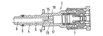
図1は、連結器2とパイプ3を有する加熱可能な流体線1を示す。パイプは柔軟である。これは押し出しプラスチックまたはホース材料から作られる。ホースは以下で語句「パイプ」に含まれる。
FIG. 1 shows a
パイプ3は連結器のパイプ接続4上で押され、Oリング5で密封される。パイプ接続4は、その外側に松の木の輪郭を有する。もし必要なら、パイプ3は、締め付け要素例えばホースクランプまたは類似物の助けによってパイプ接続4上に保持される。
The
直通の管6は、パイプ接続4を通して定められ、直通の管6は直線の手法で連結器全体を通過して走り、図2で見られるように、接続形状7にまで導かれる。接続形状7で連結器2は他の線、タンクまたは組み立て品のパイプ連結器に装着される。接続形状7の正確な形状は、現在の場合で無関係である。しかしながら、連結器2とパイプ接続間の接続は十分な強度と堅さを持って実装されるべきである。
A
破線によって示された加熱器8はパイプ3の自由断面の中に配置される。現在の場合で加熱器8は柔軟な加熱器棒として実装され、少なくとも1つの熱伝導体を有し、押し出しプラスチック材料の中に実装される。好ましくは、2つの熱伝導体が提供され、連結器2からある距離でお互いに1つの端で接続され、その結果、電気供給が加熱器8の1つの端でのみ必要となる。加熱器8は柔軟で曲げることが可能であるが、一定の固有の剛性を有し、(加熱器8がその中に置かれた)パイプ3がパイプ接続4上で押されたとき、加熱器8はパイプ接続4の中、直通の管6内に押されることができる。
The
加熱器8は、接続形状7の助けで達成された接続と干渉しないため、これが接続形状7に到達する前に連結器2から離れる。このため、連結器2は加熱器出口管9を有し、この縦方向の軸10は、直通の管6の縦方向の軸11と角度αである。角度αは0°より大きく、好ましくは20°から80°の範囲である。
Since the
加熱器出口管9は接続12の中に配置され、直通の管6の縦方向の軸11と角度αに向いている。Oリング13が接続12の中に提供される。Oリング13は加熱器8を密封の手法で支え、加熱器出口管から流体が漏れることを妨げる。Oリング13は、接続12の中に配置されたプラグ14の助けで加熱器出口管9の中に保持される。しかしながら、プラグ14は所定の場所でのみOリングを保持する。したがって、プラグ14はOリング13を圧縮しない。
The
上記で説明されたように、加熱器8は一定の固有の剛性を持つ。したがって、補助の道具は加熱器8をそらすために必要ない。加熱器8の先端は直通の管6を通して縦方向の軸11に沿って本質的に導かれ、加熱器8は加熱器出口管9を通して出て行く。この端で傾斜要素15は、直通の管6内に配置され、傾斜要素は特に図2で見える。傾斜要素15は連結器2とひとつなぎに実装される。連結器2が射出成形部分として実装された場合、傾斜要素15は射出成形の間に直接製造される。
As explained above, the
傾斜要素15は案内表面16を有し、これは曲がっている。つまり、ねじれがない手法で実装される。案内表面16は直通の管6の「底面」、つまり加熱器出口管9の反対に横たわる側から、加熱器出口管9まで伸び、加熱器出口管9の壁に連続する。加熱器8の先端は、段、ねじれ、溝または類似物によってじゃまされることなく案内表面16に沿って滑ることが可能である。加熱器8が直通の管6の中パイプ接続4を通過して導かれたとき、先端は傾斜要素15の案内表面16によってそらされ、自動的に加熱器出口管9に達する。
The tilting
図1による部分図の平面、つまり、直通の管6の縦方向の軸11と加熱器出口管9の縦方向の軸10によって広がる平面内で、傾斜要素15は完全に直通の管6を塞ぐ。図1参照。傾斜要素15は、したがって連結器2の筐体17に、案内表面16の両端で接続される。傾斜要素15が、加熱器8の先端によって力が働くときに傾く危険性はない。しかしながら、特に図2の中で見られるように、傾斜要素15は完全に直通の管6を塞がない。実際、図1に示された平面と横では、2つの流れ自由断面18、19が残り、動作中、流体が流れ続けることができる。傾斜要素15はいくらか直通の管6の自由断面を減少させる。しかし、まだ流体の流れのための自由な断面を十分に残す。
In the plane of the partial view according to FIG. 1, that is to say in the plane extended by the
2つの流れ断面18、19が加熱器8の直径より小さい幅を有することが認識できる。したがって、任意の場合で加熱器8が連結器2の中に挿入されたとき、加熱器8が加熱器出口管9の方向に案内表面16によってそらされることが確実になる。他方、傾斜要素15は、傾斜要素15の領域内で直通の管6の最も大きい幅の50%より大きくないことに対応する幅を有する。
It can be seen that the two
加熱器8が円形の断面、したがって実際の直径を有していない場合、流れ断面18、19の幅方向で加熱器8の幅は、流れ断面18、19の幅より大きい、この結果、この場合、連結器2内への挿入の間、加熱器8が傾斜要素15によってそらされることは確実に達成される。
If the
この型の連結器2を有する加熱可能な流体線1の製造は、設計で比較的簡単である。加熱器8を有するパイプ3が、事前に組み立て必要であり、加熱器8は所定の長さだけパイプ3から突き出る。したがって、パイプ3がパイプ接続4上で押される前に、加熱器8はすでにパイプ接続4の内部で直通の管6に到達する。さらにパイプ接続4上でパイプ3を押すため、パイプ3と加熱器8が一緒に動かされた場合、加熱器8の先端は傾斜要素15上で案内表面16によってそらされ、この先端は加熱器出口管9に到達し、連結器2から出ることが可能になる。
The manufacture of a
もちろん、連結器2の中に独立に加熱器8を最初に挿入し、加熱器8上にパイプ3を導き、パイプ接続4上でそれを押すことも可能である。
Of course, it is also possible to insert the
特に図1に見られるように、パイプ接続4の内部での直通の管6の流れ断面は、パイプ3の対応する流れ断面より、著しく小さい。例えば、もし、パイプ3の内直径が6mmであり、パイプ接続4の内部での直通の管6の内直径が4.75mmと仮定されると、4mmの直径の加熱器棒の使用で流れ断面は、結果的に15.7mm2のパイプ3の内部と5.1mm2の直通の管6内の流れ断面になる。パイプ接続4の内部での直通の管6の流れ断面は、したがって、パイプ3の内部の流れ管の面積の約32%を有する。
As can be seen in particular in FIG. 1, the flow cross section of the
厚さ0.375mmの環状の隙間は、加熱器棒8が中心に配置されたとき、パイプ接続4の内部周辺の壁と加熱器8の間の結果となる。この環状の隙間は、連結器を通して十分な量の尿素を通過させることを可能とするために十分である。しかしながら、多くの場合で、加熱器棒8は中心に位置しない。示された大きさにより、パイプ接続4と加熱器棒との間の隙間は、しかしながら、加熱器棒8がパイプ接続4の内壁を支えるとき、最大0.75mmの厚さを有する。
An annular gap with a thickness of 0.375 mm results between the
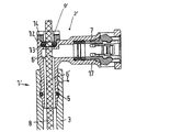
図3は連結器2’の修正された実施形態を示す。同一の要素と同じ機能を有する要素は、図1および図2と同じ参照番号で提供される。 FIG. 3 shows a modified embodiment of the coupler 2 '. Elements having the same function as the same elements are provided with the same reference numerals as in FIGS.
図1および図2による実施形態で、直通の管6は直線に走る(この型の連結器は「0°連結器」と言及される)。一方、図3による連結器2’を有する直通の管6’は90°の方向の変化を有する。この型の連結器2’は、「90°連結器」と言及される。
In the embodiment according to FIGS. 1 and 2, the
加熱器棒8がその長さの一部で直通の管6’を満たし、直通の管6’内部の流れ断面がパイプ3内部の流れ管断面よりもっと小さいことがここで認識できる。加熱器棒8は直線で、連結器2’を通して導かれる。つまり加熱器出口管9’は直線でパイプ接続4に連続する。
It can now be seen that the
加熱器棒8によって直接熱されない体積は、図1および図2による連結器2の体積に本質的に相当する。
The volume not directly heated by the
上記の例は、単に例示の目的のために提示されたものであり、本発明の制限として構成されるものではないことに注意すべきである。本発明は例示的な実施形態を参照し記載されたが、ここで用いられた言葉は、制限の言葉ではなく、記載と例示の言葉と理解すべきである。添付の請求項の範囲内で、本発明の範囲と概念から、その態様を逸脱することなく、ここで述べられたようにおよび補正によって、変形は可能である。本発明は、特定の手段、材料および形態に関して、ここで記載されたが、本発明は、ここで開示された特別なものに制限されない。むしろ、本発明は、添付された請求項の範囲内で機能的に同等な構成、方法および用途に拡張される。 It should be noted that the above examples are presented for illustrative purposes only and are not to be construed as limitations of the invention. Although the present invention has been described with reference to exemplary embodiments, it is to be understood that the language used herein is a description and an exemplary language, rather than a limiting word. Within the scope of the appended claims, variations and modifications may be made from the scope and concept of the invention as described herein and through amendments without departing from the scope thereof. Although the invention has been described herein with reference to specific means, materials and forms, the invention is not limited to the specifics disclosed herein. Rather, the invention extends to functionally equivalent structures, methods and uses within the scope of the appended claims.
1 流体線
2、2’ 連結器
3 パイプ
4 パイプ接続
5 Oリング
6、6’ 直通の管
7 接続形状
8 加熱器
9、9’ 加熱器出口管
10 縦方向の軸
11 縦方向の軸
12 接続
13 Oリング
14 プラグ
15 傾斜要素
16 案内表面
17 筐体
18、19 流れ断面
DESCRIPTION OF
Claims (20)
前記パイプ(3)の1つの端に配置されたパイプ接続(4)を有する連結器(2)と、
前記連結器(2)を通る直通の管(6)と、前記パイプ接続(4)は前記直通の管(6)の一部を取り囲み、
前記パイプ(3)の少なくとも一部および前記連結器(2)の少なくとも一部を加熱するため、前記パイプ(3)と前記連結器(2)の中に構成されおよび配置された加熱器(8)と、
を備え、すくなくとも、この長さの一部で前記直通の管(6)の流れ断面は、前記パイプ(3)の流れ断面の60%より大きくない、流体線(1)。 Pipe (3),
A coupler (2) having a pipe connection (4) arranged at one end of the pipe (3);
A direct pipe (6) through the coupler (2) and the pipe connection (4) surrounds a part of the direct pipe (6);
A heater (8) constructed and arranged in the pipe (3) and the coupler (2) for heating at least a part of the pipe (3) and at least a part of the coupler (2). )When,
The fluid line (1), wherein at least part of this length, the flow cross section of the direct pipe (6) is not greater than 60% of the flow cross section of the pipe (3).
前記直通の管(6)と0°と異なる角度を形成する加熱器出口管(9)と、
前記直通の管(6)の中に配置された案内表面(16)を有する傾斜要素(15)と、
をさらに備え、前記案内表面(16)は、前記直通の管(6)から前記加熱器出口管(9)を示し、前記パイプ接続(4)の他の側で前記直通の管(6)の断面を減少する請求項3の流体線。 The connector (2)
A heater outlet pipe (9) forming an angle different from 0 ° with said direct pipe (6);
A tilting element (15) having a guide surface (16) disposed in the straight pipe (6);
The guide surface (16) shows the heater outlet pipe (9) from the straight pipe (6) and the other side of the pipe connection (4) of the straight pipe (6). 4. The fluid line of claim 3, wherein the cross section is reduced.
前記パイプ直径、前記直通の管の内部直径、前記加熱器直径と前記加熱器幅の1つの少なくとも1つを選択すること、少なくともその長さの一部で前記直通の管(6)の流れ断面は、前記パイプ(3)の流れ断面の60%より大きくなく、
前記直通の管(6)の中に前記加熱器(8)を挿入すること、
前記パイプ接続(4)に前記パイプ(3)を取り付けること、
を備える方法。 A pipe (3), a coupler (2) having a pipe connection (4) disposed at one end of the pipe (3), a direct pipe (6) passing through the coupler (2), and A pipe connection (4) surrounds a part of the direct pipe (6) and is configured and arranged to heat at least a part of the pipe (3) and at least a part of the coupler (8). The pipe (3) has a pipe diameter, the direct pipe (6) has an internal diameter, and the heater (8) has a heater diameter and a heater. Has one of the widths,
Selecting at least one of the pipe diameter, the internal diameter of the direct pipe, the heater diameter and the heater width, at least part of its length, the flow cross section of the direct pipe (6) Is not greater than 60% of the flow cross section of the pipe (3),
Inserting the heater (8) into the direct pipe (6);
Attaching the pipe (3) to the pipe connection (4);
A method comprising:
前記直通の管(6)と0°と異なる角度を形成する加熱器出口管(9)と、
前記直通の管(6)に配置された案内表面(16)を有する傾斜要素(15)をさらに備え、
前記案内表面(16)は、前記直通の管(6)から前記加熱器出口管(9)を示し、前記パイプ接続(4)の他の側で前記直通の管(6)の断面を減少する請求項13の方法。 The connector (2)
A heater outlet pipe (9) forming an angle different from 0 ° with said direct pipe (6);
Further comprising a tilting element (15) having a guide surface (16) arranged in said straight pipe (6);
The guide surface (16) shows the heater outlet pipe (9) from the straight pipe (6) and reduces the cross section of the straight pipe (6) on the other side of the pipe connection (4). The method of claim 13.
Applications Claiming Priority (2)
| Application Number | Priority Date | Filing Date | Title |
|---|---|---|---|
| DE102011102148.9 | 2011-05-20 | ||
| DE201110102148 DE102011102148A1 (en) | 2011-05-20 | 2011-05-20 | fluid line |
Publications (2)
| Publication Number | Publication Date |
|---|---|
| JP2012241901A true JP2012241901A (en) | 2012-12-10 |
| JP5555280B2 JP5555280B2 (en) | 2014-07-23 |
Family
ID=45877936
Family Applications (1)
| Application Number | Title | Priority Date | Filing Date |
|---|---|---|---|
| JP2012112358A Active JP5555280B2 (en) | 2011-05-20 | 2012-05-16 | Fluid line |
Country Status (8)
| Country | Link |
|---|---|
| US (1) | US9671053B2 (en) |
| EP (1) | EP2527703B1 (en) |
| JP (1) | JP5555280B2 (en) |
| CN (1) | CN102788221B (en) |
| DE (1) | DE102011102148A1 (en) |
| ES (1) | ES2518191T3 (en) |
| RS (1) | RS53663B1 (en) |
| RU (1) | RU2531491C2 (en) |
Cited By (2)
| Publication number | Priority date | Publication date | Assignee | Title |
|---|---|---|---|---|
| KR20170021293A (en) * | 2014-06-17 | 2017-02-27 | 노르마 저머니 게엠베하 | Heatable fluid line |
| JP2017525882A (en) * | 2014-06-17 | 2017-09-07 | ノーマ ジャーマニー ゲーエムベーハー | Fluid line |
Families Citing this family (13)
| Publication number | Priority date | Publication date | Assignee | Title |
|---|---|---|---|---|
| DE102008022663B4 (en) | 2008-05-07 | 2012-10-31 | Schauenburg Hose Technology Gmbh | Stretch hose |
| US9505164B2 (en) | 2009-12-30 | 2016-11-29 | Schauenburg Technology Se | Tapered helically reinforced hose and its manufacture |
| US9964238B2 (en) | 2009-01-15 | 2018-05-08 | Globalmed, Inc. | Stretch hose and hose production method |
| DE102013103534B4 (en) * | 2013-04-09 | 2025-05-08 | Voss Automotive Gmbh | "Plug-in connection part for a cable connector, in particular for a pre-assembled media cable" |
| DE102014113793A1 (en) * | 2014-02-07 | 2015-08-13 | Halla Visteon Climate Control Corporation | Refrigerant accumulator, in particular for motor vehicle refrigerant circuits |
| EP3211190B1 (en) * | 2016-02-23 | 2019-04-17 | TI Automotive (Fuldabrück) GmbH | Connector assembly with at least one connector and at least one fluid line |
| US10396500B2 (en) | 2016-08-31 | 2019-08-27 | Norma U.S. Holding Llc | Electrically conductive conduit assembly |
| US11014105B2 (en) * | 2016-10-15 | 2021-05-25 | Akurate Dynamics, Llc | Multi-segment heated hose having segment-specific heating means |
| WO2018138581A1 (en) | 2017-01-30 | 2018-08-02 | Globalmed, Inc. | Heated respiratory hose assembly |
| CN107314184A (en) * | 2017-06-20 | 2017-11-03 | 临海市永恒汽配科技有限公司 | The joint and heating tube of heating tube |
| US10947938B2 (en) | 2017-06-21 | 2021-03-16 | Steere Enterprises, Inc. | Air duct assembly with a secured seal |
| US10190716B1 (en) * | 2018-09-11 | 2019-01-29 | Akurate Dynamics, Llc | Heated hose with improved power feedthrough |
| US12404963B2 (en) * | 2022-09-02 | 2025-09-02 | Ruben Sandoval | Water pipe winterizing assembly |
Citations (4)
| Publication number | Priority date | Publication date | Assignee | Title |
|---|---|---|---|---|
| JPS582463A (en) * | 1981-06-15 | 1983-01-08 | レイケム・コ−ポレイシヨン | Fuel supply path and heating assembly |
| JPH0579593A (en) * | 1990-08-28 | 1993-03-30 | Petroleo Brasileiro Sa | Electrical heating method for pipeline |
| EP1070642A2 (en) * | 1999-07-22 | 2001-01-24 | REHAU AG + Co | Heating device for a windschield washer system |
| JP2009002424A (en) * | 2007-06-21 | 2009-01-08 | Nitta Moore Co | Piping structure of heating and heat-retention pipe |
Family Cites Families (21)
| Publication number | Priority date | Publication date | Assignee | Title |
|---|---|---|---|---|
| US1905733A (en) | 1932-03-18 | 1933-04-25 | Texas Co | Flow divider |
| US2141797A (en) | 1937-03-26 | 1938-12-27 | Minella Angelo | Fitting |
| US3894302A (en) | 1972-03-08 | 1975-07-15 | Tyler Pipe Ind Inc | Self-venting fitting |
| JPS60180982A (en) | 1984-02-25 | 1985-09-14 | 秦 欣哉 | Manufacture of feed or fertilizer from animals, fishes and shells |
| DE3414284A1 (en) * | 1984-04-14 | 1985-10-31 | Heraeus-Wittmann Gmbh, 6450 Hanau | Electrical heating element for pipelines, especially for long pipelines |
| SU1571352A1 (en) * | 1988-03-16 | 1990-06-15 | Грозненский Нефтяной Институт Им.Акад.М.Д.Миллионщикова | Heated pipeline |
| US6944394B2 (en) * | 2002-01-22 | 2005-09-13 | Watlow Electric Manufacturing Company | Rapid response electric heat exchanger |
| US7033113B2 (en) * | 2003-05-01 | 2006-04-25 | Shell Oil Company | Mid-line connector and method for pipe-in-pipe electrical heating |
| DE10325517A1 (en) | 2003-06-05 | 2004-12-23 | Hew-Kabel/Cdt Gmbh & Co. Kg | Electric heating cable or heating tape |
| US20050167134A1 (en) * | 2004-02-02 | 2005-08-04 | Philippe Charron | Heating cable substantially free from electromagnetic field |
| SE528060C2 (en) | 2004-02-25 | 2006-08-22 | Volvo Lastvagnar Ab | Electrically heated cabling |
| SE529417C2 (en) | 2005-12-22 | 2007-08-07 | Volvo Lastvagnar Ab | Wiring harness for a vehicle |
| RU2300043C1 (en) * | 2006-02-13 | 2007-05-27 | Общество с ограниченной ответственностью "Промтех-НН" | Pipeline heater |
| RU55082U1 (en) * | 2006-02-26 | 2006-07-27 | Закрытое акционерное общество "Сибпромкомплект" | PIPELINE |
| RU59192U1 (en) * | 2006-03-10 | 2006-12-10 | Открытое акционерное общество "Научно-производственное объединение по исследованию и проектированию энергетического оборудования им. И.И. Ползунова" (ОАО "НПО ЦКТИ") | PIPELINE FOR TRANSPORTATION OF WATER |
| FR2905161B1 (en) | 2006-08-25 | 2012-04-20 | Inergy Automotive Systems Res | CONNECTION WITH INTEGRATED HEATING ELEMENT. |
| DE202007009588U1 (en) | 2007-04-26 | 2008-09-04 | Voss Automotive Gmbh | Cable connector for media cables |
| JP4823980B2 (en) * | 2007-07-30 | 2011-11-24 | ニッタ株式会社 | Equipment with heating and heat insulation tubes |
| FR2924786A1 (en) | 2007-12-11 | 2009-06-12 | Coutier Moulage Gen Ind | Fluid e.g. oil, transporting heating conduit for motor vehicle, has electrical connector provided near coupling fitting for supplying electrical energy, and transferring unit to transfer heating power towards coupling fitting zone |
| DE202008003270U1 (en) | 2008-03-06 | 2009-10-01 | Rehau Ag + Co | Assembly for receiving and heating a urea-water solution |
| CN201680154U (en) | 2010-02-08 | 2010-12-22 | 工德股份有限公司 | Fluid pipeline heating device |
-
2011
- 2011-05-20 DE DE201110102148 patent/DE102011102148A1/en not_active Withdrawn
-
2012
- 2012-02-29 RS RS20140637A patent/RS53663B1/en unknown
- 2012-02-29 ES ES12001339.6T patent/ES2518191T3/en active Active
- 2012-02-29 EP EP20120001339 patent/EP2527703B1/en active Active
- 2012-05-01 US US13/461,293 patent/US9671053B2/en active Active
- 2012-05-09 CN CN201210141654.7A patent/CN102788221B/en active Active
- 2012-05-16 JP JP2012112358A patent/JP5555280B2/en active Active
- 2012-05-18 RU RU2012120425/06A patent/RU2531491C2/en active
Patent Citations (4)
| Publication number | Priority date | Publication date | Assignee | Title |
|---|---|---|---|---|
| JPS582463A (en) * | 1981-06-15 | 1983-01-08 | レイケム・コ−ポレイシヨン | Fuel supply path and heating assembly |
| JPH0579593A (en) * | 1990-08-28 | 1993-03-30 | Petroleo Brasileiro Sa | Electrical heating method for pipeline |
| EP1070642A2 (en) * | 1999-07-22 | 2001-01-24 | REHAU AG + Co | Heating device for a windschield washer system |
| JP2009002424A (en) * | 2007-06-21 | 2009-01-08 | Nitta Moore Co | Piping structure of heating and heat-retention pipe |
Cited By (6)
| Publication number | Priority date | Publication date | Assignee | Title |
|---|---|---|---|---|
| KR20170021293A (en) * | 2014-06-17 | 2017-02-27 | 노르마 저머니 게엠베하 | Heatable fluid line |
| JP2017524874A (en) * | 2014-06-17 | 2017-08-31 | ノーマ ジャーマニー ゲーエムベーハー | Heatable fluid line |
| JP2017525882A (en) * | 2014-06-17 | 2017-09-07 | ノーマ ジャーマニー ゲーエムベーハー | Fluid line |
| US10371302B2 (en) | 2014-06-17 | 2019-08-06 | Norma Germany Gmbh | Heatable fluid line |
| KR102031624B1 (en) * | 2014-06-17 | 2019-10-14 | 노르마 저머니 게엠베하 | Heatable fluid line |
| US10539262B2 (en) | 2014-06-17 | 2020-01-21 | Norma Germany Gmbh | Fluid line |
Also Published As
| Publication number | Publication date |
|---|---|
| EP2527703A1 (en) | 2012-11-28 |
| CN102788221A (en) | 2012-11-21 |
| US20120291881A1 (en) | 2012-11-22 |
| EP2527703B1 (en) | 2014-10-08 |
| CN102788221B (en) | 2014-10-01 |
| RU2531491C2 (en) | 2014-10-20 |
| RS53663B1 (en) | 2015-04-30 |
| ES2518191T3 (en) | 2014-11-04 |
| JP5555280B2 (en) | 2014-07-23 |
| RU2012120425A (en) | 2013-12-10 |
| DE102011102148A1 (en) | 2012-11-22 |
| US9671053B2 (en) | 2017-06-06 |
Similar Documents
| Publication | Publication Date | Title |
|---|---|---|
| JP5555280B2 (en) | Fluid line | |
| KR101372539B1 (en) | Connector for a heatable fluid line and heatable fluid line | |
| KR101464575B1 (en) | Fluid line | |
| CN103998845B (en) | At least partially heatable pipe connector for a heatable media pipe and assembled media pipe with the pipe connector | |
| ES2375749T5 (en) | Pipe connector for media pipes | |
| CN103672281B (en) | Push-fit connector | |
| JP5185679B2 (en) | Tube for liquid transfer | |
| US20100064670A1 (en) | Reductant Supply System for a Waste Gas Cleaning Catalyst and a Heating Unit Therefor | |
| JP2018151068A (en) | Connection unit | |
| CN104864217A (en) | Connector For A Heatable Fluid Conduit And Heatable Fluid Conduit | |
| CN107101065A (en) | Connector assembly including at least one connector He at least one medium pipeline | |
| JP5059631B2 (en) | Heating and heat insulation cover for pipe fittings | |
| CN106662282B (en) | Heatable fluid line | |
| KR20120130048A (en) | Fluid line | |
| CN205424249U (en) | Electrically heatable medium pipes | |
| CN204104153U (en) | Electric heating tube component | |
| JP2020513509A (en) | Plug connector | |
| KR20190127961A (en) | Heating piping equipped with a plug and a method of operating the piping | |
| KR200332323Y1 (en) | Connection pad of spiral pipe | |
| CN118775014A (en) | Pipeline device for exhaust gas treatment equipment, exhaust gas treatment equipment and motor vehicle |
Legal Events
| Date | Code | Title | Description |
|---|---|---|---|
| RD04 | Notification of resignation of power of attorney |
Free format text: JAPANESE INTERMEDIATE CODE: A7424 Effective date: 20130311 |
|
| RD02 | Notification of acceptance of power of attorney |
Free format text: JAPANESE INTERMEDIATE CODE: A7422 Effective date: 20130319 |
|
| RD04 | Notification of resignation of power of attorney |
Free format text: JAPANESE INTERMEDIATE CODE: A7424 Effective date: 20130409 |
|
| A977 | Report on retrieval |
Free format text: JAPANESE INTERMEDIATE CODE: A971007 Effective date: 20130731 |
|
| A131 | Notification of reasons for refusal |
Free format text: JAPANESE INTERMEDIATE CODE: A131 Effective date: 20130827 |
|
| TRDD | Decision of grant or rejection written | ||
| A01 | Written decision to grant a patent or to grant a registration (utility model) |
Free format text: JAPANESE INTERMEDIATE CODE: A01 Effective date: 20140430 |
|
| A61 | First payment of annual fees (during grant procedure) |
Free format text: JAPANESE INTERMEDIATE CODE: A61 Effective date: 20140530 |
|
| R150 | Certificate of patent or registration of utility model |
Ref document number: 5555280 Country of ref document: JP Free format text: JAPANESE INTERMEDIATE CODE: R150 |
|
| R250 | Receipt of annual fees |
Free format text: JAPANESE INTERMEDIATE CODE: R250 |
|
| R250 | Receipt of annual fees |
Free format text: JAPANESE INTERMEDIATE CODE: R250 |
|
| R250 | Receipt of annual fees |
Free format text: JAPANESE INTERMEDIATE CODE: R250 |
|
| R250 | Receipt of annual fees |
Free format text: JAPANESE INTERMEDIATE CODE: R250 |
|
| R250 | Receipt of annual fees |
Free format text: JAPANESE INTERMEDIATE CODE: R250 |
|
| R250 | Receipt of annual fees |
Free format text: JAPANESE INTERMEDIATE CODE: R250 |
|
| R250 | Receipt of annual fees |
Free format text: JAPANESE INTERMEDIATE CODE: R250 |
|
| R250 | Receipt of annual fees |
Free format text: JAPANESE INTERMEDIATE CODE: R250 |
|
| R250 | Receipt of annual fees |
Free format text: JAPANESE INTERMEDIATE CODE: R250 |