JP2012242538A - Projector - Google Patents
Projector Download PDFInfo
- Publication number
- JP2012242538A JP2012242538A JP2011111256A JP2011111256A JP2012242538A JP 2012242538 A JP2012242538 A JP 2012242538A JP 2011111256 A JP2011111256 A JP 2011111256A JP 2011111256 A JP2011111256 A JP 2011111256A JP 2012242538 A JP2012242538 A JP 2012242538A
- Authority
- JP
- Japan
- Prior art keywords
- air
- air inlet
- projector
- blades
- air filter
- Prior art date
- Legal status (The legal status is an assumption and is not a legal conclusion. Google has not performed a legal analysis and makes no representation as to the accuracy of the status listed.)
- Withdrawn
Links
- 238000001816 cooling Methods 0.000 claims abstract description 29
- 239000000428 dust Substances 0.000 claims abstract description 9
- 238000011144 upstream manufacturing Methods 0.000 claims abstract description 5
- 230000002349 favourable effect Effects 0.000 abstract description 4
- 230000003287 optical effect Effects 0.000 description 4
- 238000007599 discharging Methods 0.000 description 3
- 239000003086 colorant Substances 0.000 description 2
- 238000010586 diagram Methods 0.000 description 1
- 230000000694 effects Effects 0.000 description 1
- 230000005611 electricity Effects 0.000 description 1
- 239000004973 liquid crystal related substance Substances 0.000 description 1
- 238000012986 modification Methods 0.000 description 1
- 230000004048 modification Effects 0.000 description 1
- 229920005594 polymer fiber Polymers 0.000 description 1
- 230000003068 static effect Effects 0.000 description 1
Images


Landscapes
- Projection Apparatus (AREA)
Abstract
【課題】設計の自由度を低下させることなく、外観上好ましい構成を実現できるプロジェクターを提供する。
【解決手段】プロジェクター1は、吸気口21Bを有する外装筐体2と、外装筐体2内部に配設され、吸気口21Bを介して外装筐体2外部の空気を外装筐体2内部に導入する冷却ファンと、吸気口21Bから冷却ファンに至る空気の流路中に配設され、吸気口21Bを介して導入された空気に含まれる塵埃を捕捉するエアフィルター6と、吸気口21B及びエアフィルター6間の流路中に配設され、複数の羽根板82を有するルーバー8とを備える。複数の羽根板82は、流路の上流側から見て、互いに重なるように形成されている。
【選択図】図3A projector capable of realizing a configuration that is favorable in appearance without reducing the degree of freedom in design is provided.
A projector includes an exterior housing having an air inlet and a housing, and introduces air outside the housing from the air through the air inlet. A cooling fan, an air filter 6 that is disposed in an air flow path extending from the air inlet 21B to the cooling fan and captures dust contained in the air introduced through the air inlet 21B, the air inlet 21B, and the air And a louver 8 having a plurality of blades 82 disposed in the flow path between the filters 6. The plurality of blades 82 are formed so as to overlap each other when viewed from the upstream side of the flow path.
[Selection] Figure 3
Description
本発明は、プロジェクターに関する。 The present invention relates to a projector.
従来、プロジェクターにおいて、外装筐体内部に配設される冷却対象に空気を送風するために、外装筐体に形成された吸気口を介して外装筐体外部の空気を外装筐体内部に導入する冷却構造を備えた構成が知られている(例えば、特許文献1参照)。
特許文献1に記載の冷却構造は、吸気口を介して外装筐体外部の空気を外装筐体内部に導入する吸気ファンの他、吸気口から吸気ファンに至る空気の流路中に配設されるエアフィルターを備える。
そして、エアフィルターを上記位置に配設することで、吸気口から外装筐体内部に導入される空気に含まれる塵埃をエアフィルターにて捕捉し、外装筐体内部に配設される部材に塵埃が付着することを防止している。
2. Description of the Related Art Conventionally, in a projector, air outside an exterior casing is introduced into the exterior casing via an air inlet formed in the exterior casing in order to blow air to a cooling target disposed inside the exterior casing. A configuration having a cooling structure is known (see, for example, Patent Document 1).
The cooling structure described in
Then, by disposing the air filter at the above position, dust contained in the air introduced into the exterior casing from the air inlet is captured by the air filter, and the dust disposed on the member disposed inside the exterior casing. Is prevented from adhering.
しかしながら、特許文献1に記載の冷却構造では、吸気口を介して外装筐体外部からエアフィルターが視認され易い構造となっており、プロジェクターの外観が好ましいものとは言い難いものである。
特に、外装筐体の色と、エアフィルターの色とが異なる場合、例えば、外装筐体の色が黒で、エアフィルターの色が白の場合には、外装筐体外部からエアフィルターが視認され易いものとなる。
そして、プロジェクターの外観を好ましいものとするためには、外装筐体の色をエアフィルターの色に合わせる必要があり、設計の自由度が低下してしまう、という問題がある。
However, the cooling structure described in
In particular, when the color of the outer casing and the color of the air filter are different, for example, when the color of the outer casing is black and the color of the air filter is white, the air filter is visible from the outside of the outer casing. It will be easy.
In order to make the appearance of the projector favorable, there is a problem that the color of the exterior housing needs to be matched with the color of the air filter, and the degree of freedom in design is reduced.
本発明の目的は、設計の自由度を低下させることなく、外観上好ましい構成を実現できるプロジェクターを提供することにある。 An object of the present invention is to provide a projector capable of realizing a configuration that is favorable in appearance without reducing the degree of freedom in design.
本発明のプロジェクターは、吸気口を有する外装筐体と、前記外装筐体内部に配設され、前記吸気口を介して前記外装筐体外部の空気を前記外装筐体内部に導入する冷却ファンと、前記吸気口から前記冷却ファンに至る空気の流路中に配設され、前記吸気口を介して導入された空気に含まれる塵埃を捕捉するエアフィルターと、前記吸気口及び前記エアフィルター間の前記流路中に配設され、複数の羽根板を有するルーバーとを備え、前記複数の羽根板は、前記流路の上流側から見て、互いに重なるように形成されていることを特徴とする。 The projector of the present invention includes an exterior housing having an air inlet, a cooling fan that is disposed inside the exterior housing and introduces air outside the exterior housing into the exterior housing through the air inlet. An air filter disposed in an air flow path from the air inlet to the cooling fan and capturing dust contained in the air introduced through the air inlet; and between the air inlet and the air filter And a louver having a plurality of blades disposed in the flow path, wherein the plurality of blades are formed to overlap each other when viewed from the upstream side of the flow path. .
本発明では、プロジェクターは、吸気口及びエアフィルター間に上述したルーバーが配設されている。
このことにより、ルーバーを構成する複数の羽根板が外装筐体内部の目隠しとなり、外装筐体外部からエアフィルターが視認され難い構造を実現できる。すなわち、プロジェクターの外観を好ましいものとすることができる。
また、プロジェクターの外観を好ましいものとするために外装筐体の色をエアフィルターの色に合わせる必要がなく、外装筐体を種々の色に設定でき、設計の自由度を低下させることがない。
In the present invention, the projector has the louver described above disposed between the air inlet and the air filter.
As a result, a plurality of blades constituting the louver are blindfolded inside the outer casing, and a structure in which the air filter is hardly visible from the outside of the outer casing can be realized. That is, the appearance of the projector can be made preferable.
Further, in order to make the appearance of the projector favorable, it is not necessary to match the color of the exterior housing to the color of the air filter, the exterior housing can be set in various colors, and the degree of design freedom is not reduced.
本発明のプロジェクターでは、前記複数の羽根板は、少なくとも一度、折れ曲がる形状を有していることが好ましい。
本発明では、複数の羽根板が少なくとも一度、折れ曲がる形状を有しているので、ルーバーに対する流路上流側の種々の位置から見ても、複数の羽根板によりエアフィルターが全く視認できない構造を実現できる。
In the projector according to the aspect of the invention, it is preferable that the plurality of blades have a shape that bends at least once.
In the present invention, since the plurality of blades are bent at least once, a structure in which the air filter cannot be visually recognized by the plurality of blades even when viewed from various positions on the upstream side of the flow path with respect to the louver is realized. it can.
本発明のプロジェクターでは、前記エアフィルターは、前記吸気口に対向するように配設されていることが好ましい。
ところで、外装筐体外部からエアフィルターが視認され難い構造として、吸気口から冷却ファンに向けて延びるダクトを長く設定する(吸気口からエアフィルターに至る空気の流路を長く設定する)、あるいは、吸気口に対向しないようにエアフィルターを配設することが考えられる。
しかしながら、上記のように構成した場合には、冷却ファンによる空気の吸気効率が悪くなり、吸気口を介して外装筐体内部に導入した空気により冷却対象を効率的に冷却することが難しい。
本発明では、エアフィルターを吸気口に対向するように配設しても、上述した複数の羽根板が外装筐体内部の目隠しとなるため、冷却ファンによる空気の吸気効率を良好に維持でき、吸気口を介して外装筐体内部に導入した空気により冷却対象を効率的に冷却できる。
In the projector according to the aspect of the invention, it is preferable that the air filter is disposed so as to face the intake port.
By the way, as a structure in which the air filter is difficult to be visually recognized from the outside of the exterior housing, a long duct extending from the air inlet to the cooling fan is set (the air flow path from the air inlet to the air filter is set long), or It is conceivable to arrange an air filter so as not to face the intake port.
However, when configured as described above, the efficiency of air intake by the cooling fan is deteriorated, and it is difficult to efficiently cool the object to be cooled by the air introduced into the exterior casing through the air inlet.
In the present invention, even if the air filter is disposed so as to face the intake port, the plurality of vanes described above are blinded inside the outer casing, so that the air intake efficiency by the cooling fan can be maintained well, The cooling target can be efficiently cooled by the air introduced into the exterior casing through the air inlet.
以下、本発明の実施の一形態を図面に基づいて説明する。
〔プロジェクターの構成〕
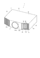
図1は、本実施形態におけるプロジェクター1の外観構成を模式的に示す斜視図である。
なお、以下では、説明の便宜上、後述する投射レンズ3Aが配置される側を「前面」とし、その反対側を「背面」とする。
プロジェクター1は、画像を投射してスクリーン(図示略)上に投影画像を表示する。
このプロジェクター1は、図1に示すように、外装を構成する外装筐体2と、光学ユニット3と、吸気装置4(図2参照)等を備える。
Hereinafter, an embodiment of the present invention will be described with reference to the drawings.
[Configuration of projector]
FIG. 1 is a perspective view schematically showing an external configuration of a
In the following, for convenience of explanation, a side on which a
The
As shown in FIG. 1, the
〔外装筐体の構成〕
外装筐体2は、図1に示すように、前面側に位置する前壁部21と、背面側に位置する後壁部22と、前面側から見て左側及び右側にそれぞれ位置する左壁部23及び右壁部24と、上側及び下側にそれぞれ位置する天面部25及び底面部26とを備え、略直方体形状を有する。
この外装筐体2において、前壁部21の略中央位置には、図1に示すように、投射レンズ3Aの一部を外部に露出させ、投射レンズ3Aを介して投射される画像を通過させるための開口部21Aが形成されている。
また、前壁部21において、開口部21Aに対して前面側から見て右側には、外装筐体2外部の空気を外装筐体2内部に取り込むための吸気口21Bが形成されている。
さらに、前壁部21において、開口部21Aに対して前面側から見て左側には、外装筐体2内部の空気を外装筐体2外部に排出するための排気口21Cが形成されている。
[Configuration of exterior casing]
As shown in FIG. 1, the
In this
Further, in the
Further, in the
〔光学ユニットの構成〕
光学ユニット3は、種々の一般的なプロジェクターで利用されているため、具体的な図示及び説明は省略するが、光源ランプを有する光源装置と、光源装置から出射された光束を変調する液晶パネル等の光変調装置と、光変調装置にて変調された光束を投射する投射光学装置としての投射レンズ3A(図1)等を備える。
[Configuration of optical unit]
Since the
〔吸気装置の構成〕
図2は、吸気装置4の構成を模式的に示す図である。具体的に、図2は、天面部25や底面部26に略平行となる平面にて吸気装置4を切断した断面を上方から見た図である。
吸気装置4は、吸気口21Bを介して外装筐体2外部の空気を導入する。
この吸気装置4は、図2に示すように、冷却ファン5と、エアフィルター6と、ファン筐体7と、ルーバー8とを備える。
冷却ファン5は、図2に示すように、空気を吸入する吸入口51、及び空気を吐出する吐出口52を有し、吸入口51からファン回転軸Axに沿って空気を吸入し、吐出口52からファンの回転接線方向に吐出する、所謂シロッコファンで構成されている。
[Configuration of intake system]
FIG. 2 is a diagram schematically showing the configuration of the
The
As shown in FIG. 2, the
As shown in FIG. 2, the
エアフィルター6は、吸気口21Bから冷却ファン5に至る空気の流路中に配設され、吸気口21Bから導入された空気に含まれる塵埃を捕捉する。
このエアフィルター6は、図2に示すように、フィルター本体61と、支持枠62とを備える。
フィルター本体61は、塵埃を捕捉する部分であり、本実施形態では、静電フィルターで構成されている。
より具体的には、フィルター本体61は、静電気を帯電させた高分子繊維をプリーツ加工することにより、表面積を拡大させて塵埃の捕集効率を向上させている。
The
As shown in FIG. 2, the
The filter
More specifically, the filter
支持枠62は、ファン筐体7における後述する筐体本体71の内面に嵌合する略矩形枠形状を有し、枠状内部にてフィルター本体61を支持する。
なお、本実施形態では、エアフィルター6は、ファン筐体7により、吸気口21Bに対向するように配設されるとともに、当該エアフィルター6の中心位置C1が吸気口21Bの中心位置C2に対してずれるように配設されている(図3参照)。
また、エアフィルター6は、吸気口21Bの開口面積よりも大きい外形形状を有するように形成されている(図3参照)。
The
In the present embodiment, the
The
ファン筐体7は、冷却ファン5及びエアフィルター6が内部に収納されるとともに、ルーバー8と接続する部分である。
そして、ファン筐体7は、図2に示すように、筐体本体71と、接続部72とを備える。
筐体本体71は、前後方向(前面側から背面側への方向)に延び、前面側が開口した略直方体形状を有する。
この筐体本体71において、背面側の側壁の一部には、図2に示すように、筐体本体71内部の空気を筐体本体71外部に排出するための排出口711が形成されている。
そして、冷却ファン5は、図2に示すように、吸入口51が上方に向き、吐出口52が背面側に向いて排出口711に接続するように、筐体本体71の底面に取り付けられる。
また、エアフィルター6は、図2に示すように、筐体本体71における前面側の開口部分712に嵌合する。
The
And the fan housing |
The casing
As shown in FIG. 2, in the housing
As shown in FIG. 2, the cooling
Further, the
接続部72は、筐体本体71における開口部分712に接続する略筒形状を有する。
そして、接続部72は、図2に示すように、開口部分712との接続位置から、内部の流路面積を減少させながら、前面右側(ファン筐体7が外装筐体2内部に取り付けられた状態で、右壁部24側)に延びるように形成されている。
そして、ファン筐体7は、内部に配設されたエアフィルター6が吸気口21Bに対向し(図3参照)、接続部72が吸気口21Bに向けて延びるように外装筐体2内部に配設される。
The
Then, as shown in FIG. 2, the connecting
The
ルーバー8は、吸気口21Bに着脱自在に取り付けられる。すなわち、ルーバー8は、吸気口21Bから冷却ファン5に至る流路において、吸気口21B及びエアフィルター6間の流路中に配設される。そして、ルーバー8は、吸気口21Bに取り付けられた状態でファン筐体7の接続部72に接続し、吸気口21Bを介して導入される空気を接続部72に導く。
このルーバー8は、図1または図2に示すように、支持枠81と、複数の羽根板82とを備える。
支持枠81は、前面側から見て、略矩形枠状に形成されている。
複数の羽根板82は、支持枠81における上下の内壁間に架設され、左右方向に沿って所定のピッチで並設されている。
As shown in FIG. 1 or FIG. 2, the
The
The plurality of
図3は、吸気口21Bに取り付けられたルーバー8を前面側から見た図である。
具体的に、複数の羽根板82の少なくとも一部の羽根板82Aは、図2に示すように、前面側から背面左側(左壁部23側)に向けて延びる第1リブ82A1と、第1リブ82A1の背面側の端部に接続し、当該接続位置から、第1リブ82A1に略直交して、背面右側(右壁部24側)に向けて延びる第2リブ82A2とを備える。すなわち、羽根板82Aは、1度、折れ曲がる形状を有している。
そして、複数の羽根板82は、第1,第2リブ82A1,82A2の延出方向の長さや、前記ピッチ等を適宜調整することで、図3に示すように、前面側(吸気口21Bから冷却ファン5に至る空気の流路上流側)から見て、互いに重なるように形成されている。
なお、図3では前面側から見た状態を示しているが、複数の羽根板82は、第1リブ82A1の延出方向に沿う方向から見た場合であっても、第1リブ82A1に略直交して延出する第2リブ82A2同士が互いに重なるように形成されている。
FIG. 3 is a view of the
Specifically, as shown in FIG. 2, at least some of the
The plurality of
In addition, although the state seen from the front side is shown in FIG. 3, even if it is a case where it sees from the direction in alignment with the extending direction of 1st rib 82A1, the
そして、吸気装置4は、上述したように形成されていることにより、冷却ファン5の駆動により、外装筐体2外部の空気を以下に示すように内部に導くこととなる。
すなわち、外装筐体2外部の空気は、冷却ファン5の駆動により、図2に矢印で示すように、吸気口21Bを介して外装筐体2内部に導入される際、複数の羽根板82により整流されつつ、斜め方向からエアフィルター6に衝突する。
エアフィルター6に衝突した空気は、エアフィルター6にて塵埃が捕捉され、清浄化された後、冷却ファン5の吸入口51に吸入される。
そして、冷却ファン5に吸入された空気は、吐出口52を介して吐出され、排出口711を介してファン筐体7外部に排出され、図示しないダクトを介して、冷却対象に向けて導かれる。
Since the
That is, when the air outside the
The air colliding with the
Then, the air sucked into the cooling
上述した本実施形態によれば、以下の効果がある。
本実施形態では、プロジェクター1は、吸気口21B及びエアフィルター6間にルーバー8が配設されている。
このことにより、ルーバー8を構成する複数の羽根板82が外装筐体2内部の目隠しとなり、外装筐体2外部からエアフィルター6が視認され難い構造を実現できる。すなわち、プロジェクター1の外観を好ましいものとすることができる。
また、プロジェクター1の外観を好ましいものとするために外装筐体2の色をエアフィルター6の色に合わせる必要がなく、外装筐体2を種々の色に設定でき、設計の自由度を低下させることがない。
According to this embodiment described above, the following effects are obtained.
In the present embodiment, the
As a result, a plurality of
Further, in order to make the appearance of the
また、複数の羽根板82Aが一度、折れ曲がる形状を有しているので、ルーバー8に対する前面側の種々の位置から見ても、複数の羽根板82Aによりエアフィルター6が全く視認できない構造を実現できる。
さらに、エアフィルター6を吸気口21Bに対向するように配設しても、複数の羽根板82が外装筐体2内部の目隠しとなるため、冷却ファン5による空気の吸気効率を良好に維持でき、吸気口21Bを介して外装筐体2内部に導入した空気により冷却対象を効率的に冷却できる。
Further, since the plurality of
Furthermore, even if the
なお、本発明は前述の実施形態に限定されるものではなく、本発明の目的を達成できる範囲での変形、改良等は本発明に含まれるものである。
前記実施形態では、本発明に係る吸気ファンとしてシロッコファンを採用したが、これに限らない。例えば、冷却ファンとしては、ファン回転軸に沿って吸入及び吐出する軸流ファンや、ファン回転軸を中心として回転し、回転方向に対して後向きに曲がった複数の羽根が外周に一体化される羽根車を有するターボファンを採用しても構わない。
前記実施形態において、複数の羽根板82の形状は、前記実施形態で説明した形状に限らず、前面側から見た場合に複数の羽根板82が互いに重なる形状であれば、いずれの形状でも構わない。
前記実施形態では、フロント投射型のプロジェクターの例のみを挙げたが、本発明は、スクリーンを備え、当該スクリーンの裏面側から投射を行うリアタイプのプロジェクターにも適用可能である。
It should be noted that the present invention is not limited to the above-described embodiments, and modifications, improvements, and the like within the scope that can achieve the object of the present invention are included in the present invention.
In the embodiment, the sirocco fan is employed as the intake fan according to the present invention, but the present invention is not limited to this. For example, as a cooling fan, an axial fan that sucks and discharges along a fan rotation axis, and a plurality of blades that rotate about the fan rotation axis and are bent backward with respect to the rotation direction are integrated on the outer periphery. A turbo fan having an impeller may be adopted.
In the embodiment, the shape of the plurality of
In the above embodiment, only an example of a front projection type projector has been described, but the present invention is also applicable to a rear type projector that includes a screen and performs projection from the back side of the screen.
本発明は、プレゼンテーションやホームシアター等に用いられるプロジェクターに利用できる。 The present invention can be used for projectors used in presentations, home theaters, and the like.
1・・・プロジェクター、2・・・外装筐体、5・・・冷却ファン、6・・・エアフィルター、8・・・ルーバー、21B・・・吸気口、82・・・複数の羽根板。
DESCRIPTION OF
Claims (3)
前記外装筐体内部に配設され、前記吸気口を介して前記外装筐体外部の空気を前記外装筐体内部に導入する冷却ファンと、
前記吸気口から前記冷却ファンに至る空気の流路中に配設され、前記吸気口を介して導入された空気に含まれる塵埃を捕捉するエアフィルターと、
前記吸気口及び前記エアフィルター間の前記流路中に配設され、複数の羽根板を有するルーバーとを備え、
前記複数の羽根板は、
前記流路の上流側から見て、互いに重なるように形成されている
ことを特徴とするプロジェクター。 An exterior housing having an air inlet;
A cooling fan disposed inside the outer casing and introducing air outside the outer casing into the outer casing through the air inlet;
An air filter that is disposed in a flow path of air from the air inlet to the cooling fan and captures dust contained in the air introduced through the air inlet;
A louver disposed in the flow path between the air inlet and the air filter and having a plurality of blades;
The plurality of blades are
The projectors are formed so as to overlap each other when viewed from the upstream side of the flow path.
前記複数の羽根板は、
少なくとも一度、折れ曲がる形状を有している
ことを特徴とするプロジェクター。 The projector according to claim 1.
The plurality of blades are
A projector having a shape that bends at least once.
前記エアフィルターは、
前記吸気口に対向するように配設されている
ことを特徴とするプロジェクター。 The projector according to claim 1 or 2,
The air filter is
A projector, wherein the projector is disposed so as to face the intake port.
Priority Applications (1)
| Application Number | Priority Date | Filing Date | Title |
|---|---|---|---|
| JP2011111256A JP2012242538A (en) | 2011-05-18 | 2011-05-18 | Projector |
Applications Claiming Priority (1)
| Application Number | Priority Date | Filing Date | Title |
|---|---|---|---|
| JP2011111256A JP2012242538A (en) | 2011-05-18 | 2011-05-18 | Projector |
Publications (1)
| Publication Number | Publication Date |
|---|---|
| JP2012242538A true JP2012242538A (en) | 2012-12-10 |
Family
ID=47464328
Family Applications (1)
| Application Number | Title | Priority Date | Filing Date |
|---|---|---|---|
| JP2011111256A Withdrawn JP2012242538A (en) | 2011-05-18 | 2011-05-18 | Projector |
Country Status (1)
| Country | Link |
|---|---|
| JP (1) | JP2012242538A (en) |
Cited By (2)
| Publication number | Priority date | Publication date | Assignee | Title |
|---|---|---|---|---|
| JP2017151292A (en) * | 2016-02-25 | 2017-08-31 | カシオ計算機株式会社 | Cooling device and projection device |
| WO2022153473A1 (en) * | 2021-01-15 | 2022-07-21 | トリニティ工業株式会社 | Filter module for painting equipment |
-
2011
- 2011-05-18 JP JP2011111256A patent/JP2012242538A/en not_active Withdrawn
Cited By (5)
| Publication number | Priority date | Publication date | Assignee | Title |
|---|---|---|---|---|
| JP2017151292A (en) * | 2016-02-25 | 2017-08-31 | カシオ計算機株式会社 | Cooling device and projection device |
| WO2022153473A1 (en) * | 2021-01-15 | 2022-07-21 | トリニティ工業株式会社 | Filter module for painting equipment |
| CN115087503A (en) * | 2021-01-15 | 2022-09-20 | 得立鼎工业株式会社 | Filter module for spraying equipment |
| CN115087503B (en) * | 2021-01-15 | 2024-06-07 | 得立鼎工业株式会社 | Filter module for spraying equipment |
| US12036570B2 (en) | 2021-01-15 | 2024-07-16 | Trinity Industrial Corporation | Filter module for coating equipment |
Similar Documents
| Publication | Publication Date | Title |
|---|---|---|
| JP4193796B2 (en) | Axial fan and projector using the same | |
| JP5678451B2 (en) | projector | |
| CN102129158A (en) | Projector apparatus | |
| US9158186B2 (en) | Projection display device | |
| JP2012008179A (en) | Projector | |
| JP2013064347A (en) | Centrifugal fan and projector | |
| JP4513820B2 (en) | projector | |
| JP2012242538A (en) | Projector | |
| JP2012073524A (en) | Projection type video display device | |
| JP5593777B2 (en) | projector | |
| JP5610008B2 (en) | projector | |
| JP5471708B2 (en) | projector | |
| US20110279786A1 (en) | Projection display device | |
| CN101271264A (en) | How the projector is made | |
| JP5136367B2 (en) | projector | |
| JP5500231B2 (en) | projector | |
| US20110194081A1 (en) | Projection display device | |
| JP2012008189A (en) | Projector | |
| CN103941531B (en) | projector | |
| JP2013041135A (en) | projector | |
| JP2010186148A (en) | Projector | |
| JP5092489B2 (en) | projector | |
| JP5195526B2 (en) | projector | |
| US20110279785A1 (en) | Projection display device | |
| JP6443083B2 (en) | Dust collector and projector |
Legal Events
| Date | Code | Title | Description |
|---|---|---|---|
| A300 | Withdrawal of application because of no request for examination |
Free format text: JAPANESE INTERMEDIATE CODE: A300 Effective date: 20140805 |