JP2012242558A - Modification device, post-processing device and image formation device - Google Patents
Modification device, post-processing device and image formation device Download PDFInfo
- Publication number
- JP2012242558A JP2012242558A JP2011111769A JP2011111769A JP2012242558A JP 2012242558 A JP2012242558 A JP 2012242558A JP 2011111769 A JP2011111769 A JP 2011111769A JP 2011111769 A JP2011111769 A JP 2011111769A JP 2012242558 A JP2012242558 A JP 2012242558A
- Authority
- JP
- Japan
- Prior art keywords
- reforming
- unit
- workpiece
- reforming unit
- belt
- Prior art date
- Legal status (The legal status is an assumption and is not a legal conclusion. Google has not performed a legal analysis and makes no representation as to the accuracy of the status listed.)
- Withdrawn
Links
- 238000012805 post-processing Methods 0.000 title claims abstract description 34
- 230000004048 modification Effects 0.000 title abstract description 38
- 238000012986 modification Methods 0.000 title abstract description 38
- 230000015572 biosynthetic process Effects 0.000 title abstract description 19
- 238000002407 reforming Methods 0.000 claims description 304
- 238000012545 processing Methods 0.000 claims description 30
- CBENFWSGALASAD-UHFFFAOYSA-N Ozone Chemical compound [O-][O+]=O CBENFWSGALASAD-UHFFFAOYSA-N 0.000 claims description 24
- 238000011144 upstream manufacturing Methods 0.000 claims description 7
- 238000007599 discharging Methods 0.000 claims description 4
- 230000001419 dependent effect Effects 0.000 claims description 2
- 238000012546 transfer Methods 0.000 description 83
- 230000032258 transport Effects 0.000 description 39
- 230000006870 function Effects 0.000 description 29
- 238000004891 communication Methods 0.000 description 22
- 230000008878 coupling Effects 0.000 description 20
- 238000010168 coupling process Methods 0.000 description 20
- 238000005859 coupling reaction Methods 0.000 description 20
- 239000002966 varnish Substances 0.000 description 17
- 238000003860 storage Methods 0.000 description 11
- 230000002209 hydrophobic effect Effects 0.000 description 10
- 230000036544 posture Effects 0.000 description 9
- 230000001105 regulatory effect Effects 0.000 description 9
- 238000000034 method Methods 0.000 description 8
- 239000000463 material Substances 0.000 description 7
- 239000001993 wax Substances 0.000 description 7
- 230000000694 effects Effects 0.000 description 6
- 238000001514 detection method Methods 0.000 description 5
- 238000010586 diagram Methods 0.000 description 5
- 230000009471 action Effects 0.000 description 4
- 230000008901 benefit Effects 0.000 description 4
- 239000003795 chemical substances by application Substances 0.000 description 4
- 238000004140 cleaning Methods 0.000 description 4
- 239000011248 coating agent Substances 0.000 description 4
- 238000000576 coating method Methods 0.000 description 4
- 239000003086 colorant Substances 0.000 description 4
- 239000012212 insulator Substances 0.000 description 4
- 230000003287 optical effect Effects 0.000 description 4
- 238000000926 separation method Methods 0.000 description 4
- 229910052782 aluminium Inorganic materials 0.000 description 3
- XAGFODPZIPBFFR-UHFFFAOYSA-N aluminium Chemical compound [Al] XAGFODPZIPBFFR-UHFFFAOYSA-N 0.000 description 3
- 230000006835 compression Effects 0.000 description 3
- 238000007906 compression Methods 0.000 description 3
- 238000001035 drying Methods 0.000 description 3
- 229910052751 metal Inorganic materials 0.000 description 3
- 239000002184 metal Substances 0.000 description 3
- 230000003472 neutralizing effect Effects 0.000 description 3
- 230000008569 process Effects 0.000 description 3
- 239000007787 solid Substances 0.000 description 3
- XUIMIQQOPSSXEZ-UHFFFAOYSA-N Silicon Chemical compound [Si] XUIMIQQOPSSXEZ-UHFFFAOYSA-N 0.000 description 2
- 239000003054 catalyst Substances 0.000 description 2
- 230000001276 controlling effect Effects 0.000 description 2
- 239000011521 glass Substances 0.000 description 2
- 230000005661 hydrophobic surface Effects 0.000 description 2
- 239000003921 oil Substances 0.000 description 2
- 230000002093 peripheral effect Effects 0.000 description 2
- 238000000746 purification Methods 0.000 description 2
- 230000009467 reduction Effects 0.000 description 2
- 239000011347 resin Substances 0.000 description 2
- 229920005989 resin Polymers 0.000 description 2
- 229910052710 silicon Inorganic materials 0.000 description 2
- 239000010703 silicon Substances 0.000 description 2
- 229920002545 silicone oil Polymers 0.000 description 2
- 238000005549 size reduction Methods 0.000 description 2
- 230000003068 static effect Effects 0.000 description 2
- 239000002344 surface layer Substances 0.000 description 2
- 238000009423 ventilation Methods 0.000 description 2
- 239000002699 waste material Substances 0.000 description 2
- 239000004642 Polyimide Substances 0.000 description 1
- 230000004888 barrier function Effects 0.000 description 1
- 238000005452 bending Methods 0.000 description 1
- 229910052799 carbon Inorganic materials 0.000 description 1
- 230000008859 change Effects 0.000 description 1
- 239000002131 composite material Substances 0.000 description 1
- 230000007423 decrease Effects 0.000 description 1
- 230000006866 deterioration Effects 0.000 description 1
- 238000011161 development Methods 0.000 description 1
- 238000006073 displacement reaction Methods 0.000 description 1
- 230000008030 elimination Effects 0.000 description 1
- 238000003379 elimination reaction Methods 0.000 description 1
- 125000000524 functional group Chemical group 0.000 description 1
- 230000005484 gravity Effects 0.000 description 1
- 239000004519 grease Substances 0.000 description 1
- 238000010438 heat treatment Methods 0.000 description 1
- 230000005660 hydrophilic surface Effects 0.000 description 1
- 239000010410 layer Substances 0.000 description 1
- 239000007788 liquid Substances 0.000 description 1
- 239000004973 liquid crystal related substance Substances 0.000 description 1
- 238000004519 manufacturing process Methods 0.000 description 1
- 230000007246 mechanism Effects 0.000 description 1
- 239000002923 metal particle Substances 0.000 description 1
- VNWKTOKETHGBQD-UHFFFAOYSA-N methane Chemical class C VNWKTOKETHGBQD-UHFFFAOYSA-N 0.000 description 1
- 239000012188 paraffin wax Substances 0.000 description 1
- 239000002245 particle Substances 0.000 description 1
- 229920001721 polyimide Polymers 0.000 description 1
- 239000000843 powder Substances 0.000 description 1
- 238000003825 pressing Methods 0.000 description 1
- 238000007639 printing Methods 0.000 description 1
- 238000003908 quality control method Methods 0.000 description 1
- 230000004043 responsiveness Effects 0.000 description 1
- 229920002379 silicone rubber Polymers 0.000 description 1
- 239000000758 substrate Substances 0.000 description 1
- 238000004381 surface treatment Methods 0.000 description 1
- 238000011179 visual inspection Methods 0.000 description 1
Images
Landscapes
- Accessory Devices And Overall Control Thereof (AREA)
- Plasma Technology (AREA)
- Electrophotography Configuration And Component (AREA)
- Delivering By Means Of Belts And Rollers (AREA)
Abstract
Description
本発明は、複写機、ファクシミリ、プリンタ等の画像形成装置において画像形成が施されることなどによって形成された被加工物の被加工面にプラズマを接触させて同面の改質を行う改質装置、この改質装置を備えた、かかる画像形成装置又はかかる画像形成装置の後処理装置に関する。 The present invention is a modification in which plasma is brought into contact with a processed surface of a workpiece formed by image formation in an image forming apparatus such as a copying machine, a facsimile machine, or a printer, and the surface is modified. The present invention relates to an apparatus, such an image forming apparatus, or a post-processing apparatus of the image forming apparatus, which includes the reforming apparatus.
複写機、ファクシミリ、プリンタ等の画像形成装置(たとえば、〔特許文献1〕、〔特許文献2〕参照)において画像形成が施された用紙等の被加工物の被加工面に、放電電極によって形成されたプラズマを接触させて同面の改質を行う改質装置、この改質装置を備えた、かかる画像形成装置又はかかる画像形成装置の後処理装置が提案されている(たとえば、〔特許文献3〕ないし〔特許文献6〕参照)。 Formed on the work surface of a work piece such as a sheet on which image formation has been performed in an image forming apparatus such as a copying machine, a facsimile machine, or a printer (for example, see [Patent Document 1] and [Patent Document 2]). There has been proposed a reforming device for bringing the modified plasma into contact with each other and reforming the same surface, and such an image forming apparatus or an after-treatment device of the image forming apparatus provided with the reforming device (for example, [Patent Documents] 3] to [Patent Document 6]).
かかる画像形成装置として、用紙の両面に画像形成が可能な両面画像形成装置が知られている。両面画像形成装置では、画像形成が行われた用紙の排出が、画像形成面を上にしたいわゆるフェイスアップ、画像形成面を下にしたフェイスダウンの何れかで行われる。したがって、画像形成が行われた用紙の排出経路においては、画像形成面がどちらを向くか、場合によって異なる。 As such an image forming apparatus, a double-sided image forming apparatus capable of forming an image on both sides of a sheet is known. In the double-sided image forming apparatus, the sheet on which the image has been formed is discharged either by so-called face-up with the image forming surface up or face-down with the image forming surface down. Therefore, in the discharge path of the paper on which the image is formed, which direction the image forming surface faces depends on the case.
そのため、かかる排出経路を搬送されている用紙を被加工物とし、画像形成面を被加工面として改質を行う場合、放電電極等を排出経路の両側に置かなければならないこととなる。 For this reason, when the sheet transported through the discharge path is used as a workpiece and the image forming surface is used as a processing surface, discharge electrodes and the like must be placed on both sides of the discharge path.
したがって、両面画像形成装置内の排出経路に、放電電極等の、改質を行うための構成を配設する場合には、かかる構成を、2組設けることとなる。また、両面画像形成装置の後処理装置内の排出経路に、かかる構成を配設する場合には、同様に、同一の排出経路にかかる構成を2組設けるか、フェイスアップ用、フェイスダウン用の2種類の後処理装置を用意するかの何れかを行うこととなる。 Therefore, in the case where a configuration for modifying, such as a discharge electrode, is provided in the discharge path in the double-sided image forming apparatus, two sets of such configurations are provided. In addition, when such a configuration is provided in the discharge path in the post-processing apparatus of the double-sided image forming apparatus, similarly, two sets of the same discharge path are provided, or for face-up and face-down. Either one of two types of post-processing devices is prepared.
しかし、このように、放電電極等の、改質を行うための構成を、複数組設けると、コストの上昇、装置の大型化を招くこととなるといった問題がある。
また、画像形成装置、後処理装置は、排出経路が分岐している場合など、排出経路を複数有する場合があるが、改質を行なうべき位置が、画像形成装置、後処理装置の使用状況によって異なることも考えられる。このような場合、各位置の全てにかかる構成を設けると、やはり、かかる問題が生ずる。
However, when a plurality of sets of structures for modifying the discharge electrode and the like are provided as described above, there is a problem in that the cost increases and the size of the apparatus increases.
In addition, the image forming apparatus and the post-processing apparatus may have a plurality of discharge paths, such as when the discharge path is branched, but the position to be modified depends on the use status of the image forming apparatus and the post-processing apparatus. It can be different. In such a case, if such a configuration is provided at all positions, such a problem still occurs.
本発明は、複写機、ファクシミリ、プリンタ等の画像形成装置において画像形成が施されることなどによって形成された被加工物の被加工面にプラズマを接触させて同面の改質を行う改質装置であって、放電電極等の、改質を行うための構成を、複数組設けずとも、複数の位置で改質を行うことを可能とする改質装置、この改質装置を備えた、かかる画像形成装置又はかかる画像形成装置の後処理装置を提供することを目的とする。 The present invention is a modification in which plasma is brought into contact with a processed surface of a workpiece formed by image formation in an image forming apparatus such as a copying machine, a facsimile machine, or a printer, and the surface is modified. A reformer that enables reforming at a plurality of positions without providing a plurality of sets of configurations for reforming, such as a discharge electrode, and the reformer, An object of the present invention is to provide such an image forming apparatus or a post-processing apparatus of such an image forming apparatus.
上記目的を達成するため、請求項1記載の発明は、被加工物を搬送するための搬送手段と、この搬送手段に対向配置され、被加工物の被加工面に接触して同被加工面の改質を行うためのプラズマを、同被加工面に向けて形成するための放電電極とを備えた改質ユニットと、この改質ユニットを複数の位置で位置決めし同改質ユニットにより複数の位置で前記被加工面の改質を可能とするための位置決め手段とを有する改質装置にある。 In order to achieve the above object, a first aspect of the present invention is directed to a conveying means for conveying a workpiece, and the conveying surface arranged opposite to the conveying means and contacting the workpiece surface of the workpiece. A reforming unit having a discharge electrode for forming a plasma for reforming the workpiece toward the surface to be processed, and positioning the reforming unit at a plurality of positions. And a positioning device for enabling the processing surface to be modified at a position.
請求項2記載の発明は、請求項1記載の改質装置において、前記搬送手段は、被加工物を搬送するために移動するベルトと、このベルトを支持した2つの支持部材とを有し、前記ベルトは、前記2つの支持部材の間で張り渡されている平面部分に前記放電電極を対向配置されており、前記2つの支持部材のうち、前記ベルトの移動方向において前記平面部分の上流側の支持部材は、同ベルトに張力を与えるテンション付与部材であるとともに、前記ベルトの移動方向において前記平面部分の下流側の支持部材は、同ベルトを前記移動方向に移動させるために回転駆動される駆動ローラであり、前記ベルトを前記移動方向に移動させるために前記下流側の支持部材と連結され同支持部材を回転駆動する駆動手段を有し、前記位置決め手段は、前記下流側の支持部材を、前記駆動手段と連結される連結位置に位置決めする位置決め部材を備えていることを特徴とする。 The invention according to claim 2 is the reforming apparatus according to claim 1, wherein the transport means includes a belt that moves to transport the workpiece, and two support members that support the belt, In the belt, the discharge electrode is disposed so as to face a plane portion that is stretched between the two support members. Of the two support members, an upstream side of the plane portion in the moving direction of the belt. The support member is a tension applying member that applies tension to the belt, and the support member on the downstream side of the planar portion in the moving direction of the belt is rotationally driven to move the belt in the moving direction. A driving roller having driving means connected to the downstream support member for rotationally driving the belt in order to move the belt in the moving direction; The support member on the downstream side, characterized in that it comprises a positioning member for positioning the connecting position to be connected to the drive means.
請求項3記載の発明は、請求項2記載の改質装置において、前記2つの支持部材は、ともに前記テンション付与部材であり、前記改質ユニットが前記位置決め手段によって位置決めされた位置に応じて、前記2つの支持部材の何れか一方が、前記位置決め部材によって前記連結位置に位置決めされ、前記駆動手段と連結されて前記駆動ローラとなることを特徴とする。 According to a third aspect of the present invention, in the reformer according to the second aspect, the two support members are both the tension applying members, and the reforming unit is positioned by the positioning means. One of the two support members is positioned at the connection position by the positioning member, and is connected to the drive means to form the drive roller.
請求項4記載の発明は、請求項1ないし3の何れか1つに記載の改質装置において、前記位置決め手段は、前記平面部分上の被加工物が同一位置を占めるように前記改質ユニットが反転するそれぞれの位置で、同改質ユニットを位置決め可能であることを特徴とする。 According to a fourth aspect of the present invention, in the reforming apparatus according to any one of the first to third aspects, the positioning means includes the reforming unit so that the workpieces on the planar portion occupy the same position. It is characterized in that the reforming unit can be positioned at each position where the angle is reversed.
請求項5記載の発明は、請求項4記載の改質装置において、前記それぞれの位置において、前記搬送手段による被加工物の搬送方向が逆転されることで、前記改質ユニットにおける被加工物の搬送方向を保つことを特徴とする。 According to a fifth aspect of the present invention, there is provided the reforming apparatus according to the fourth aspect, wherein the workpiece conveying direction by the conveying means is reversed at the respective positions so that the workpiece in the reforming unit is conveyed. The conveyance direction is maintained.
請求項6記載の発明は、請求項1ないし5の何れか1つに記載の改質装置であって、請求項2記載の改質装置に従属する改質装置において、前記駆動ローラと平行に設けられ、前記改質ユニットを回転可能に支持した回転軸を有し、前記位置決め部材は、前記改質ユニットが前記回転軸を中心に回転されるときに、前記下流側の支持部材に当接することで、同改質ユニットの回転を規制することを特徴とする。 A sixth aspect of the present invention is the reformer according to any one of the first to fifth aspects, wherein the reformer is dependent on the reformer according to the second aspect, and is parallel to the drive roller. A rotating shaft that rotatably supports the reforming unit, and the positioning member contacts the downstream support member when the reforming unit is rotated about the rotating shaft. Thus, the rotation of the reforming unit is restricted.
請求項7記載の発明は、請求項1ないし6の何れか1つに記載の改質装置において、前記改質ユニットは、前記放電電極によって前記プラズマを形成することで生じたオゾンを排出するための排出口を備えており、前記改質ユニットが前記位置決め手段によって位置決めされた位置に応じて、前記排出口に選択的に連結され、前記オゾンを吸引する複数の吸引口を有することを特徴とする。 According to a seventh aspect of the present invention, in the reformer according to any one of the first to sixth aspects, the reforming unit discharges ozone generated by forming the plasma by the discharge electrode. And a plurality of suction ports for sucking the ozone selectively connected to the discharge port according to the position where the reforming unit is positioned by the positioning means. To do.
請求項8記載の発明は、請求項7記載の改質装置において、前記改質ユニットは、前記複数の吸引口のうち、前記排出口と連結された吸引口と異なる吸引口を塞ぐためのキャップ部を備えていることを特徴とする。 According to an eighth aspect of the present invention, in the reformer according to the seventh aspect, the reforming unit is a cap for closing a suction port different from the suction port connected to the discharge port among the plurality of suction ports. It has the part.
請求項9記載の発明は、請求項1ないし8の何れか1つに記載の改質装置において、前記位置決め手段による前記改質ユニットの位置決め状態を検知する検知手段を有することを特徴とする。 According to a ninth aspect of the present invention, in the reformer according to any one of the first to eighth aspects, the reforming apparatus further includes a detecting unit that detects a positioning state of the reforming unit by the positioning unit.
請求項10記載の発明は、請求項1ないし9の何れか1つに記載の改質装置を有し、画像形成装置に着脱可能であり、同画像形成装置において画像形成済みの前記被加工物の後処理を行う後処理装置であって、前記改質装置において前記画像形成済みの前記被加工物の被加工面を改質する後処理装置にある。 A tenth aspect of the invention includes the reforming apparatus according to any one of the first to ninth aspects, wherein the workpiece is detachable from the image forming apparatus, and the image has been formed in the image forming apparatus. A post-processing apparatus for performing post-processing, wherein the post-processing apparatus modifies a processing surface of the workpiece on which the image has been formed in the reforming apparatus.
請求項11記載の発明は、請求項1ないし9の何れか1つに記載の改質装置を有し、画像形成済みの前記被加工物の被加工面を同改質装置において改質する画像形成装置にある。 An eleventh aspect of the present invention is an image having the reforming device according to any one of the first to ninth aspects, wherein the processing surface of the workpiece on which an image has been formed is reformed by the reforming device. In the forming device.
本発明は、被加工物を搬送するための搬送手段と、この搬送手段に対向配置され、被加工物の被加工面に接触して同被加工面の改質を行うためのプラズマを、同被加工面に向けて形成するための放電電極とを備えた改質ユニットと、この改質ユニットを複数の位置で位置決めし同改質ユニットにより複数の位置で前記被加工面の改質を可能とするための位置決め手段とを有する改質装置にあるので、搬送手段、放電電極という、改質を行うための構成を、複数組設けずとも、改質ユニットを複数の位置で位置決めして複数の位置で改質を行うことが可能となり、低廉化が可能な改質装置を提供することができる。 The present invention provides a transfer means for transferring a workpiece, and a plasma disposed opposite to the transfer means for contacting the workpiece surface of the workpiece to modify the workpiece surface. A reforming unit having a discharge electrode for forming toward the work surface, and the reforming unit can be positioned at a plurality of positions, and the work surface can be reformed at a plurality of positions by the reforming unit. Therefore, a plurality of reforming units can be positioned at a plurality of positions without providing a plurality of sets of reforming devices such as a transport unit and a discharge electrode. Therefore, it is possible to provide a reforming apparatus that can be reduced in price.
前記搬送手段は、被加工物を搬送するために移動するベルトと、このベルトを支持した2つの支持部材とを有し、前記ベルトは、前記2つの支持部材の間で張り渡されている平面部分に前記放電電極を対向配置されており、前記2つの支持部材のうち、前記ベルトの移動方向において前記平面部分の上流側の支持部材は、同ベルトに張力を与えるテンション付与部材であるとともに、前記ベルトの移動方向において前記平面部分の下流側の支持部材は、同ベルトを前記移動方向に移動させるために回転駆動される駆動ローラであり、前記ベルトを前記移動方向に移動させるために前記下流側の支持部材と連結され同支持部材を回転駆動する駆動手段を有し、前記位置決め手段は、前記下流側の支持部材を、前記駆動手段と連結される連結位置に位置決めする位置決め部材を備えていることとすれば、搬送手段、放電電極という、改質を行うための構成を、複数組設けずとも、改質ユニットを複数の位置で位置決めして複数の位置で改質を行うことが可能となり、低廉化が可能であるとともに、放電電極が対向したベルトの平面部分の移動が滑らかに行われ、被加工物の改質を良好に行うことが可能な改質装置を提供することができる。 The conveying means includes a belt that moves to convey a workpiece and two support members that support the belt, and the belt is a plane that is stretched between the two support members. The discharge electrode is opposed to the portion, and the support member on the upstream side of the planar portion in the moving direction of the belt among the two support members is a tension applying member that applies tension to the belt, The support member on the downstream side of the planar portion in the moving direction of the belt is a driving roller that is rotationally driven to move the belt in the moving direction, and the downstream side in order to move the belt in the moving direction. Drive means connected to the support member on the side and rotationally driving the support member, wherein the positioning means is connected to the downstream support member connected to the drive means. If a positioning member for positioning is provided, the reforming unit can be positioned at a plurality of positions by positioning the reforming unit at a plurality of positions without providing a plurality of sets of reforming units such as a conveying means and a discharge electrode. It is possible to reduce the cost, and the flat part of the belt facing the discharge electrode can be moved smoothly to improve the work piece. An apparatus can be provided.
前記2つの支持部材は、ともに前記テンション付与部材であり、前記改質ユニットが前記位置決め手段によって位置決めされた位置に応じて、前記2つの支持部材の何れか一方が、前記位置決め部材によって前記連結位置に位置決めされ、前記駆動手段と連結されて前記駆動ローラとなることとすれば、搬送手段、放電電極という、改質を行うための構成を、複数組設けずとも、改質ユニットを複数の位置で位置決めして複数の位置で改質を行うことが可能となり、低廉化が可能であるとともに、改質ユニットの位置にかかわらず放電電極が対向したベルトの平面部分の移動が滑らかに行われ、被加工物の改質を良好に行うことが可能な改質装置を提供することができる。 The two support members are both the tension applying members, and according to the position where the reforming unit is positioned by the positioning means, either one of the two support members is connected to the connecting position by the positioning member. If the driving unit is connected to the driving unit to form the driving roller, the reforming unit can be arranged at a plurality of positions without providing a plurality of sets of reforming units such as a conveying unit and a discharge electrode. It is possible to perform reforming at a plurality of positions by positioning with a low cost, and the movement of the flat portion of the belt facing the discharge electrode regardless of the position of the reforming unit is smoothly performed. A reforming apparatus capable of satisfactorily modifying a workpiece can be provided.
前記位置決め手段は、前記平面部分上の被加工物が同一位置を占めるように前記改質ユニットが反転するそれぞれの位置で、同改質ユニットを位置決め可能であることとすれば、搬送手段、放電電極という、改質を行うための構成を、複数組設けずとも、改質ユニットを反転した位置で位置決めして被加工物の各面の改質を被加工物が同一位置を占めた状態で行うことが可能となり、低廉化、小型化が可能な改質装置を提供することができる。 The positioning means is configured to be able to position the reforming unit at each position where the reforming unit is inverted so that the workpieces on the plane portion occupy the same position. Without providing multiple sets of electrodes, the configuration for reforming, the reforming unit is positioned at the inverted position, and the reforming of each surface of the workpiece is performed in the state where the workpiece occupies the same position. Therefore, it is possible to provide a reforming apparatus that can be reduced in price and size.
前記それぞれの位置において、前記搬送手段による被加工物の搬送方向が逆転されることで、前記改質ユニットにおける被加工物の搬送方向を保つこととすれば、搬送手段、放電電極という、改質を行うための構成を、複数組設けずとも、改質ユニットを反転した位置で位置決めして被加工物の各面の改質を同一搬送経路で行うことが可能となり、低廉化、小型化が可能な改質装置を提供することができる。 In each of the above positions, if the conveyance direction of the workpiece by the conveyance means is reversed so that the conveyance direction of the workpiece in the reforming unit is maintained, a reforming unit called a conveyance unit and a discharge electrode is provided. Without providing multiple sets of configurations, it is possible to position the reforming unit at the inverted position and perform reforming of each surface of the workpiece on the same transport path. A possible reformer can be provided.
前記駆動ローラと平行に設けられ、前記改質ユニットを回転可能に支持した回転軸を有し、前記位置決め部材は、前記改質ユニットが前記回転軸を中心に回転されるときに、前記下流側の支持部材に当接することで、同改質ユニットの回転を規制することとすれば、搬送手段、放電電極という、改質を行うための構成を、複数組設けずとも、改質ユニットを複数の位置で位置決めして複数の位置で改質を行うことが可能となり、低廉化が可能であるとともに、放電電極が対向したベルトの平面部分の移動が滑らかに行われ、被加工物の改質を良好に行うことが可能であり、また、簡易な構成で下流側の支持部材を連結位置に位置決めするとともに改質ユニットを改質を可能とする位置に位置決め可能であることで、低廉化、小型化が可能な改質装置を提供することができる。 The rotating shaft is provided in parallel with the drive roller and rotatably supports the reforming unit, and the positioning member is arranged on the downstream side when the reforming unit is rotated around the rotating shaft. If the rotation of the reforming unit is restricted by abutting on the support member, a plurality of reforming units can be provided without providing a plurality of reforming configurations such as a conveying means and a discharge electrode. It is possible to perform reforming at multiple positions and reduce the cost, and the flat surface of the belt facing the discharge electrode can be moved smoothly, and the work can be modified. In addition, the downstream support member can be positioned at the connection position with a simple configuration and the reforming unit can be positioned at a position where the reforming can be performed. Miniaturization possible It is possible to provide a device.
前記改質ユニットは、前記放電電極によって前記プラズマを形成することで生じたオゾンを排出するための排出口を備えており、前記改質ユニットが前記位置決め手段によって位置決めされた位置に応じて、前記排出口に選択的に連結され、前記オゾンを吸引する複数の吸引口を有することとすれば、搬送手段、放電電極という、改質を行うための構成を、複数組設けずとも、改質ユニットを複数の位置で位置決めして複数の位置で改質を行うことが可能となり、低廉化が可能であるとともに、改質ユニットが改質を行うための何れの位置に位置決めされてもオゾンの吸引が可能な改質装置を提供することができる。 The reforming unit includes a discharge port for discharging ozone generated by forming the plasma by the discharge electrode, and the reforming unit is positioned according to a position where the reforming unit is positioned by the positioning unit. If there are a plurality of suction ports that are selectively connected to the discharge port and suck the ozone, the reforming unit can be formed without providing a plurality of sets of reforming means such as transport means and discharge electrodes. Can be reformed at multiple positions and reformed at multiple positions, so that the cost can be reduced and ozone can be sucked regardless of the position where the reforming unit is positioned for reforming. It is possible to provide a reformer capable of satisfying the requirements.
前記改質ユニットは、前記複数の吸引口のうち、前記排出口と連結された吸引口と異なる吸引口を塞ぐためのキャップ部を備えていることとすれば、搬送手段、放電電極という、改質を行うための構成を、複数組設けずとも、改質ユニットを複数の位置で位置決めして複数の位置で改質を行うことが可能となり、低廉化が可能であるとともに、改質ユニットが改質を行うための何れの位置に位置決めされてもオゾンの効率的な吸引が可能な改質装置を提供することができる。 If the reforming unit includes a cap portion for closing a suction port different from the suction port connected to the discharge port among the plurality of suction ports, the reforming unit is referred to as a transport unit or a discharge electrode. It is possible to position the reforming unit at a plurality of positions and perform the reforming at a plurality of positions without providing a plurality of sets for quality control. It is possible to provide a reforming apparatus capable of efficiently sucking ozone regardless of the position where reforming is performed.
前記位置決め手段による前記改質ユニットの位置決め状態を検知する検知手段を有することとすれば、搬送手段、放電電極という、改質を行うための構成を、複数組設けずとも、改質ユニットを複数の位置で位置決めして複数の位置で改質を行うことが可能となり、低廉化が可能であるとともに、かかる位置決め状態を検知することでかかる状態をユーザーに知らせることが可能となる改質装置を提供することができる。 If there is a detecting means for detecting the positioning state of the reforming unit by the positioning means, a plurality of reforming units can be provided without providing a plurality of sets of reforming means such as a transport means and a discharge electrode. It is possible to perform reforming at multiple positions and perform reforming at a plurality of positions, and it is possible to reduce the cost, and a reforming apparatus that can notify the user of such a state by detecting such a positioning state Can be provided.
本発明は、かかる改質装置を有し、画像形成装置に着脱可能であり、同画像形成装置において画像形成済みの前記被加工物の後処理を行う後処理装置であって、前記改質装置において前記画像形成済みの前記被加工物の被加工面を改質する後処理装置にあるので、搬送手段、放電電極という、改質を行うための構成を、複数組設けずとも、改質ユニットを複数の位置で位置決めして、複数の位置で、後処理として改質を行った出力物を得ることが可能となり、低廉化が可能な後処理装置を提供することができる。 The present invention is a post-processing apparatus that has such a reforming apparatus, is detachable from the image forming apparatus, and performs post-processing of the workpiece on which image formation has been performed in the image forming apparatus. In the post-processing apparatus for modifying the processed surface of the workpiece on which the image has been formed, a reforming unit can be provided without providing a plurality of sets of reforming means such as a conveying means and a discharge electrode. It is possible to obtain an output product that has been modified as post-processing at a plurality of positions, and to provide a post-processing device that can be reduced in cost.
本発明は、かかる改質装置を有し、画像形成済みの前記被加工物の被加工面を同改質装置において改質する画像形成装置にあるので、搬送手段、放電電極という、改質を行うための構成を、複数組設けずとも、改質ユニットを複数の位置で位置決めして、複数の位置で、画像形成と併せて改質を行った出力物を得ることが可能となり、低廉化が可能な画像形成装置を提供することができる。 The present invention is an image forming apparatus that has such a reforming device and modifies the processed surface of the image-formed workpiece in the reforming device. Even without providing multiple sets of configurations, it is possible to position the reforming units at multiple positions and obtain output products that have been reformed together with image formation at multiple positions. It is possible to provide an image forming apparatus capable of achieving the above.
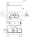
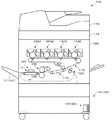
図1に本発明を適用したスタンドアロン型の改質装置の概略を示す。改質装置100は、一般にコピーや印刷等に用いられる普通紙の他、OHPシートを含む樹脂フィルムや、カード、ハガキ等の厚紙、封筒等の何れをもシート状言い換えると枚葉状の被加工物Sとし、その表面である被加工面の改質を行うことが可能である。
FIG. 1 shows an outline of a stand-alone reformer to which the present invention is applied. The
改質装置100において改質を行う被加工面はその少なくとも一部が疎水性であって、この疎水性の被加工面を改質により親水化することを、改質装置100の改質は主目的としている。また、改質装置100は、改質された被加工物Sが、改質によって可能となった加工、たとえばニスの塗工を施されることに供されるようにするために、改質を行う。
At least a part of the work surface to be modified in the
改質装置100は、かかる改質を行う改質部10と、改質部10を収容した本体99と、本体99内に備えられ本体99内の空気を本体99外に排出する排気手段としての排気装置である排気部20と、本体99外から改質部10に向けて被加工物Sを供給する給送手段としての給送装置である給送部30と、本体99外に設けられ改質部10において改質された被加工物Sを積載する積載手段としての積載装置である積載部40と、改質装置100の動作全般を制御するCPU、メモリ等を含む制御手段91と、本体99の上部に配設され、給送部30から被加工物Sを改質部10に供給して改質を開始するための指示を行うための図示しない入力部、後述する所定の表示を行うための図示しない表示部等を備えた操作パネル93とを有している。
The
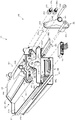
改質部10は、給送部30から給送されてきた被加工物Sの表面を改質しながら積載部40に向けて搬送する表面処理ユニットとしての改質ユニット80と、改質ユニット80を回転可能に支持した図2ないし図5に示す支持手段85と、改質ユニット80を、図1、図3、図5に示した状態である第1の態位としての正位置と、図4に示した状態である第2の態位としての逆位置との何れかで位置決めし、これら複数の位置で改質ユニット80により改質を可能とするための位置決め手段45とを有している。
The reforming
改質部10はまた、改質ユニット80に後述するように備えられた搬送ベルト12を回転駆動の態様で走行駆動し移動させる駆動系としての図6に示す駆動手段17と、図1、図3ないし図5に示すように支持手段85によって支持され改質ユニット80において改質を行うための電力を改質ユニット80に供給する高圧供給電源ユニットとしての電源ユニットである高圧電源56とを有している。
The reforming
改質部10はまた、改質ユニット80と支持手段85と高圧電源56とを一体で本体99に対して図1の紙面に垂直な方向にスライド可能にガイドしたガイド手段95と、図7に示すように位置決め手段45と一体に配設され位置決め手段45による改質ユニット80の位置決め状態を検知する検知手段としてのセンサ33とを有している。
The reforming
改質ユニット80は、被加工物Sを搬送するための搬送手段11と、搬送手段11に対向配置され、搬送手段11によって搬送されている被加工物Sの被加工面に改質を施すための改質手段50とを有している。
The reforming
搬送手段11は、給送部30から給送されてきた被加工物Sを改質しながら積載部40に向けて搬送するために図1において反時計方向または時計方向に回転する態様で移動する被加工物搬送部材としての搬送部材たる無端のベルトである搬送ベルト12と、搬送ベルト12を巻き掛けられ支持した互いに隣り合う2つの支持部材としてのベルト搬送ローラであるローラ13、14と、ローラ13、14を回転自在に支持した図3ないし図5に示すローラ支持体47とを有している。
The conveying means 11 moves in a manner that rotates counterclockwise or clockwise in FIG. 1 in order to convey the workpiece S fed from the
搬送手段11はまた、図2ないし図5に示すようにローラ13、14をそれぞれ互いに離間する方向に付勢し搬送ベルト12に張力を与えローラ13、14をともにテンションローラとしてのテンション付与ローラであるテンション付与部材として機能させるための付勢部材としての圧縮ばねであるばね15、16と、図5等に示して後述するダクト連結部材35に連結される閉止部材36とを有している。
As shown in FIGS. 2 to 5, the conveying
搬送ベルト12は、その移動方向に直交する幅方向が図1の紙面に垂直な方向に一致している。以下、この方向を幅方向という。搬送ベルト12は、図示を省略するが、アルミニウム等の金属あるいはシリコンゴム等の基材に金属粒子等を分散した導電性の無端状の基体と、基体の外周面側にコーティング等によって形成されたシリコン製の誘電性の表面層とを有し、誘電体ベルトとなっている。表面層は実質的に絶縁性の抵抗値を有している。
ローラ支持体47は、ローラ13、ローラ14のそれぞれの軸の両端部を回転自在に指示するように、本体99の前面側と背面側とに一対備えられている。
The
A pair of roller supports 47 are provided on the front side and the back side of the
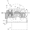
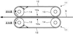
改質ユニット80が正位置に位置決めされても、逆位置に位置決めされても、図8に示すように、搬送ベルト12は、ローラ13とローラ14との間で張架され張り渡されて形成された、太線の矢印で示すように被加工物Sを搬送する用紙搬送面である搬送面としての平面部分12aにおいて、ほぼ水平方向を向くようになっている。なお、図2において、搬送手段11は、改質ユニット80が正位置となっているときの状態を実線で示されており、改質ユニット80が逆位置となっているときの状態を実線で示されている。
Regardless of whether the reforming
改質ユニット80が正位置となっているとき、ローラ13とローラ14とのうち、ローラ13は、後述するようにして駆動手段17によって回転駆動され駆動ローラとして機能することとなり、搬送ベルト12を図1、図2における反時計方向に回転駆動させ、ローラ14を従動回転させ従動ローラとして機能させる。このとき、ローラ13は、位置決め手段45によって、ばね15の付勢力に抗して定位置に位置決めされているため、ローラ14が実質的にテンション付与部材として機能するようになっている。
When the reforming
改質ユニット80が逆位置となっているとき、ローラ13とローラ14とのうち、ローラ14は、後述するようにして駆動手段17によって回転駆動され駆動ローラとして機能することとなり、搬送ベルト12を図1、図2における時計方向に回転駆動させ、ローラ13を従動回転させ従動ローラとして機能させる。このとき、ローラ14は、位置決め手段45によって、ばね16の付勢力に抗して定位置に位置決めされているため、ローラ13が実質的にテンション付与部材として機能するようになっている。
When the reforming
このようにして、搬送ベルト12には、改質ユニット80が正位置となっているか、逆位置となっているかによらず、被加工物Sの搬送に適した所定の張力が与えられる。また、ローラ13とローラ14とのうち、搬送ベルト12の移動方向において、平面部分12aの上流側のローラがテンション付与部材となり、下流側のローラが駆動ローラとなるため、図8において一点鎖線で示すように、かりに、搬送ベルト12にたわみが生じるとしても、たわみは、被加工物Sを搬送する平面部分12aに生じることがないため、被加工物Sは、平面部分12aにより滑らかに搬送されて移動し、後述のようにして行われる改質が、ムラなく良好に行われる。なお、ばね15、16を一体の部材とするなどして、平面部分12aの下流側のローラも同時にテンション付与部材として機能するようにしてもよい。
In this way, the
搬送ベルト12及び搬送ベルト12を巻き掛けたローラ13、14は、次に述べるように改質手段50において放電が生じプラズマが形成されるように、接地されている。
The
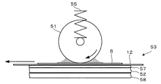
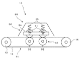
図1に示すように、改質手段50は、搬送ベルト12によって搬送されている被加工物Sの被加工面に対向するように、平面部分12aに対向して配置され、かかる被加工面に接触してこの被加工面の改質を行うためのプラズマを、この被加工面に向けて形成するためのローラ状の放電電極である放電電極ローラ51と、放電電極ローラ51との間でかかるプラズマを発生させるための対向電極としてのカウンター電極52を備えた対向電極部53とを有している。
As shown in FIG. 1, the reforming
改質手段50はまた、放電電極ローラ51を回転自在に支持した支持部材54と、対向電極51を搬送ベルト12、対向電極部53に向けて付勢する付勢部材としての押圧バネであるバネ55と、かかるプラズマの生成とともに発生したオゾン等を排気部20に向けて排出するための排出部34とを有している。
The reforming means 50 also includes a
放電電極ローラ51は、搬送ベルト12の移動方向に沿って複数、具体的には2つ配設されている。これら放電電極ローラ51は互いに同一径の金属ローラである。各放電電極ローラ51は、幅方向に一致する、かかる移動方向に垂直な方向に延在しており、互いに平行に配設されている。各放電電極ローラ51は、搬送ベルト12の幅方向において搬送ベルト12の配設領域と一致するように配設されている。放電電極ローラ51は、金属部分が露出しているが、誘電体あるいは絶縁体で被覆するようにしても良い。
A plurality of, specifically two,
対向電極部53は、カウンター電極52の他に、カウンター電極52の上面を覆うとともに搬送ベルト12の下面を支持するように配設され、カウンター電極52の絶縁層として機能するガラス板57と、カウンター電極52及びガラス板57を下方から支持した平板状の絶縁体58とを有している。
In addition to the
カウンター電極52は、アルミニウム製の平板であってアースされている。カウンター電極52は、搬送ベルト12の移動方向及び幅方向において複数の放電電極ローラ51が配設されている領域を含むように配設されている。
The
支持部材54は、各放電電極ローラ51に備えられ放電電極ローラ51の回転中心をなす軸部を回転自在に支持した図示しない導電性の軸受けと、各軸受けを上下方向すなわち搬送ベルト12、対向電極部53に接離する方向に摺動自在に支持した、同方向に延在した図示しない長孔を備えた導電性の図示しない軸受け支持部材とを有している。軸受けと軸受け支持部材との間には導電性グリスが塗布され、軸受けが長孔により軸受け支持部材に対して摺動しても、軸受け支持部材と放電電極ローラ51とが軸受けを介して導通が良好に保たれるようになっている。
The
バネ55は、かかる軸受けを介して各放電電極ローラ51を搬送ベルト12、対向電極部53に向けて付勢するように複数備えられており、各放電電極ローラ51を搬送ベルト12又はこれによって搬送されている被加工物Sの被加工面に当接させる。よって、各放電電極ローラ51は、搬送ベルト12又はこれによって搬送されている被加工物Sの被加工面の移動に連れ回りする。この連れ回りにより、各放電電極ローラ51は、放電による偏磨耗が低減される。
A plurality of
高圧電源56は、放電電極ローラ51と平面部分12aとに挟まれた被加工物Sの被加工面に接触してこの被加工面の改質を行うためのプラズマを形成するための電圧を放電電極ローラ51に印加するための電源である。
The high-
高圧電源56は、図3、図4に示すように、本体99の前面側に位置し、出力を行う給電ケーブルすなわち放電用の高圧ケーブルによって構成されたハーネス56aと、本体99の背面側に位置し、本体99側に備えられた図示しない電源である交流電源に接続された図5に示す電気接点であるコネクタ59に接続され、本体99側から電力供給を受ける電気的接点であるドロワコネクタ56bとを有している。
As shown in FIGS. 3 and 4, the high-
高圧電源56は、交流電源からのパルスをトランスで昇圧し、高圧パルスの出力を行うものである。そのため、インバータ2次側で高圧側となっているハーネス56aは、軸受け支持部材に電気的に接続され、軸受け支持部材、各軸受けを介して各放電電極ローラ51に計1kW出力相当のパルス状の高電圧を印加可能となっている。なお、各バネ55も、各軸受け支持部材、各軸受け、各放電電極ローラ51と同電位に保たれる。
コネクタ59は本体99の背面側の定位置に固定されており、インバータ1次側で低圧側となっている。
The high
The connector 59 is fixed at a fixed position on the back side of the
このような構成の改質手段50においては、高圧電源56によって放電電極ローラ51に高電圧が印加されると、カウンター電極52との間で放電が生じ、カウンター電極52に向けてプラズマが形成される。かかる放電は、大気圧プラズマ放電、誘電体バリア放電といわれるものである。かかる放電が行われ、かかるプラズマが形成されるにあたり、搬送ベルト12の導電性の基体も、対向電極言い換えるとカウンター電極として機能する。この点、搬送ベルト12も、対向電極部53を構成しているといえる。
In the reforming means 50 having such a configuration, when a high voltage is applied to the
このように、搬送ベルト12もカウンター電極として機能することにより、図9に示すように、放電電極ローラ51から搬送ベルト12あるいはこれによって搬送されている被加工物Sに向けて沿面放電によるプラズマが形成される。沿面放電によるプラズマは、被加工物Sの被加工面に対する接触面積が大きいため、被加工面の改質のムラが抑制され、被加工面の改質の均一性が高い精度で確保される。搬送ベルト12がカウンター電極として機能することは、沿面放電を良好に発生させるという利点、放電電極とカウンター電極との距離が近づくためエネルギーの損失が減少し、またかかる放電、プラズマが生じ易くなるという利点がある。これらの利点、特に前者の利点は、後述するように、カウンター電極がローラ状をなす場合(図19参照)に特に顕著である。なお、カウンター電極がカウンター電極52のように平板状である場合には、搬送ベルト12をカウンター電極として機能させることは必須でなく、搬送ベルト12の基材をポリイミド等によって構成しても良い。かかる放電、プラズマを生じさせるには、放電電極側、カウンター電極側の一方が誘電体あるいは絶縁体によって被覆されていることを要し、この点から上述のように放電電極ローラ51を被覆しても良い。
Thus, the
放電電極ローラ51が搬送ベルト12の移動方向に沿って複数配置されていること、及び、各放電電極ローラ51が搬送ベルト12又はこれによって搬送されている被加工物Sの被加工面に連れ回りすることで沿面放電やプラズマを形成する部位が変化することも、被加工面の改質の均一性を向上している。なお、放電電極ローラ51の数は、本形態のような2つに限られるものでなく、被加工面の改質の均一性を担保しつつエネルギーの損失が抑制されるように適宜設定される。また、平面部分12aにおける搬送ベルト12のその移動方向における長さは、同方向における被加工物Sの長さにかかわらず、放電電極ローラ51からの沿面放電やプラズマによる改質作用が働く領域の同方向における長さ以上であればよい。
A plurality of
高圧電源56による各放電電極ローラ51への印加電圧は、制御手段91によって制御されるが、かかる沿面放電を生じプラズマを生じさせる場合、かかる印加電圧はこれに十分な大きさとされる。また、かかる印加電圧によって生じるプラズマにより被加工面に与えられるエネルギーの密度は、被加工物Sが搬送ベルト12によって搬送されその被加工面がすべての放電電極ローラ51との対向領域すなわち沿面放電によるプラズマの影響を受ける範囲を通過したときに、かかる被加工面の改質が完了する大きさであって、且つ、改質に必要な大きさよりも過大となることのない大きさとされる。
The voltage applied to each
被加工物Sは、改質手段50を通過する際に、かかる放電、プラズマによって、空気中の成分や被加工物S自体に含まれている成分によって形成された種々の親水性官能基等の基が被加工面に形成されて表面エネルギーが高くなり、たとえば被加工面に疎水性を有する部分を含んでいる場合にかかる部分が親水化されることにより、被加工面の改質が行われる。
When the workpiece S passes through the modifying
図1または図3または図5または図10に示すように、排出部34は、搬送ベルト12側が開口しているとともに放電電極ローラ51と支持部材54とバネ55とを搬送ベルト12の逆側から覆い、かかる沿面放電やプラズマによって生じた、オゾン等の気体生成物や熱が排気部20以外の外部に漏れることを抑制したオゾン排気ダクトとしてのダクト34aと、ダクト34aの背面側上部に突設されているとともに排気部20に備えられたダクト連結部材35に連結されかかる気体生成物や熱を排出するための排出口としてのオゾン排気口である排気口34bとを有している。
As shown in FIG. 1, FIG. 3, FIG. 5, or FIG. 10, the
支持手段85は、図1における左右方向から見た状態でほぼU字状をなしたユニット支持体である支持体としてのフレーム37と、フレーム37に固定されて支持され改質ユニット80を回転可能に支持した、幅方向をその軸方向とした回転軸38とを有している。
The support means 85 can rotate the reforming
図3ないし図5に示すように、フレーム37は、幅方向に長い平板状をなした平板部37aと、幅方向における平板部37aの前端、後端にそれぞれ改質ユニット80側への屈曲によって形成され回転軸38を固定支持した起立部37b、37cとを有している。
As shown in FIGS. 3 to 5, the
平板部37aは、起立部37b、37cが形成されている側と反対側で高圧電源56を固定支持している。
起立部37bは、図3、図4に示すように、ハーネス56aを挿通されている。
起立部37cは、図5に示すように、改質ユニット80が逆位置となっている状態において、幅方向で閉止部材36と直線上に位置する孔37dを有している。
The
As shown in FIGS. 3 and 4, the standing
As shown in FIG. 5, the standing
回転軸38は、起立部37bに支持された部分と、起立部37cに支持された部分とに分割されている。これらの各部分の一端が、起立部37b、起立部37cに固定されており、他端は、各ローラ支持体47を回転可能に支持している。よって、回転軸38は、これらの部分でそれぞれ、改質ユニット80の前面側と、背面側とを回転可能に支持している。これらの各部分は、幅方向で直線上に位置している。回転軸38の、起立部37bに支持された部分は、中空形状をなしており、起立部37cに支持された部分は、中実形状をなしている。
The rotating
回転軸38の、起立部37bに支持された部分は、図11に示すように、中空状のパイプ部38aと、パイプ部38aにカシメによって締結され一体化されたフランジ部38bとを有している。フランジ部38bをパイプ部38aに一体化する方法は他の方法であっても良い。
回転軸38の、起立部37bに支持された部分は、フランジ部38bにおいて、起立部37bに固定されているとともに、パイプ部38a内を、ハーネス56aが通っている。
As shown in FIG. 11, the portion of the
The portion of the
支持手段85は、このような構成により、改質ユニット80を、回転軸38を中心に回転可能に支持している。これにより、改質ユニット80は、正位置、逆位置を占めることが可能となっている。ハーネス56aは、回転軸38内を通っていることにより、改質ユニット80が回転しても、絡まることがなく、断線が防止され、高耐久性、安全性が確保されている。
With such a configuration, the
支持手段85は、回転軸38による改質ユニット80の回転中心が、平面部分12aの外面位置に一致するように、回転軸38によって、改質ユニット80を支持している。よって、改質ユニット80が正位置を占めるときと逆位置を占めるときとで反転しても、かかる外面位置は同一位置を占めるとともに、平面部分12a上の被加工物Sすなわち平面部分12aに支持されている被加工物Sは同一位置を占めるようになっている。そのため、搬送ベルト12による被加工物Sの搬送位置は、改質ユニット80が正位置を占めるときと逆位置を占めるときとで同一位置を占める。
The
また、支持手段85は、改質ユニット80が正位置を占めているか、逆位置を占めているかによらず、平板部37aの下方で高圧電源56を支持している。よって、高圧電源56は、フレーム37によって、改質ユニット80の下方に配設されている。より具体的には、フレーム37は、回転軸38をその上方で支持し改質ユニット80をその上方で回転自在に支持しているとともに、高圧電源56をその下方で固定して支持している。また上述のように、ハーネス56aが回転軸38の内部を通っていることで、ハーネス56aの配設経路が短くて済み、ハーネス56aの長さを極力短くすることが可能となっている。
Further, the support means 85 supports the high-
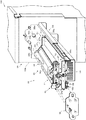
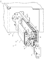
位置決め手段45は、回転軸38を中心に回転し、互いに反転したそれぞれの位置すなわち正位置、逆位置となった改質ユニット80を、それぞれの姿勢で位置決め可能とするものである。そのため、図2ないし図5に示すように、位置決め手段45は、改質ユニット80が正位置となる位置でローラ13の軸を不動となるように位置決めし、改質ユニット80が逆位置となる位置でローラ14の軸を不動となるように位置決めする位置決め部材としての規制部材45aを有している。
The positioning means 45 is configured to be able to position the reforming
規制部材45aは、図3ないし図5に示されているように、幅方向において搬送ベルト12を挟むように一対設けられ、それぞれフレーム37に固定されている。規制部材45aは、改質ユニット80が、回転軸38を中心に、図2において、時計方向に回転するときにローラ13の軸の各端部に当接することで、それ以上の改質ユニット80の回転を規制して改質ユニット80を正位置に位置決めし、反時計方向に回転するときにローラ14の軸の各端部に当接することで、それ以上の改質ユニット80の回転を規制して改質ユニット80を逆位置に位置決めする。このように、規制部材45aという1つの部材によってローラ13の位置決めとローラ14の位置決めとが行われ、回転軸38を中心とした改質ユニット80の回転に対するストッパーとして機能するため、部品点数が抑制され、低コスト化、小型化が図られている。
As shown in FIGS. 3 to 5, a pair of regulating
規制部材45aによってこのようにして位置決めされたローラ13またはローラ14は、駆動手段17と後述するようにして連結される連結位置に位置決めされた状態となり、よって、ローラ13とローラ14とのいずれか一方が、駆動ローラとして機能することとなる。したがって、改質ユニット80は、正位置、逆位置という、平面部分12aの外面位置を中心として対称に反転した複数、具体的には2つの位置で位置決めされ、被加工物Sは、フェイスアップ、フェイスダウンという、表裏反転した複数、具体的には2つの位置で非加工面の改質が行われるようになっている。
The
このようにして位置決め手段45によって正位置、逆位置に位置決めされた改質ユニット80において、排気口34b、閉止部材36は、平面部分12aの外面位置に対して対称すなわち線対称の位置を占めるようになっており、改質ユニット80が正位置を占めたときと逆位置を占めたときとで、排気口34bが占める位置と閉止部材36が占める位置とは、互いに入れ替わり、互いに同じ位置となるように設けられている。
In the reforming
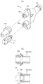
そこで、図10または図12に示すように、ダクト連結部材35は、正位置を占めた改質ユニット80における排気口34bまたは逆位置を占めた改質ユニット80における閉止部材36と連結される中空形状の上側のダクト連結口である第1の吸引口としての連結部35aと、正位置を占めた改質ユニット80における閉止部材36または逆位置を占めた改質ユニット80における排気口34bと連結される中空形状の下側のダクト連結口である第2の吸引口としての連結部35bとを有している。
Therefore, as shown in FIG. 10 or FIG. 12, the
ダクト連結部材35はまた、中空形状をなし連結部35aと連結部35bとが合流する態様で連結部35a及び連結部35bと連通し排気部20の本体側に連結されたオゾン吸引口としての吸引口35cと、本体99の内部であって改質ユニット80よりも本体99の背面側に備えられ本体99の背部に位置する後側板である側板99aの定位置に固定されるフランジ35dとを有している。
The
改質ユニット80が正位置となっているか、逆位置となっているかに応じて、2つの連結部35a、連結部35bのうちの何れか一方が排気口34bに選択的に連結されるように、ダクト連結部材35は本体99側の所定位置に固定して設けられている。そして、排気口34bが連結部35aまたは連結部35bと連結されると、ダクト34a内部の空間と、吸引口35cとが連通する。このように、排気口34bと、連結部35a、連結部35bとは、互いに接続されて連通する連結口となっている。
Depending on whether the reforming
閉止部材36は先端部にスポンジシール36aを有した中実の部材であり、連結部35bまたは連結部35aと連結されると、その連結された連結部35bまたは連結部35aを閉止して封止する。よって、閉止部材36は、2つの連結部35a、35bのうち、排出口34bと連結された連結部と異なる連結部を塞ぐキャップ部として備えられたものとなっている。
The closing
したがって、ダクト連結部材35は、2つの連結部35a、35bを有し2股に分かれ内部で吸引口35cと連通した形状となっているが、改質ユニット80が正位置、逆位置の何れに位置決めされても、吸引口35cと連通するのはその一方のみであり、他方は封止されるため、排気部20によって後述のようにして形成される負圧の損失が生じることがなく、ダクト34a内の排気が良好に行われる。
Therefore, the
また、上述のようにして位置決め手段45によって正位置、逆位置に位置決めされた改質ユニット80において、連結位置に位置決めされたローラ13と、連結位置に位置決めされたローラ14とは、平面部分12aの外面位置に対して線対称の位置を占めるようになっている。
Further, in the reforming
そのため、駆動手段17は、図6等に示して後述するように、連結位置に位置決めされたローラ13、連結位置に位置決めされたローラ14に連結される構造を有している。
なお、図3、図4において、ダクト連結部材35の図示を省略しており、代わりに、側板99aに形成され、連結部35a、35bを挿通される孔99b、99cを示している。
Therefore, as shown in FIG. 6 and the like, the driving
3 and 4, the illustration of the
ガイド手段95は、図1、図3ないし図5に示すように、フレーム37の下方に一対備えられている。各ガイド手段95は、本体99側に固定されたスライドレールとしてのレール部材95aと、レール部材95aに支持され改質ユニット80と支持手段85と高圧電源56とに一体化されたガイド部としてのスライドレール95bと、改質ユニット80と支持手段85と高圧電源56とを一体で図1における紙面手前側に引き出したときにスライドレール95bがレール部材95aから離脱することを防止する図5に示す離脱防止部95cとを有している。
As shown in FIGS. 1 and 3 to 5, a pair of guide means 95 is provided below the
ガイド手段95は、改質ユニット80と支持手段85と高圧電源56とを一体で、図3ないし図5に示すように、本体99外部に引き出した引き出し位置と、図10に示すように、本体99内部に格納した格納位置との間で、改質ユニット80と支持手段85と高圧電源56とを一体でスライド可能に支持する態様でガイドしている。
The
離脱防止部95cは、引き出し位置において、改質ユニット80と支持手段85と高圧電源56とをそれ以上図1における紙面の手前側に引き出すことを禁止する、レール部材95aに配設された図示しない係合部と、スライドレール95bに配設された図示しない被係合部とを有している。ただし、メンテナンス性等を考慮して、引き出し位置よりも格納位置側で、スライドレール95bは、改質ユニット80と支持手段85と高圧電源56とともに持ち上げる解除操作により、レール部材95aとの係合状態が解除され、レール部材95aから取り外し可能となっている。
The
改質ユニット80と支持手段85と高圧電源56とが格納位置を占めると、排気口34b、閉止部材36が連結部35a、連結部35bと連結されてダクト34a内の排気を行うことが可能となるとともに、ドロワコネクタ56bがコネクタ59に連結され、交流電源から高圧電源56への給電が可能となる。また、後述するように、ローラ13またはローラ14が駆動手段17に連結され、搬送ベルト12の回転駆動が可能となる。
When the reforming
これらの連結によっても、回転軸38を中心とした改質ユニット80の回転が規制されるため、改質ユニット80と支持手段85と高圧電源56とが格納位置を占めた状態で、ダクト連結部材35、コネクタ59、駆動手段17も、位置決め手段45として機能することとなる。
These connections also restrict the rotation of the reforming
回転軸38を中心とした改質ユニット80の回転は、図3、図4に示すように、改質ユニット80と支持手段85と高圧電源56とが、引き出し位置など、本体99の筐体99bの外部に引き出された状態において行うことが可能となる。
As shown in FIGS. 3 and 4, the reforming
よって、改質ユニット80を、正位置、逆位置の一方から他方に変位させる操作が、改質ユニット80を本体99の外部に引き出し、回転軸38を中心として回転させ、本体99の内部に押し込んで格納位置に装着するという、ユーザーの目視を伴うことによる確実な、かつ容易な動作によって完了する。
Therefore, the operation of displacing the reforming
また、すでに述べたように、高圧電源56が改質ユニット80の下方に配設されていることから、高圧電源56がかかる操作の邪魔になりにくく、かかる操作が容易に行われるとともに、一般に重量のある高圧電源56を改質ユニット80の下方に配設したことで、重心が下方に位置し、安定性が高いことによっても、かかる操作、とくに改質ユニット80を本体99の外部に引き出して行う回転動作の操作性が良好となっている。
Further, as already described, since the high-
高圧電源56がフレーム37により固定されて改質ユニット80の下方に位置し、かかる操作を行うときに、改質ユニット80の回転とともに回転することがなく、改質ユニット80のみを回転させれば、正位置、逆位置相互間の変位が行われるため、これによっても、かかる操作は容易であり、またこれに加えて、高圧電源56の電磁波ノイズ対策が容易になっている。すなわち、かりに、高圧電源56が改質ユニット80の回転操作時に移動する構成となっているとすれば、その移動範囲において高圧電源56の電磁波ノイズ対策を施す必要があるが、改質装置100においては、高圧電源56が改質ユニット80の回転操作時に移動することのない構成となっているため、高圧電源56は、フレーム37の下方に位置しているその位置においてのみ、電磁波ノイズ対策を施されれば良く、電磁波ノイズ対策が容易となっている。
When the high-
さらに、かかる操作を行うときに、離脱防止部95cにより、改質ユニット80の脱落が防止されるため、安全が確保されているとともに、改質ユニット80の破損が防止されている。改質ユニット80には、一般に重量のある高圧電源56が一体化されているが、改質ユニット80とともに高圧電源56についても脱落が防止されるため、高圧電源56についても破損が防止されており、また安全性が高くなっている。
Furthermore, when performing such an operation, the
なお、図3、図4において、符号39は、筐体99bに着脱される面板を示しており、かかる引き出しを行うときには、面板39を筐体99bから取り外してからこれを行う。改質ユニット80と支持手段85と高圧電源56とを格納位置に位置決めしたときに面板39を筐体99bに装着すると、筐体99bの内部の空間が閉鎖され、改質装置100が動作可能となる。
3 and 4,
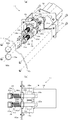
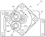
図6または図13に示すように、駆動手段17は、搬送ベルト12を回転駆動して被加工物Sを搬送させるための駆動源としてのモータ18と、モータ18を固定されるとともに側板99aに固定されたモータ支持体としての支持体19と、支持体19と側板99aとに支持された第1の駆動部28、第2の駆動部29とを有している。
As shown in FIG. 6 or FIG. 13, the driving means 17 has a
第1の駆動部28は、モータ18の出力ギア18aに噛合したギア28aと、ギア28aの回転中心軸である、幅方向に延設された駆動軸としての軸28bと、軸28bを支持体19、側板99aにそれぞれ回転自在に支持するための軸受28c、28dと、軸28bの先端部に、幅方向に移動可能に設けられた軸継手としてのカップリング28eと、カップリング28eと軸受28dとの間の部分の軸28bに巻き付けられカップリング28eを側板99aから離れる方向に付勢した付勢部材としての圧縮ばねであるばね28fと、カップリング28eが軸28bから離脱することを防止した離脱防止部材としての図示しないリングとを有している。
The
第2の駆動部29は、ギア28aに噛合したギア29aと、ギア29aの回転中心軸である、幅方向に延設された駆動軸としての軸29bと、軸29bを支持体19、側板99aにそれぞれ回転自在に支持するための軸受29c、29dと、軸29bの先端部に、幅方向に移動可能に設けられた軸継手としてのカップリング29eと、カップリング29eと軸受29dとの間の部分の軸29bに巻き付けられカップリング29eを側板99aから離れる方向に付勢した付勢部材としての圧縮ばねであるばね29fと、カップリング29eが軸29bから離脱することを防止した離脱防止部材としての図示しないリングとを有している。
The
図13に示すように、モータ18が駆動され出力ギア18aが同図における反時計方向に回転駆動されると、ギア28aが出力ギア18aと反対方向すなわち同図における時計方向に回転駆動され、さらにギア29aがギア28aと反対方向すなわち同図における反時計方向に回転駆動される。したがって、カップリング28eとカップリング29eとは、互いに逆方向に回転駆動される。
なお、図6において、符号99d、99eはそれぞれ、側板99aに形成され軸受28d、29dを嵌合された孔を示している。
As shown in FIG. 13, when the
In FIG. 6,
モータ18は、制御手段91によって駆動を制御される。モータ18は、制御手段91によって制御されることで、1速から5速の間で回転速度が可変である。よって、これに応じて、搬送ベルト12の回転速度も1速から5速の間で可変となっている。搬送ベルト12は、最大で、A4横サイズで90枚/分程度の速度で回転する。
The drive of the
図5を参照して、改質ユニット80と支持手段85と高圧電源56とをガイド手段95によって幅方向に移動させ、格納位置に位置決めすると、改質ユニット80が正位置を占めているときには、ローラ13がカップリング29eと連結されて軸29bと一体で回転駆動可能な状態となって、ローラ13が駆動ローラとして機能可能な状態となり、改質ユニット80が逆位置を占めているときには、ローラ14がカップリング28eと連結されて軸28bと一体で回転駆動可能な状態となって、ローラ14が駆動ローラとして機能可能な状態となる。
Referring to FIG. 5, when the reforming
これらの連結によって、すでに述べたように、回転軸38を中心とした改質ユニット80の回転が規制されるため、駆動手段17において、第1の駆動部28、第2の駆動部29が位置決め手段45として機能することとなる。
As described above, the rotation of the reforming
また、ローラ13とカップリング29eとの連結が行われるときにはばね29fがこの連結の際すなわち格納位置に位置決めした状態となる際の衝撃を吸収する緩衝部材として機能し、ローラ14とカップリング28eとの連結が行われるときにはばね28fがこの連結の際すなわち格納位置に位置決めした状態となる際の衝撃を吸収する緩衝部材として機能する。
Further, when the
このような構成により、改質ユニット80が、正位置を占めているときにも、逆位置を占めているときにも、駆動手段17によって搬送ベルト12が回転駆動されることとなる。また、カップリング28eとカップリング29eとが互いに逆方向に回転駆動されるため、図2、図8に示すように、搬送ベルト12の回転方向言い換えると被加工物Sの搬送方向が改質ユニット80の正位置、逆位置において互いに逆転され、改質ユニット80における被加工物Sの搬送方向が一方向に保たれる。このように、搬送ベルト12の回転方向は、改質ユニット80が、正位置を占めているときと、逆位置を占めているときとで互いに逆方向であるから、改質ユニット80が、正位置を占めているときにも、逆位置を占めているときにも、搬送ベルト12による被加工物Sの搬送は、給送部30から積載部40に向けた方向に行われることとなる。
With such a configuration, the
よって、本体99内の、給送部30から積載部40に向けた被加工物Sの搬送経路は、改質ユニット80が、正位置を占めているときと逆位置を占めているときとで一致し、共通であって不変であり、単純化されており、ジャム等の不具合が発生しにくくなっている。
Therefore, the conveyance path of the workpiece S from the
そして、搬送ベルト12は、改質ユニット80が、正位置を占めているときにも、逆位置を占めているときにも、最大で、A4横サイズで90枚/分程度の速度で、給送部30から積載部40に向けて、被加工物Sを搬送する。
The
また、ローラ13、ローラ14は、このようにして回転駆動されるため、図8に示してすでに述べたように、ローラ13とローラ14とのうち、搬送ベルト12の移動方向において、平面部分12aの上流側のローラがテンション付与部材となり、下流側のローラが駆動ローラとなることから、平面部分12aにはたわみが生じることがなく、平面部分12aによって行われる被加工物Sの搬送は、滑らかであって、改質がムラなく良好に行われる。
Since the
この搬送の際、被加工物Sは、改質ユニットが正位置を占めているときは、搬送ベルト12の平面部分12aの上面に沿って搬送され、その上面である被加工面が改質され、改質ユニットが逆位置を占めているときは、搬送ベルト12の平面部分12aの下面に沿って搬送され、その下面である被加工面が改質される。
During the conveyance, when the reforming unit occupies the normal position, the workpiece S is conveyed along the upper surface of the
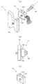
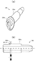
図7に示すように、センサ33は、規制部材45aの、ローラ13の位置決めを行う部分と、ローラ14の位置決めを行う部分との間に、ねじ46によって固定されるようになっている。
As shown in FIG. 7, the
センサ33は、同図(a)、(b)に示されているように、リードセンサであっても良いし、同図(c)に示されているように、反射型光学センサであっても良いし、他のタイプのセンサであっても良い。
The
同図(a)、(b)に示されているセンサ33は、規制部材45aがローラ13の位置決めを行い改質ユニット80が正位置に位置決めされたときにローラ13に当接して押し込まれるスイッチ33aと、規制部材45aがローラ14の位置決めを行い改質ユニット80が逆位置に位置決めされたときにローラ14に当接して押し込まれるスイッチ33bとを有している。
The
同図(c)に示されているセンサ33は、ローラ13またはローラ14が規制部材45aによって位置決めされたことを反射光の有無によって検知するものである。そのため、このセンサ33は、上面側に、規制部材45aによってローラ14の位置決めを行われたときにローラ14が占めるべき位置に向けて光を発する発光素子33cと、このときにローラ14によって反射された光を受ける受光素子33dとを、その上面側に有している。このセンサ33は上面側と同様に、その下面側に、規制部材45aによってローラ13の位置決めを行われたときにローラ13が占めるべき位置に向けて光を発する図示しない発光素子と、このときにローラ13によって反射された光を受ける図示しない受光素子とを有している。
The
このような構成により、センサ33によって、改質ユニット80が正位置を占めている状態であるか、逆位置を占めている状態であるか、正位置、逆位置と異なる位置を占めている状態であるかの何れかで、改質ユニット80の位置決め状態が検知される。より具体的には、センサ33は、検知信号を制御手段91に入力し、制御手段91が、改質ユニット80と支持手段85と高圧電源56とが格納位置に位置決めされたとき、かかる何れの状態であるかを判断するようになっている。
With such a configuration, the
制御手段91は、かかる判断によって得られた情報を表示部に表示させる。具体的には、かかる状態の何れとなっているかを表示する。これにより、本体99内の改質ユニット80の状態がユーザーによって確認され認識される。
The control means 91 displays the information obtained by such determination on the display unit. Specifically, it is displayed in which state. Thereby, the state of the reforming
また、かかる表示とともに、あるいはかかる表示に代えて、改質ユニット80が正位置、逆位置の何れをも占めていない状態のときには、その旨、あるいは改質ユニット80を正位置と逆位置との何れかに位置決めすべき旨の警告を行うことが望ましい。この警告によってユーザーに正位置あるいは逆位置への位置決めを促し、かかる位置決めが行われれば、被加工物Sのジャムその他改質装置100における不具合を防止することが可能となるためである。表示部は、このような表示を行うことが可能なように、液晶表示装置、LEDなどを備えた構成となっている。
When the reforming
改質装置100が、後述するように、画像形成装置の後処理装置に用いられる場合には、画像形成装置の表示部にこのような表示を行ってもよい。また、かかる場合には、後述するように、画像形成装置側から被加工物Sにおける画像形成面の向きがフェイスアップ、フェイスダウンの何れであるかなど、被加工物Sのいずれの面を被加工面とすべきかに関する情報を取得し、改質ユニット80の位置決め状態がこれと合致していない場合に、その旨の表示を行うことによる警告を行うようにしてもよい。
As will be described later, when the reforming
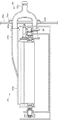
排気部20は、上述した沿面放電やプラズマによって生じた、オゾン等の気体生成物を除去したうえで、本体99内の空気を本体99外に排出し換気を行うとともに、この換気により熱を排出することで、本体99内を清浄な状態に保ち、改質に適した状態に維持するものである。
The
排気部20は、かかる排気を行うための空気流を形成する空気流形成手段としてのファン21を備えた空気流形成部22と、ファン21によって形成された本体99内の空気流により本体99内の空気が空気流形成部22に至るまでにかかる空気中のオゾンなど、本体99外にそのまま排気すると環境に与え得る成分を除去する浄化部23と、ダクト連結部材35を備え浄化部23と改質部10とを連結したダクトとして機能する連結部26とを有している。
The
空気流形成部22は、ファン21の駆動により、浄化部23、連結部26、排出部34側に負圧を生させ、ダクト34aの開口から空気を吸引する吸引力を発生させることで、かかる空気流を形成する。上述した沿面放電やプラズマによって生じた、オゾン等の気体生成物は、この空気流に乗って、連結部26を経て、浄化部23に進入する。このように、浄化部23と連結部26とは本体99側の吸引路として機能し、排出部34は改質ユニット80側の吸引路として機能するようになっている。
The air
浄化部23は、その内部の空気の流路に沿って、MgO2触媒を用いた第1のフィルタとしての複数のオゾンフィルタ24と、活性炭繊維触媒を用いた第2のフィルタとしての複数のオゾンフィルタ25とを有している。浄化部23は、本体99内で発生する気体生成物に応じて、オゾン以外の成分を除去する他のフィルタ等を備えていても良い。浄化部23によって浄化された本体99内の空気は、熱とともに、本体99外部に排出される。
The
給送部30は、本体99外に配設され複数枚の被加工物Sを積載したトレイ31と、トレイ31上に積載された被加工物Sを改質部10に向けて1枚ずつ送り出す図示しない給送手段とを有している。
The
積載部40は、本体99外に配設され改質部10において改質された被加工物Sを多数枚積載可能な積載トレイ41を有している。
積載トレイ41に積載された被加工物Sは、改質によって可能となった加工に供される。たとえば、改質前に被加工面が疎水性の場合にはニスの塗工を施してもニスがはじかれて光沢ムラが生じるようになっていても、改質を行いかかる疎水性の部分が親水化されると、ニスが被加工面の全体になじみ、光沢ムラが防止ないし抑制され質感が向上するとともに、耐久性も向上する。
The stacking
The workpieces S loaded on the stacking
制御手段91は、放電電極ローラ51によって形成されるプラズマの形成タイミング及び強度を制御するプラズマ制御手段として機能するようになっている。これは、プラズマを用いる技術では、省エネルギーの観点から、プラズマを発生させるエネルギーを極力小さくすることが求められるという観点から、被加工物Sの非通過時にプラズマを発生させたり、被加工面の状態によって定まる必要なプラズマの強度よりも大きな強度でプラズマを発生させたりすることを防止ないし抑制し、エネルギーの無駄を生じることを防止ないし抑制するためである。
The control means 91 functions as a plasma control means for controlling the formation timing and intensity of the plasma formed by the
高圧電源56による各放電電極ローラ51への電圧印加から放電開始あるいはプラズマの形成までの応答性は数msecであって極めて高いことから、プラズマ制御手段として機能する制御手段91は、給送部30によって被加工物Sが送り出されるタイミングに応じて、各放電電極ローラ51が適正なプラズマを発生するように高圧電源56を駆動することで、改質に必要なエネルギーを被加工面に与える。
Since the responsiveness from the voltage application to each
また、各放電電極ローラ51と搬送ベルト12との間に被加工物Sが存在せず搬送ベルト12が露出した状態となる場合には、搬送ベルト12が露出した範囲に沿面放電あるいはプラズマが作用することのないように、適切なタイミングで高圧電源56による各放電電極ローラ51への電圧印加を停止しかかる露出した範囲における搬送ベルト12へのプラズマの接触を停止するようになっており、消費エネルギーの抑制、搬送ベルト12の劣化抑制を成している。
Further, when there is no workpiece S between each
以上のように構成された改質装置100によって被加工物Sの改質を行うことにより、被加工物Sの加工が良好に行われることとなり、被加工物Sの市場における価値が向上する。改質装置100は、エネルギーの浪費を防止ないし抑制して被加工物Sの改質を行ものであり、また、被加工物Sを搬送しながら改質することで多量の被加工物Sを一括して改質可能となっていることから、使用感が極めて高い。
By modifying the workpiece S by the reforming
さて、以上述べた改質装置100は、これによって改質を行う被加工物Sを特に限定していないが、被加工物Sとして、たとえば、画像形成装置によって画像形成が行われた出力物を用いることが可能である。
The reforming
画像形成装置には種々あるが、乾式トナー等を用いて画像形成を行う、たとえば複写機、ファクシミリ、プリンタ、これらの複合機等の画像形成装置においては、この画像形成装置による画像形成を行う過程で、普通紙等の記録媒体が疎水性を発揮するようになる加工が行われる。すなわち、トナーが固体パラフィン等のワックスを含むワックス含有トナーである場合には、かかるトナーによって形成されたトナー像を記録媒体に定着させるときに、トナー中のワックス成分がトナー像表面に滲出し、トナー像部分が疎水性を発揮する出力物が形成される。また、トナーがワックス含有トナーでない場合であっても、かかる画像形成装置に、記録媒体に画像を定着させる定着装置が備えられている場合であって、かかる定着装置において、定着装置側に記録媒体や画像が付着することを防止ないし緩和するために、記録媒体や画像にシリコンオイル等の疎水性の離型剤が塗布される場合には、やはり、記録媒体表面が疎水性を発揮する出力物が形成される。その他、画像形成装置の出力物でなくとも、それ自体が樹脂製である場合等は、製造により出力物となった時点で疎水性を有する場合がある。 There are various types of image forming apparatuses. For example, in an image forming apparatus such as a copying machine, a facsimile machine, a printer, and a composite machine of these, the image forming process is performed by the image forming apparatus. Thus, processing is performed so that the recording medium such as plain paper exhibits hydrophobicity. That is, when the toner is a wax-containing toner containing a wax such as solid paraffin, the wax component in the toner exudes to the surface of the toner image when fixing the toner image formed by the toner to the recording medium, An output product in which the toner image portion exhibits hydrophobicity is formed. Further, even when the toner is not a wax-containing toner, the image forming apparatus is provided with a fixing device for fixing an image on the recording medium. In the fixing device, the recording medium is provided on the fixing device side. When a hydrophobic release agent such as silicone oil is applied to the recording medium or image in order to prevent or alleviate the adhesion of the image or the image, the output material whose surface is also hydrophobic Is formed. In addition, even if it is not an output product of the image forming apparatus, it may have hydrophobicity when it becomes an output product by manufacturing if it is itself made of resin.
このような出力物は、表面の少なくとも一部が疎水性を発揮するため、親水性を要する加工を施す場合には、かかる表面を改質して親水性をもたせる必要がある。すなわちかかる出力物が改質装置100による改質の対象である被加工面を有する被加工物Sとなる。
In such an output product, at least a part of the surface exhibits hydrophobicity. Therefore, when processing that requires hydrophilicity is performed, the surface needs to be modified to have hydrophilicity. That is, the output product is a workpiece S having a workpiece surface to be modified by the
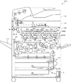
かかる被加工面を有する被加工物Sを出力物とする装置の一例として、図14に示す画像形成装置を説明する。
同図に示す画像形成装置200は、カラーレーザ複写機とプリンタとの複合機であるが、他のタイプの複写機、ファクシミリ、プリンタ、これらの複合機等、他の画像形成装置であっても良い。画像形成装置200は、この画像形成装置200で読み取った原稿の画像データ、または後述する通信部192により外部から受信した画像情報に対応する画像信号に基づき画像形成処理を行う。画像形成装置200は、一般にコピー等に用いられる普通紙の他、OHPシートや、カード、ハガキ等の厚紙や、封筒等の何れをもシート状の記録媒体として画像形成を行い、画像形成後の記録媒体を、表面改質が必要な被加工物Sとなり得る出力物とすることが可能である。
An image forming apparatus shown in FIG. 14 will be described as an example of an apparatus that uses the workpiece S having such a processed surface as an output.
The
画像形成装置200は、イエロー、マゼンタ、シアン、ブラックの各色に色分解された色にそれぞれ対応する像としての画像を形成可能な像担持体としての潜像担持体である円筒状の感光体ドラム70Y、70M、70C、70BKを平行配設したタンデム構造、言い換えるとタンデム方式を採用している。
The
感光体ドラム70Y、70M、70C、70BKは、画像形成装置200の本体199の図示しないフレームに回転自在に支持され、像担持体である転写媒体としての転写ベルト111の移動方向であるA1方向の上流側からこの順で並んでいる。各符号の数字の後に付されたY、M、C、BKは、イエロー、マゼンタ、シアン、黒用の部材であることを示している。
The
各感光体ドラム70Y、70M、70C、70BKはそれぞれ、イエロー(Y)、マゼンタ(M)、シアン(C)、ブラック(BK)の画像を形成するための作像ステーションである画像形成ユニット160Y、160M、160C、160BKに備えられている。
Each of the
感光体ドラム70Y、70M、70C、70BKは、本体199の内部の中央部よりもやや上方に配設された無端のベルトである中間転写体としての転写ベルト111の外周面側すなわち作像面側に位置している。
The
転写ベルト111は、各感光体ドラム70Y、70M、70C、70BKに対峙しながら矢印A1方向に移動可能となっている。各感光体ドラム70Y、70M、70C、70BKに形成された可視像すなわちトナー像は、矢印A1方向に移動する転写ベルト111に対しそれぞれ重畳転写され、その後、記録媒体であり転写媒体である転写紙に一括転写されるようになっている。転写紙の図示は省略している。
The transfer belt 111 is movable in the direction of the arrow A1 while facing the
転写ベルト111に対する重畳転写は、転写ベルト111がA1方向に移動する過程において、各感光体ドラム70Y、70M、70C、70BKに形成されたトナー像が、転写ベルト111の同じ位置に重ねて転写されるよう、転写ベルト111を挟んで各感光体ドラム70Y、70M、70C、70BKに対向する位置に配設された1次転写ローラ112Y、112M、112C、112BKによる電圧印加によって、A1方向上流側から下流側に向けてタイミングをずらして行われる。
In the superimposing transfer to the transfer belt 111, the toner images formed on the
画像形成装置200は、本体199内に、4つの画像形成ユニット160Y、160M、160C、160BKと、各感光体ドラム70Y、70M、70C、70BKの下方に対向して配設され、転写ベルト111を備えた中間転写ユニットとしての転写ベルトユニット110と、転写ベルト111に対向して配設され転写ベルト111に当接し、転写ベルト111への当接位置において転写ベルト111と同方向に回転し無端移動する転写部材としての紙搬送ベルトである2次転写ベルト105を備え転写ベルト111上のトナー像を転写紙に転写するとともに搬送する2次転写装置としての2次転写ユニット176と、画像形成ユニット160Y、160M、160C、160BKの上方に対向して配設された潜像形成手段としての露光装置たる光書込みユニットである光走査装置108とを有している。
The
画像形成装置200はまた、本体199内に、感光体ドラム70Y、70M、70C、70BKと転写ベルト111との間に向けて搬送される転写紙を多数枚積載可能な給紙カセットとしての給紙機構であるシート給送装置161と、シート給送装置161から搬送されてきた転写紙を、画像形成ユニット160Y、160M、160C、160BKによるトナー像の形成タイミングに合わせた所定のタイミングで、転写ベルト111と2次転写ベルト105との間に向けて繰り出すレジストローラ104とを有している。
The
画像形成装置200はまた、本体199内に、トナー像を転写された転写紙に同トナー像を定着させるためのベルト定着方式の定着ユニットとしての定着装置106と、定着済みの転写紙を本体199の外部に排出する排紙ローラ対としての排紙ローラ107と、排出ローラ107により本体199の外部に排出された転写紙を積載する排紙トレイ117とを有している。
The
画像形成装置200はまた、本体199上方に、原稿の画像を読み取るスキャナーである読取装置114と、読取装置114の上方に配設され読取装置114に原稿を給送する自動原稿給送装置(いわゆるADF)115とを有している。
The
画像形成装置200はまた、本体199内の最下方に備えられ本体199内の空気を本体199外に排出する排気手段としての排気装置である排気部120と、種々の検知手段による検知結果等に基づき画像形成装置200の動作全般を制御するCPU、メモリ等を含む制御手段191と、外部から画像形成を行うための画像情報を受信する通信手段としての通信部192とを有している。
The
画像形成装置200はまた、定着装置106から排紙ローラ107に向かう転写紙の搬送経路から分岐し、受け入れた転写紙をスイッチバックさせて表裏反転させた状態で再度レジストローラ104に給送する反転装置109を有している。
したがって、画像形成装置200は、両面画像形成装置となっている。
The
Therefore, the
シート給送装置161は、転写紙を複数枚重ねた転写紙束の状態で収容するものであり、本体199の下部において多段で配設されている。シート給送装置161は、所定のタイミングで、転写紙をレジストローラ104に向けて給送するようになっている。
シート給送装置161から送り出された転写紙は、給紙経路を経てレジストローラ104に至り、レジストローラ104のローラ間に挟まれる。
The
The transfer paper sent out from the
定着装置106は、ベルトユニット162と、ベルトユニット162に圧接された加圧ローラ163とを有している。ベルトユニット162は、無端状の定着ベルト164と、定着ベルト164を張架しながら無端移動させる定着ローラ165と、定着ローラ165とともに定着ベルト164を巻き掛け内部に図示しない熱源を有する加熱ローラ166とを有している
The fixing
定着装置106は、トナー像を担持した転写紙をベルトユニット162と加圧ローラ163との圧接部である定着部に挟み込む態様で通すことで、熱と圧力との作用により、担持したトナー像を転写紙の表面に定着するようになっている。定着装置106は、シリコンオイル等の離型剤を用いないオイルレス定着方式を採用している。
The fixing
排気部120は、画像形成によって生じた、オゾン等の気体生成物を除去したうえで、本体199内の空気を本体199外に排出し換気を行うとともに、この換気により熱を排出することで、本体199内を清浄な状態に保ち、改質に適した状態に維持するものである。排気部120は、このような排気を行うための空気流を形成する空気流形成手段としてのファン121を備えた空気流形成部122と、ファン121によって形成された本体199内の空気流により本体199内の空気が空気流形成部122に至るまでにかかる空気中のオゾンなど、本体199外にそのまま排気すると環境に与え得る成分を除去する浄化部123とを有している。
The
通信部192は、画像形成を行うための画像情報を画像形成装置100に入力するPC、電話回線、インターネット、LAN等の通信回線に接続可能な他、画像形成装置100に着脱可能な種々の後処理装置が画像形成装置100に装着された場合にはその後処理装置との間で種々の情報を授受するようになっている。
The
画像形成ユニット160Y、160M、160C、160BKについて、そのうちの一つの、感光体ドラム70Yを備えた画像形成ユニット160Yの構成を代表して構成を説明する。なお、他の画像形成ユニットの構成に関しても実質的に同一であるので、以下の説明においては、便宜上、画像形成ユニット160Yの構成に付した符号に対応する符号を、他の画像形成ユニットの構成に付すかこれを省略し、詳細な説明についても適宜省略することとする。
Regarding the
感光体ドラム70Yを備えた画像形成ユニット160Yは、感光体ドラム70Yの周囲に、図中反時計方向であるその移動方向に沿って、1次転写ローラ112Yと、クリーニング手段としてのドラムクリーニング装置であるクリーニング装置170Yと、図示しない除電手段としての除電ランプを備えた除電装置と、帯電手段としての帯電装置190Yと、現像手段としての現像ユニットである現像器たる現像装置180Yとを有している。
The
光走査装置108は、感光体ドラム70Yに帯電装置190Yが対向した帯電領域と現像装置180Yが対向した現像領域との間の領域に、画像情報に応じて変換した光情報に基づいて、光変調及び偏向されたレーザー光Lを走査しながら照射して、帯電装置190Yにより帯電された後の感光体ドラム70Yの表面の被走査面をスポット照射によって露光し、現像装置180Yによってイエロートナー像として可視像化される、画像情報に応じた静電潜像を書き込むようになっている。
The
現像装置180Yは、感光体ドラム70Yに近接対向して配設された現像ローラ181Yと、現像ローラ181Y上の現像剤を一定の高さに規制する図示しないドクターブレードと、現像剤を攪拌するとともに現像ローラ181Yに現像剤を供給するための図示しない搬送スクリュと、乾式でワックス含有のトナーであるイエロートナーを収容した図示しないトナーボトルと、これらを収容した図示しない現像ケースと、直流成分の現像バイアスを現像ローラに印加する図示しないバイアス印加手段等とを有している。
The developing
現像ケース内の現像剤は、磁性キャリアと、イエロートナーとを含む二成分現像剤であって、この現像剤には、トナーボトルからイエロートナーが補給、供給され、搬送スクリュによって、供給されたイエロートナーと現像剤とが攪拌搬送されながら攪拌混合され、摩擦帯電され、現像ローラ181Yに供給され担持される。 The developer in the developing case is a two-component developer containing a magnetic carrier and yellow toner. This developer is supplied with yellow toner from a toner bottle and supplied, and the yellow toner supplied by a conveying screw is supplied. The toner and developer are agitated and mixed while being agitated and conveyed, frictionally charged, and supplied to and carried by the developing roller 181Y.
以上のような構成の画像形成装置200の動作等について説明する。
感光体ドラム70Yは、回転に伴い、帯電装置190Yにより表面を一様にマイナス帯電される。
光走査装置108からのレーザー光Lの露光走査によりイエロー色に対応した静電潜像を形成される。
この静電潜像は現像装置180Yにより現像剤中のイエロー色のトナーにより現像され、現像により得られたイエロー色のトナー像を1次転写ローラ112YによりA1方向に移動する転写ベルト111に1次転写され、転写後に残留した残留トナーをクリーニング装置170Yにより除去される。
次いで、除電装置により残留電荷が除去されて帯電装置190Yによる次の除電、帯電に供される。
An operation and the like of the
As the
An electrostatic latent image corresponding to the yellow color is formed by exposure scanning of the laser beam L from the
This electrostatic latent image is developed by the developing
Next, the residual charge is removed by the static eliminator and used for the next static elimination and charging by the charging device 190Y.
他の感光体ドラム70M、70C、70BKにおいても同様に各色のトナー像が形成等され、形成された各色のトナー像は、1次転写ローラ112M、112C、112BKにより、A1方向に移動する転写ベルト111上の同じ位置に順次1次転写される。転写ベルト111上に重ね合わされたトナー像は、転写ベルト111のA1方向の回転に伴い、2次転写ベルト105との対向位置である2次転写ニップまで移動して転写紙に密着し、2次転写バイアスやニップ圧の作用によって転写紙に2次転写され、転写紙上にフルカラー画像が形成される。
Similarly, toner images of the respective colors are formed on the other photosensitive drums 70M, 70C, and 70BK, and the formed toner images of the respective colors are transferred to the A1 direction by the
転写ベルト111と2次転写ベルト105との間に搬送されてきた転写紙は、シート給送装置161から繰り出されてフィードされ、レジストローラ104によって、転写ベルト111上のトナー像の先端部が2次転写ベルト105に対向するタイミングで送り出されたものである。
The transfer paper conveyed between the transfer belt 111 and the
転写紙は、すべての色のトナー像を一括して転写され、担持すると、2次転写ユニット176によって、具体的には2次転写ベルト105の回転によって搬送されて定着装置106に進入し、加圧ローラ163とベルトユニット162との間の定着部を通過する際、熱と圧力との作用により、担持したトナー像を定着され、転写紙上にフルカラー画像が定着される。
When the toner images of all colors are transferred and carried on the transfer paper at once, the transfer paper is conveyed by the
この定着の際、トナー像を構成しているトナー粒子中に含有されているワックスは、トナー像表面に染み出し、トナー像表面を離型性を有する疎水性の膜でコーティングし、トナー像が定着ベルト164に付着することを防止ないし抑制する。
At the time of fixing, the wax contained in the toner particles constituting the toner image oozes out on the surface of the toner image, and the toner image surface is coated with a hydrophobic film having releasability. The adhesion to the fixing
定着装置106を通過した定着済みの転写紙は、排紙ローラ107を経て、排紙トレイ117上にスタックされるか、反転装置109側に案内されてスイッチバックされ表裏反転された状態で再度レジストローラ104に給送され、2次転写ニップを通過する。なお、この再給紙によって転写紙Sの両面に画像形成可能であるが、再給紙時にのみ、転写紙Sに画像形成が行われる場合もある。
The fixed transfer paper that has passed through the fixing
このようにして、排紙トレイ117上にスタックされた、画像形成装置200によって画像形成を行われた転写紙は、画像形成装置200の出力物となる。この出力物は、主にトナー像が形成されている領域において、表面が疎水性を有する。この出力物に、親水性を要する加工を良好に行うには、これに先立って、この出力物表面を被加工面としてその疎水性の部分を親水化する改質を行う必要がある。
In this way, the transfer paper that has been stacked on the
なお、定着装置106が、定着ベルト164にシリコンオイル等の、疎水性を有する離型剤を塗布するオイル塗布タイプである場合にも、定着ベルト164に塗布された離型剤が転写紙に転移することから、出力物の表面は疎水性を有することとなり、離型性を含む同表面を被改質面として親水化する改質を行う必要がある。
Even when the fixing
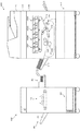
そこで、上述したスタンドアロン型の改質装置100を用いてかかる出力物の表面の改質を行うには、かかる出力物を、トナー像の表面を含むその表面を被加工面として有する被加工物Sとし、図15に示すように、排紙トレイ117上にスタックされた出力物を、被加工物Sとして給送部30にセットして、操作パネル93を操作して、給送部30から改質部10への被加工物Sの給送を開始することとなる。
Therefore, in order to modify the surface of such an output product using the above-described stand-
この改質を行うとき、改質ユニット80の姿勢を、排紙トレイ117上に積載されている被加工物Sの非加工面の向きに合わせて、正位置、逆位置のいずれか適正な方に設定すれば、かかるセットの際の作業性が向上する。これは、画像形成装置200は両面画像形成装置であるため、排紙トレイ117上に積載されている被加工物Sの非加工面が、上を向いている場合と、下を向いている場合とがあるためである。
When this reforming is performed, the proper one of the normal position and the reverse position is set in accordance with the orientation of the reforming
たとえば、改質ユニット80の姿勢に合わせて、排紙トレイ117上に積載されている被加工物Sを反転させて給送部30にセットするとすれば、この反転作業自体に手間がかかるほか、反転の際に被加工物Sの積載状態が崩れた場合には、被加工物Sの整合作業がさらに必要となる。しかしながら、改質ユニット80の姿勢は、正位置、逆位置のいずれにも設定可能であるため、排紙トレイ117上に積載されている被加工物Sをそのままの向きで給送部30にセットすればよく、このセットは単に排紙トレイ117からの積み替えのみで済むため、かかるセットの作業性が良好である。
For example, if the workpiece S loaded on the
図16に示すように、改質装置100は、スタンドアロン型でなく、画像形成装置200において画像形成済みの出力物を被加工物としこの被加工物の後処理を行う、画像形成装置200に着脱可能な後処理装置195に備えられているものであっても良い。この後処理装置195に備えられた改質装置100は、上述の改質装置100と比べ、給送部30を省略されている一方で、通信部192との間で通信を行う通信手段としての通信部92を備えている。また、この改質装置100では、通信部92において、画像形成装置200の出力物である被加工物について、いずれの面を被加工面とすべきかに関する情報、画像形成速度に関する情報が、画像形成装置200側から入力されるようになっている。
画像形成装置200は、上述の画像形成装置200と比べ、排紙トレイ117を省略されている。
As shown in FIG. 16, the
In the
後処理装置195は、画像形成装置200に装着されると、通信部92が通信部192との間で通信可能となる。後処理装置195は、画像形成装置200において画像形成装置が開始されると、その旨が通信部192から通信部92に入力され、改質部10及び排気部20が動作を開始し、また排紙ローラ107によって画像形成装置200から排出された出力物が被加工物として改質装置100に進入し、改質が行われる。
When the
このとき、画像形成装置200における画像形成速度が通信部192から通信部92に入力され、搬送ベルト12の回転速度が画像形成速度に合致するように、モータ18の回転速度が調整される。これによって、後処理装置195において被加工物のジャムが生じることなく且つ速やかに、被加工物の改質が行われる。
At this time, the image forming speed in the
また、被加工物Sのいずれの面を被加工面とすべきかに関する情報を取得に基づき、改質ユニット80の位置決め状態がこれと合致していない場合は、操作パネル93に、その旨の表示を行うことによる警告を行う。
If the positioning state of the reforming
なお、画像形成装置200が、かかる警告が可能な、たとえば操作パネル93における表示部と同様の、表示部を有している場合には、この表示部にかかる警告の表示を行うようにしても良く、この場合には、操作パネル93における表示部を省略可能である。
その他の動作はすでに述べたとおりである。
When the
Other operations are as described above.
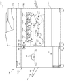
図17に示すように、改質装置100は、画像形成装置200自体に備えられていても良い。この場合、同図に示しているように、定着装置106と排紙トレイ117との間であって、反転装置109への分岐位置よりも定着装置106側に改質部10を組み込み、排気部120を排気部20と共用し、シート給送装置161を給送部30と共用し、排紙トレイ117を積載部40と共用する。このように、画像形成装置200が改質装置100を備え、画像形成済みの出力物を改質装置100における被加工物としその被加工面の改質を改質装置100で行うようにすれば、部品の共用を行うことで部品点数が削減され、低コスト化、小型化において利点がある。この場合も被加工物のいずれの面を被加工面とすべきかに応じて、改質ユニット80の姿勢を、正位置、逆位置の何れかに設定する。またこの場合、画像形成装置200は、たとえば操作パネル93における表示部と同様の、表示部を有しており、この表示部に上述したのと同様に警告の表示を行うようになっている。
As shown in FIG. 17, the
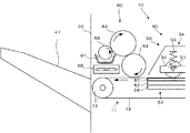
これら各種の改質装置100は、被加工物を改質することで改質された被加工面に、その改質によって可能となった加工を施す加工手段を有していても良い。改質装置100は、疎水性を有する被加工面を親水性に改質する機能を有するため、かかる加工手段としては、疎水性の面には塗工性が低く親水性の面には塗工性が高いニスを塗工するニスコーターが挙げられる。改質装置100がこの加工手段としてのニスコーターを有する例として、図18に、図1又は図16に示した改質装置100が、かかる加工手段としての加工装置であるニスコーター60を有する構成例を示す。
These various reforming
ニスコーター60は、液状のニスを貯容した貯容部61と、貯容部61に一部が浸漬された第1のローラ62と、第1のローラ62に当接し第1のローラ62からニスを塗布される第2のローラ63と、第2のローラ63に当接し第2のローラ63からニスを塗布されるとともに第2のローラ63から塗布されたニスを、搬送ベルト12によって搬送されている被加工物に塗布する第3のローラ64と、被加工物に塗布されたニスを乾かすための乾燥手段としてのファン65とを有している。第3のローラ64は搬送ベルト12あるいはこれによって搬送されている被加工物に連れ回りし、第2のローラ63は第3のローラに連れ回りし、第1のローラ62は第2のローラ63に連れ回りする。
The
このような構成の改質装置100によれば、改質とともに、改質によって可能となった加工を施す一連の処理が連続して行われる。また、ファン65でニスを乾かすことで、積載トレイ41上に積載された被加工物にニスの裏移りが生じることが防止ないし抑制されるとともに、ニスによる被加工面のつやが早期に現れる。
According to the reforming
以上本発明の好ましい実施の形態について説明したが、本発明はかかる特定の実施形態に限定されるものではなく、上述の説明で特に限定していない限り、特許請求の範囲に記載された本発明の趣旨の範囲内において、種々の変形・変更が可能である。 The preferred embodiments of the present invention have been described above. However, the present invention is not limited to the specific embodiments, and the present invention described in the claims is not specifically limited by the above description. Various modifications and changes are possible within the scope of the above.
たとえば、図19に示すように、対向電極部53は、放電電極ローラ51との間でプラズマを発生させるための対向電極としてのカウンター電極として、平板状でなく、ローラ状のカウンター電極ローラ52を有していても良い。この場合、カウンター電極は被加工物の搬送方向において分割されているといえる。カウンター電極ローラ52は各放電電極ローラ51と対を成すように複数備えられている。カウンター電極ローラ52はアルミニウム等の導電性であり、表面を誘電体あるいは絶縁体で被覆されている。カウンター電極ローラ52は、搬送ベルト12に連れ回りする。よって、平板状のカウンター電極52と異なり、搬送ベルト12の摺接が生じないため、搬送ベルト12の負担が軽く、搬送ベルト12が経時的に良好な状態を維持される。この場合、カウンター電極駆動手段は、複数のカウンター電極ローラ52のうちの少なくとも1つを放電電極ローラ51に対して変位する。
For example, as shown in FIG. 19, the
また、改質ユニットは、改質装置内の搬送経路の配設態様によっては、上下反転に限られず、たとえば左右反転したそれぞれの姿勢で位置決めされるものであっても良い。改質ユニットは、回転軸を中心とした回転によって複数の姿勢となる場合であっても、各姿勢で、異なる搬送経路において改質を行うように構成されていても良い。これは、複数の搬送経路が改質装置内に設けられているとともに、回転軸が搬送ベルトによる被加工物の搬送位置とずれて配設されており、回転により異なる搬送経路において改質が可能となるように構成されているような場合である。これらのことは改質装置が、後処理装置内、画像形成装置内に配設される場合も同様である。 Further, the reforming unit is not limited to upside down depending on the arrangement mode of the conveyance path in the reformer, and may be positioned in, for example, left and right inverted positions. The reforming unit may be configured to perform reforming in different transport paths in each posture, even when the posture is in a plurality of postures by rotation about the rotation axis. This is because a plurality of transport paths are provided in the reforming device, and the rotation shaft is arranged so as to be shifted from the transport position of the workpiece by the transport belt, so that reforming can be performed in different transport paths by rotation. It is a case where it is constituted so that. The same applies to the case where the reforming apparatus is disposed in the post-processing apparatus or the image forming apparatus.
改質ユニットは、回転軸を中心とした回転によって複数の姿勢となるのではなく、改質装置内の搬送経路の配設態様によっては、改質装置内の分離した異なる位置でそれぞれ改質可能な姿勢となるように構成されていても良い。たとえば、改質装置に分岐した複数の搬送経路がある場合に、各搬送経路で改質を行うようにするためである。またたとえば、改質装置が、パンチ部、ステープル部を有する後処理装置であって各部が異なる搬送経路に設けられている後処理装置内に備えられている場合において、各部の何れかを通過した被加工物に対して選択的に改質を行うようにする場合である。またたとえば、改質装置が、画像形成装置内に備えられている場合であって、画像形成部の通過前の位置、画像形成部の通過後の位置の何れかを通過する被加工物に対して改質を行うようにする場合である。 The reforming unit can be reformed at different positions in the reforming device depending on the arrangement of the transport path in the reforming device, instead of having multiple postures by rotating around the rotation axis. You may be comprised so that it may become a proper attitude | position. For example, when there are a plurality of transport paths branched into the reformer, reforming is performed on each transport path. Further, for example, when the reforming apparatus is a post-processing apparatus having a punch section and a staple section, and each section is provided in a post-processing apparatus provided in a different transport path, it passes through any of the sections. This is a case in which the work is selectively modified. Further, for example, when the reforming device is provided in the image forming apparatus, the workpiece passes through either the position before passing the image forming unit or the position after passing the image forming unit. In this case, the modification is performed.
本発明にかかる改質装置は、被加工物の種類、たとえば普通紙であるか、薄紙であるか、厚紙であるか、OHPシートであるかを検知する被加工物種検知手段を備え、これを用いて検知した被加工物種情報を用いて、プラズマ制御手段により放電電極に与えるエネルギーを調整し、被加工面に接触するプラズマの強度を制御するようにしても良い。本発明にかかる改質装置は、後処理装置に備えられている場合には、これに備えた通信手段で被加工物種情報その他上述した各種情報を入力されるようにしても良い。本発明にかかる改質装置は、画像形成装置に備えられている場合には、画像形成装置に用いられる情報を被加工物種情報その他上述した各種情報として用いるようにしても良い。本発明にかかる改質装置は、スタンドアロン型であっても通信手段を備えていてもよく、この通信手段をPC、インターネット、LAN等の通信回線に接続可能にして、かかる通信回線からかかる通信手段で被加工物種情報等の上述した各種情報を入力されるようにしても良い。 The reforming apparatus according to the present invention includes a workpiece type detecting means for detecting the type of workpiece, for example, plain paper, thin paper, thick paper, or an OHP sheet. By using the workpiece type information detected by use, the energy applied to the discharge electrode by the plasma control means may be adjusted to control the intensity of the plasma contacting the workpiece surface. When the reforming apparatus according to the present invention is provided in the post-processing apparatus, the workpiece type information and other various types of information described above may be input by a communication means provided for the reforming apparatus. When the image forming apparatus is equipped with the reforming apparatus according to the present invention, information used for the image forming apparatus may be used as the workpiece type information and other various information described above. The reforming apparatus according to the present invention may be a stand-alone type or provided with a communication means. The communication means can be connected to a communication line such as a PC, the Internet, or a LAN, and the communication means is connected to the communication line. The above-described various information such as workpiece type information may be input.
また、上述の各形態では、放電電極が被加工物に当接するように構成されているが、放電電極は被加工物からたとえば50μm程度の微少距離だけ離間する位置に配設されていても良い。放電電極が被加工物から離間していれば、たとえば被加工物が転写紙である場合にこの転写紙に付着している紙粉が放電電極に付着して放電電極の性能が低下するなど、被加工物に付着している汚れが放電電極に付着して放電電極の性能が低下することが防止ないし抑制される。ただし、放電電極が被加工物から離間している構成では、放電電極とカウンターとの距離が大きくなるため、エネルギーの損失が生じるとともに、沿面放電を阻害する要因ともなるため、この距離は、できるだけ小さいほうが好ましい。なお、放電電極の放電による偏磨耗を低減するためや、沿面放電やプラズマを形成する部位を変化させ被加工面の改質の均一性を向上するために、放電電極を被加工物から離間させた構成においても、放電電極を回転させるのが好ましい。 In each of the above embodiments, the discharge electrode is configured to contact the workpiece. However, the discharge electrode may be disposed at a position separated from the workpiece by a minute distance of, for example, about 50 μm. . If the discharge electrode is separated from the workpiece, for example, when the workpiece is transfer paper, the paper powder attached to the transfer paper adheres to the discharge electrode, and the performance of the discharge electrode decreases. It is prevented or suppressed that dirt adhering to the workpiece adheres to the discharge electrode and deteriorates the performance of the discharge electrode. However, in the configuration in which the discharge electrode is separated from the work piece, the distance between the discharge electrode and the counter becomes large, so that energy loss occurs and becomes a factor that inhibits creeping discharge. Smaller is preferable. In order to reduce uneven wear due to the discharge of the discharge electrode or to improve the uniformity of the modification of the work surface by changing the surface discharge or plasma formation site, the discharge electrode is separated from the work piece. Even in such a configuration, it is preferable to rotate the discharge electrode.
本発明を適用した改質装置を有する画像形成装置あるいは本発明を適用した改質装置の被加工物となる出力物を形成する画像形成装置は、図14に示して説明したようないわゆるタンデム方式の画像形成装置ではなく、1つの感光体ドラム上に順次各色のトナー像を形成して各色トナー像を順次重ね合わせてカラー画像を得るいわゆる1ドラム方式の画像形成装置であっても良い。また、カラー画像形成装置でなく、モノクロ画像形成装置にも本発明を適用可能である。いずれのタイプの画像形成装置でも、中間転写体を用いず、各色のトナー像を転写紙等に直接転写しても良い。ただし、ワックス含有トナーを用いる画像形成装置においては、カラー画像を得る等のためにトナー像を重ね合わせたほうが疎水性が高くなるため、改質を行うことによる効用は高い。 An image forming apparatus having a reforming apparatus to which the present invention is applied or an image forming apparatus for forming an output product to be processed by the reforming apparatus to which the present invention is applied is a so-called tandem method as shown in FIG. Instead of the image forming apparatus, a so-called one-drum type image forming apparatus that sequentially forms toner images of the respective colors on one photosensitive drum and sequentially superimposes the color toner images to obtain a color image may be used. Further, the present invention can be applied not only to a color image forming apparatus but also to a monochrome image forming apparatus. In any type of image forming apparatus, a toner image of each color may be directly transferred onto a transfer sheet or the like without using an intermediate transfer member. However, in an image forming apparatus using a wax-containing toner, superimposing toner images to obtain a color image or the like becomes more hydrophobic, so that the effect of performing the modification is high.
本発明を適用した改質装置を有する後処理装置は、改質され出力される被加工物の揃え機能、パンチ機能、ステープル機能等を有していても良い。ステープル機能は、上述のような加工手段を有し加工手段による加工を経た被加工物をステープルするように備えられていることが好ましい。 The post-processing apparatus having the reforming apparatus to which the present invention is applied may have a function of aligning a workpiece to be reformed and output, a punch function, a staple function, and the like. The stapling function is preferably provided so as to staple the workpiece having the processing means as described above and processed by the processing means.
改質は、均一に行われる等の所望の状態で行われるのであれば、ベルトによる被加工物の搬送を停止した状態、間欠的に行っている状態で、実施してもよい。
ベルトの支持は、上述の2つの支持部材のみによって行うのに限らず、かかる2つの支持部材によってベルトに平面部分が形成されるのであれば、かかる2つの支持部材とは別の支持部材を加えてベルトの支持を行っても良い。この別の支持部材は、ローラでなく、固定の部材であってもよい。
If the modification is performed in a desired state such as being performed uniformly, the modification may be performed in a state where the conveyance of the workpiece by the belt is stopped or intermittently performed.
The support of the belt is not limited to the above-described two support members. If a flat portion is formed on the belt by the two support members, a support member different from the two support members is added. The belt may be supported. This another support member may be a fixed member instead of a roller.
本発明の実施の形態に記載された効果は、本発明から生じる最も好適な効果を列挙したに過ぎず、本発明による効果は、本発明の実施の形態に記載されたものに限定されるものではない。 The effects described in the embodiments of the present invention are only the most preferable effects resulting from the present invention, and the effects of the present invention are limited to those described in the embodiments of the present invention. is not.
11 搬送手段
12 ベルト
12a 平面部分
13、14 2つの支持部材、テンション付与部材
17 駆動手段
33 検知手段
34b 排出口
35a、35b 複数の吸引口
36 キャップ部
38 回転軸
45 位置決め手段
45a 位置決め部材
51 放電電極
80 改質ユニット
100 改質装置
195 後処理装置
200 画像形成装置
S 被加工物
DESCRIPTION OF
Claims (11)
この改質ユニットを複数の位置で位置決めし同改質ユニットにより複数の位置で前記被加工面の改質を可能とするための位置決め手段とを有する改質装置。 Conveying means for conveying the workpiece, and plasma that is disposed opposite to the conveying means and that contacts the workpiece surface of the workpiece to modify the workpiece surface is applied to the workpiece surface. A reforming unit comprising a discharge electrode for forming
A reforming apparatus comprising positioning means for positioning the reforming unit at a plurality of positions and allowing the reforming unit to modify the work surface at a plurality of positions.
前記搬送手段は、被加工物を搬送するために移動するベルトと、このベルトを支持した2つの支持部材とを有し、
前記ベルトは、前記2つの支持部材の間で張り渡されている平面部分に前記放電電極を対向配置されており、
前記2つの支持部材のうち、前記ベルトの移動方向において前記平面部分の上流側の支持部材は、同ベルトに張力を与えるテンション付与部材であるとともに、前記ベルトの移動方向において前記平面部分の下流側の支持部材は、同ベルトを前記移動方向に移動させるために回転駆動される駆動ローラであり、
前記ベルトを前記移動方向に移動させるために前記下流側の支持部材と連結され同支持部材を回転駆動する駆動手段を有し、
前記位置決め手段は、前記下流側の支持部材を、前記駆動手段と連結される連結位置に位置決めする位置決め部材を備えていることを特徴とする改質装置。 The reformer according to claim 1, wherein
The transport means includes a belt that moves to transport the workpiece, and two support members that support the belt,
The belt is arranged so that the discharge electrode is opposed to a plane portion that is stretched between the two support members,
Of the two support members, the support member on the upstream side of the planar portion in the moving direction of the belt is a tension applying member that applies tension to the belt, and the downstream side of the planar portion in the moving direction of the belt. The support member is a drive roller that is rotationally driven to move the belt in the moving direction.
Drive means coupled to the downstream support member for rotationally driving the support member to move the belt in the moving direction;
The said positioning means is provided with the positioning member which positions the said downstream support member in the connection position connected with the said drive means, The reformer characterized by the above-mentioned.
前記2つの支持部材は、ともに前記テンション付与部材であり、
前記改質ユニットが前記位置決め手段によって位置決めされた位置に応じて、前記2つの支持部材の何れか一方が、前記位置決め部材によって前記連結位置に位置決めされ、前記駆動手段と連結されて前記駆動ローラとなることを特徴とする改質装置。 The reformer according to claim 2, wherein
The two support members are both the tension applying members,
Depending on the position where the reforming unit is positioned by the positioning means, either one of the two support members is positioned at the connection position by the positioning member, and is connected to the drive means to the drive roller. A reformer characterized by comprising:
前記位置決め手段は、前記平面部分上の被加工物が同一位置を占めるように前記改質ユニットが反転するそれぞれの位置で、同改質ユニットを位置決め可能であることを特徴とする改質装置。 The reformer according to any one of claims 1 to 3,
The reforming apparatus characterized in that the positioning means can position the reforming unit at each position where the reforming unit is inverted so that the workpieces on the plane portion occupy the same position.
前記それぞれの位置において、前記搬送手段による被加工物の搬送方向が逆転されることで、前記改質ユニットにおける被加工物の搬送方向を保つことを特徴とする改質装置。 The reformer according to claim 4, wherein
The reforming apparatus characterized in that the transport direction of the workpiece in the reforming unit is maintained by reversing the transport direction of the workpiece by the transport means at the respective positions.
前記駆動ローラと平行に設けられ、前記改質ユニットを回転可能に支持した回転軸を有し、
前記位置決め部材は、前記改質ユニットが前記回転軸を中心に回転されるときに、前記下流側の支持部材に当接することで、同改質ユニットの回転を規制することを特徴とする改質装置。 The reformer according to any one of claims 1 to 5, wherein the reformer is dependent on the reformer according to claim 2.
A rotation shaft provided in parallel with the drive roller and rotatably supporting the reforming unit;
The positioning member restricts rotation of the reforming unit by contacting the downstream support member when the reforming unit is rotated about the rotation shaft. apparatus.
前記改質ユニットは、前記放電電極によって前記プラズマを形成することで生じたオゾンを排出するための排出口を備えており、
前記改質ユニットが前記位置決め手段によって位置決めされた位置に応じて、前記排出口に選択的に連結され、前記オゾンを吸引する複数の吸引口を有することを特徴とする改質装置。 The reformer according to any one of claims 1 to 6,
The reforming unit includes a discharge port for discharging ozone generated by forming the plasma by the discharge electrode,
A reformer having a plurality of suction ports that are selectively connected to the discharge port and suck the ozone according to a position where the reforming unit is positioned by the positioning means.
前記改質ユニットは、前記複数の吸引口のうち、前記排出口と連結された吸引口と異なる吸引口を塞ぐためのキャップ部を備えていることを特徴とする改質装置。 The reformer according to claim 7, wherein
The reforming unit includes a cap unit for closing a suction port different from a suction port connected to the discharge port among the plurality of suction ports.
前記位置決め手段による前記改質ユニットの位置決め状態を検知する検知手段を有することを特徴とする改質装置。 The reformer according to any one of claims 1 to 8,
A reforming apparatus comprising a detecting means for detecting a positioning state of the reforming unit by the positioning means.
Priority Applications (1)
| Application Number | Priority Date | Filing Date | Title |
|---|---|---|---|
| JP2011111769A JP2012242558A (en) | 2011-05-18 | 2011-05-18 | Modification device, post-processing device and image formation device |
Applications Claiming Priority (1)
| Application Number | Priority Date | Filing Date | Title |
|---|---|---|---|
| JP2011111769A JP2012242558A (en) | 2011-05-18 | 2011-05-18 | Modification device, post-processing device and image formation device |
Publications (1)
| Publication Number | Publication Date |
|---|---|
| JP2012242558A true JP2012242558A (en) | 2012-12-10 |
Family
ID=47464346
Family Applications (1)
| Application Number | Title | Priority Date | Filing Date |
|---|---|---|---|
| JP2011111769A Withdrawn JP2012242558A (en) | 2011-05-18 | 2011-05-18 | Modification device, post-processing device and image formation device |
Country Status (1)
| Country | Link |
|---|---|
| JP (1) | JP2012242558A (en) |
Cited By (2)
| Publication number | Priority date | Publication date | Assignee | Title |
|---|---|---|---|---|
| JP2018536459A (en) * | 2015-11-11 | 2018-12-13 | ホーホシューレ フュア アンゲヴァンテ ヴィッセンシャフト ウント クンスト ヒルデスハイム/ホルツミンデン/ゲッティンゲン | Method and apparatus for hand drying and plasma-based disinfection |
| JP2021103265A (en) * | 2019-12-25 | 2021-07-15 | キヤノン株式会社 | Image forming system |
-
2011
- 2011-05-18 JP JP2011111769A patent/JP2012242558A/en not_active Withdrawn
Cited By (3)
| Publication number | Priority date | Publication date | Assignee | Title |
|---|---|---|---|---|
| JP2018536459A (en) * | 2015-11-11 | 2018-12-13 | ホーホシューレ フュア アンゲヴァンテ ヴィッセンシャフト ウント クンスト ヒルデスハイム/ホルツミンデン/ゲッティンゲン | Method and apparatus for hand drying and plasma-based disinfection |
| JP2021103265A (en) * | 2019-12-25 | 2021-07-15 | キヤノン株式会社 | Image forming system |
| JP7451173B2 (en) | 2019-12-25 | 2024-03-18 | キヤノン株式会社 | image forming system |
Similar Documents
| Publication | Publication Date | Title |
|---|---|---|
| JP5370033B2 (en) | Reforming apparatus, post-processing apparatus, and image forming apparatus | |
| US8843015B2 (en) | Imaging device, image forming apparatus, and process cartridge | |
| JP2011060737A (en) | Reforming device, post-treatment apparatus, and picture forming apparatus | |
| JP5125151B2 (en) | Fixing device and image forming apparatus using the same | |
| JP2010237451A (en) | Image forming apparatus | |
| JP5463951B2 (en) | Image forming apparatus | |
| JP5493621B2 (en) | Reforming apparatus, post-processing apparatus, and image forming apparatus | |
| JP5914986B2 (en) | Reforming apparatus, post-processing apparatus, and image forming apparatus | |
| JP2008310241A (en) | Image forming apparatus | |
| US8862045B2 (en) | Conveyor and image forming apparatus with the conveyor | |
| JP2006001686A (en) | RECORDER CONVEYING DEVICE AND IMAGE FORMING DEVICE | |
| JP5531946B2 (en) | Reforming apparatus and image forming apparatus | |
| JP4340524B2 (en) | Image forming apparatus | |
| JP2005352401A (en) | Image forming apparatus | |
| JP2013020138A (en) | Discharge device and image forming apparatus | |
| JP2012246070A (en) | Recording medium conveying device and image forming apparatus | |
| JP2012099360A (en) | Reformer and post-processing device and image forming device | |
| JP2012123323A (en) | Image forming apparatus and modifying device | |
| JP4496071B2 (en) | Recording paper transport device and image forming apparatus | |
| JP7387988B2 (en) | Developer container and image forming device | |
| JP2006251371A (en) | Image forming apparatus | |
| JP2005266220A (en) | Image forming apparatus and image forming method | |
| JP2005189607A (en) | Image forming apparatus | |
| US11526095B2 (en) | Image forming apparatus including detachable development device | |
| JP2006085016A (en) | Image forming apparatus |
Legal Events
| Date | Code | Title | Description |
|---|---|---|---|
| A711 | Notification of change in applicant |
Free format text: JAPANESE INTERMEDIATE CODE: A711 Effective date: 20130423 |
|
| RD03 | Notification of appointment of power of attorney |
Free format text: JAPANESE INTERMEDIATE CODE: A7423 Effective date: 20130621 |
|
| A300 | Withdrawal of application because of no request for examination |
Free format text: JAPANESE INTERMEDIATE CODE: A300 Effective date: 20140805 |