JP2012242586A - Display device - Google Patents
Display device Download PDFInfo
- Publication number
- JP2012242586A JP2012242586A JP2011112282A JP2011112282A JP2012242586A JP 2012242586 A JP2012242586 A JP 2012242586A JP 2011112282 A JP2011112282 A JP 2011112282A JP 2011112282 A JP2011112282 A JP 2011112282A JP 2012242586 A JP2012242586 A JP 2012242586A
- Authority
- JP
- Japan
- Prior art keywords
- display
- image
- display device
- displayed
- axis
- Prior art date
- Legal status (The legal status is an assumption and is not a legal conclusion. Google has not performed a legal analysis and makes no representation as to the accuracy of the status listed.)
- Withdrawn
Links
- 230000007246 mechanism Effects 0.000 claims abstract description 27
- 238000006073 displacement reaction Methods 0.000 claims abstract description 20
- 238000005401 electroluminescence Methods 0.000 description 6
- 238000013459 approach Methods 0.000 description 4
- 238000010586 diagram Methods 0.000 description 4
- 230000000694 effects Effects 0.000 description 4
- 239000000446 fuel Substances 0.000 description 3
- 230000009471 action Effects 0.000 description 2
- 230000008859 change Effects 0.000 description 2
- 238000000034 method Methods 0.000 description 2
- 230000002093 peripheral effect Effects 0.000 description 2
- 230000001186 cumulative effect Effects 0.000 description 1
- 238000009434 installation Methods 0.000 description 1
- 238000012544 monitoring process Methods 0.000 description 1
- 230000004044 response Effects 0.000 description 1
- 230000000007 visual effect Effects 0.000 description 1
Images


Landscapes
- Projection Apparatus (AREA)
- Instrument Panels (AREA)
- Devices For Indicating Variable Information By Combining Individual Elements (AREA)
Abstract
Description
本発明は、奥行き感を持たせた表示が可能な表示装置に関する。 The present invention relates to a display device capable of displaying with a sense of depth.
奥行き感のある表示を行う従来の表示装置の一つとして、特許文献1に記載のものが知られている。この表示装置では、第1表示器にて表示する情報をハーフ・ミラーで反射してその虚像をユーザーに見せるとともに、実像にて情報を表示する第2表示器を第1表示器の後ろ位置で後方に向けて傾斜させ、この中途位置が虚像の中途位置で横から見てX字状に交差するようにすることにより、虚像の中途位置より上方の部分が実像の中途位置より上方の部分に対し奥側に見え、虚像の中途位置より下方の部分が実像の中途位置より下方の部分に対し手前側に見えるようにしている。
As one of conventional display devices that perform display with a sense of depth, a device described in
また、別の従来のこの種の表示装置として、特許文献2に記載のものが知られている。この表示装置では、スピード・メータ等の基本機能をアナログ表示する2個のアナログメータ部の中間位置の手前で、これらのアナログメータ部に重なる形で表示内容が視認可能となるように有機EL(Electroluminescence)ディスプレイ等からなる表示器が配置されるとともに、この表示器自身をこの表示面と平行に配置した回転軸周りに回転移動させる表示器進退機構が設けられ、表示画像に応じて表示器を視認方向の前側または後側に傾斜させた状態にすることで、表示面の上下に遠近感を持たせるようにしている。また、表示器で警告表示することもでき、その場合、表示器は直立動作させられる。
Further, another conventional display device of this type is known from
しかしながら、上記従来の表示装置には、それぞれ以下に説明するような問題がある。
まず、前者の従来装置にあっては、虚像が常に前後に傾いた状態、すなわち上方側は下側より遠方で小さく見える状態で表示されるため、前方を走行している車両の像を表示するような場合には自然に見えるものの、走行距離の表示等にあっては表示部分が上になるほど像が小さくなることから、このような表示は自然ではなく、また必然性もないので、ドライバ等のユーザーによっては違和感が生じることがある。このように、前者の従来装置では、表示内容に合わせて違和感がなく表示できる表示の種類がかなり限られてしまうといった問題がある。
However, the conventional display devices have problems as described below.
First, in the former conventional device, the virtual image is always displayed in a state of being tilted back and forth, that is, the upper side appears smaller than the lower side, so an image of a vehicle traveling ahead is displayed. In such a case, it looks natural, but in the display of mileage etc., the image becomes smaller as the display part goes up, so such a display is not natural and is not necessarily necessary. Some users may feel uncomfortable. As described above, the former conventional apparatus has a problem that the types of display that can be displayed without a sense of incongruity according to the display contents are considerably limited.
一方、後者の従来装置にあっては、表示器の表示面が平面であり表示器を傾斜させるだけなので、その表示はたとえば地図上の地表の一部を俯瞰的に切り出すような表示内容だけに限られてしまう。また、警告時のときの表示のように、表示器の回転動作をつけて強調するが、そのため表示に傾斜を付け過ぎた状態では表示内容が視認しづらく、またそのような警告のための回転動作といった挙動ではユーザーになじみが薄く、その意図が伝わりにくい。このように、後者の従来装置でも、表示内容に合わせて違和感がなく表示できる表示の種類がかなり限られてしまうといった問題もある。 On the other hand, in the latter conventional device, since the display surface of the display device is a flat surface and the display device is only tilted, the display is limited to display contents that cut out a part of the ground surface on a map, for example. It will be limited. Also, like the display at the time of warning, the display is rotated and emphasized. However, if the display is tilted too much, it is difficult to see the display content. The behavior, such as movement, is unfamiliar to the user and the intention is difficult to convey. Thus, the latter conventional device also has a problem that the types of display that can be displayed without a sense of incongruity in accordance with the display contents are considerably limited.
本発明は、上記問題に着目してなされたもので、その目的とするところは、奥行き感がより自然に出せ、かつ表示内容に合わせて違和感がなく、かつ表示内容の理解が容易となる表示の種類をより多く得ることが可能な表示装置を提供することにある。 The present invention has been made paying attention to the above-mentioned problems, and the purpose of the present invention is to provide a display that can provide a more natural feeling of depth, no discomfort according to the display contents, and easy understanding of the display contents. An object of the present invention is to provide a display device that can obtain a larger number of types.
この目的のため、請求項1に記載の本発明による表示装置は、
ユーザーが実像を視認可能な第1表示装置と、
この第1表示装置の実像とは異なる表示内容を表示可能な第2表示器と、
第1表示装置と第2表示器との間に配置されて、第1表示装置の実像を透過し、かつ表示器に表示された表示内容を反射してこの反射方向とは逆方向の位置に像を形成し、実像と像をユーザーに見せるハーフ・ミラーと、
第2表示器の奥側端部分および手前側端部分のそれぞれの位置をハーフ・ミラーに対し独立して変位させることが可能な表示器変位機構と、
備えたことを特徴とする。
For this purpose, a display device according to the invention as claimed in
A first display device that allows a user to visually recognize a real image;
A second display capable of displaying display content different from the real image of the first display device;
It is disposed between the first display device and the second display device, transmits the real image of the first display device, reflects the display content displayed on the display device, and is in a position opposite to the reflection direction. A half mirror that forms an image and shows the real image and the image to the user;
A display displacement mechanism capable of independently displacing each position of the back side end portion and the front side end portion of the second display with respect to the half mirror;
It is characterized by having.
また、請求項2に記載の本発明による表示装置は、
請求項1に記載の表示装置において、
表示器変位機構が、
第2表示器の奥側端部分に取り付けられた第1アーム付きリンクと、
第2表示器の手前端側位置に取り付けられた第2アーム付きリンクと、
第1アーム付きリンクを回転駆動可能な第1アクチュエータと、
第2アーム付きリンクを回転駆動可能な第2アクチュエータと、
を有することを特徴とする。
A display device according to the present invention described in
The display device according to
The display displacement mechanism
A link with a first arm attached to the back end portion of the second indicator;
A link with a second arm attached to the front end side position of the second indicator;
A first actuator capable of rotationally driving the link with the first arm;
A second actuator capable of rotationally driving the link with the second arm;
It is characterized by having.
また、請求項3に記載の本発明による表示装置は、
請求項1又は請求項2に記載の表示装置において、
表示器変位機構が、像を第1表示装置による実像の手前、奥側へ変位可能である、
ことを特徴とする。
A display device according to the present invention described in
The display device according to
The display displacement mechanism is capable of displacing the image to the front side and the back side of the real image by the first display device.
It is characterized by that.
また、請求項4に記載の本発明による表示装置は、
請求項1乃至3のいずれか1項に記載の表示装置において、
表示器変位機構が、像を第1表示装置による実像に対し手前、奥側へ傾斜可能である、
ことを特徴とする。
A display device according to the present invention described in claim 4
The display device according to any one of
The display displacement mechanism is capable of tilting the image toward the front and back with respect to the real image by the first display device.
It is characterized by that.
また、請求項5に記載の本発明による表示装置は、
表示器変位機構が、像を手前、奥側へ凸となる曲面上に表示可能である、
であることを特徴とする。
A display device according to the present invention described in
The display displacement mechanism can display the image on a curved surface that is convex toward the front and back.
It is characterized by being.
請求項1に記載の本発明の表示装置にあっては、像の位置を実像に対し手前側、奥側に移動可能となり、また像の表示を傾斜、変形させることができるようになる結果、奥行き感がより自然に出せ、かつ表示内容に合わせて違和感がなく、かつ表示内容の理解が容易となる表示の種類を多く得ることが可能となる。 In the display device according to the first aspect of the present invention, the position of the image can be moved to the near side and the far side with respect to the real image, and the display of the image can be tilted and deformed. It is possible to obtain many types of display that can give a sense of depth more naturally, have no sense of incongruity according to the display contents, and facilitate understanding of the display contents.
また、請求項2に記載の本発明の表示装置にあっては、種々の表示を可能とするように、また表示の形状を変えることができるようにするための第2表示器の変位を、簡単な機構で容易に実行することができる。
In the display device of the present invention according to
また、請求項3に記載の本発明の表示装置にあっては、像を実像の手前、奥側の位置に見せること、また手前〜奥側間で像を移動させながら表示することが可能となり、表示内容に合った表示の形態の選択肢を増やすことが可能となる。 In the display device according to the third aspect of the present invention, it is possible to display an image at a position before and behind the real image and to display while moving the image between the front and back sides. Thus, it is possible to increase the number of display format options that match the display content.
また、請求項4に記載の本発明の表示装置にあっては、像を第1表示装置による実像に対し手前、奥側へ傾斜させて奥行きある表示を可能となり、表示内容に合った表示の形態の選択肢を増やすことが可能となる。 In the display device according to the fourth aspect of the present invention, the display can be displayed with a depth by tilting the image toward the front and the back with respect to the real image by the first display device. It becomes possible to increase the choices of the form.
また、請求項5に記載の本発明の表示装置にあっては、像を手前あるいは奥側へ凸となる曲面上に表示することで、より奥行きのある表示が可能となり、また狭い表示エリア内に多くの情報をそれらの位置関係が分かりやすくした状態で表示することが可能となり、表示内容に合った表示の形態の選択肢を増やすことが可能となる。 In the display device according to the fifth aspect of the present invention, an image can be displayed on a curved surface that protrudes toward the front or the back, thereby enabling a deeper display, and in a narrow display area. In addition, it is possible to display a large amount of information in a state in which the positional relationship is easy to understand, and it is possible to increase the number of display format options that match the display contents.
以下、本発明の実施の形態を、図面に示す実施例に基づき詳細に説明する。なお、以下の実施例において同じ構成のものについては同じ番号を付し、それらの説明を省略する。 Hereinafter, embodiments of the present invention will be described in detail based on examples shown in the drawings. In addition, the same number is attached | subjected about the thing of the same structure in a following example, and those description is abbreviate | omitted.
まず、本発明に係る実施例1の表示装置の構成を説明する。
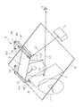
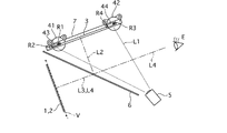
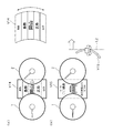
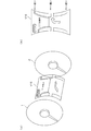
この実施例1の表示装置は、自動車のインストメント・パネルに設けられ、図1および図2に示すように、第1メータ装置1と、第2メータ装置2と、表示器3と、表示器変位機構4と、プロジェクタ5と、ハーフ・ミラー6と、を備え、ドライバに車両情報等の種々の情報を与えるものである。なお、同図中、ドライバの目の位置をEで示してある。
First, the configuration of the display device according to the first embodiment of the present invention will be described.
The display device according to the first embodiment is provided on an instrument panel of an automobile. As shown in FIGS. 1 and 2, a
第1メータ装置(本発明の第1表示装置に相当)1は、エンジンの回転速度を表示するタコ・メータであって、エンジンの回転速度の数字や目盛等を記載した文字盤上を指針が動き、エンジン回転速度に対応する目盛位置を指す。第2メータ装置(本発明の第1表示装置に相当)2は、第1メータ装置1の横方向(車両幅方向)へ所定距離離した位置に配置されたスピード・メータであって、車速の数字や目盛等を記載した文字盤上を指針が動き、車速に対応する目盛を指す。なお、これら第1メータ装置1および第2メータ装置2にあっては、図を見やすくするため、文字盤の数字、文字、目盛等は省略してある。
The first meter device (corresponding to the first display device of the present invention) 1 is a tachometer that displays the engine speed, and the pointer is on the dial on which the engine speed numbers and scales are written. The scale position corresponding to the movement and engine speed. The second meter device (corresponding to the first display device of the present invention) 2 is a speed meter arranged at a position separated by a predetermined distance in the lateral direction (vehicle width direction) of the
表示器(本発明の第2表示装置に相当)3は、この下面に表示画像を表示可能で、かつ弾性変形可能なスクリーンで構成され、第1メータ装置1と第2メータ装置2との間の上方位置に配置されている。スクリーンは、後で詳しく説明するが、平面を保ったり、あるいは上に凸あるいは下に凸となる半弧状の曲面になったりして形状変化することが可能であり、さらにその傾斜角が可変であり、その姿勢を変化することも可能である。
The display (corresponding to the second display device of the present invention) 3 is composed of a screen that can display a display image on its lower surface and is elastically deformable, and is provided between the
表示器変位機構4は、表示器3を変形、変位させるための機構であって、それぞれ電気モータで構成された前方配置の第1アクチュエータ41および後方配置された第2アクチュエータ42と、第1アクチュエータ41により回転駆動される第1アーム付きリンク43と、第2アクチュエータ42により回転駆動される第2アーム付きリンク44と、フレーム7(図1では内側が見えて理解しやすいようにするため省略してあり、図2を参照)と、を有する。
The display device displacement mechanism 4 is a mechanism for deforming and displacing the
第1アクチュエータ1と第2アクチュエータ2とは、図示しない制御器に接続され、表示内容に応じて、後述するように、それぞれ独立して回転させられる。これらのアクチュエータ1、2は、インストルメント・パネル側にフレーム7を介して固定され、それら出力軸がそれぞれ第1軸線R1、第2軸線周りに回転可能にされている。第1軸線R1および第2軸線R2は、いずれも第1、第2メータ装置1、2およびハーフ・ミラー6の上方で、それぞれ車両前後に離間した位置で、車両幅方向に沿う。
第1軸線R1上には、第1アーム付きリンク43の一端側の開口先端部分に固定された第1アクチュエータ41の出力軸と、第1アーム付きリンク43の他端側の開口先端部分に固定された第1軸41aと、が配置される。
同様に、第2軸線R2上には、第2アーム付きリンク44の一端側の開口先端部分に固定された第2アクチュエータ42の出力軸と、第2アーム付きリンク44の他端側の開口先端部分に固定された第2軸42aと、が配置される。
The
On the first axis R1, the output shaft of the
Similarly, on the second axis R2, the output shaft of the
第1アーム付きリンク43および第2アーム付きリンク44は、コ字状に形成されて、それぞれ第1軸線R1周りおよび第2軸線R2周りに回転可能とされている。すなわち、第1アーム付きリンク43の幅方向に離れた両方の開口基部側部分には、表示器3の奥側端部分に設けた軸(第3軸線R3を通る)が回動可能に取り付けられる。
同様に、第2アーム付きリンク44の両方の開口基部側部分には、表示器3の手前側端部分に設けられた軸(第4軸線R4を通る)が回動可能に取り付けられている。
この構成により、第3軸線R3は第1軸線R1周りに第1アクチュエータ41にて回動させることができ、また第4軸線R4は第2軸線R2周りに第2アクチュエータ42にて回動させることが可能である。
The first arm-attached
Similarly, a shaft (passing through the fourth axis R4) provided at the front side end portion of the
With this configuration, the third axis R3 can be rotated around the first axis R1 by the
プロジェクタ5は、本実施例ではレーザ・プロジェクタであって、制御器からの信号に応じて表示内容の画像を作り出し、この画像を表示器3の下面に設けた表示面に投影する。プロジェクタ5で作成される画像は、表示器3の姿勢状態、変形状態に応じて、また表示内容のどこを強調するか、どのような形状でどの位置に表示するか(これらの例は後で詳しく説明する)、といったことに合わせて造り出される。すなわち、表示器3が傾斜していたり曲面になっていたりして表示器3の投影映像が歪む場合には、この表示のひずみは表示面3の状態に応じて制御器であらかじめ演算しその結果に応じてプロジェクタ5から投影することで補正することが可能である。
The
この場合、プロジェクタ5の映像は、画素数相当のレーザ光がそれぞれ直進して表示器3およびハーフ・ミラー6での反射で表示をみることになるので、投影像の焦点合わせは不要となり、投影面が斜めに傾いていてもそれぞれの画素をぼやけることなく表示することができ、その結果、像Vがぼやけることもない。
また、
In this case, the image of the
Also,
ハーフ・ミラー6は、反射光と透過光の強さがほぼ1:1となる平面状の周知のもので、第1メータ装置1および第2メータ装置2の上方位置から手前側へ第1メータ装置1および第2メータ装置2の下端位置の高さ付近まで下方傾斜され、その幅がドライバからみて第1メータ装置1および第2メータ装置2の全範囲をカバーする大きさとする。
The
このハーフ・ミラー6を用いることで、ドライバは、ハーフ・ミラー6を通して第1メート装置1と第2メータ装置2の実像を同時に見ることができる。
一方、プロジェクタ5から第1線L1に沿って表示器3に向けて表示内容を表すレーザ光が投射されると、表示器3上の表示光は、第2線L2に沿って下方に向かい、ハーフ・ミラー6の表面に当たって反射されドライバに第4線L4上の虚像Vとして見えるようになる。
By using the
On the other hand, when laser light representing the display content is projected from the
この反射はハーフ・ミラー6がミラーとして作用するためで、表示器3からハーフ・ミラー6へ入射位置まで第2線L2に沿って光が進む距離は、ハーフ・ミラー6への表示光の入射位置からハーフ・ミラー6の裏面(車両前方側)に見える像Vの位置までの第3線L3に沿った距離に等しくなる。なお、表示光は、第3線L3に沿って実際に進むわけではなく、ドライバにとって第3線L3に重なる第4線L4(図1では説明上ずらして描いてある)上にミラー効果による虚像として見えることになる。
This reflection is because the
したがって、図1では、第1線L1から第4線L4のうち、実際の光が通る第1線L1、第2線L2、第4線L4のハーフ・ミラー6より手前側の部分をそれぞれ実線で、また実際には光が通らない第3線L3を点線で、また第1、第2メータ装置1、2からの光だけが通る第4線L4のハーフ・ミラー6より奥側の部分を2点鎖線で描いてある。なお、図2以降の図では、第1線L1〜第4線L4はすべて1点鎖線で描いてある。
Therefore, in FIG. 1, of the first line L1 to the fourth line L4, the first line L1, the second line L2, and the fourth line L4 on the front side of the
表示器3がドライバからみて、車両幅方向で第1メータ装置1と第2メータ装置2との間に配置されているため、ドライバには、像Vが第1メータ装置1と第2メータ装置2との間で車両前方側すなわち、ハーフ・ミラー6の奥側に見える。このとき、上述したように、第1メータ装置1および第2メータ装置2でのダイアル表示が像Vの左右に同時に一部重なった状態で見えることになる。
Since the
また、表示器3の位置を移動させて、ここから表示器3の表示光がハーフ・ミラー6に当たる入射位置まで第2線L2に沿って進む距離を変化させると、これに応じてハーフ・ミラー6への入射位置から像Vまでの第3線に沿った距離が変化する。これらの距離は、ミラー効果により常に等しくなる。
すなわち、表示器3をハーフ・ミラー6に対し変位させることでそれら間の距離を変化させると、この変化に応じて像Vが第1メータ装置1と第2メータ装置2のダイアル表示位置(本発明の実像位置に相当)に対し前後した位置に見えることとなる。なお、図1では、像Vが第1メータ装置1、第2メータ装置2とほぼ同じ前後位置にある状態を示している。
Further, when the position of the
That is, when the distance between them is changed by displacing the
次に、上記実施例1の表示装置の作用について添付の図とともに説明する。
表示装置により第1、第2のメータ装置ハーフ・ミラー6による実像と、表示器3およびハーフ・ミラー6による虚像とが同時に見えるようになる仕組みは上記で説明したので、以下は、虚像の表示位置を変位させる作用、表示形状の変化させる作用を中心に説明する。
Next, the operation of the display device according to the first embodiment will be described with reference to the accompanying drawings.
Since the mechanism by which the real image by the first and second meter
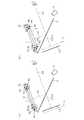
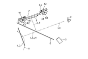
まず、図3(a)に示すように、像Vが第1、第2のメータ装置のダイアル表示位置よりさらに奥に見えるように表示するには、第1アクチュエータ41および第2アクチュエータ42により、第1アーム付きリンク43および第2アーム付きリンク44を第1軸線R1、第2軸線R2周りに同時回転駆動して、第3軸線R3と第4軸線R4とが両方とも最上位置にくるようにする。
First, as shown in FIG. 3A, in order to display the image V so that it can be seen further behind the dial display positions of the first and second meter devices, the
これにより、表示器3も最上位置に平行移動する結果、第2線L2に沿う方向の表示器3の表示面とハーフ・ミラー6との距離が最大となるまで大きくなる。したがって、像Vは、この最大距離に等しい距離分、ハーフ・ミラー6の入射位置から車両前方、すなわち第1、第2のメータ装置1、2のダイアル表示面より奥側に離れた位置に見えるようになる。
As a result, the
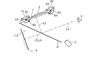
これに対し、図3(b)に示すように、像Vが第1、第2のメータ装置のダイアル表示位置より手前に見えるように表示するには、第1アクチュエータ41と第2アクチュエータ42により、第1アーム付きリンク43および第2アーム付きリンク44を第1軸線R1、第2軸線R2周りに同時回転駆動して、第3軸線R3と第4軸線R4が両方とも最下位置にくるようにする。
On the other hand, as shown in FIG. 3B, the
これにより、表示器3も最下位置に平行する結果、第2線L2に沿う方向の表示器3の表示面とハーフ・ミラー6との距離が最小まで小さくなる。したがって、像Vは、この最小距離に等しい距離分、ハーフ・ミラー6の入射位置から車両前方、すなわち第1、第2のメータ装置のダイアル表示面より手前側に離れた位置に見えるようになる。
As a result, the
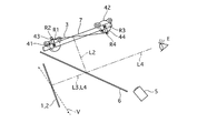
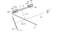
また、図4に示すように、ドライバにとって、像Vをこの上方部分が第1、第2メータ装置1、2のダイアル表示面より奥側に、またその後方部分が第1、第2メータ装置1、2のダイアル表示面より手前側に傾斜したように見えるようにするには、第1アクチュエータ41と第2アクチュエータ42により、第1アーム付きリンク43および第2アーム付きリンク44を第1軸線R1、第2軸線R2周りに回転駆動して、第3軸線R3が最上位置に、また第4軸線R4が最下位置にくるようにして表示器3を傾斜させる。
Also, as shown in FIG. 4, for the driver, the image V of the upper portion is located behind the dial display surface of the first and
これにより、第2線L2に沿う方向の表示器3の上方部分とハーフ・ミラー6との距離は、上方部分が上側になるほど大きくなるので、この距離に応じて前後移動する像Vはこの上方部分が上側になるほど第1、第2メータ装置1、2のダイアル表示面より奥側になる。一方、第2線L2に沿う方向の表示器3の下方部分とハーフ・ミラー6との距離は、下方部分が下側になるほど小さくなるので、この距離に応じて前後移動する像Vはこの下方部分が下側になるほど第1、第2メータ装置1、2のダイアル表示面より手前側になる。すなわち、像Vは、第1、第2メータ装置1、2のダイアル表示面に対し、上方側ほど奥側に、また下方側ほど手前側に傾斜した形に見えるようになる。
As a result, the distance between the upper part of the
なお、図4の場合とは、逆に第3軸線R3が最下位置に、また第4軸線R4が最上位置にくるようにして表示器3を傾斜させると、像Vは、第1、第2メータ装置1、2のダイアル表示面に対し、上方側ほど手前側に、また下方側ほど奥側に傾斜した形に見えるようになる。
In contrast to the case of FIG. 4, when the
また、図5に示すように、像Vをこの中央部分が第1、第2メータ装置1、2のダイアル表示面より手前側に来、かつその上下両側部分がダイアル表示面より奥側に来るようにして中央部分が膨らむことでこの部分が強調されたように見せるには、第1アクチュエータ41と第2アクチュエータ42により、第1アーム付きリンク43および第2アーム付きリンク44を第1軸線R1、第2軸線R2周りに回転駆動して、第3軸線R3が第1軸線R1より手前側上方位置に、また第4軸線R4が第2軸線R2の奥側上方位置に来るようにする。
Further, as shown in FIG. 5, the center portion of the image V comes closer to the front side than the dial display surfaces of the first and
これにより、第3軸線R3と第4軸線R4間の距離が狭くなり、表示器3は下に凸の半弧状の曲線形状となる。すると、第2線L2に沿う方向の表示器3の中央部分とハーフ・ミラー6間の距離が短くなるのに対し、同方向の表示器3の上下両側部分とハーフ・ミラー6間の距離は長くなる。したがって、像Vは、ドライバにとって、中央部分が第1、第2メータ装置1、2のダイアル表示面より手前側に、かつその上下両側部分がダイアル表示面より奥側に見えこととなり、中央部分が強調されて見えることになる。
As a result, the distance between the third axis R3 and the fourth axis R4 is reduced, and the
また、図6に示すように、像Vをこの中央部分が第1、第2メータ装置1、2のダイアル表示面より奥側に来、その上下両側部分がダイアル表示面より手前側に来るようにして中央側部分を大きく見せるには、第1アクチュエータ41と第2アクチュエータ42により、第1アーム付きリンク43および第2アーム付きリンク44を第1軸線R1、第2軸線R2周りに回転駆動して、第3軸線R3が第1軸線R1より手前側下方位置に、また第4軸線R4が第2軸線R2の奥側下方位置にくるようにする。
In addition, as shown in FIG. 6, the center portion of the image V comes to the back side from the dial display surfaces of the first and
これにより、第3軸線R3と第4軸線R4間の距離が狭くなり、表示器3は上に凸の半弧状の曲線となる。すると、第2線L2に沿う方向の表示器3の中央部分とハーフ・ミラー6間の距離が大きくなるのに対し、同線に沿う表示器3の上下両側部分とハーフ・ミラー6間の距離は短くなる。したがって、像Vは、ドライバにとって、上下両側部分が第1、第2メータ装置1、2のダイアル表示面より手前側に、かつその中央部分がダイアル表示面より奥側に見えることとなる。そして、中央部分の表示が大きく、また上下両側部分の表示が小さく見えるようにできる。
As a result, the distance between the third axis R3 and the fourth axis R4 is reduced, and the
以上、説明してきたように、実施例1の表示装置にあっては、以下の効果を有する。
実施例1の表示装置にあっては、表示器3を表示器変位機構4によりハーフ・ミラー6に対する距離を変えることで、第1、第2メータ装置1、2のダイアル表示に対し像Vがその手前、奥側へ移動させた位置で、ダイアル表示の実像と一部が重なるように表示することが可能となる。
この場合、表示器変位機構4により表示器3の傾斜を変えることで、像Vの上下部分が奥側と手前側との反対方向となるように傾斜した像Vを得ることが可能となる。
As described above, the display device according to the first embodiment has the following effects.
In the display device of the first embodiment, the image V is displayed on the dial display of the first and
In this case, by changing the inclination of the
また、表示器3を表示器変位機構4により上に凸、あるいは下に凸の弧状の曲面とすることで、ダイアル表示に対し像の中央部分とその上下両側部分との奥行きを異ならせて表示することが可能となる。
これにより、実施例1の表示装置では、狭い範囲にもかかわらず、より多くの情報を素早く見ることが可能となる。またこの表示にあっては、奥行き感がより自然に出せ、かつ表示内容に合わせて違和感がなく表示内容の理解が容易となる表示の種類をより増加させることが可能となる。
In addition, by displaying the
As a result, in the display device according to the first embodiment, more information can be quickly viewed regardless of a narrow range. In addition, in this display, it is possible to increase the number of display types that can give a sense of depth more naturally and that do not have a sense of incongruity according to the display content and that facilitates understanding of the display content.
このように実施例1の表示装置にあっては、比較的簡でコンパクトな構成の表示器変位機構4を用いて簡単な制御にて表示器3位置、姿勢、形状を変化させ、表示内容の理解が容易となる表示の種類を多く得ることが可能となる。
As described above, in the display device according to the first embodiment, the position, posture, and shape of the
次に、本発明に係る実施例2の表示装置について、添付の図に基づいて説明する。
実施例2の表示装置は、図7に示すように、実施例1のプロジェクタ5を無くすとともに、表示器3を実施例1のスクリーンに代えてフレキシブルな有機エレクトロルミネッセンス(EL)を用いる。この有機ELは、図示しない制御器および有機EL駆動回路に接続されて、これらから出力された表示信号により車両情報等の表示を下面側に設けた表示面に直に表示する。その他の構成は、実施例1と同じである。
Next, a display device according to a second embodiment of the present invention will be described with reference to the accompanying drawings.
As shown in FIG. 7, the display device of the second embodiment eliminates the
実施例2の表示例にあっても、表示器3の位置、姿勢・形状が実施例1と同様に、表示器変位機構4により変化させられて、ハーフ・ミラー6との距離を変えられることで、実施例1と同様な種々の像Vの位置、表示形状を変化させることが可能となる。
したがって、実施例2の表示装置にあっても、実施例1の同じ効果を得ることができる。また、実施例1のようにプロジェクタ5の設置場所を考慮する必要がなくなり、表示装置の小スペース化することができる。
Even in the display example of the second embodiment, the position, posture and shape of the
Therefore, even in the display device according to the second embodiment, the same effect as the first embodiment can be obtained. In addition, it is not necessary to consider the installation location of the
次に、上記実施例1、2の表示装置にて表示される像Vと第1、第2メータ装置1、2のダイアル表示の実像がドライバにどのように見えるかを示す具体的な表示例について以下に説明する。
Next, a specific display example showing how the image V displayed on the display devices of the first and second embodiments and the real images of the dial displays of the first and
なお、以下の表示例にあっては、ドライバには、第1、第2メータ装置1、2(文字盤上の表記は図では省略してある)の実像と表示装置による虚像表示による像Vとが一部重なって見えることがある。
像Vはこの表示範囲を示す外枠が図中太線で描いてあるが、この太線部は実際に表示されるものではなく像Vの大きさおよび奥行きの前後関係が分かるようにするためのものであって、実際にはその中の表示部分のみが表示される。また、第1、第2メータ装置1、2と像Vの外枠とが重なる部分、すなわち図中、第1、第2メータ装置1、2の丸いメータ枠内に入っている像Vの外枠の部分は、太線で描いてある部分が第1、第2メータ装置1、2のダイアル表示面の手前側に、細線で描いてある部分が第1、第2メータ装置1、2のダイアル表示面の奥側にあることを示している。
In the following display examples, the driver includes a real image of the first and
Image V has an outer frame that shows this display range drawn in bold in the figure, but this thick line is not actually displayed, but to help you understand the relationship between the size and depth of image V Actually, only the display portion is displayed. Further, the portion where the first and
まず、図8は、表示装置の表示器3を図4の位置にして像V1〜V3を車両前後方向に傾斜させ、像V1〜V3の上側部分が上側になるほど上記ダイアル表示面より奥側でかつ小さくなり、またその下側部分が下側になるほどダイアル表示面より手前側でかつ大きく表示されるようにした表示例である。
First, FIG. 8 shows that the
同図(a)は、ナビゲーションの表示例で、ナビゲーション・システムから得た情報に基づき、下に自車(自車の後部の意匠で表示)を、上(走行前方を示す)に左折指示マーク(目立つ色の矢印で示される)を、それら間に「200m先」といった案内情報(この場合は文字情報)を、それぞれ表示した例である。
同図(b)は、周辺状況監視システムから得た情報に基づき、自車後方から車両やバイク等が接近していることをドライバへ注意を促すための表示であって、上に自車を、下(自車後方を意味する)に矢印(目立つ色の警告表示)を、それぞれ表示した例である。ここでは、矢印の方向、すなわち同図の例では自車の左後から接近する車両等があることを警告する。
なお、この場合、矢印または像V全体を点滅表示させたり異なる色(赤色など)で表示させたりして、警告表示を強調してドライバに注意を喚起するようにしてもよい。
図(c)は、オート・クルーズ装置から得た情報に基づき、下に自車を、上(前方を意味する)に先行車(自車より小さい車両後部の意匠で表示)を、それぞれ表示した例である。
Figure (a) is an example of navigation display. Based on information obtained from the navigation system, the vehicle (displayed with the design at the rear of the vehicle) is displayed below, and the left turn instruction mark is displayed above (showing the front of the vehicle). In this example, guidance information (in this case, character information) such as “200 m ahead” is displayed between them (indicated by prominent colored arrows).
Figure (b) is a display to alert the driver that a vehicle or motorcycle is approaching from the back of the vehicle based on the information obtained from the surrounding situation monitoring system. In this example, an arrow (a warning display with a conspicuous color) is displayed below (meaning the rear of the vehicle). Here, a warning is given that there is a vehicle or the like approaching from the direction of the arrow, that is, in the example of FIG.
In this case, the arrow or the entire image V may be flashed or displayed in a different color (red, etc.) to emphasize the warning display and alert the driver.
Figure (c) displays the vehicle below and the preceding vehicle (indicated by the design at the rear of the vehicle smaller than the vehicle) on the top (meaning forward) based on the information obtained from the auto cruise device. It is an example.
図9は、表示装置の表示器3を図4の場合とは逆方向に傾斜させた場合の例で、自車を周りの天気、外気温などの自車周りの状況、ドライバの肩越しに見える情報などといった周辺情報を表示するものである。この場合、像V4〜V6の上側部分は、上側になるほどダイアル表示面より手前側で、かつ大きくなり、また下側部分は、下側になるほどダイアル表示面より奥側で、かつ小さく表示される。
FIG. 9 shows an example in which the
同図(a)は、下に自車を、上に「くもり」「6℃」という天気・気温の文字情報および曇りの意匠を、それぞれ表示した例である。
同図(b)は、上に自車を、下にバック・ミラーに映っている人の意匠を、それら間に「後方接近」の注意を与える文字情報を、それぞれ表示した例である。この場合も警告表示としてドライバに注意を喚起する上記表示方法を用いてもよい。
同図(c)は、下に自車を、上に室内モニタで映した後部座席の様子の画像と、それら間の「室内モニタ」の文字情報を、それぞれ表示した例である。
FIG. 4A shows an example in which the vehicle is displayed on the bottom, text information on the weather and temperature “cloudy” and “6 ° C.”, and a cloudy design are displayed on the top.
FIG. 2B is an example in which the vehicle is displayed on the top, the design of the person reflected in the rearview mirror on the bottom, and character information that gives a “rear approach” notice between them. In this case as well, the above display method for alerting the driver as a warning display may be used.
(C) in the figure is an example in which an image of the state of the rear seat displayed on the lower side of the vehicle and the indoor monitor on the upper side and the character information of “indoor monitor” therebetween are displayed.
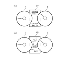
図10は、表示装置の表示器3を図3(a)の状態位置にした場合で、像V7、V8がダイアル表示面より奥まった位置に平行移動した状態で、車両の状態等が表示示される。
FIG. 10 shows the state of the vehicle and the like when the
同図(a)は、車両の状態表示であって、上に「航続距離X00Km」の文字情報を、この下に「OD・TRIP 計XXKm」(積算走行距離)の文字情報を、それぞれ表示した例である。なお、Xは任意の数を示す。
同図(b)は、空調装置の現在の作動状況表示であって、上に空気吹き出し口の状態を示すマークを、真中にファンが作動中であることを示すファンのマークを、下に「TEMP 24℃」の文字情報を、それぞれ表示した例である。なお、空調装置に関する情報に代えてたとえばオーディオ装置に関する情報など車載機器に関する情報を表示するようにしても良い。
Figure (a) shows the vehicle status display, with text information for “cruising distance X00Km” displayed on the top and text information for “OD / TRIP total XXKm” (cumulative travel distance) displayed below. It is an example. X represents an arbitrary number.
Fig. 2 (b) is a display of the current operating status of the air conditioner, with a mark indicating the state of the air outlet on the top, a fan mark indicating that the fan is operating in the middle, and This is an example of displaying character information of “TEMP 24 ° C.” respectively. In addition, it may replace with the information regarding an air conditioner, and you may make it display the information regarding vehicle equipment, such as the information regarding an audio apparatus, for example.
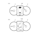
図11は、表示装置の表示器3を図3(b)の状態位置にした場合で、像V9、V10がダイアル表示面より手前の位置に平行移動した状態で、車両の状態等が表示示される。
FIG. 11 shows the state of the vehicle when the
同図(a)は、上に「eco」の文字情報を、下に「燃費 17.5Km/l」といった瞬間燃費に関する文字情報を、それぞれ表示した例である。
同図(b)は、空調装置の現在の操作状況表示であって、上に空気吹き出し口の状態を示すマークを、真中にファンが作動中であることを示すファンのマークを、下に「TEMP 24℃」の文字情報を、それぞれ表示した例である。この表示は、現在行っている操作情報に関するものなので、操作が所定時間行われなくなったら、表示が奥に引っ込んで消えるようにしてある。
FIG. 5A shows an example in which the character information “eco” is displayed on the upper side and the character information on the instantaneous fuel consumption such as “fuel consumption 17.5 Km / l” is displayed on the lower side.
Fig. 2 (b) is a display of the current operation status of the air conditioner, with a mark indicating the state of the air outlet above, a fan mark indicating that the fan is operating in the middle, and This is an example of displaying character information of “TEMP 24 ° C.” respectively. Since this display relates to the operation information currently being performed, when the operation is not performed for a predetermined time, the display is retracted deeply and disappears.
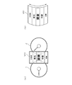
図12は、表示装置の表示器3を図5の位置にして表示器3が下に凸となる曲面に湾曲させた場合で、ナビゲーション・システムでマップの地域選択メニューを表示するようにした例である。
FIG. 12 shows an example in which the map area selection menu is displayed by the navigation system when the
同図(a)は、選択可能な各地域のうちの一部であって、像V11の上下方向中央部分(図では「関東」の文字情報)が一番大きく、しかも最も手前に見えるように、また上下方向へ離れるにしたがって表示が小さく、かつ奥側に見えるように表示される。
すなわち、この像V11は斜めからみると、図(b)のような円弧曲面上に表示されたように見える。なお、矢印で示すようにこの像V11を回転させることで、ドライバは上下方向にスクロールされる像を見ることができる。
Figure (a) is a part of each selectable area, so that the central part of the image V11 in the vertical direction (in the figure, the text information for "Kanto") is the largest and so that it can be seen at the front. In addition, the display becomes smaller as it moves away in the vertical direction and is displayed so that it can be seen on the back side.
That is, this image V11 appears to be displayed on an arcuate curved surface as shown in FIG. By rotating this image V11 as indicated by the arrow, the driver can see the image scrolled in the vertical direction.
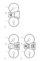
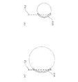
図12での表示方法は、メニュー項目が比較的多いものに向いており、選択項目数が比較的多いときは、図13(a)に示すように、側面からみて大きな円筒体の表面のダイアル面より手前側の部分上に像V12を表示するようにし、選択項目数が比較的少ないときは、同図(b)に示すように、小さな円筒体の表面のダイアル面より手前側の部分上に像V13を表示するようにする The display method in FIG. 12 is suitable for a menu having a relatively large number of menu items. When the number of selection items is relatively large, as shown in FIG. 13 (a), a dial on the surface of a large cylindrical body as viewed from the side. When the image V12 is displayed on the front side of the surface and the number of selected items is relatively small, as shown in Fig. 5 (b), the surface on the front side of the dial surface of the small cylindrical body To display the image V13
図14、15は、表示装置の表示器3を図6の位置にして表示器3が上に凸となる曲面に湾曲させたした場合で、ナビゲーション・システムでマップの地域選択メニューのうち使用頻度が低い項目を表示するようにした像V14〜V16の例である。
FIGS. 14 and 15 show the case where the
図14(a)は、選択頻度の少ない選択可能な各地域のうちの一部であって、像V14の上下方向中央部分(図では「関東」の文字情報)が一番大きく、しかも最も奥に見えるように、また上下方向へ離れるにしたがって表示が小さく、かつ手前に見えるように表示される。すなわち、円筒体の内周面側に表示されるようなイメージであり、これも表示を上下にスクロール可能である。
同図(b)は、ナビゲーションにおいて、走行履歴など、現在、過去の状態を示す情報を上下両側部分に示すもので、上には「10:13 ○○通過」との現在の時刻と現在通過の情報を、下には「走行開始より□□Km」と今回の走行距離を、その中間には自車の後部のイメージ図を、それぞれ表示した例である。ここで、上下の文字情報は比較的小さく表示される。なお、この場合、表示の奥側が自車の進行方向を表し、手前側は過去の情報を表示するようにされている。
FIG. 14 (a) is a part of each selectable area with a low selection frequency, and the center portion in the vertical direction of the image V14 (character information of “Kanto” in the figure) is the largest and the deepest. The display becomes smaller as it moves away in the vertical direction, and is displayed so that it can be seen in the foreground. That is, it is an image displayed on the inner peripheral surface side of the cylindrical body, and this can also be scrolled up and down.
Fig. (B) shows information on the current state of the past, such as the driving history, in the upper and lower parts of the navigation. The current time and the current pass of "10:13 XX Pass" are shown above. In the example below, “□□ Km from start of travel” and the current travel distance are displayed below, and an image of the rear of the vehicle is displayed in the middle. Here, the upper and lower character information is displayed relatively small. In this case, the far side of the display indicates the traveling direction of the own vehicle, and the near side displays past information.
一方、図15は、車両前方を撮像するカメラの映像を第1、第2メータ装置1、2の間に表示させるものであるが、狭い像でできるだけ広い範囲を自然にみせるため、図14の場合と同様に、表示装置の表示器3を図6の位置にして表示器3が上に凸となる曲面に湾曲させる。この状態を示したのが図15(a)である。像V16には自車前方の視界映像とともに、ナビゲーション・システムから得た情報であるすぐ先に信号機のマークと、その交差点の地名、また右折の矢印など案内マークが同時に表示される。同図(b)はその像V16である。
On the other hand, FIG. 15 displays the image of the camera that captures the front of the vehicle between the first and
この像V16の表示にあっては、表示面の凹部、すなわちその中央部分に地平線が来るように表示する。表示面を傾斜させた場合には地平線より上の表現が難しくなるが、このように凹面表示とすることで、ドライバは下側が道路の走行面で手前から前方へ延びて地平線がある中央が最も遠く、それより上側が高層ビルや空で覆われているように表示される。言い換えると、この場合の像V16にあっては、中央部分が遠くに、またその上下両側部分では近くに見えるようになる。これにより、像V16が自然な感じで表示されるので、周囲の状況を感覚的に視認しやすくなる。
また、表示の大きさは実視界に対し、非常に小さいものの、表示を凹ませることにより、より広い視野範囲のものを、位置関係をよりわかりやすく表示することが可能となる。
In the display of the image V16, the display surface is displayed such that the horizon line comes to the concave portion of the display surface, that is, the central portion thereof. When the display surface is tilted, it is difficult to express above the horizon, but by using the concave display in this way, the driver is most likely in the center where the horizon is extended from the front to the front on the road surface. It is displayed as if it is far away and the upper side is covered with skyscrapers and the sky. In other words, in the case of the image V16 in this case, the central portion can be seen far away, and the upper and lower side portions can be seen closer. As a result, the image V16 is displayed with a natural feeling, and it becomes easy to visually recognize the surrounding situation.
In addition, although the display size is very small compared to the actual field of view, it is possible to display the positional relationship in a wider visual field range in an easy-to-understand manner by denting the display.
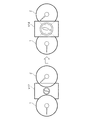
図16は、緊急の対応が必要な時などに、ドライバに注意を喚起するための表示の一つを示す図である。
同図左側に示すように、像V17を当初ダイアル表示位置より奥に表示し、かつ注意マークを小さく表示していたものを、同図右側に示すように、像V18をダイアル表示位置の手前に移動させ、かつ注意マークを拡大して強調表示するようにする。また、これら間を繰り返し表示したり、あるいは点滅表示させたりするようにしても良い。
FIG. 16 is a diagram showing one display for calling attention to the driver when an emergency response is required.
As shown on the left side of the figure, the image V17 was initially displayed behind the dial display position and the caution mark was displayed small.As shown on the right side of the figure, the image V18 was placed in front of the dial display position. Move and zoom in and highlight the caution mark. Further, the interval between them may be repeatedly displayed or blinked.
図17は、表示装置の起動時、終了時における表示を示す。起動時には、同図右側の像V19に示すように、ダイアル表示面より奥にたとえば「Welcome」の文字情報を小さく表示を行い、次第に同図右側に示す像V20のように、手前側に近づいて来、最終的にダイアル表示面の手前に上記以文字情報を移動とともに次第に拡大していくように表示するようにする。
終了時には、上記起動時とは逆に像をダイアル表示面の手前から奥へと移動させ、この移動とともに上記以文字情報が次第に小さくなってように表示するようにし、最後に表示が消えるようにする。
FIG. 17 shows a display at the time of starting and ending the display device. At the time of startup, as shown in the image V19 on the right side of the figure, the character information such as “Welcome” is displayed small behind the dial display surface, and gradually approaches the near side as shown in the image V20 on the right side of the figure. Finally, the above-mentioned character information is finally displayed in front of the dial display surface so as to gradually expand as it moves.
At the end, the image is moved from the front of the dial display surface to the back, contrary to the time of startup, so that the character information gradually becomes smaller along with this movement, and the display disappears at the end. To do.
以上、本発明を上記各実施例に基づき説明してきたが、本発明はこれらの実施例に限られず、本発明の要旨を逸脱しない範囲で設計変更等があった場合でも、本発明に含まれる。 The present invention has been described based on the above embodiments. However, the present invention is not limited to these embodiments, and is included in the present invention even when there is a design change or the like without departing from the gist of the present invention. .
たとえば、表示器3は、上記実施例のものに限られず、他の種類のものであっても良い。また、第1メータ装置1、第2メータ装置2の代わりに他の実像をドライバに見せるものであっても良い。
For example, the
表示内容、またこれに合わせた像の表示形態は上記実施例のものに限られず、その他種々の内容、組み合わせが可能である。 The display contents and the display form of the image corresponding to the display contents are not limited to those of the above-described embodiments, and various other contents and combinations are possible.
本発明の情報表示装置は、自動車用の表示装置に限られず、その他の車両用表示装置、車両以外の表示装置に適用することが可能である。 The information display device of the present invention is not limited to a display device for an automobile, and can be applied to other vehicle display devices and display devices other than vehicles.
1 第1メータ装置(第1表示装置)
2 第2メータ装置(第1表示装置)
3 表示器(第2表示装置)
4 表示器変位機構
5 プロジェクタ
6 ハーフ・ミラー
7 フレーム
41 第1アクチュエータ
41a 第1軸
42 第2アクチュエータ
42a 第2軸
43 第1アーム付きリンク
44 第2アーム付きリンク
L1 第1線
L2 第2線
L3 第3線
L4 第4線
R1 第1軸線
R2 第2軸線
R3 第3軸線
R4 第4軸線
V、V1〜V20 像
1 First meter device (first display device)
2 Second meter device (first display device)
3 Display (second display device)
4 Display displacement mechanism
5 Projector
6 Half mirror
7 frames
41 First actuator
42 Second actuator
43 Link with first arm
44 Link with second arm
L2 2nd line
L3 3rd line
L4 4th line
R1 first axis
R2 2nd axis
R3 3rd axis
R4 4th axis
V, V1 ~ V20 images
Claims (5)
該第1表示装置の実像とは異なる表示内容を表示可能な第2表示器と、
前記第1表示装置と前記第2表示器との間に配置されて、前記第1表示装置の実像を透過し、かつ前記第2表示器に表示された表示内容を反射してこの反射方向とは逆方向の位置に像を形成し、前記実像と前記像をユーザーに見せるハーフ・ミラーと、
前記第2表示器の奥側端部分および手前側端部分のそれぞれの位置を前記ハーフ・ミラーに対し独立して変位させることが可能な表示器変位機構と、
を備えたことを特徴とする表示装置。 A first display device that allows a user to visually recognize a real image;
A second display capable of displaying different display content from the real image of the first display device;
It is disposed between the first display device and the second display device, transmits the real image of the first display device, reflects the display content displayed on the second display device, and reflects the reflection direction. Forms an image in a reverse position, and the real image and a half mirror to show the image to the user;
A display displacement mechanism capable of independently displacing the positions of the rear end portion and the front end portion of the second display with respect to the half mirror;
A display device comprising:
前記表示器変位機構は、
前記第2表示器の奥側端部分に取り付けられた第1アーム付きリンクと、
前記第2表示器の手前側端部分に取り付けられた第2アーム付きリンクと、
前記第1アーム付きリンクを回転駆動可能な第1アクチュエータと、
前記第2アーム付きリンクを回転駆動可能な第2アクチュエータと、
を有することを特徴とする表示装置。 The display device according to claim 1,
The indicator displacement mechanism is
A link with a first arm attached to the back end portion of the second indicator;
A link with a second arm attached to the front side end portion of the second indicator;
A first actuator capable of rotationally driving the link with the first arm;
A second actuator capable of rotationally driving the link with the second arm;
A display device comprising:
前記表示器変位機構は、前記像を前記第1表示装置による実像の手前、奥側へ変位可能である、
ことを特徴とする表示装置。 The display device according to claim 1 or 2,
The display displacement mechanism is capable of displacing the image to the front side and the back side of the real image by the first display device.
A display device characterized by that.
前記表示器変位機構は、前記像を前記第1表示装置による実像に対し手前、奥側へ傾斜可能である、
ことを特徴とする表示装置。 The display device according to any one of claims 1 to 3,
The display displacement mechanism is capable of tilting the image toward the front and back with respect to the real image by the first display device.
A display device characterized by that.
前記表示器変位機構は、前記像を手前、奥側へ凸となる曲面上に表示可能である、
ことを特徴とする表示装置。 The display device according to any one of claims 1 to 3,
The display displacement mechanism is capable of displaying the image on a curved surface that is convex toward the front and back.
A display device characterized by that.
Priority Applications (1)
| Application Number | Priority Date | Filing Date | Title |
|---|---|---|---|
| JP2011112282A JP2012242586A (en) | 2011-05-19 | 2011-05-19 | Display device |
Applications Claiming Priority (1)
| Application Number | Priority Date | Filing Date | Title |
|---|---|---|---|
| JP2011112282A JP2012242586A (en) | 2011-05-19 | 2011-05-19 | Display device |
Publications (1)
| Publication Number | Publication Date |
|---|---|
| JP2012242586A true JP2012242586A (en) | 2012-12-10 |
Family
ID=47464369
Family Applications (1)
| Application Number | Title | Priority Date | Filing Date |
|---|---|---|---|
| JP2011112282A Withdrawn JP2012242586A (en) | 2011-05-19 | 2011-05-19 | Display device |
Country Status (1)
| Country | Link |
|---|---|
| JP (1) | JP2012242586A (en) |
Cited By (12)
| Publication number | Priority date | Publication date | Assignee | Title |
|---|---|---|---|---|
| JP2014228370A (en) * | 2013-05-22 | 2014-12-08 | 株式会社デンソー | Display device for vehicle |
| JP2014240213A (en) * | 2013-06-11 | 2014-12-25 | 株式会社デンソー | Vehicular display system |
| WO2015037325A1 (en) * | 2013-09-12 | 2015-03-19 | 株式会社デンソー | Vehicle-mounted display device |
| JP2015127800A (en) * | 2013-11-27 | 2015-07-09 | 株式会社半導体エネルギー研究所 | Display device and display device frame |
| JP2016053690A (en) * | 2014-09-04 | 2016-04-14 | 矢崎総業株式会社 | Projection display device for vehicle |
| JP2016053691A (en) * | 2014-09-04 | 2016-04-14 | 矢崎総業株式会社 | In-vehicle projection display device |
| JP2016107731A (en) * | 2014-12-04 | 2016-06-20 | 日本精機株式会社 | Head-up display device |
| US9625719B2 (en) | 2014-09-04 | 2017-04-18 | Yazaki Corporation | Projection display device |
| JP2019094058A (en) * | 2019-02-05 | 2019-06-20 | 株式会社ユピテル | System and program for vehicle |
| JP2021089354A (en) * | 2019-12-03 | 2021-06-10 | 株式会社デンソー | Display unit |
| WO2021145142A1 (en) * | 2020-01-14 | 2021-07-22 | 株式会社デンソー | Display device |
| US11380288B2 (en) | 2018-06-22 | 2022-07-05 | Mitsubishi Electric Corporation | Image display device |
-
2011
- 2011-05-19 JP JP2011112282A patent/JP2012242586A/en not_active Withdrawn
Cited By (16)
| Publication number | Priority date | Publication date | Assignee | Title |
|---|---|---|---|---|
| JP2014228370A (en) * | 2013-05-22 | 2014-12-08 | 株式会社デンソー | Display device for vehicle |
| JP2014240213A (en) * | 2013-06-11 | 2014-12-25 | 株式会社デンソー | Vehicular display system |
| WO2015037325A1 (en) * | 2013-09-12 | 2015-03-19 | 株式会社デンソー | Vehicle-mounted display device |
| JP2015127800A (en) * | 2013-11-27 | 2015-07-09 | 株式会社半導体エネルギー研究所 | Display device and display device frame |
| JP2019144572A (en) * | 2013-11-27 | 2019-08-29 | 株式会社半導体エネルギー研究所 | Display device |
| US10547831B2 (en) | 2013-11-27 | 2020-01-28 | Semiconductor Energy Laboratory Co., Ltd. | Display device and display device frame |
| JP2016053690A (en) * | 2014-09-04 | 2016-04-14 | 矢崎総業株式会社 | Projection display device for vehicle |
| JP2016053691A (en) * | 2014-09-04 | 2016-04-14 | 矢崎総業株式会社 | In-vehicle projection display device |
| US9625719B2 (en) | 2014-09-04 | 2017-04-18 | Yazaki Corporation | Projection display device |
| JP2016107731A (en) * | 2014-12-04 | 2016-06-20 | 日本精機株式会社 | Head-up display device |
| US11380288B2 (en) | 2018-06-22 | 2022-07-05 | Mitsubishi Electric Corporation | Image display device |
| JP2019094058A (en) * | 2019-02-05 | 2019-06-20 | 株式会社ユピテル | System and program for vehicle |
| JP2021089354A (en) * | 2019-12-03 | 2021-06-10 | 株式会社デンソー | Display unit |
| JP7238748B2 (en) | 2019-12-03 | 2023-03-14 | 株式会社デンソー | Display device |
| WO2021145142A1 (en) * | 2020-01-14 | 2021-07-22 | 株式会社デンソー | Display device |
| JP2021110880A (en) * | 2020-01-14 | 2021-08-02 | 株式会社デンソー | Display device |
Similar Documents
| Publication | Publication Date | Title |
|---|---|---|
| JP2012242586A (en) | Display device | |
| US8868293B2 (en) | Information display system | |
| CN101160225B (en) | Method for displaying information in vehicle and combination meter for automobile | |
| JP6123761B2 (en) | Vehicle display device | |
| JP6414096B2 (en) | In-vehicle device, control method for in-vehicle device, and control program for in-vehicle device | |
| EP2464113B1 (en) | Vehicle peripheral image generation device | |
| JP5136950B2 (en) | In-vehicle device operation device | |
| US20150302259A1 (en) | Driving assistance device and image processing program | |
| CN111788459A (en) | Appearance of auxiliary information on the display unit | |
| CN101889234A (en) | Display device for a motor vehicle | |
| JP2006501443A (en) | Method and apparatus for displaying navigation information on a vehicle | |
| US20170160552A1 (en) | Vehicular Information Display Apparatus | |
| TWI728117B (en) | Dynamic information system and method for operating a dynamic information system | |
| JP2006001377A (en) | Vehicle display device | |
| JP2014189213A (en) | Vehicular display device | |
| JP2020071415A (en) | Heads up display system | |
| JP5160665B2 (en) | In-vehicle meter display device | |
| CN110831803B (en) | Method, device and computer program for operating a vehicle operating system | |
| JP4761551B2 (en) | In-vehicle meter display device | |
| JP2019056884A (en) | Superimposed image display device | |
| JP7509070B2 (en) | Virtual Image Display | |
| WO2022210172A1 (en) | Vehicular display system, vehicular display method, and vehicular display program | |
| CN114867992A (en) | Method and apparatus for presenting virtual navigation elements | |
| JP6699601B2 (en) | Vehicle display | |
| JP2006330360A (en) | Vehicle information display device |
Legal Events
| Date | Code | Title | Description |
|---|---|---|---|
| A300 | Application deemed to be withdrawn because no request for examination was validly filed |
Free format text: JAPANESE INTERMEDIATE CODE: A300 Effective date: 20140805 |