JP2012243444A - 真空インタラプタ - Google Patents
真空インタラプタ Download PDFInfo
- Publication number
- JP2012243444A JP2012243444A JP2011110163A JP2011110163A JP2012243444A JP 2012243444 A JP2012243444 A JP 2012243444A JP 2011110163 A JP2011110163 A JP 2011110163A JP 2011110163 A JP2011110163 A JP 2011110163A JP 2012243444 A JP2012243444 A JP 2012243444A
- Authority
- JP
- Japan
- Prior art keywords
- magnetic
- electrode
- magnetic body
- shaped
- shape
- Prior art date
- Legal status (The legal status is an assumption and is not a legal conclusion. Google has not performed a legal analysis and makes no representation as to the accuracy of the status listed.)
- Granted
Links
- 230000004907 flux Effects 0.000 abstract description 41
- 238000009826 distribution Methods 0.000 abstract description 14
- 238000005219 brazing Methods 0.000 description 8
- 239000000696 magnetic material Substances 0.000 description 8
- 239000000463 material Substances 0.000 description 5
- 238000000034 method Methods 0.000 description 5
- 230000000149 penetrating effect Effects 0.000 description 2
- GXDVEXJTVGRLNW-UHFFFAOYSA-N [Cr].[Cu] Chemical compound [Cr].[Cu] GXDVEXJTVGRLNW-UHFFFAOYSA-N 0.000 description 1
- 230000000903 blocking effect Effects 0.000 description 1
- 238000010586 diagram Methods 0.000 description 1
- 230000000694 effects Effects 0.000 description 1
- 230000005611 electricity Effects 0.000 description 1
Images






Landscapes
- High-Tension Arc-Extinguishing Switches Without Spraying Means (AREA)
Abstract
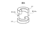
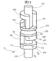
【解決手段】上記課題を解決するために、本発明の真空インタラプタは、向かい合う一対の電極の背面にそれぞれ通電軸を有し、当該各通電軸の周囲に磁性体を設けた真空インタラプタにおいて、一方の電極の背面から前記通電軸の軸方向に所定の距離を保って配置された、U字形でかつ該U字の両端部から前記通電軸の軸方向に伸びた柱状部が前記電極と当接する磁性体と、他方の電極の背面に当接した、円弧形でかつその両端部が前記U字形磁性体の柱状部の軸方向の延長線上に位置する磁性体とを1組として第一の磁気経路を形成し、さらに前記U字形および円弧形を1組とする磁性体と同一形状のもう1組の磁性体を、それぞれ対向する電極の背面に約180度ずらして配置し、第二の磁気経路を形成したことを特徴とする。
【選択図】図1
Description
2A、2B 接触子
3A、3B 円弧形磁性体
4A、4B U字形磁性体
Φ5、Φ6 閉じた磁力線(ループ)
g 電極間(ギャップ)
d 接触子の厚さ
Claims (1)
- 向かい合う一対の電極の背面にそれぞれ通電軸を有し、当該各通電軸の周囲に磁性体を設けた真空インタラプタにおいて、一方の電極の背面から前記通電軸の軸方向に所定の距離を保って配置された、U字形でかつ該U字の両端部から前記通電軸の軸方向に伸びた柱状部が前記電極と当接する磁性体と、他方の電極の背面に当接した、円弧形でかつその両端部が前記U字形磁性体の柱状部の軸方向の延長線上に位置する磁性体とを1組として第一の磁気経路を形成し、さらに前記U字形および円弧形を1組とする磁性体と同一形状のもう1組の磁性体を、それぞれ対向する電極の背面に約180度ずらして配置し、第二の磁気経路を形成したことを特徴とする真空インタラプタ。
Priority Applications (1)
| Application Number | Priority Date | Filing Date | Title |
|---|---|---|---|
| JP2011110163A JP5648577B2 (ja) | 2011-05-17 | 2011-05-17 | 真空インタラプタ |
Applications Claiming Priority (1)
| Application Number | Priority Date | Filing Date | Title |
|---|---|---|---|
| JP2011110163A JP5648577B2 (ja) | 2011-05-17 | 2011-05-17 | 真空インタラプタ |
Publications (2)
| Publication Number | Publication Date |
|---|---|
| JP2012243444A true JP2012243444A (ja) | 2012-12-10 |
| JP5648577B2 JP5648577B2 (ja) | 2015-01-07 |
Family
ID=47464971
Family Applications (1)
| Application Number | Title | Priority Date | Filing Date |
|---|---|---|---|
| JP2011110163A Active JP5648577B2 (ja) | 2011-05-17 | 2011-05-17 | 真空インタラプタ |
Country Status (1)
| Country | Link |
|---|---|
| JP (1) | JP5648577B2 (ja) |
Cited By (2)
| Publication number | Priority date | Publication date | Assignee | Title |
|---|---|---|---|---|
| WO2019180030A1 (en) * | 2018-03-21 | 2019-09-26 | Siemens Aktiengesellschaft | Vacuum arc-extinguishing chamber used for contactors and contactor |
| WO2019188699A1 (ja) * | 2018-03-29 | 2019-10-03 | 三菱電機株式会社 | 真空バルブ |
Citations (5)
| Publication number | Priority date | Publication date | Assignee | Title |
|---|---|---|---|---|
| JPS5486782A (en) * | 1977-12-05 | 1979-07-10 | Hazemeijer Bv | Vacuum switch |
| JPS60258816A (ja) * | 1984-03-19 | 1985-12-20 | ホレツク システメン アンド コンポーネンテン ベーヴエー | 軸方向磁場を作るための馬蹄形鉄磁石エレメント付き真空スイッチ |
| JPH09320413A (ja) * | 1996-06-04 | 1997-12-12 | Toshiba Corp | 真空バルブ |
| JPH11260207A (ja) * | 1998-03-12 | 1999-09-24 | Toshiba Corp | 真空バルブ |
| JPH11260208A (ja) * | 1998-03-13 | 1999-09-24 | Toshiba Corp | 真空バルブ |
-
2011
- 2011-05-17 JP JP2011110163A patent/JP5648577B2/ja active Active
Patent Citations (6)
| Publication number | Priority date | Publication date | Assignee | Title |
|---|---|---|---|---|
| JPS5486782A (en) * | 1977-12-05 | 1979-07-10 | Hazemeijer Bv | Vacuum switch |
| US4271340A (en) * | 1977-12-05 | 1981-06-02 | Hazemeijer B.V. | Electrical vacuum switch having means for generating an axial magnetic field between the contact faces |
| JPS60258816A (ja) * | 1984-03-19 | 1985-12-20 | ホレツク システメン アンド コンポーネンテン ベーヴエー | 軸方向磁場を作るための馬蹄形鉄磁石エレメント付き真空スイッチ |
| JPH09320413A (ja) * | 1996-06-04 | 1997-12-12 | Toshiba Corp | 真空バルブ |
| JPH11260207A (ja) * | 1998-03-12 | 1999-09-24 | Toshiba Corp | 真空バルブ |
| JPH11260208A (ja) * | 1998-03-13 | 1999-09-24 | Toshiba Corp | 真空バルブ |
Cited By (4)
| Publication number | Priority date | Publication date | Assignee | Title |
|---|---|---|---|---|
| WO2019180030A1 (en) * | 2018-03-21 | 2019-09-26 | Siemens Aktiengesellschaft | Vacuum arc-extinguishing chamber used for contactors and contactor |
| WO2019188699A1 (ja) * | 2018-03-29 | 2019-10-03 | 三菱電機株式会社 | 真空バルブ |
| JPWO2019188699A1 (ja) * | 2018-03-29 | 2020-04-30 | 三菱電機株式会社 | 真空バルブ |
| US11282661B2 (en) | 2018-03-29 | 2022-03-22 | Mitsubishi Electric Corporation | Vacuum interrupter |
Also Published As
| Publication number | Publication date |
|---|---|
| JP5648577B2 (ja) | 2015-01-07 |
Similar Documents
| Publication | Publication Date | Title |
|---|---|---|
| KR102606473B1 (ko) | 단락전류 방지용 직류 릴레이 | |
| KR20120079154A (ko) | 진공밸브 | |
| JP5249255B2 (ja) | 真空遮断器の電極 | |
| KR101309458B1 (ko) | 진공밸브 | |
| JP2014038939A (ja) | 磁気エンコーダの着磁装置 | |
| TW201214499A (en) | Multi-axis lens, beam system making use of the compound lens, and method of manufacturing the compound lens | |
| JP5648577B2 (ja) | 真空インタラプタ | |
| KR100252839B1 (ko) | 진공밸브 | |
| JP2010027946A (ja) | 磁気コア | |
| KR101838115B1 (ko) | 자성 부품 | |
| CN105027248B (zh) | 真空阀 | |
| JP6651878B2 (ja) | 真空バルブ | |
| JP5664333B2 (ja) | 回路遮断器 | |
| JP2001006501A (ja) | 真空バルブ | |
| JP6160071B2 (ja) | インダクタ | |
| JP2010225901A (ja) | リアクトル | |
| WO2011052109A1 (ja) | 真空バルブ | |
| JP2015012224A (ja) | 零相変流器 | |
| JP4935716B2 (ja) | トランス | |
| JP7664922B2 (ja) | 真空バルブ | |
| JP5302723B2 (ja) | 真空バルブ | |
| JP2009088084A (ja) | 静止誘導電器 | |
| JP2008135338A (ja) | 真空バルブ | |
| JP2005168110A (ja) | 回転電機 | |
| JP2006197710A (ja) | 回転電機の固定子 |
Legal Events
| Date | Code | Title | Description |
|---|---|---|---|
| A711 | Notification of change in applicant |
Free format text: JAPANESE INTERMEDIATE CODE: A712 Effective date: 20121101 |
|
| A711 | Notification of change in applicant |
Free format text: JAPANESE INTERMEDIATE CODE: A712 Effective date: 20130513 |
|
| A621 | Written request for application examination |
Free format text: JAPANESE INTERMEDIATE CODE: A621 Effective date: 20131226 |
|
| A521 | Written amendment |
Free format text: JAPANESE INTERMEDIATE CODE: A821 Effective date: 20140626 |
|
| RD02 | Notification of acceptance of power of attorney |
Free format text: JAPANESE INTERMEDIATE CODE: A7422 Effective date: 20140626 |
|
| A977 | Report on retrieval |
Free format text: JAPANESE INTERMEDIATE CODE: A971007 Effective date: 20140724 |
|
| A131 | Notification of reasons for refusal |
Free format text: JAPANESE INTERMEDIATE CODE: A131 Effective date: 20140729 |
|
| A521 | Written amendment |
Free format text: JAPANESE INTERMEDIATE CODE: A523 Effective date: 20140925 |
|
| TRDD | Decision of grant or rejection written | ||
| A01 | Written decision to grant a patent or to grant a registration (utility model) |
Free format text: JAPANESE INTERMEDIATE CODE: A01 Effective date: 20141014 |
|
| A61 | First payment of annual fees (during grant procedure) |
Free format text: JAPANESE INTERMEDIATE CODE: A61 Effective date: 20141027 |
|
| R150 | Certificate of patent or registration of utility model |
Ref document number: 5648577 Country of ref document: JP Free format text: JAPANESE INTERMEDIATE CODE: R150 |