JP2012243473A - Manufacturing method of electrode - Google Patents
Manufacturing method of electrode Download PDFInfo
- Publication number
- JP2012243473A JP2012243473A JP2011110744A JP2011110744A JP2012243473A JP 2012243473 A JP2012243473 A JP 2012243473A JP 2011110744 A JP2011110744 A JP 2011110744A JP 2011110744 A JP2011110744 A JP 2011110744A JP 2012243473 A JP2012243473 A JP 2012243473A
- Authority
- JP
- Japan
- Prior art keywords
- drying
- electrode mixture
- paste
- positive electrode
- mixture paste
- Prior art date
- Legal status (The legal status is an assumption and is not a legal conclusion. Google has not performed a legal analysis and makes no representation as to the accuracy of the status listed.)
- Pending
Links
Images





Classifications
-
- H—ELECTRICITY
- H01—ELECTRIC ELEMENTS
- H01M—PROCESSES OR MEANS, e.g. BATTERIES, FOR THE DIRECT CONVERSION OF CHEMICAL ENERGY INTO ELECTRICAL ENERGY
- H01M4/00—Electrodes
- H01M4/02—Electrodes composed of, or comprising, active material
- H01M4/04—Processes of manufacture in general
- H01M4/0402—Methods of deposition of the material
- H01M4/0404—Methods of deposition of the material by coating on electrode collectors
-
- H—ELECTRICITY
- H01—ELECTRIC ELEMENTS
- H01M—PROCESSES OR MEANS, e.g. BATTERIES, FOR THE DIRECT CONVERSION OF CHEMICAL ENERGY INTO ELECTRICAL ENERGY
- H01M4/00—Electrodes
- H01M4/02—Electrodes composed of, or comprising, active material
- H01M4/04—Processes of manufacture in general
- H01M4/0471—Processes of manufacture in general involving thermal treatment, e.g. firing, sintering, backing particulate active material, thermal decomposition, pyrolysis
-
- H—ELECTRICITY
- H01—ELECTRIC ELEMENTS
- H01M—PROCESSES OR MEANS, e.g. BATTERIES, FOR THE DIRECT CONVERSION OF CHEMICAL ENERGY INTO ELECTRICAL ENERGY
- H01M4/00—Electrodes
- H01M4/02—Electrodes composed of, or comprising, active material
- H01M4/13—Electrodes for accumulators with non-aqueous electrolyte, e.g. for lithium-accumulators; Processes of manufacture thereof
- H01M4/139—Processes of manufacture
-
- Y—GENERAL TAGGING OF NEW TECHNOLOGICAL DEVELOPMENTS; GENERAL TAGGING OF CROSS-SECTIONAL TECHNOLOGIES SPANNING OVER SEVERAL SECTIONS OF THE IPC; TECHNICAL SUBJECTS COVERED BY FORMER USPC CROSS-REFERENCE ART COLLECTIONS [XRACs] AND DIGESTS
- Y02—TECHNOLOGIES OR APPLICATIONS FOR MITIGATION OR ADAPTATION AGAINST CLIMATE CHANGE
- Y02E—REDUCTION OF GREENHOUSE GAS [GHG] EMISSIONS, RELATED TO ENERGY GENERATION, TRANSMISSION OR DISTRIBUTION
- Y02E60/00—Enabling technologies; Technologies with a potential or indirect contribution to GHG emissions mitigation
- Y02E60/10—Energy storage using batteries
Landscapes
- Engineering & Computer Science (AREA)
- Manufacturing & Machinery (AREA)
- Chemical & Material Sciences (AREA)
- Chemical Kinetics & Catalysis (AREA)
- Electrochemistry (AREA)
- General Chemical & Material Sciences (AREA)
- Battery Electrode And Active Subsutance (AREA)
Abstract
【課題】 電極合材ペーストを乾燥させて形成する電極合材層にひび割れが生じるのを抑制することができる電極の製造方法を提供する。
【解決手段】 第1面11b及び第2面11cを有する電極集電部材11の第1面11bに、電極合材ペースト12を塗工する第1塗工工程(ステップS1)と、第1面11bに塗工した電極合材ペースト12を乾燥させる第1乾燥工程(ステップS2)とを備える。第1乾燥工程(ステップS2)では、乾燥初期段階において、電極集電部材11の第1面11bに電極合材ペースト12が塗工された第1ペースト塗工部材10Bに対し、第1面11b側から加える熱量よりも第2面11c側から加える熱量を大きくして、電極合材ペースト12を乾燥させる。
【選択図】 図1PROBLEM TO BE SOLVED: To provide an electrode manufacturing method capable of suppressing the occurrence of cracks in an electrode mixture layer formed by drying an electrode mixture paste.
A first application step (step S1) of applying an electrode mixture paste 12 to a first surface 11b of an electrode current collector 11 having a first surface 11b and a second surface 11c, and a first surface A first drying step (step S2) for drying the electrode mixture paste 12 applied to 11b. In the first drying step (step S2), the first surface 11b is applied to the first paste coating member 10B in which the electrode mixture paste 12 is applied to the first surface 11b of the electrode current collecting member 11 in the initial drying stage. The amount of heat applied from the second surface 11c side is made larger than the amount of heat applied from the side, and the electrode mixture paste 12 is dried.
[Selection] Figure 1
Description
本発明は、電極の製造方法に関する。 The present invention relates to an electrode manufacturing method.
近年、電池用電極の製造方法として、様々な方法が提案されている。例えば、特許文献1には、二次電池用電極板の製造方法が開示されている。
In recent years, various methods have been proposed as methods for manufacturing battery electrodes. For example,
特許文献1には、次のような製造方法が記載されている。具体的には、まず、電極集電部材(アルミニウム箔)の表面(第1面)に、塗着液(電極合材ペースト)を塗着する。次いで、電極集電部材(アルミニウム箔)の両面側(第1面側及び第2面側)に配置されたヒータファンによって、電極集電部材の第1面に塗工した電極合材ペーストを乾燥させる。具体的には、電極集電部材の第1面に電極合材ペーストを塗工したもの(これを第1ペースト塗工部材という)に対し、第1面側に配置された第1ヒータファンから熱風を当てると共に、第2面側に配置された第2ヒータファンからも熱風を当てることによって、電極合材ペーストを乾燥させる。但し、第1ヒータファンと第2ヒータファンとにおいて、送出される熱風の温度及び風量を等しい値としている。
ところが、特許文献1のように、第1ヒータファンと第2ヒータファンとについて、送出される熱風の温度及び風量を等しい値として、電極集電部材の第1面に電極合材ペーストを塗工した第1ペースト塗工部材に対し、第1面側に配置された第1ヒータファンから熱風を当てると共に、第2面側に配置された第2ヒータファンからも熱風を当てることによって、電極合材ペーストを乾燥させると、電極合材層(電極合材ペーストが乾燥して形成される電極合材層)にひび割れが生じることがあった。
However, as in
本発明者が検討したところ、上述のようにして電極合材ペーストを乾燥させた場合、電極合材ペーストの内部(電極集電部材側)に多量の溶媒が残っている状態で、電極合材ペーストの表面が早期に乾燥する傾向にあった。このため、表面の薄い膜(電極合材ペーストの表面が乾燥して膜になったもの)に収縮応力がかかり、この収縮応力が表面の薄い膜の強度を上回ることにより、ひび割れが発生すると推測される。 As a result of investigation by the present inventors, when the electrode mixture paste is dried as described above, the electrode mixture is left in a state where a large amount of solvent remains in the electrode mixture paste (on the electrode current collecting member side). The paste surface tended to dry early. For this reason, shrinkage stress is applied to the thin film (the electrode mixture paste surface is dried to form a film), and it is assumed that cracking occurs when this shrinkage stress exceeds the strength of the thin film. Is done.
本発明は、かかる問題点に鑑みてなされたものであって、電極合材ペーストを乾燥させて形成する電極合材層にひび割れが生じるのを抑制することができる電極の製造方法を提供することを目的とする。 This invention is made in view of this problem, Comprising: It provides the manufacturing method of the electrode which can suppress that a crack arises in the electrode compound-material layer formed by drying electrode compound-material paste. With the goal.
本発明の一態様は、第1面及び第2面を有する電極集電部材の上記第1面に、電極合材ペーストを塗工する第1塗工工程と、上記第1面に塗工した上記電極合材ペーストを乾燥させる第1乾燥工程と、を備える電極の製造方法において、上記第1乾燥工程は、乾燥初期段階において、上記電極集電部材の上記第1面に上記電極合材ペーストが塗工された第1ペースト塗工部材に対し、上記第1面側から加える熱量よりも上記第2面側から加える熱量を大きくして、上記電極合材ペーストを乾燥させる電極の製造方法である。 In one aspect of the present invention, the first surface of the electrode current collector having the first surface and the second surface is coated on the first surface, and the first surface is coated on the first surface. A first drying step of drying the electrode mixture paste, wherein the first drying step is performed at an initial stage of drying, the electrode mixture paste on the first surface of the electrode current collector. In the electrode manufacturing method of drying the electrode mixture paste, the amount of heat applied from the second surface side is larger than the amount of heat applied from the first surface side to the first paste coated member coated with is there.
上述の製造方法では、第1乾燥工程の乾燥初期段階において、電極集電部材の第1面に電極合材ペーストが塗工された第1ペースト塗工部材に対し、第1面側から加える熱量よりも第2面側から加える熱量を大きくして、電極合材ペーストを乾燥させる。すなわち、第1面に塗工した電極合材ペーストの乾燥初期段階では、電極合材ペーストを塗工した第1面側よりも、電極合材ペーストを塗工していない第2面側から加える熱量を大きくして、電極合材ペーストを乾燥させる。これにより、電極合材ペーストの内部(電極集電部材側)の乾燥を早めることができ、その結果、電極合材ペーストが乾燥して形成される電極合材層にひび割れが生じるのを抑制することができる。 In the manufacturing method described above, the amount of heat applied from the first surface side to the first paste coated member in which the electrode mixture paste is coated on the first surface of the electrode current collecting member in the initial drying stage of the first drying step. The amount of heat applied from the second surface side is increased to dry the electrode mixture paste. That is, in the initial drying stage of the electrode mixture paste applied to the first surface, the electrode mixture paste is applied from the second surface side not coated with the electrode mixture paste, rather than the first surface side coated with the electrode mixture paste. The amount of heat is increased to dry the electrode mixture paste. As a result, the inside of the electrode mixture paste (on the electrode current collecting member side) can be quickly dried, and as a result, the electrode mixture layer formed by drying the electrode mixture paste is prevented from cracking. be able to.
なお、ひび割れが生じている電極合材層を有する電極を電池に用いた場合、当該電極において反応が不均一となり、電池特性が低下する虞がある。従って、電極合材ペーストを乾燥させて形成した電極合材層にひび割れが生じていることは好ましくない。
また、電極合材ペーストは、溶媒を含む電極合材であり、例えば、活物質とバインダと溶媒を混合させたものである。
In addition, when the electrode which has the electrode compound-material layer in which the crack has produced is used for a battery, reaction becomes non-uniform | heterogenous in the said electrode and there exists a possibility that a battery characteristic may fall. Therefore, it is not preferable that the electrode mixture layer formed by drying the electrode mixture paste is cracked.
Further, the electrode mixture paste is an electrode mixture containing a solvent, for example, a mixture of an active material, a binder, and a solvent.
さらに、上記の電極の製造方法であって、前記第1乾燥工程は、前記乾燥初期段階において、前記第1ペースト塗工部材に対し、前記第2面側から熱風を当てる電極の製造方法とすると良い。 Furthermore, in the electrode manufacturing method, the first drying step is an electrode manufacturing method in which hot air is applied to the first paste coating member from the second surface side in the initial drying stage. good.
乾燥初期段階において、第1ペースト塗工部材(電極集電部材の第1面に電極合材ペーストが塗工されたもの)に対し、(第1面側からは熱風を当てることなく)第2面側から熱風を当てることで、第1面側から加える熱量よりも第2面側から加える熱量を大きくして、電極合材ペーストを乾燥させることができる。これにより、電極合材層にひび割れが生じるのを抑制することができる。 In the initial stage of drying, the second paste coating member (the electrode current collector member coated with the electrode mixture paste on the first surface) is subjected to the second (without applying hot air from the first surface side). By applying hot air from the surface side, the amount of heat applied from the second surface side can be made larger than the amount of heat applied from the first surface side, and the electrode mixture paste can be dried. Thereby, it can suppress that a crack arises in an electrode compound-material layer.
あるいは、前記の電極の製造方法であって、前記第1乾燥工程は、前記乾燥初期段階において、前記第1ペースト塗工部材に対し、前記第2面側から赤外線を照射する電極の製造方法とすると良い。 Alternatively, in the method for manufacturing the electrode, in the first drying step, in the initial stage of drying, the electrode manufacturing method for irradiating the first paste coated member with infrared rays from the second surface side; Good.
乾燥初期段階において、第1ペースト塗工部材(電極集電部材の第1面に電極合材ペーストが塗工されたもの)に対し、(第1面側からは赤外線を照射することなく)第2面側から赤外線を照射することで、第1面側から加える熱量よりも第2面側から加える熱量を大きくして、電極合材ペーストを乾燥させることができる。これにより、電極合材層にひび割れが生じるのを抑制することができる。 In the initial stage of drying, the first paste coating member (the electrode current collector member coated with the electrode mixture paste on the first surface of the electrode current collecting member) is the first (without irradiating infrared rays from the first surface side) By irradiating infrared rays from the second surface side, the amount of heat applied from the second surface side can be made larger than the amount of heat applied from the first surface side, and the electrode mixture paste can be dried. Thereby, it can suppress that a crack arises in an electrode compound-material layer.
さらに、上記いずれかの電極の製造方法であって、前記第1塗工工程では、前記第1面に塗工する前記電極合材ペーストの目付量を10mg/cm2 以上とし、前記第1乾燥工程では、上記電極合材ペーストの乾燥時間を、[目付量(mg/cm2 )/乾燥時間(秒)]≧0.3を満たす時間に設定する電極の製造方法とすると良い。 Furthermore, in any one of the above electrode manufacturing methods, in the first coating step, the basis weight of the electrode mixture paste applied to the first surface is set to 10 mg / cm 2 or more, and the first drying is performed. In the process, it is preferable that the electrode mixture paste has a drying time set to a time satisfying [weight per unit area (mg / cm 2 ) / drying time (seconds)] ≧ 0.3.
電気自動車やハイブリッド自動車の駆動用電源として用いる電池では、高容量化が求められている。これに対し、上述の製造方法では、第1塗工工程において、第1面に塗工する電極合材ペーストの目付量を10mg/cm2 以上としている。電極合材ペーストの目付量を10mg/cm2 以上と大きくすることで、電池を高容量にすることができる。 A battery used as a power source for driving an electric vehicle or a hybrid vehicle is required to have a high capacity. On the other hand, in the manufacturing method described above, the basis weight of the electrode mixture paste applied to the first surface is set to 10 mg / cm 2 or more in the first coating step. By increasing the basis weight of the electrode mixture paste to 10 mg / cm 2 or more, the battery can have a high capacity.
また、上述の製造方法では、第1乾燥工程において、電極合材ペーストの乾燥時間を、[目付量(mg/cm2 )/乾燥時間(秒)]≧0.3を満たす時間に設定する。例えば、目付量を20mg/cm2 として電極集電部材に塗工した電極合材ペーストを、66.7秒以内に乾燥させる(乾燥時間を66.7秒以内とする)。このように、乾燥時
間を短くすることで、電極合材ペーストの目付量を大きくしつつも、電極の生産効率を高くすることができる。なお、電極合材ペーストの乾燥時間を、[目付量(mg/cm2 )/乾燥時間(秒)]≧0.3を満たす時間に設定して、電極合材ペーストを適切に乾燥させるためには、乾燥温度を高くする(例えば、150℃以上にする)必要がある。
In the manufacturing method described above, in the first drying step, the drying time of the electrode mixture paste is set to a time satisfying [weight per unit area (mg / cm 2 ) / drying time (seconds)] ≧ 0.3. For example, the electrode mixture paste applied to the electrode current collector with a basis weight of 20 mg / cm 2 is dried within 66.7 seconds (the drying time is within 66.7 seconds). Thus, by shortening the drying time, it is possible to increase the electrode production efficiency while increasing the basis weight of the electrode mixture paste. In order to appropriately dry the electrode mixture paste by setting the drying time of the electrode mixture paste to a time satisfying [weight per unit area (mg / cm 2 ) / drying time (seconds)] ≧ 0.3 Requires a high drying temperature (for example, 150 ° C. or higher).
ところで、電極合材ペーストの目付量を10mg/cm2 以上と大きくした場合において、特許文献1のように、第1ヒータファンと第2ヒータファンとについて、送出される熱風の温度及び風量を等しい値として、第1ペースト塗工部材(電極集電部材の第1面に電極合材ペーストを塗工したもの)に対し、第1面側に配置された第1ヒータファンから熱風を当てると共に、第2面側に配置された第2ヒータファンからも熱風を当てることによって、電極合材ペーストを乾燥させた場合には、特にひび割れが生じ易かった。その上、高温で短時間で乾燥させた場合、具体的には、例えば、電極合材ペーストの乾燥時間を、[目付量(mg/cm2 )/乾燥時間(秒)]≧0.3を満たす時間に設定し、乾燥温度を150℃程度に設定して、電極合材ペーストを乾燥させた場合には、更にひび割れが生じやすくなる傾向にあった。
By the way, when the basis weight of the electrode mixture paste is increased to 10 mg / cm 2 or more, as in
これに対し、上述の製造方法では、前述のように、第1乾燥工程の乾燥初期段階において、第1ペースト塗工部材に対し、第1面側から加える熱量よりも第2面側から加える熱量を大きくして、電極合材ペーストを乾燥させる。これにより、上述のような目付量及び乾燥時間に設定しても、電極合材層にひび割れが生じるのを抑制することができる。 On the other hand, in the above-described manufacturing method, as described above, in the initial drying stage of the first drying process, the amount of heat applied to the first paste coating member from the second surface side rather than the amount of heat applied from the first surface side. Is increased to dry the electrode mixture paste. Thereby, even if it sets to the above areal weights and drying time, it can suppress that a crack arises in an electrode compound-material layer.
さらに、上記いずれかの電極の製造方法であって、前記第1乾燥工程の後、前記電極集電部材の前記第2面に電極合材ペーストを塗工する第2塗工工程と、上記第2面に塗工した上記電極合材ペーストを乾燥させる第2乾燥工程と、を備え、上記第2乾燥工程は、乾燥初期段階において、上記電極集電部材の上記第2面に上記電極合材ペーストが塗工された第2ペースト塗工部材に対し、上記第2面側から加える熱量よりも前記第1面側から加える熱量を大きくして、上記電極合材ペーストを乾燥させる電極の製造方法とすると良い。 Furthermore, in any one of the above-described electrode manufacturing methods, after the first drying step, a second coating step of applying an electrode mixture paste to the second surface of the electrode current collector, and the first A second drying step of drying the electrode mixture paste coated on two surfaces, wherein the second drying step is performed on the second surface of the electrode current collecting member in the initial stage of drying. A method of manufacturing an electrode for drying the electrode mixture paste by increasing the amount of heat applied from the first surface side to the second paste coated member to which the paste is applied from the second surface side. And good.
上述の製造方法では、電極集電部材の第1面のみならず、第2面にも、電極合材ペーストを塗工して乾燥させる。具体的には、第1乾燥工程後の第2塗工工程において、電極集電部材の第2面に電極合材ペーストを塗工する。その後、第2乾燥工程において、第2面に塗工した電極合材ペーストを乾燥させる。 In the manufacturing method described above, the electrode mixture paste is applied to the second surface as well as the first surface of the electrode current collector and dried. Specifically, in the second coating step after the first drying step, the electrode mixture paste is applied to the second surface of the electrode current collector. Thereafter, in the second drying step, the electrode mixture paste applied to the second surface is dried.
しかも、上述の製造方法では、第2乾燥工程の乾燥初期段階において、第2ペースト塗工部材(電極集電部材の第2面に電極合材ペーストが塗工されたもの)に対し、第2面側から加える熱量よりも第1面側から加える熱量を大きくして、電極合材ペーストを乾燥させる。すなわち、第2面に塗工した電極合材ペーストの乾燥初期段階では、電極合材ペーストを塗工した第2面側よりも、既に電極合材ペーストを乾燥させて電極合材層とした第1面側から加える熱量を大きくして、電極合材ペーストを乾燥させる。これにより、第2面に塗工した電極合材ペーストの内部(電極集電部材側)の乾燥を早めることができ、その結果、電極合材層にひび割れが生じるのを抑制することができる。従って、上述の製造方法では、第1面及び第2面に塗工した両電極合材ペーストを乾燥させて形成される電極合材層について、ひび割れを抑制することができる。 Moreover, in the manufacturing method described above, the second paste application member (the electrode mixture paste applied to the second surface of the electrode current collector) is second in the initial drying stage of the second drying step. The amount of heat applied from the first surface side is made larger than the amount of heat applied from the surface side, and the electrode mixture paste is dried. That is, at the initial drying stage of the electrode mixture paste applied to the second surface, the electrode mixture paste is already dried to form an electrode mixture layer rather than the second surface side coated with the electrode mixture paste. The amount of heat applied from the one side is increased to dry the electrode mixture paste. Thereby, the inside (electrode current collection member side) of the electrode compound paste applied to the second surface can be accelerated, and as a result, the generation of cracks in the electrode compound layer can be suppressed. Therefore, in the above-described manufacturing method, cracks can be suppressed in the electrode mixture layer formed by drying both electrode mixture pastes applied to the first surface and the second surface.
さらに、上記の電極の製造方法であって、前記第2乾燥工程は、前記乾燥初期段階において、前記第2ペースト塗工部材に対し、前記第1面側から熱風を当てる電極の製造方法とすると良い。 Further, in the electrode manufacturing method, the second drying step is an electrode manufacturing method in which hot air is applied to the second paste coating member from the first surface side in the initial drying stage. good.
乾燥初期段階において、第2ペースト塗工部材(電極集電部材の第2面に電極合材ペーストが塗工されたもの)に対し、(第2面側からは熱風を当てることなく)第1面側から熱風を当てることで、第2面側から加える熱量よりも第1面側から加える熱量を大きくして、電極合材ペーストを乾燥させることができる。これにより、第2面に塗工した電極合材ペーストを乾燥させて形成される電極合材層についても、ひび割れを抑制することができる。 In the initial stage of drying, the first paste coating member (the electrode current collector member coated with the electrode mixture paste) is the first (without applying hot air from the second surface side). By applying hot air from the surface side, the amount of heat applied from the first surface side can be made larger than the amount of heat applied from the second surface side, and the electrode mixture paste can be dried. Thereby, a crack can be suppressed also about the electrode compound-material layer formed by drying the electrode compound paste applied to the 2nd surface.
あるいは、前記の電極の製造方法であって、前記第2乾燥工程は、前記乾燥初期段階において、前記第2ペースト塗工部材に対し、前記第1面側から赤外線を照射する電極の製造方法とすると良い。 Alternatively, in the electrode manufacturing method, in the second drying step, in the initial drying stage, the second paste coating member may be irradiated with infrared rays from the first surface side, and Good.
乾燥初期段階において、第2ペースト塗工部材(電極集電部材の第2面に電極合材ペーストが塗工されたもの)に対し、(第2面側からは赤外線を照射することなく)第1面側から赤外線を照射することで、第2面側から加える熱量よりも第1面側から加える熱量を大きくして、電極合材ペーストを乾燥させることができる。これにより、第2面に塗工した電極合材ペーストを乾燥させて形成される電極合材層についても、ひび割れが生じるのを抑制することができる。 In the initial stage of drying, the second paste coating member (the electrode current collector member coated with the electrode mixture paste) is applied to the second paste coating member (without irradiating infrared rays from the second surface side). By irradiating infrared rays from one surface side, the amount of heat applied from the first surface side can be made larger than the amount of heat applied from the second surface side, and the electrode mixture paste can be dried. Thereby, it can suppress that a crack arises also about the electrode compound layer formed by drying the electrode compound paste applied to the 2nd surface.
さらに、上記いずれかの電極の製造方法であって、前記第2塗工工程では、前記第2面に塗工する前記電極合材ペーストの目付量を10mg/cm2 以上とし、前記第2乾燥工程では、上記電極合材ペーストの乾燥時間を、[目付量(mg/cm2 )/乾燥時間(秒)]≧0.3を満たす時間に設定する電極の製造方法とすると良い。 Furthermore, in any one of the above electrode manufacturing methods, in the second coating step, the basis weight of the electrode mixture paste applied to the second surface is set to 10 mg / cm 2 or more, and the second drying process is performed. In the process, it is preferable that the electrode mixture paste has a drying time set to a time satisfying [weight per unit area (mg / cm 2 ) / drying time (seconds)] ≧ 0.3.
第2面に塗工する電極合材ペーストの目付量を10mg/cm2 以上と大きくすることで、電池を高容量にすることができる。また、第2乾燥工程において、電極合材ペーストの乾燥時間を、[目付量(mg/cm2 )/乾燥時間(秒)]≧0.3を満たす時間に設定することで、電極の生産効率を高くすることができる。 By increasing the basis weight of the electrode mixture paste applied to the second surface to 10 mg / cm 2 or more, the battery can have a high capacity. Also, in the second drying step, the electrode mixture paste drying time is set to a time that satisfies [weight per unit area (mg / cm 2 ) / drying time (seconds)] ≧ 0.3, so that the electrode production efficiency is achieved. Can be high.
しかも、上述の製造方法では、前述のように、第2乾燥工程の乾燥初期段階において、第2面に電極合材ペーストが塗工された電極集電部材に対し、第2面側から加える熱量よりも第1面側から加える熱量を大きくして、電極合材ペーストを乾燥させる。これにより、上述のような目付量及び乾燥時間に設定しても、電極合材ペーストを乾燥させて形成される電極合材層にひび割れが生じるのを抑制することができる。 Moreover, in the above-described manufacturing method, as described above, the amount of heat applied from the second surface side to the electrode current collecting member coated with the electrode mixture paste on the second surface in the initial drying stage of the second drying step. The amount of heat applied from the side of the first surface is increased to dry the electrode mixture paste. Thereby, even if it sets to the above areal weight and drying time, it can suppress that a crack arises in the electrode compound material layer formed by drying electrode compound material paste.
次に、本発明の実施形態について説明する。
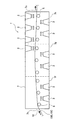
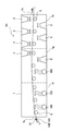
図1は、実施形態にかかる乾燥装置1の概略図である。乾燥装置1は、正極集電部材11の第1面11b(第2面11c)に塗工された正極合材ペースト12を乾燥させる装置である。具体的には、乾燥装置1は、図1に示すように、乾燥炉7と、乾燥炉7内の上部に配置された複数の上部ファン2と、乾燥炉7内の下部に配置された複数の下部ファン3と、乾燥炉7内の中央部に配置された複数のローラ5とを備えている。
Next, an embodiment of the present invention will be described.
FIG. 1 is a schematic view of a
ローラ5は、乾燥炉7の長手方向(図1において左右方向)にわたって間隔を空けて複数配置されており、正極集電部材11の第1面11bに正極合材ペースト12が塗工されたもの(これを第1ペースト塗工部材10Bとする)を、乾燥炉7の入口7bから出口7cに向けて送る。さらに、正極集電部材11の第2面11cに正極合材ペースト12が塗工されたもの(これを第2ペースト塗工部材10Cとする)を、乾燥炉7の入口7bから出口7cに向けて送る。
A plurality of
なお、本実施形態では、第1乾燥工程において、第1ペースト塗工部材10Bが、正極合材ペースト12が塗工された第1面11bを上側に向けて(第2面11cを下側に向けて)、乾燥炉7の入口7bから出口7cに向かって乾燥炉7内を移動する。また、第2乾燥工程において、第2ペースト塗工部材10Cが、正極合材ペースト12が塗工された第2面11cを上側に向けて(第1面11bを下側に向けて)、乾燥炉7の入口7bから出口7cに向かって乾燥炉7内を移動する。
In the present embodiment, in the first drying step, the first
上部ファン2は、乾燥炉7内において上方から下方に向けて熱風を送出する装置である。この上部ファン2は、第1乾燥工程において、乾燥炉7内を移動する第1ペースト塗工部材10Bに対し、第1面11b側(図1において上側)から熱風を当てる。また、第2乾燥工程において、乾燥炉7内を移動する第2ペースト塗工部材10Cに対し、第2面11c側(図1において上側)から熱風を当てる。
The
下部ファン3は、乾燥炉7内において下方から上方に向けて熱風を送出する装置である。この下部ファン3は、第1乾燥工程において、乾燥炉7内を移動する第1ペースト塗工部材10Bに対し、第2面11c側(図1において下側)から熱風を当てる。また、第2乾燥工程において、乾燥炉7内を移動する第2ペースト塗工部材10Cに対し、第1面11b側(図1において下側)から熱風を当てる。
The
なお、本実施形態の乾燥装置1では、下部ファン3を、乾燥炉7の入口7bから出口7cにわたって、合計6個配置している。詳細には、乾燥炉7内を、入口7bから出口7cに向かって3つのゾーン(第1ゾーン7f、第2ゾーン7g、第3ゾーン7h)に分けたとき、下部ファン3は、各ゾーンに2個ずつ、間隔を空けて配置されている。
In the
これにより、第1乾燥工程では、第1面11bに塗工された正極合材ペースト12の乾燥初期段階から乾燥終期にわたって、下部ファン3によって、第1ペースト塗工部材10Bに対し、第2面11c側(図1において下側)から熱風を当てることができる。
同様に、第2乾燥工程では、第2面11cに塗工された正極合材ペースト12の乾燥初期段階から乾燥終期にわたって、下部ファン3によって、第2ペースト塗工部材10Cに対し、第1面11b側(図1において下側)から熱風を当てることができる。
Thereby, in a 1st drying process, it is the 2nd surface with respect to the 1st
Similarly, in the second drying step, the first fan is applied to the second
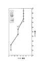
なお、本実施形態の乾燥装置1では、下部ファン3から送出する熱風の温度を、150℃に設定している。また、下部ファン3から送出する熱風の風速は、図2に示す通りである。具体的には、第1ゾーン7fに配置している下部ファン3では、熱風の風速を、7m/secとしている。また、第2ゾーン7gに配置している下部ファン3では、熱風の風速を、5m/secとしている。また、第3ゾーン7hに配置している下部ファン3では、熱風の風速を、3m/secとしている。なお、図2では、ファンの位置を、乾燥炉7の全長を100として示している。すなわち、乾燥炉7の入口7bの位置を0、
出口の位置を100として、ファンの位置を示している。
In the
The position of the fan is indicated with the position of the outlet as 100.
一方、上部ファン2については、合計4個配置しているが、第1ゾーン7fには配置しておらず、第2ゾーン7gの出口7c寄りの位置に1個、第3ゾーン7hに間隔をあけて3個配置している。これにより、本実施形態の第1乾燥工程では、第1面11bに塗工された正極合材ペースト12の乾燥初期段階において、上部ファン2によって、第1ペースト塗工部材10Bに対し、第1面11b側(図1において上側)から熱風を当てないようにしている。
On the other hand, four
具体的には、第1乾燥工程では、第1面11bに塗工された正極合材ペースト12の乾燥中期以降だけ、上部ファン2によって、第1ペースト塗工部材10Bに対し、第1面11b側(図1において上側)から熱風を当るようにしている。同様に、第2乾燥工程において、第2ペースト塗工部材10Cに対して、第2面11cに塗工された正極合材ペースト12の乾燥初期段階では、第2面11c側(図1において上側)から熱風を当てないようにし、乾燥中期以降だけ、第2面11c側(図1において上側)からも熱風を当るようにしている。
Specifically, in the first drying step, the
このようにして、本実施形態では、第1乾燥工程の乾燥初期段階において、正極集電部材11の第1面11bに正極合材ペースト12が塗工された第1ペースト塗工部材10Bに対し、第1面11b側からは熱風を当てることなく、第2面11c側から熱風を当てるようにした。さらに、第2乾燥工程の乾燥初期段階において、正極集電部材11の第2面11cに正極合材ペースト12が塗工された第2ペースト塗工部材10Cに対し、第2面11c側からは熱風を当てることなく、第1面11b側から熱風を当てるようにした。
Thus, in the present embodiment, in the initial drying stage of the first drying process, the first
これにより、本実施形態では、第1乾燥工程の乾燥初期段階において、正極集電部材11の第1面11bに正極合材ペースト12が塗工された第1ペースト塗工部材10Bに対し、第1面11b側から加える熱量よりも第2面11c側から加える熱量を大きくして、正極合材ペースト12を乾燥させることができる。すなわち、第1面11bに塗工した正極合材ペースト12の乾燥初期段階では、正極合材ペースト12を塗工した第1面11b側よりも、正極合材ペースト12を塗工していない第2面11c側から加える熱量を大きくして、正極合材ペースト12を乾燥させることができる。これにより、第1乾燥工程において、第1面11bに塗工された正極合材ペースト12の内部(正極集電部材11側)の乾燥を早めることができ、その結果、正極合材ペースト12が乾燥して形成される電極合材層13にひび割れが生じるのを抑制することができる。
Thus, in the present embodiment, in the initial drying stage of the first drying step, the first
また、第2乾燥工程の乾燥初期段階において、正極集電部材11の第2面11cに正極合材ペースト12が塗工された第2ペースト塗工部材10Cに対し、第2面11c側から加える熱量よりも第1面11b側から加える熱量を大きくして、正極合材ペースト12を乾燥させることができる。すなわち、第2面11cに塗工した正極合材ペースト12の乾燥初期段階では、正極合材ペースト12を塗工した第2面11c側よりも、正極合材ペースト12を塗工していない(既に電極合材層13が形成されている)第1面11b側から加える熱量を大きくして、正極合材ペースト12を乾燥させることができる。これにより、第2乾燥工程においても、第2面11cに塗工された正極合材ペースト12の内部(正極集電部材11側)の乾燥を早めることができ、その結果、正極合材ペースト12を乾燥させて形成される電極合材層13にひび割れが生じるのを抑制することができる。
In addition, in the initial drying stage of the second drying process, the second
なお、本実施形態の乾燥装置1では、上部ファン2から送出する熱風の温度を、150℃に設定している。また、上部ファン2から送出する熱風の風速は、図2に示す通りである。具体的には、第2ゾーン7gに配置している上部ファン2では、熱風の風速を、5m/secとしている。また、第3ゾーン7hに配置している上部ファン2では、
熱風の風速を、3m/secとしている。
In the
The wind speed of hot air is 3 m / sec.
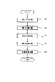
次に、実施形態にかかる電極の製造方法について説明する。図3は、実施形態にかかる電極の製造方法を説明する図であり、正極10を製造する工程のフローチャートである。
まず、ステップS1(第1塗工工程)において、第1面11b及び第2面11cを有する正極集電部材11の第1面11bに、正極合材ペースト12を塗工する(図4参照)。具体的には、図示しない塗工装置を用いて、一定速度で送られてくる正極集電部材11の第1面11bに、正極合材ペースト12を塗工して、第1ペースト塗工部材10Bを作製する(図4参照)。
Next, the manufacturing method of the electrode concerning embodiment is demonstrated. FIG. 3 is a diagram for explaining an electrode manufacturing method according to the embodiment, and is a flowchart of a process for manufacturing the
First, in step S1 (first coating step), the positive
なお、本実施形態では、第1面11bに塗工する正極合材ペースト12の目付量を10mg/cm2 以上(例えば、20mg/cm2 )としている。正極合材ペースト12の目付量を10mg/cm2 以上と大きくすることで、正極10を高容量とし、ひいては電池を高容量にすることができる。
In the present embodiment, the basis weight of the positive
また、正極集電部材11として、厚さ15μmのアルミニウム箔を用いている。また、正極合材ペースト12として、正極活物質(LiNi1/3Co1/3Mn1/3O2)と導電材(アセチレンブラック)とバインダ(PVDF)とを、正極溶媒(NMP)中に分散させてペースト状にした正極合材ペーストを用いている。正極合材ペースト12の固形分率は、60wt%である。また、正極活物質と導電材とバインダとの混合比は、91:6:3(重量比)としている。
Further, an aluminum foil having a thickness of 15 μm is used as the positive electrode current collecting
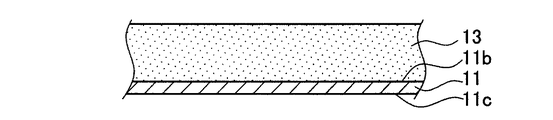
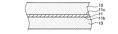
次いで、ステップS2(第1乾燥工程)に進み、正極集電部材11の第1面11bに塗工した正極合材ペースト12を乾燥させる。具体的には、正極集電部材11の第1面11bに正極合材ペースト12を塗工した第1ペースト塗工部材10Bを、一定速度で送りつつ、前述した乾燥装置1の乾燥炉7内を通過させることにより、正極合材ペースト12を乾燥させる。これにより、正極合材ペースト12から正極溶媒(NMP)を取り除いて(蒸発させて)、正極集電部材11の第1面11bに正極合材層13を形成する(図5参照)。
Subsequently, it progresses to step S2 (1st drying process), and the
前述のように、ステップS2(第1乾燥工程)の乾燥初期段階では、第1ペースト塗工部材10Bに対し、第1面11b側から加える熱量よりも第2面11c側から加える熱量を大きくして、正極合材ペースト12を乾燥させる。すなわち、乾燥初期段階では、正極合材ペースト12を塗工した第1面11b側よりも、正極合材ペースト12を塗工していない第2面11c側から加える熱量を大きくして、正極合材ペースト12を乾燥させる。これにより、第1乾燥工程において、第1面11bに塗工された正極合材ペースト12の内部(正極集電部材11側)の乾燥を早めることができ、その結果、正極合材ペースト12を乾燥させて形成される電極合材層13にひび割れが生じるのを抑制することができる。
As described above, in the initial drying stage of step S2 (first drying process), the amount of heat applied from the
また、本実施形態では、第1乾燥工程において、正極合材ペースト12の乾燥時間を、[目付量(mg/cm2 )/乾燥時間(秒)]≧0.3を満たす時間に設定する。例えば、正極集電部材11の第1面11bに塗工した正極合材ペースト12の目付量を20mg/cm2 とした場合、正極合材ペースト12の乾燥時間を66.7秒以内とする。具体的には、正極合材ペースト12の目付量を20mg/cm2 とした場合、第1ペースト塗工部材10Bが、乾燥装置1の乾燥炉7の入口7bを通過してから、出口7cに到達するまでの時間が66.7秒以内となるように、第1ペースト塗工部材10Bの送り速度を設定する。
In the present embodiment, in the first drying step, the drying time of the positive
このように、乾燥時間を短くすることで、正極合材ペースト12の目付量を大きくしつつも、正極10の生産効率を高くすることができる。なお、正極合材ペースト12の乾燥時間を、[目付量(mg/cm2 )/乾燥時間(秒)]≧0.3を満たす時間に短くするにも拘わらず、正極合材ペースト12を適切に乾燥させるために、本実施形態では、乾燥温度(熱風の温度)を150℃と高くしている。
Thus, by shortening the drying time, it is possible to increase the production efficiency of the
ところで、正極合材ペーストの目付量を10mg/cm2 以上と大きくした場合において、特許文献1のように、第1ヒータファン(上部ファン)と第2ヒータファン(下部ファン)とについて、送出される熱風の温度及び風量を等しい値として、第1ペースト塗工部材に対し、第1面側に配置された第1ヒータファン(上部ファン)から熱風を当てると共に、第2面側に配置された第2ヒータファン(下部ファン)からも熱風を当てることによって、正極合材ペーストを乾燥させた場合には、電極合材層にひび割れが生じ易かった。その上、高温で短時間で乾燥させた場合、具体的には、例えば、[目付量(mg/cm2 )/乾燥時間(秒)]≧0.3を満たす乾燥時間で、乾燥温度を150℃程度に設定して、正極合材ペーストを乾燥させた場合には、特にひび割れが生じやすくなる傾向にあった。
By the way, when the basis weight of the positive electrode mixture paste is increased to 10 mg / cm 2 or more, as in
これに対し、本実施形態では、前述のように、第1乾燥工程の乾燥初期段階において、第1ペースト塗工部材10Bに対し、正極集電部材11の第1面11b側から加える熱量よりも第2面11c側から加える熱量を大きくして、正極合材ペースト12を乾燥させる。すなわち、乾燥初期段階では、正極合材ペースト12を塗工した第1面11b側よりも、正極合材ペースト12を塗工していない第2面11c側から加える熱量を大きくして、正極合材ペースト12を乾燥させる。これにより、上述のような目付量及び乾燥時間に設定しても、正極合材ペースト12を乾燥させて形成される電極合材層13にひび割れが生じるのを抑制することができる。
On the other hand, in the present embodiment, as described above, in the initial drying stage of the first drying process, the amount of heat applied to the first
次に、ステップS3(第2塗工工程)に進み、正極合材ペースト12を、正極集電部材11の第2面11cにも塗工する。具体的には、図示しない塗工装置を用いて、ステップS1,S2を経て第1面11bに正極合材層13が形成された正極集電部材11の第2面11cに、正極合材ペースト12を塗工して、第2ペースト塗工部材10Cを作製する(図6参照)。
Next, it progresses to step S3 (2nd coating process), and the
なお、本実施形態では、第2面11cに塗工する正極合材ペースト12の目付量を10mg/cm2 以上(例えば、20mg/cm2 )としている。正極合材ペースト12の目付量を10mg/cm2 以上と大きくすることで、正極10を高容量とし、ひいては電池を高容量にすることができる。
In the present embodiment, the basis weight of the positive
次いで、ステップS4(第2乾燥工程)に進み、正極集電部材11の第2面11cに塗工した正極合材ペースト12を乾燥させる。具体的には、正極集電部材11の第2面11cに正極合材ペースト12を塗工した第2ペースト塗工部材10Cを、一定速度で送りつつ、前述した乾燥装置1の乾燥炉7内を通過させることにより、正極合材ペースト12を乾燥させる。これにより、正極合材ペースト12から正極溶媒(NMP)を取り除いて(蒸発させて)、正極集電部材11の第2面11cにも正極合材層13を形成する(図7参照)。
Then, it progresses to step S4 (2nd drying process), and the
前述のように、ステップS4(第2乾燥工程)の乾燥初期段階では、第2ペースト塗工部材10Cに対し、第2面11c側から加える熱量よりも第1面11b側から加える熱量を大きくして、正極合材ペースト12を乾燥させる。すなわち、乾燥初期段階では、正極合材ペースト12を塗工した第2面11c側よりも、正極合材ペースト12を塗工していない(既に、正極合材層13が形成されている)第1面11b側から加える熱量を大きくして、正極合材ペースト12を乾燥させる。これにより、第2乾燥工程においても、第2面11cに塗工された正極合材ペースト12の内部(正極集電部材11側)の乾燥を早めることができ、その結果、正極合材ペースト12を乾燥させて形成される電極合材層13にひび割れが生じるのを抑制することができる。
As described above, in the initial drying stage of step S4 (second drying step), the amount of heat applied from the
また、本実施形態では、第1乾燥工程と同様に、第2乾燥工程においても、正極合材ペースト12の乾燥時間を、[目付量(mg/cm2 )/乾燥時間(秒)]≧0.3を満たす時間に設定する。例えば、正極集電部材11の第2面11cに塗工した正極合材ペースト12の目付量を20mg/cm2 とした場合、正極合材ペースト12の乾燥時間を66.7秒以内とする。具体的には、正極合材ペースト12の目付量を20mg/cm2 とした場合、第2ペースト塗工部材10Cが、乾燥装置1の乾燥炉7の入口7bを通過してから、出口7cに到達するまでの時間が66.7秒以内となるように、第2ペースト塗工部材10Cの送り速度を設定する。
In the present embodiment, similarly to the first drying step, the drying time of the positive
その後、ステップS5(圧縮成形工程)に進み、正極集電部材11の第1面11b及び第2面11cに形成した正極合材層13を圧縮成形することで、正極板10が完成する(図8参照)。このような製造方法によれば、電極合材層13にひび割れが生じるのを抑制することができる。
上述のようにして製造した正極10は、例えば、リチウムイオン二次電池の正極として用いることができる。
Then, it progresses to step S5 (compression molding process), and the
The
(比較形態)
次に、比較形態について説明する。図10は、比較形態にかかる乾燥装置301の概略図である。乾燥装置301は、実施形態の乾燥装置1と比較して、上部ファン2を第1ゾーン7fにも設け、第2ゾーン7gにも増設している点が異なる。また、上部ファン2と下部ファン3から送出される熱風の風速を全て等しく(具体的には、全て3m/秒)している点も異なる。その他については実施形態の乾燥装置1と同様である。
(Comparison form)
Next, a comparative form will be described. FIG. 10 is a schematic view of a
従って、比較形態の乾燥装置301では、第1乾燥工程において、第1面11bに塗工された正極合材ペースト12の乾燥初期段階から乾燥終期にわたって、第1ペースト塗工部材10Bに対し、下部ファン3によって第2面11c側(図10において下側)から熱風を当てると共に、上部ファン2によって第1面11b側(図10において上側)からも熱風を当てるようにしている。第2乾燥工程においても同様である。このような乾燥方法は、前述の特許文献1と同様である。
Therefore, in the
(乾燥試験)
ここで、比較形態の乾燥装置301を用いて行った、乾燥試験の結果について説明する。この乾燥試験では、正極集電部材11の第1面11bに塗工する正極合材ペースト12の目付量W(mg/cm2)を、5.85、12.5、20、の3種類に異ならせた
サンプルを作製し、それぞれのサンプルについて、乾燥装置301による乾燥時間T(秒)を変動させて、正極合材ペースト12を乾燥させて形成される正極合材層のひび割れの有無を調査した。この結果を図11に示す。なお、図11では、ひび割れが生じたものを×、ひび割れが生じなかったものを○で示している。また、図11で破線で示す直線は、目付量W(mg/cm2)/乾燥時間T(秒)=0.3の関係を満たす直線である。
(Drying test)
Here, the result of the drying test performed using the
図11に示すように、正極合材ペースト12の目付量Wを5.85mg/cm2 とした場合は、乾燥装置301による乾燥時間を18秒として正極合材ペースト12を乾燥させても、ひび割れは発生しなかった。すなわち、目付量W(mg/cm2)/乾燥時間T(秒)=5.85/18=0.325≧0.3としても、正極合材ペースト12を乾燥させた塗膜(正極合材層)にひび割れは発生しなかった。
As shown in FIG. 11, when the basis weight W of the positive
ところが、正極合材ペースト12の目付量Wを12.5mg/cm2 と増大させた場合は、乾燥装置301による乾燥時間を38.5秒として正極合材ペースト12を乾燥させたとき、ひび割れが発生した。すなわち、正極合材ペースト12の目付量Wを12.5mg/cm2 とした場合において、目付量W(mg/cm2)/乾燥時間T(秒)=12.5/38.5=0.325≧0.3に設定して、正極合材ペースト12を乾燥させたところ、正極合材ペースト12を乾燥させた塗膜(正極合材層)にひび割れが発生してしまった。さらに、乾燥時間を徐々に長くしてゆき、ひび割れが生じることなく正極合材ペースト12を乾燥させることができる乾燥時間を調査した。その結果、乾燥時間を180秒以上と長い時間をかけて乾燥させることで、ひび割れが生じることなく正極合材ペースト12を乾燥させることができることがわかった。
However, when the basis weight W of the positive
さらに、正極合材ペースト12の目付量Wを20mg/cm2 と増大させた場合は、乾燥装置301による乾燥時間を61.5秒として正極合材ペースト12を乾燥させたとき、ひび割れが発生した。すなわち、正極合材ペースト12の目付量Wを20mg/cm2 とした場合において、目付量W(mg/cm2)/乾燥時間T(秒)=12.5/
61.5=0.325≧0.3に設定して、正極合材ペースト12を乾燥させたところ、正極合材ペースト12を乾燥させた塗膜(正極合材層)にひび割れが発生してしまった。さらに、乾燥時間を徐々に長くしてゆき、ひび割れが生じることなく正極合材ペースト12を乾燥させることができる乾燥時間を調査した。その結果、乾燥時間を450秒以上と長い時間をかけて乾燥させることで、ひび割れが生じることなく正極合材ペースト12を乾燥させることができることがわかった。
Furthermore, when the basis weight W of the positive
When the positive
これに対し、実施形態の乾燥装置1を用いて、上述の乾燥試験を行ったところ、正極合材ペースト12の目付量Wを5.85mg/cm2 とした場合は、乾燥時間を18秒として正極合材ペースト12を乾燥させたとき、ひび割れは発生しなかった。すなわち、目付量W(mg/cm2)/乾燥時間T(秒)=5.85/18=0.325≧0.3としても、正極合材ペースト12の塗膜(正極合材層)にひび割れは発生しなかった。
On the other hand, when the above-mentioned drying test was performed using the
さらに、実施形態の乾燥装置1を用いて、正極合材ペースト12の目付量Wを12.5mg/cm2 と増大させたサンプルについて、乾燥時間を38.5秒として正極合材ペースト12を乾燥させたときも、ひび割れは発生しなかった。すなわち、正極合材ペースト12の目付量Wを12.5mg/cm2 とした場合において、目付量W(mg/cm2)/乾燥時間T(秒)=12.5/38.5=0.325≧0.3に設定して、正極合材ペースト12を乾燥させた場合でも、正極合材ペースト12を乾燥させた塗膜(正極合材層)にひび割れは発生しなかった。
Furthermore, using the
さらに、実施形態の乾燥装置1を用いて、正極合材ペースト12の目付量Wを20mg/cm2 と増大させたサンプルについて、乾燥時間を61.5秒として正極合材ペースト12を乾燥させたときも、ひび割れは発生しなかった。すなわち、正極合材ペースト12の目付量Wを20mg/cm2 とした場合において、目付量W(mg/cm2)/乾燥時間T(秒)=20/61.5=0.325≧0.3に設定して、正極合材ペースト12を乾燥させた場合でも、正極合材ペースト12を乾燥させた塗膜(正極合材層)にひび割れは発生しなかった。
Furthermore, using the
以上の結果より、正極集電部材の第1面に塗工する正極合材ペーストの目付量Wを10mg/cm2 以上とした場合において、上部ファンと下部ファンとについて、送出される熱風の温度及び風量を等しい値として、第1ペースト塗工部材(電極集電部材の第1面に電極合材ペーストを塗工したもの)に対し、第1面側に配置された上部ファンから熱風を当てると共に、第2面側に配置された下部ファンからも熱風を当てることによって、電極合材ペーストを乾燥させた場合には、電極合材ペーストを乾燥させた電極合材層にひび割れが生じ易くなるといえる。特に、電極合材ペーストの乾燥時間を、[目付量(mg/cm2 )/乾燥時間(秒)]≧0.3を満たす時間に設定して、電極合材ペーストを乾燥させた場合に、ひび割れが生じやすくなるといえる。 From the above results, when the basis weight W of the positive electrode mixture paste applied to the first surface of the positive electrode current collector is 10 mg / cm 2 or more, the temperature of the hot air sent out for the upper fan and the lower fan Then, hot air is applied from the upper fan arranged on the first surface side to the first paste coating member (the electrode current collector member coated with the electrode mixture paste) with the same air volume. At the same time, when the electrode mixture paste is dried by applying hot air from the lower fan disposed on the second surface side, cracks are likely to occur in the electrode mixture layer from which the electrode mixture paste is dried. I can say that. In particular, when the electrode mixture paste is dried by setting the drying time of the electrode mixture paste to a time that satisfies [weight per unit area (mg / cm 2 ) / drying time (seconds)] ≧ 0.3, It can be said that cracks are likely to occur.
これに対し、正極集電部材の第1面に塗工する正極合材ペーストの目付量Wを10mg/cm2 以上とした場合において、実施形態のように、乾燥初期段階において、第1ペースト塗工部材10Bに対し、正極集電部材11の第1面11b側から加える熱量よりも第2面11c側から加える熱量を大きくして、正極合材ペースト12を乾燥させることで、正極合材ペースト12を乾燥させて形成される電極合材層13にひび割れが生じるのを抑制することができるといえる。すなわち、乾燥初期段階では、正極合材ペースト12を塗工した第1面11b側よりも、正極合材ペースト12を塗工していない第2面11c側から加える熱量を大きくして、正極合材ペースト12を乾燥させることで、電極合材層13にひび割れが生じるのを抑制することができるといえる。この方法は、特に、電極合材ペーストの乾燥時間を、[目付量(mg/cm2 )/乾燥時間(秒)]≧0.3を満たす時間に設定して、電極合材ペーストを乾燥させた場合に有効であるといえる。
On the other hand, when the basis weight W of the positive electrode mixture paste applied to the first surface of the positive electrode current collecting member is 10 mg / cm 2 or more, the first paste coating is applied at the initial stage of drying as in the embodiment. By increasing the amount of heat applied from the
なお、上述の乾燥試験を、第2乾燥工程に適用した場合も、同様な結果となった。すなわち、正極集電部材11の第1面11bに正極合材ペースト12を塗工し、乾燥させた後、正極集電部材11の第2面11cに正極合材ペースト12を塗工した各サンプルについて、上述の乾燥試験を行ったところ、同様な結果となった。
The same result was obtained when the above-described drying test was applied to the second drying step. That is, each sample in which the positive
(変形形態)
次に、本発明の変形形態について説明する。
本変形形態の乾燥装置101は、図9に示すように、実施形態の乾燥装置1について、第1ゾーン7fの2つの下部ファン3、及び、第2ゾーン7gの入口7b側の下部ファン3を、赤外線ヒータ103に代えたものである。従って、本変形形態の乾燥装置101を用いることで、第1乾燥工程の乾燥初期段階において、正極集電部材11の第1面11bに正極合材ペースト12が塗工された第1ペースト塗工部材10Bに対し、第2面11c側から赤外線を照射することができる。また、第2乾燥工程の乾燥初期段階においても、正極集電部材11の第2面11cに正極合材ペースト12が塗工された第2ペースト塗工部材10Cに対し、第1面11b側から赤外線を照射することができる。
(Deformation)
Next, modifications of the present invention will be described.
As shown in FIG. 9, the
本変形形態では、第1乾燥工程の乾燥初期段階において、正極集電部材11の第1面11bに正極合材ペースト12が塗工された第1ペースト塗工部材10Bに対し、第1面11b側から赤外線を照射することなく(熱風を当てることもなく)、第2面11c側から赤外線を照射して加熱するようにした。さらに、第2乾燥工程の乾燥初期段階において、正極集電部材11の第2面11cに正極合材ペースト12が塗工された第2ペースト塗工部材10Cに対し、第2面11c側から赤外線を照射することなく(熱風を当てることもなく)、第1面11b側から赤外線を照射して加熱するようにした。
In this modification, in the initial drying stage of the first drying process, the
これにより、本変形形態でも、実施形態と同様に、第1乾燥工程の乾燥初期段階において、正極集電部材11の第1面11bに正極合材ペースト12が塗工された第1ペースト塗工部材10Bに対し、第1面11b側から加える熱量よりも第2面11c側から加える熱量を大きくして、正極合材ペースト12を乾燥させることができる。すなわち、第1面11bに塗工した正極合材ペースト12の乾燥初期段階では、正極合材ペースト12を塗工した第1面11b側よりも、正極合材ペースト12を塗工していない第2面11c側から加える熱量を大きくして、正極合材ペースト12を乾燥させることができる。これにより、第1乾燥工程において、第1面11bに塗工された正極合材ペースト12の内部(正極集電部材11側)の乾燥を早めることができ、その結果、正極合材ペースト12を乾燥させて形成される電極合材層13にひび割れが生じるのを抑制することができる。第2乾燥工程においても同様に、正極集電部材11の第2面11cに形成される電極合材層13にひび割れが生じるのを抑制することができる。
Thereby, also in this modified embodiment, as in the embodiment, the first paste application in which the positive
以上において、本発明を実施形態及び変形形態に即して説明したが、本発明は上記実施形態等に限定されるものではなく、その要旨を逸脱しない範囲で、適宜変更して適用できることは言うまでもない。 In the above, the present invention has been described with reference to the embodiments and modifications. However, the present invention is not limited to the above-described embodiments and the like, and it is needless to say that the present invention can be appropriately modified and applied without departing from the gist thereof. Yes.
例えば、実施形態等では、本発明の電極の製造方法を、正極の製造方法に適用した例で説明した。しかしながら、本発明の電極の製造方法は、負極の製造方法にも適用することができる。 For example, in the embodiments and the like, the example of applying the electrode manufacturing method of the present invention to the positive electrode manufacturing method has been described. However, the electrode manufacturing method of the present invention can also be applied to a negative electrode manufacturing method.
1,101 乾燥装置
2 上部ファン
3 下部ファン
7 乾燥炉
10 正極(電極)
10B 第1ペースト塗工部材
10C 第2ペースト塗工部材
11 正極集電部材(電極集電部材)
11b 正極集電部材の第1面(電極集電部材の第1面)
11c 正極集電部材の第2面(電極集電部材の第2面)
12 正極合材ペースト(電極合材ペースト)
13 正極合材層(電極合材層)
103 赤外線ヒータ
1,101
10B 1st
11b 1st surface of positive electrode current collection member (1st surface of electrode current collection member)
11c 2nd surface of positive electrode current collection member (2nd surface of electrode current collection member)
12 Positive electrode material paste (electrode material paste)
13 Positive electrode mixture layer (electrode mixture layer)
103 Infrared heater
Claims (8)
上記第1面に塗工した上記電極合材ペーストを乾燥させる第1乾燥工程と、を備える
電極の製造方法において、
上記第1乾燥工程は、
乾燥初期段階において、上記電極集電部材の上記第1面に上記電極合材ペーストが塗工された第1ペースト塗工部材に対し、上記第1面側から加える熱量よりも上記第2面側から加える熱量を大きくして、上記電極合材ペーストを乾燥させる
電極の製造方法。 A first coating step of applying an electrode mixture paste to the first surface of the electrode current collector having the first surface and the second surface;
In the manufacturing method of an electrode provided with the 1st drying process of drying the electrode mixture paste applied to the 1st side,
The first drying step includes
In the initial drying stage, the second surface side is more than the amount of heat applied from the first surface side to the first paste coated member in which the electrode mixture paste is coated on the first surface of the electrode current collecting member. The manufacturing method of the electrode which enlarges the calorie | heat amount applied from and dries the said electrode compound paste.
前記第1乾燥工程は、
前記乾燥初期段階において、前記第1ペースト塗工部材に対し、前記第2面側から熱風を当てる
電極の製造方法。 It is a manufacturing method of the electrode according to claim 1, Comprising:
The first drying step includes
In the drying initial stage, a method of manufacturing an electrode in which hot air is applied to the first paste coating member from the second surface side.
前記第1乾燥工程は、
前記乾燥初期段階において、前記第1ペースト塗工部材に対し、前記第2面側から赤外線を照射する
電極の製造方法。 It is a manufacturing method of the electrode according to claim 1, Comprising:
The first drying step includes
The manufacturing method of the electrode which irradiates infrared rays from the said 2nd surface side with respect to a said 1st paste coating member in the said drying initial stage.
前記第1塗工工程では、前記第1面に塗工する前記電極合材ペーストの目付量を10mg/cm2 以上とし、
前記第1乾燥工程では、上記電極合材ペーストの乾燥時間を、[目付量(mg/cm2 )/乾燥時間(秒)]≧0.3を満たす時間に設定する
電極の製造方法。 It is a manufacturing method of the electrode according to any one of claims 1 to 3,
In the first coating step, the basis weight of the electrode mixture paste applied to the first surface is 10 mg / cm 2 or more,
In the first drying step, a method for producing an electrode, wherein the drying time of the electrode mixture paste is set to a time satisfying [weight per unit area (mg / cm 2 ) / drying time (seconds)] ≧ 0.3.
前記第1乾燥工程の後、前記電極集電部材の前記第2面に電極合材ペーストを塗工する第2塗工工程と、
上記第2面に塗工した上記電極合材ペーストを乾燥させる第2乾燥工程と、を備え、
上記第2乾燥工程は、
乾燥初期段階において、上記電極集電部材の上記第2面に上記電極合材ペーストが塗工された第2ペースト塗工部材に対し、上記第2面側から加える熱量よりも前記第1面側から加える熱量を大きくして、上記電極合材ペーストを乾燥させる
電極の製造方法。 It is a manufacturing method of the electrode according to any one of claims 1 to 4,
After the first drying step, a second coating step of applying an electrode mixture paste to the second surface of the electrode current collector;
A second drying step of drying the electrode mixture paste applied to the second surface,
The second drying step
In the initial stage of drying, the first surface side of the second paste coated member in which the electrode mixture paste is coated on the second surface of the electrode current collecting member than the amount of heat applied from the second surface side. The manufacturing method of the electrode which enlarges the calorie | heat amount applied from and dries the said electrode compound paste.
前記第2乾燥工程は、
前記乾燥初期段階において、前記第2ペースト塗工部材に対し、前記第1面側から熱風を当てる
電極の製造方法。 It is a manufacturing method of the electrode according to claim 5,
The second drying step includes
An electrode manufacturing method in which hot air is applied from the first surface side to the second paste coating member in the initial drying stage.
前記第2乾燥工程は、
前記乾燥初期段階において、前記第2ペースト塗工部材に対し、前記第1面側から赤外線を照射する
電極の製造方法。 It is a manufacturing method of the electrode according to claim 5,
The second drying step includes
The manufacturing method of the electrode which irradiates infrared rays from the said 1st surface side with respect to a said 2nd paste coating member in the said drying initial stage.
前記第2塗工工程では、前記第2面に塗工する前記電極合材ペーストの目付量を10mg/cm2 以上とし、
前記第2乾燥工程では、上記電極合材ペーストの乾燥時間を、[目付量(mg/cm2 )/乾燥時間(秒)]≧0.3を満たす時間に設定する
電極の製造方法。 It is a manufacturing method of the electrode according to any one of claims 5 to 7,
In the second coating step, the basis weight of the electrode mixture paste applied to the second surface is 10 mg / cm 2 or more,
In the second drying step, a method for producing an electrode, wherein the drying time of the electrode mixture paste is set to a time satisfying [weight per unit area (mg / cm 2 ) / drying time (seconds)] ≧ 0.3.
Priority Applications (3)
| Application Number | Priority Date | Filing Date | Title |
|---|---|---|---|
| JP2011110744A JP2012243473A (en) | 2011-05-17 | 2011-05-17 | Manufacturing method of electrode |
| US13/471,681 US20120295037A1 (en) | 2011-05-17 | 2012-05-15 | Method for manufacturing electrodes |
| CN2012101535298A CN102790200A (en) | 2011-05-17 | 2012-05-17 | Method for manufacturing electrodes |
Applications Claiming Priority (1)
| Application Number | Priority Date | Filing Date | Title |
|---|---|---|---|
| JP2011110744A JP2012243473A (en) | 2011-05-17 | 2011-05-17 | Manufacturing method of electrode |
Publications (1)
| Publication Number | Publication Date |
|---|---|
| JP2012243473A true JP2012243473A (en) | 2012-12-10 |
Family
ID=47155542
Family Applications (1)
| Application Number | Title | Priority Date | Filing Date |
|---|---|---|---|
| JP2011110744A Pending JP2012243473A (en) | 2011-05-17 | 2011-05-17 | Manufacturing method of electrode |
Country Status (3)
| Country | Link |
|---|---|
| US (1) | US20120295037A1 (en) |
| JP (1) | JP2012243473A (en) |
| CN (1) | CN102790200A (en) |
Cited By (7)
| Publication number | Priority date | Publication date | Assignee | Title |
|---|---|---|---|---|
| WO2014103786A1 (en) * | 2012-12-28 | 2014-07-03 | 日本碍子株式会社 | Method for drying electrode coating film of battery and drying furnace |
| JP2014139896A (en) * | 2013-01-21 | 2014-07-31 | Toyota Industries Corp | Apparatus and method for manufacturing electric storage device |
| JP2015018727A (en) * | 2013-07-12 | 2015-01-29 | トヨタ自動車株式会社 | Drying apparatus, drying method, and battery manufacturing method |
| JP2015191779A (en) * | 2014-03-28 | 2015-11-02 | Necエナジーデバイス株式会社 | Secondary battery electrode and secondary battery manufacturing method |
| WO2023249348A1 (en) * | 2022-06-23 | 2023-12-28 | 주식회사 에스에프에이 | Hybrid drying system for manufacturing secondary battery electrode |
| WO2023249349A1 (en) * | 2022-06-23 | 2023-12-28 | 주식회사 에스에프에이 | Hybrid drying system for manufacturing secondary battery electrode |
| US12494474B2 (en) | 2020-10-12 | 2025-12-09 | Lg Energy Solution, Ltd. | Electrode drying method capable of suppressing binder swelling and electrode drying system using same |
Families Citing this family (4)
| Publication number | Priority date | Publication date | Assignee | Title |
|---|---|---|---|---|
| JP5655769B2 (en) | 2011-12-09 | 2015-01-21 | トヨタ自動車株式会社 | Electrode manufacturing method |
| JP6032160B2 (en) * | 2013-09-02 | 2016-11-24 | トヨタ自動車株式会社 | Method for manufacturing electrode of secondary battery by ESD method |
| JP6487729B2 (en) * | 2015-03-11 | 2019-03-20 | 株式会社Screenホールディングス | Substrate processing apparatus, coating film forming system, substrate processing method and coating film forming method |
| KR102075098B1 (en) * | 2017-01-03 | 2020-02-07 | 주식회사 엘지화학 | Manufacturing system for secondary battery electrode with scratch tester |
Citations (8)
| Publication number | Priority date | Publication date | Assignee | Title |
|---|---|---|---|---|
| JPH05129021A (en) * | 1991-11-01 | 1993-05-25 | Sony Corp | Device for manufacturing battery electrode |
| JP2001307716A (en) * | 2000-02-16 | 2001-11-02 | Nisshinbo Ind Inc | Multilayer electrode structure, battery using the same, electric double layer capacitor, and method for manufacturing the same |
| JP2002056841A (en) * | 2000-08-11 | 2002-02-22 | Nec Mobile Energy Kk | Method of manufacturing electrode |
| JP2003178752A (en) * | 2001-12-07 | 2003-06-27 | Toyota Motor Corp | Evaluation method for drying of sheet electrode |
| JP2006073234A (en) * | 2004-08-31 | 2006-03-16 | Sanyo Electric Co Ltd | Method of manufacturing non-aqueous electrolyte secondary battery and electrode plate dryer for non-aqueous electrolyte secondary battery |
| JP2008108649A (en) * | 2006-10-27 | 2008-05-08 | Toyota Motor Corp | Method for manufacturing positive electrode for lithium secondary battery for vehicle |
| JP2009193932A (en) * | 2008-02-18 | 2009-08-27 | Asahi Kasei E-Materials Corp | Manufacturing method of electrode |
| JP2009266660A (en) * | 2008-04-25 | 2009-11-12 | Nec Tokin Corp | Manufacturing method of electrode plate for lithium ion secondary battery |
Family Cites Families (8)
| Publication number | Priority date | Publication date | Assignee | Title |
|---|---|---|---|---|
| US2673230A (en) * | 1949-01-08 | 1954-03-23 | Joseph B Brennan | Battery separator |
| US3630802A (en) * | 1970-07-13 | 1971-12-28 | Theodore J Dettling | Method and apparatus for producing a coated substrate and a laminated product |
| US4500896A (en) * | 1983-01-25 | 1985-02-19 | Ricoh Company, Ltd. | Heat-sensitive recording medium affording patterns with different colors |
| US4822643A (en) * | 1987-06-30 | 1989-04-18 | Minnesota Mining And Manufacturing Company | Thermal transfer imaging system |
| US4816098A (en) * | 1987-07-16 | 1989-03-28 | Texas Instruments Incorporated | Apparatus for transferring workpieces |
| JPH0838997A (en) * | 1994-07-29 | 1996-02-13 | Tokin Corp | How to apply paste |
| US5621983A (en) * | 1996-03-29 | 1997-04-22 | Minnesota Mining And Manufacturing Company | Apparatus and method for deckeling excess air when drying a coating on a substrate |
| AU2003257608A1 (en) * | 2002-08-21 | 2004-03-11 | National Institute Of Advanced Industrial Science And Technology | Inorganic compound containing active oxygen and process for producing the same |
-
2011
- 2011-05-17 JP JP2011110744A patent/JP2012243473A/en active Pending
-
2012
- 2012-05-15 US US13/471,681 patent/US20120295037A1/en not_active Abandoned
- 2012-05-17 CN CN2012101535298A patent/CN102790200A/en active Pending
Patent Citations (8)
| Publication number | Priority date | Publication date | Assignee | Title |
|---|---|---|---|---|
| JPH05129021A (en) * | 1991-11-01 | 1993-05-25 | Sony Corp | Device for manufacturing battery electrode |
| JP2001307716A (en) * | 2000-02-16 | 2001-11-02 | Nisshinbo Ind Inc | Multilayer electrode structure, battery using the same, electric double layer capacitor, and method for manufacturing the same |
| JP2002056841A (en) * | 2000-08-11 | 2002-02-22 | Nec Mobile Energy Kk | Method of manufacturing electrode |
| JP2003178752A (en) * | 2001-12-07 | 2003-06-27 | Toyota Motor Corp | Evaluation method for drying of sheet electrode |
| JP2006073234A (en) * | 2004-08-31 | 2006-03-16 | Sanyo Electric Co Ltd | Method of manufacturing non-aqueous electrolyte secondary battery and electrode plate dryer for non-aqueous electrolyte secondary battery |
| JP2008108649A (en) * | 2006-10-27 | 2008-05-08 | Toyota Motor Corp | Method for manufacturing positive electrode for lithium secondary battery for vehicle |
| JP2009193932A (en) * | 2008-02-18 | 2009-08-27 | Asahi Kasei E-Materials Corp | Manufacturing method of electrode |
| JP2009266660A (en) * | 2008-04-25 | 2009-11-12 | Nec Tokin Corp | Manufacturing method of electrode plate for lithium ion secondary battery |
Cited By (9)
| Publication number | Priority date | Publication date | Assignee | Title |
|---|---|---|---|---|
| WO2014103786A1 (en) * | 2012-12-28 | 2014-07-03 | 日本碍子株式会社 | Method for drying electrode coating film of battery and drying furnace |
| JP2014130742A (en) * | 2012-12-28 | 2014-07-10 | Ngk Insulators Ltd | Method for drying battery electrode coating film and drying furnace |
| JP2014139896A (en) * | 2013-01-21 | 2014-07-31 | Toyota Industries Corp | Apparatus and method for manufacturing electric storage device |
| JP2015018727A (en) * | 2013-07-12 | 2015-01-29 | トヨタ自動車株式会社 | Drying apparatus, drying method, and battery manufacturing method |
| US10396344B2 (en) | 2013-07-12 | 2019-08-27 | Toyota Jidosha Kabushiki Kaisha | Drying method and battery manufacturing method |
| JP2015191779A (en) * | 2014-03-28 | 2015-11-02 | Necエナジーデバイス株式会社 | Secondary battery electrode and secondary battery manufacturing method |
| US12494474B2 (en) | 2020-10-12 | 2025-12-09 | Lg Energy Solution, Ltd. | Electrode drying method capable of suppressing binder swelling and electrode drying system using same |
| WO2023249348A1 (en) * | 2022-06-23 | 2023-12-28 | 주식회사 에스에프에이 | Hybrid drying system for manufacturing secondary battery electrode |
| WO2023249349A1 (en) * | 2022-06-23 | 2023-12-28 | 주식회사 에스에프에이 | Hybrid drying system for manufacturing secondary battery electrode |
Also Published As
| Publication number | Publication date |
|---|---|
| CN102790200A (en) | 2012-11-21 |
| US20120295037A1 (en) | 2012-11-22 |
Similar Documents
| Publication | Publication Date | Title |
|---|---|---|
| JP2012243473A (en) | Manufacturing method of electrode | |
| JP5842407B2 (en) | Method for producing lithium ion secondary battery | |
| JP5325332B1 (en) | Battery electrode coating film drying method and drying furnace | |
| JP6067636B2 (en) | Method for producing electrode for lithium ion secondary battery | |
| JP7480430B2 (en) | Electrode and manufacturing method thereof | |
| JP6780601B2 (en) | Electrode sheet manufacturing method | |
| JP6874617B2 (en) | Negative electrode sheet manufacturing method | |
| JP5640996B2 (en) | Battery electrode manufacturing method and battery electrode | |
| CN105655546B (en) | Method of the manufacture for the anode of lithium rechargeable battery | |
| CN112768691A (en) | Coating agent, coating modified graphite negative electrode material, preparation method and application thereof, and lithium ion battery | |
| JP6380397B2 (en) | Method for producing granulated particles for electrochemical element, electrode for electrochemical element, and electrochemical element | |
| CN107785582A (en) | Positive plate and secondary cell | |
| JP7700280B2 (en) | Coating slurry, coated separator, separator manufacturing method, and battery | |
| JP5259875B1 (en) | Battery electrode coating film drying method and drying furnace | |
| JP2023504346A (en) | ELECTRODE DRYING METHOD AND ELECTRODE DRYING SYSTEM USING THE SAME | |
| US20250096414A1 (en) | Coating slurry, separator, preparation method for separator and battery | |
| JP2011023129A (en) | Method of manufacturing positive electrode plate for nonaqueous secondary battery, and manufacturing device therefor | |
| JP2015173035A (en) | Method for manufacturing electrode for nonaqueous electrolyte secondary battery and manufacturing device | |
| TW477084B (en) | Wet-on-wet coating process for the production of composite articles which are suitable for use in lithium ion batteries | |
| JP2009037893A (en) | Method for producing negative electrode plate for non-aqueous secondary battery | |
| JP2015185250A (en) | Manufacturing method of negative electrode for nonaqueous electrolyte secondary batteries | |
| KR101279174B1 (en) | Electrode structure of secondary battery and manufacturing method for electrode of secondary battery | |
| CN109390560B (en) | Method for producing negative electrode | |
| KR101465018B1 (en) | Method of manufacturing cathode of lithium primary battery using kneading mixing | |
| CN110931723A (en) | Preparation method of 0D/2D nano-layered structure Si-RGO composite material |
Legal Events
| Date | Code | Title | Description |
|---|---|---|---|
| A977 | Report on retrieval |
Free format text: JAPANESE INTERMEDIATE CODE: A971007 Effective date: 20130823 |
|
| A131 | Notification of reasons for refusal |
Free format text: JAPANESE INTERMEDIATE CODE: A131 Effective date: 20130827 |
|
| A521 | Request for written amendment filed |
Free format text: JAPANESE INTERMEDIATE CODE: A523 Effective date: 20131009 |
|
| A131 | Notification of reasons for refusal |
Free format text: JAPANESE INTERMEDIATE CODE: A131 Effective date: 20140624 |
|
| A02 | Decision of refusal |
Free format text: JAPANESE INTERMEDIATE CODE: A02 Effective date: 20141111 |