JP2012243631A - Rotary electronic component - Google Patents
Rotary electronic component Download PDFInfo
- Publication number
- JP2012243631A JP2012243631A JP2011113635A JP2011113635A JP2012243631A JP 2012243631 A JP2012243631 A JP 2012243631A JP 2011113635 A JP2011113635 A JP 2011113635A JP 2011113635 A JP2011113635 A JP 2011113635A JP 2012243631 A JP2012243631 A JP 2012243631A
- Authority
- JP
- Japan
- Prior art keywords
- shaft
- rotating body
- guide groove
- vertical guide
- engaging portion
- Prior art date
- Legal status (The legal status is an assumption and is not a legal conclusion. Google has not performed a legal analysis and makes no representation as to the accuracy of the status listed.)
- Granted
Links
- 230000002093 peripheral effect Effects 0.000 claims abstract description 29
- 230000002265 prevention Effects 0.000 claims description 18
- 238000001514 detection method Methods 0.000 description 23
- 238000000034 method Methods 0.000 description 13
- 239000000758 substrate Substances 0.000 description 10
- 238000003780 insertion Methods 0.000 description 9
- 230000037431 insertion Effects 0.000 description 9
- 239000002184 metal Substances 0.000 description 5
- 239000000463 material Substances 0.000 description 4
- 229920003002 synthetic resin Polymers 0.000 description 4
- 239000000057 synthetic resin Substances 0.000 description 4
- 230000005489 elastic deformation Effects 0.000 description 2
- 238000000465 moulding Methods 0.000 description 2
- 229920005668 polycarbonate resin Polymers 0.000 description 2
- 239000004431 polycarbonate resin Substances 0.000 description 2
- 229920005989 resin Polymers 0.000 description 2
- 239000011347 resin Substances 0.000 description 2
- 229910000906 Bronze Inorganic materials 0.000 description 1
- OAICVXFJPJFONN-UHFFFAOYSA-N Phosphorus Chemical compound [P] OAICVXFJPJFONN-UHFFFAOYSA-N 0.000 description 1
- 238000005452 bending Methods 0.000 description 1
- 239000010974 bronze Substances 0.000 description 1
- KUNSUQLRTQLHQQ-UHFFFAOYSA-N copper tin Chemical compound [Cu].[Sn] KUNSUQLRTQLHQQ-UHFFFAOYSA-N 0.000 description 1
- 238000010586 diagram Methods 0.000 description 1
- 230000000694 effects Effects 0.000 description 1
- 239000013013 elastic material Substances 0.000 description 1
- 238000012986 modification Methods 0.000 description 1
- 230000004048 modification Effects 0.000 description 1
- 230000003287 optical effect Effects 0.000 description 1
- 230000035807 sensation Effects 0.000 description 1
- 229910001220 stainless steel Inorganic materials 0.000 description 1
- 239000010935 stainless steel Substances 0.000 description 1
Images







Landscapes
- Switch Cases, Indication, And Locking (AREA)
- Rotary Switch, Piano Key Switch, And Lever Switch (AREA)
Abstract
【課題】高さを高くしなくても容易にシャフトの押圧ストロークを長くできる回転式電子部品を提供する。
【解決手段】ケース10,150内に回転自在に回転体80を収納する。シャフト110の下部を回転体80のシャフト軸支穴85に挿入する。シャフト110の下部外周に設けた係合部117を、シャフト軸支穴85内周面の上下にわたって設けた上下方向ガイド溝89に挿入してシャフト軸支穴85の下部に露出させて所定角度回転し、さらにシャフト軸支穴85内周面に設けた終端付上下方向ガイド溝91に係合部117を上向きに挿入することによって、シャフト110を回転体80と一体に回転自在且つ回転体80内で所定ストローク上下動自在に取り付ける。回転体80に、シャフト110の係合部117が終端付上下方向ガイド溝91から下方に向けて露出した際に上下方向ガイド溝89側に向かって反転するのを阻止する回転防止部100を設ける。
【選択図】図10A rotary electronic component capable of easily extending a pressing stroke of a shaft without increasing the height is provided.
A rotating body 80 is housed rotatably in cases 10 and 150. The lower part of the shaft 110 is inserted into the shaft support hole 85 of the rotating body 80. The engaging portion 117 provided on the lower outer periphery of the shaft 110 is inserted into a vertical guide groove 89 provided over the inner peripheral surface of the shaft shaft support hole 85 so as to be exposed to the lower portion of the shaft shaft support hole 85 and rotated by a predetermined angle. Further, by inserting the engaging portion 117 upward into a vertical guide groove 91 with a terminal end provided on the inner peripheral surface of the shaft shaft support hole 85, the shaft 110 can be rotated integrally with the rotary body 80 and can be rotated within the rotary body 80. Attach it up and down with a predetermined stroke. The rotating body 80 is provided with an anti-rotation portion 100 that prevents the engaging portion 117 of the shaft 110 from reversing toward the vertical guide groove 89 when the engaging portion 117 of the shaft 110 is exposed downward from the vertical guide groove 91 with a terminal end. .
[Selection] Figure 10
Description
本発明は、回転式電子部品に関するものである。 The present invention relates to a rotary electronic component.
従来、ケース上面に設けた筒状の軸受内に回動自在にシャフトを挿入し、このシャフトをケース内部に収納した回転体に結合し、シャフトを回転することで回転体を一体に回転してケース内に設置した回転式の検出手段(例えば回転式スイッチ)を操作すると共に、シャフトを真下に押圧することでシャフトのみが下降して回転体の下部に設置した押圧式の検出手段(例えば押圧式スイッチ)を操作する構造の回転式電子部品がある(例えば特許文献1の図1や特許文献2の図2参照)。
Conventionally, a shaft is rotatably inserted into a cylindrical bearing provided on the upper surface of the case, the shaft is coupled to a rotating body housed in the case, and the rotating body is rotated integrally by rotating the shaft. A rotary detection means (for example, a rotary switch) installed in the case is operated, and a pressure detection means (for example, a press) is installed at the lower part of the rotating body by lowering only the shaft by pressing the shaft directly below. There is a rotary electronic component having a structure for operating a switch (for example, see FIG. 1 of
ここで特許文献1の構造の回転式電子部品においては、その図1,図2に示すように、ケース(10)の貫通孔(11)に挿入したシャフト(30)の先端側部分にワッシャ(100)を取り付けることによって、ケース(10)に対してシャフト(30)を所定距離上下動自在に取り付けている。しかしながら特許文献1の構造では、ワッシャ(100)が必要となって部品点数が増加するばかりか、ワッシャ(100)の取付作業が煩雑であった。
Here, in the rotary electronic component having the structure of
これに対して特許文献2の構造の回転式電子部品は、その図1,図2に示すように、シャフト(10)の外周に設けた係合部(17)をシャフト軸支穴(43)の内周に設けた上下方向溝(45)に挿入し、次にシャフト(10)を回転して係合部(17)を終端付上下方向溝(49)に至らせ、次にシャフト(10)を上方向に移動することで回転型物(30)に対してシャフト(10)を所定距離上下動自在に取り付けている。このように構成すれば特許文献1のワッシャを取り付けなくてもシャフト(10)が回転型物(30)から外れることはなく、部品点数を減少できるばかりか、組立作業も容易になる。
On the other hand, in the rotary electronic component having the structure of
しかしながら特許文献2の構造の回転式電子部品においては、シャフト(10)の上下方向のストロークをそれほど長くすることができなかった。即ち引用文献2の場合、回転型物(30)に組み込んだシャフト(10)を回転型物(30)に対して下降した際に、もしその下降寸法が長いと、係合部(17)が終端付上下方向溝(49)から下方向に完全に抜け出てしまい、シャフト(10)が回転型物(30)から外れてしまう恐れがあった。一方シャフト(10)のストロークを大きくするのであれば前記終端付上下方向溝(49)の長さを長く取ればよい。しかしながらそうすると回転型物(30)に対してシャフト(10)が上方向に大きく引き出され、ストロークを大きくした寸法だけ電子部品の高さ寸法が高くなってしまう。
However, in the rotary electronic component having the structure of
本発明は上述の点に鑑みてなされたものでありその目的は、高さを高くしなくても容易にシャフトの押圧ストロークを長くすることができる回転式電子部品を提供することにある。 The present invention has been made in view of the above points, and an object of the present invention is to provide a rotary electronic component that can easily increase the pressing stroke of the shaft without increasing the height.
本願請求項1に記載の発明は、ケースと、前記ケース内に回転自在に収納される回転体と、下部が前記回転体に設けたシャフト軸支穴に取り付けられ上部が前記ケース上面から突出するシャフトとを具備し、前記シャフト下部の外周に設けた係合部を、前記回転体のシャフト軸支穴内周面の上下にわたって設けた上下方向ガイド溝にシャフト軸支穴の上部から挿入してシャフト軸支穴の下部に露出させて所定角度回転し、さらに前記回転体のシャフト軸支穴内周面に設けた終端付上下方向ガイド溝に前記係合部を上向きに挿入することによって、前記シャフトを回転体と一体に回転自在且つ回転体内で所定ストローク上下動自在となるように取り付けてなる回転式電子部品において、前記回転体には、前記シャフトの係合部が前記終端付上下方向ガイド溝から下方に向けて露出した際に前記上下方向ガイド溝側に向かって反転するのを阻止する回転防止部が設けられていることを特徴とする回転式電子部品にある。 According to the first aspect of the present invention, a case, a rotating body that is rotatably accommodated in the case, a lower portion is attached to a shaft shaft support hole provided in the rotating body, and an upper portion projects from the upper surface of the case. And an engaging portion provided on an outer periphery of the lower portion of the shaft is inserted into an upper and lower guide groove provided on the upper and lower sides of an inner peripheral surface of the shaft shaft of the rotating body from above the shaft shaft supporting hole. The shaft is exposed to the lower portion of the shaft support hole, rotated by a predetermined angle, and the engaging portion is inserted upward into a vertical guide groove with a terminal provided on the inner peripheral surface of the shaft shaft support hole of the rotating body. In a rotary electronic component attached so as to be rotatable integrally with a rotating body and to be movable up and down by a predetermined stroke within the rotating body, the engaging portion of the shaft is attached to the rotating body with the above-mentioned end-up and bottom ends. In a rotary electronic component, characterized in that the rotation prevention portion for preventing the reversed the toward the vertical guide groove side from direction guide groove when exposed downward is provided.
本願請求項2に記載の発明は、請求項1に記載の回転式電子部品であって、前記回転防止部は、前記上下方向ガイド溝に挿入してその下部から露出した前記係合部を回転する際の係合部の外周面に対向する回転体の内周面に、内側向きに突出する突出部を設けることによって構成され、前記係合部が前記回転防止部を押圧しながら回転して乗り越えることで前記係合部の前記上下方向ガイド溝側への反転を阻止することを特徴とする回転式電子部品にある。
The invention according to
本願請求項3に記載の発明は、請求項2に記載の回転式電子部品であって、内側に前記回転防止部を設けた前記回転体の側壁部に、半径方向外方に向かう弾性を持たせたことを特徴とする回転式電子部品にある。
The invention according to
本願請求項4に記載の発明は、請求項3に記載の回転式電子部品であって、前記回転防止部は、前記上下方向ガイド溝側から前記終端付上下方向ガイド溝側に向かって徐々にその突出高さを高くする形状に形成されていることを特徴とする回転式電子部品にある。
The invention according to claim 4 of the present application is the rotary electronic component according to
請求項1に記載の発明によれば、終端付上下方向ガイド溝の長さを長くすることなく(即ち回転式電子部品の高さ寸法を高くすることなく)、容易にシャフトの押圧ストロークを長くすることができる。 According to the first aspect of the present invention, it is possible to easily increase the pressing stroke of the shaft without increasing the length of the vertical guide groove with the end (that is, without increasing the height of the rotary electronic component). can do.
請求項2に記載の発明によれば、シャフトと回転体間を、従来の取付方法と同一の容易な取付方法によって結合することができる。 According to the second aspect of the present invention, the shaft and the rotating body can be coupled by the same easy mounting method as the conventional mounting method.
請求項3に記載の発明によれば、回転体の側壁部に半径方向外方に向かう弾性を持たせたので、回転体へのシャフトの取り付けが容易且つスムースに行える。 According to the third aspect of the present invention, since the side wall portion of the rotating body is given elasticity in the radially outward direction, the shaft can be easily and smoothly attached to the rotating body.
請求項4に記載の発明によれば、シャフトの回転体への取り付け(取り付ける際のシャフトの回転)が容易且つスムースに行える。 According to the fourth aspect of the present invention, the shaft can be easily and smoothly attached to the rotating body (rotation of the shaft during attachment).
以下、本発明の実施形態を図面を参照して詳細に説明する。
〔第1実施形態〕
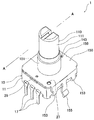
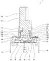
図1は本発明の第1実施形態に係る回転式電子部品1の斜視図、図2は回転式電子部品1の縦断面図(図1のA−A断面図)、図3は回転式電子部品1の分解斜視図、図4は回転式電子部品1を下側から見た分解斜視図である。これらの図に示すように回転式電子部品1は、下ケース10の収納部13内に、可動接点体50と、反転体60と、摺動子70及びシャフト110を取り付けた回転体80とを収納し、その上にクリック板140を取り付けた上ケ−ス150を取り付けて構成されている。なお以下の説明において、「上」とは回転体80からシャフト110を見る方向をいい、「下」とはその反対方向をいうものとする。
Hereinafter, embodiments of the present invention will be described in detail with reference to the drawings.
[First Embodiment]
FIG. 1 is a perspective view of a rotary
下ケース10は、上面が解放された略箱型矩形状に合成樹脂を成形してなる下ケース本体11と、下ケース本体11の収納部13の底面に露出するように設置される基板15と、下ケース本体11の対向する両側面から突出する3本と2本の端子17,19とを具備して構成されている。
The
基板15は合成樹脂フイルムの上面に所望のパターンを形成して構成されるフレキシブル回路基板であり、その上面中央には円形の第1スイッチパターン21と第1スイッチパターン21の周囲を囲む第2スイッチパターン23とからなる押圧式スイッチ用のスイッチパターンが形成され、また第2スイッチパターン23の周囲を囲む位置にはリング状で櫛歯状の回転式スイッチ用(コードスイッチ用)の第3スイッチパターン25が形成されている。また基板15の前記端子17,19を当接する部分には図示しない端子当接パターンが設けられている。
The
下ケース本体11はその上面中央に略矩形状の収納部13を有している。下ケース本体11の外周壁上面の対向する一対の角部には、上方向に向かって突出する小突起からなる係止突部27が設けられている。また下ケース本体11の外周壁上面の対向する一対の辺の中央には、それぞれ係止凹部29が設けられている。収納部13の底面には前述のように基板15の上面が露出しているが、基板15に設けた図示しない小孔を通して、基板15の上面側に、第2スイッチパターン23の周囲を囲むようにリング形状のスイッチ収納用突部31が設けられている。
The
端子17,19は、略平板状の金属板の一端を下ケース本体11の内部において基板15に設けた前記図示しない端子当接パターンに当接して固定し、他端をケース本体11の外周壁から外方に突出して下方に折り曲げて設置されている。
The
可動接点体50は弾性金属板製(例えばリン青銅板やステンレス板)であり、リング状の当接部51と、当接部51の中央に設置される可動接点部53と、当接部51の内周辺と可動接点部53の外周辺とを連結するアーム状の連結部55とを具備している。連結部55は当接部51に連結されている部分を折り曲げることで上向きに傾斜しており、これによって可動接点部53を当接部51よりも上方に位置させている。当接部51の外形寸法は、前記下ケース10のスイッチ収納用突部31の内側にほぼぴったり収納できる寸法に形成されている。
The
反転体60は絶縁性のゴム状弾性材料を略円錐状に形成して構成されており、下面には凹部61が形成されている。反転体60の中央には略円柱状の押圧部63が設けられ、押圧部63の下面には小突起状の接点押部65が形成されている。
The
摺動子70は弾性金属板をリング状に形成して構成されており、等間隔の3か所に摺動冊子71を形成し、各摺動冊子71の根元位置に小孔からなる取付部73を設けている。
The
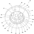
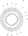
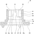
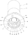
図5は回転体80を下面側から見た斜視図、図6は回転体80の裏面図、図7は回転体80をその軸部83の根元近傍部分で水平方向に切断して上側から見た図、図8は回転体80の縦断面図(図3のB−B断面図)である。なお図6に示す矢印の方向A1を回転方向(正転方向)、その反対方向を反転方向(逆転方向)ということとする。これらの図に示すように、回転体80は合成樹脂(例えばPOM樹脂等)を略円板状に形成してなる回転体本体部81の上面中央から略筒状の軸部83を突出して構成されている。軸部83の中央にはこれを貫通するシャフト軸支穴85が形成されている。
5 is a perspective view of the
シャフト軸支穴85の下部(テーパ状に広がり始める部分から下端までの部分)はシャフト軸支穴85の内径よりも大きい内径の反転体収納部87になっている。回転体80のシャフト軸支穴85の内周面の180°対向する位置には、この内周面の上下にわたって直線状に延びる(シャフト軸支穴85の上下端に解放される)横断面略矩形状の一対の上下方向ガイド溝89が形成されている。また上下方向ガイド溝89から90°回転した位置には、下端が解放され且つ上端が塞がれた状態(シャフト軸支穴85の下端には解放されるが上端には解放されない状態)の上下方向に直線状に延びる横断面略矩形状の一対の終端付上下方向ガイド溝91が形成されている。シャフト軸支穴85の下部(反転体収納部87に面している部分)の、上記各上下方向ガイド溝89から回転方向A1に向けて終端付上下方向ガイド溝91に至る部分は、係合部通過部93となっている。シャフト軸支穴85の下部の、一対の終端付上下方向ガイド溝91の前記係合部通過部93を設けた反対側には一対のストッパ部95が設けられている。ストッパ部95の下面95aの位置は係合部通過部93を設けた部分の下面93aの位置よりも下方向に向かって高くなっている。またストッパ部95の終端付上下方向ガイド溝91側の側面がストッパ面97となっている。
A lower portion of the shaft shaft support hole 85 (a portion from a portion beginning to spread in a tapered shape to a lower end) serves as a reversing
回転体80のシャフト軸支穴85の下部の前記係合部通過部93を構成する部分の内周面には、内側向きに突出する突出部からなる回転防止部100が設けられている。回転防止部100は、その内周面101が、上下方向ガイド溝89側から終端付上下方向ガイド溝91側に向かって徐々に滑らかにその突出高さを高くする形状に形成されている。これによって回転防止部100の終端付上下方向ガイド溝91に接する部分には直線状に上下方向に向かう段差部が生じる。この段差部の部分を回転防止辺103という。回転防止辺103はストッパ部95の下面95aよりも下方向にまで延びている。
On the inner peripheral surface of the portion constituting the engagement
また軸部83を構成する側壁部831の外周面の180°対向する位置には一対の凹部833が設けられ、これによって凹部833を設けた側壁部831の部分の厚みを薄くし、この部分に半径方向外方に向かう弾性を持たせている。凹部833は、図7に示すように、内側に回転防止部100を設けた側壁部831の外周面に形成されている。
In addition, a pair of
回転体本体部81のリング状の下面は摺動子取付面105となっており、この摺動子取付面105には3つの小突起からなる摺動子取付部107が設けられている。回転体本体部81のリング状の上面には多数の凹凸からなるクリック部109が設けられている。
A ring-shaped lower surface of the rotating body
図9はシャフト110の側面図である。シャフト110は合成樹脂(例えばポリカーボネート樹脂)を略円柱状に成形することで構成されており、その上部のシャフト本体部111には側面の一部が切り欠かれた操作つまみ取付部112が形成されている。シャフト110の下部にはシャフト本体部111よりもその外径寸法の小さい回転体挿入部113が設けられており、その下端部はスイッチ押圧部115となっている。回転体挿入部113の外周面の下部には、180°対向する位置から突出する略矩形状の小突起からなる一対の係合部117が設けられている。前記回転体挿入部113と係合部117は前記回転体80のシャフト軸支穴85にその上部から略ぴったり挿入できる寸法に形成されている。その際係合部117は上下方向ガイド溝89に挿入される。
FIG. 9 is a side view of the
クリック板140は弾性金属板をリング状に形成して構成されており、180°対向する位置の外周から矩形状の一対の取付部141を突出し、各取付部141内に形成した舌片状の係止片143を上方向に折り曲げて構成されている。両取付部141の間の円弧状の部分はアーム部145であり、その両端の部分を折り曲げて下方向に傾斜させ、それらの中央部分を下方向に突出する弾接部147としている。
The
上ケ−ス150は金属板を略矩形状に形成して構成されており、その中央には上方向に筒状に突出する回転体軸支部151を設け、また対向する一対の辺から下方向に向けて取付片153と、他部材取付片155とを突出して構成されている。上ケース150の外形寸法形状は、下ケース10の外形寸法形状とほぼ同じであり、下ケース10の各係止突部27に対向する位置にはこれらを挿入する小孔からなる下ケース取付部157が設けられ、前記クリック板140の各係止片143に対向する位置にはこれらを圧入する小孔からなる係止片取付部159が設けられている。
The
次に回転式電子部品1の組立方法を説明する。まず予め回転体80の摺動子取付面105に摺動子70を当接し、その際回転体80の各摺動子取付部107を摺動子70の各取付部73に挿入し、各摺動子取付部107の先端を熱カシメする。一方、上ケース150の下面にクリック板140の上面を当接することでクリック板140の一対の係止片143を上ケース150の一対の係止片取付部159に圧入して仮り止めしておく。
Next, a method for assembling the rotary
そして回転体80のシャフト軸支穴85にその上部からシャフト110の回転体挿入部113を挿入する。なお図3,図4に示すシャフト110は、シャフト110を完全に回転体80に取り付けた後の状態を示しているので、シャフト110の係合部117の方向と回転体80の上下方向ガイド溝89の方向が一致していないが、挿入の際は図3,図4に示すシャフト110又は回転体80の何れかを90°回転した状態にする。つまりシャフト110の一対の係合部117が回転体80の一対の上下方向ガイド溝89に係合しながら挿入される。図10は回転体80にシャフト110を取り付ける取付方法説明図であり、回転体80にシャフト110を完全に取り付けた後の状態を示している。但し図示の都合上、摺動子70の記載は省略している。前述のように回転体80のシャフト軸支穴85にシャフト110の回転体挿入部113を挿入すると、シャフト110の一対の係合部117が回転体80の一対の上下方向ガイド溝89に挿入されてこれを貫通し(図10に示すE地点)その全体が露出する。なおシャフト110のシャフト本体部111の下面を回転体80の軸部83の上面に当接した際(つまり回転体挿入部113を回転体80に対して最も下降させた際)、係合部117の上面は回転体80の係合部通過部93の部分の下面93aよりも下に位置し、且つストッパ部95の下面95aよりも上に位置する。従って係合部117はストッパ部95側に移動することはない。次にE地点にある係合部117を図10に示す矢印A1方向に回転して係合部通過部93を通過させて終端付上下方向ガイド溝91の真下位置(F地点)に至らせる。係合部117の移動は、係合部117がもう一つのストッパ部95に当接することで、前記F地点に確実に停止する。
Then, the rotating
なお係合部117が係合部通過部93を通過する際、係合部117の外周面が回転体80の内周面に設けた回転防止部100に当接しその表面上を摺動する。回転防止部100は係合部117が終端付上下方向ガイド溝91に向かって回転すればするほど徐々にその突出高さを高くするので、回転体80はその外径(特にその軸部83の外径)が大きくなる方向に徐々に弾性変形していく。なお上述のようにこの回転体80においては、軸部83の側壁部831の回転防止部100を設けたその外周面に凹部833を設け、これによって凹部833を設けた部分の側壁部831の厚みを薄くしたので、この側壁部831に半径方向外方に向かう弾性を持たせることができ、前記弾性変形を容易且つスムースに行わせることができる。また回転体80の材質をシャフト110の材質よりも柔らかい材質で構成しておけば(例えばシャフト110をポリカーボネート樹脂、回転体80をPOM樹脂)、さらに容易に回転体80に弾性を持たせることができる。そして係合部117全体が回転防止部100(回転防止辺103)を通過すれば、係合部117が終端付上下方向ガイド溝91の真下位置(F地点)に位置すると同時に、回転体80(特にその軸部83)の弾性変形は解除されて元の形状に戻る。つまりいわゆるスナップイン係合によって係合部117はF地点に至る。そして回転体80に対してシャフト110を上昇させれば、図10に示すように係合部117は終端付上下方向ガイド溝91内に上下動自在に挿入される。そして図10に示す状態において、回転体80に対してシャフト110を最も下降させた際、係合部117は終端付上下方向ガイド溝91の下方に露出する。つまり係合部117の上面が回転体80の係合部通過部93の下面93aよりも下に位置する。このとき係合部117の係合部通過部93側には回転防止部100が設置されているので、係合部117が係合部通過部93側に反転(矢印A1方向の逆方向に移動)することはない。
When the engaging
次に下ケース10のスイッチ収納用突部31内に可動接点体50と反転体60とを収納する。このとき可動接点体50の当接部51の下面は第2スイッチパターン23に当接する。
Next, the
そして前記クリック板140を取り付けた上ケース150の下面側に、前記摺動子70とシャフト110とを取り付けた回転体80を設置し、その際シャフト110をクリック板140の中央を通して上ケース150の回転体軸支部151に挿入する。次に前記摺動子70を取り付けた回転体80の下側に、前記可動接点体50と反転体60を取り付けた下ケース10を配置し、下ケース10の上面に上ケース150の下面を当接する。このとき下ケース10の各係止突部27を上ケース150の各下ケース取付部157に挿入して位置決めすると同時に、下ケース10の各係止凹部29にクリック板140の各取付部141を挿入して位置決めする。そして上ケース150の各取付片153を下ケース10の底面側に折り曲げれば、回転式電子部品1の組み立てが完了する。なお上記組立手順はその一例であり、他の各種異なる組立手順を用いて組み立てても良いことはいうまでもない。
Then, a rotating
以上のように回転式電子部品1は、上下ケース150,10と、上下ケース150,10内に回転自在に収納される回転体80と、下部が回転体80に設けたシャフト軸支穴85に取り付けられ上部が上ケース150上面から突出するシャフト110とを具備し、前記シャフト110下部の外周に設けた係合部117を、前記シャフト軸支穴85の内周面の上下にわたって設けた上下方向ガイド溝89にシャフト軸支穴85の上部から挿入してシャフト軸支穴85の下部に露出させて所定角度回転し、さらに前記回転体80のシャフト軸支穴85内周面に設けた終端付上下方向ガイド溝91に前記係合部117を上向きに挿入することによって、前記シャフト110を回転体80と一体に回転自在且つ回転体80内で所定ストローク上下動自在となるように取り付けて構成されている。
As described above, the rotary
そしてシャフト110を回転すれば、係合部117と終端付上下方向ガイド溝91が係合しているので、回転体80もシャフト110と共に回転し、摺動子70の摺動冊子71が基板15の第3スイッチパターン25上を摺動し、回転式スイッチのオンオフ出力が各端子17に出力される。ここで摺動子70と第3スイッチパターン25が検出手段(第1検出手段)を構成する。
When the
一方シャフト110を真下に向けて押圧すれば、反転体60の押圧部63がシャフト100のスイッチ押圧部115によって押圧されてクリック感覚を生じながら下降し、その下面の接点押部65が可動接点体50の可動接点部53を押圧してこれを下降し、可動接点部53の下面が基板15の第1スイッチパターン21に当接し、これによって第1,第2スイッチパターン21,23間を導通し、押圧式スイッチのオン状態が端子19に出力される。前記シャフト110への押圧を解除すれば、可動接点部53と反転体60の元の形状に戻ろうとする弾発力によって、それぞれが元の形状に自動復帰力し、シャフト110は元の位置まで押し上げられ、同時に前記押圧式スイッチがオフする。ここで反転体60と可動接点体50と第1,第2スイッチパターン21,23が検出手段(第2検出手段)を構成する。
On the other hand, if the
そしてこの回転式電子部品1の場合、シャフト110の上下方向へのストロークを長く構成しているので、シャフト110を最も下まで(即ちシャフト本体部111の下面が軸部83の上面に当接するまで)下降させた際、図10に示すシャフト110の係合部117は終端付上下方向ガイド溝91の下方に露出する(つまり係合部117の上面が回転体80の係合部通過部93の下面93aよりも下に位置し、且つストッパ部95の下面95aよりも上に位置する)。このとき前述のように、係合部117の係合部通過部93側には回転防止部100が設置されているので、係合部117が係合部通過部93側に反転(矢印A1方向の逆方向に移動)することはない。
In the case of the rotary
言い換えれば、シャフト110の係合部117が終端付上下方向ガイド溝91から下方に向けて露出した際に上下方向ガイド溝89側に向かって反転するのを阻止する回転防止部100を設けたので、終端付上下方向ガイド溝91の長さを長くすることなく(即ち回転式電子部品の高さ寸法を高くすることなく)、容易且つ確実にシャフト110の押圧ストロークを長くすることができる。
In other words, since the
また回転防止部100は、上下方向ガイド溝89に挿入してその下部から露出した係合部117を回転する際の係合部117の外周面に対向する回転体80の内周面に、内側向きに突出する突出部を設けることによって構成され、係合部117が回転防止部100を押圧しながら回転して乗り越えることで係合部117の上下方向ガイド溝89側への反転を阻止しているので、シャフト110と回転体80間を、従来の取付方法と同一の容易な取付方法によって結合させることができる。特に回転防止部100は、上下方向ガイド溝89側から終端付上下方向ガイド溝91側に向かって徐々にその突出高さを高くする形状なので、シャフト110の回転体80への取り付け(取り付ける際のシャフト110の回転)が容易且つスムースに行える。
Further, the
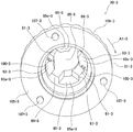
〔第2実施形態〕
図11は本発明の第2実施形態に用いる回転体80−2の裏面図である。回転体80―2以外の各部品は第1実施形態と同一なので、それらの説明は省略する。また図11に示す回転体80−2において、前記回転体80と同一部分には同一符号(但し「−2」を追記する)を付す。なお以下で説明する事項以外の事項は、前記回転体80において説明したのと同一である。
[Second Embodiment]
FIG. 11 is a back view of the rotating body 80-2 used in the second embodiment of the present invention. Since each component other than the rotating body 80-2 is the same as that of the first embodiment, the description thereof is omitted. Further, in the rotating body 80-2 shown in FIG. 11, the same parts as those of the
回転体80−2において前記回転体80と相異する点は、一対のストッパ部95を設けず、これらの部分に係合部通過部93−2及び回転防止部100−2を設けた点である。つまり回転防止部100−2は4か所に設けられている。言い換えれば上下方向ガイド溝89−2の両側からそれぞれ別の終端付上下方向ガイド溝91−2に向けて係合部通過部93−2及び回転防止部100−2を設けている。回転防止部100−2の回転防止辺103−2は何れも終端付上下方向ガイド溝91−2の両側に位置する。
The rotating body 80-2 is different from the rotating
以上のように構成した回転体80−2を用いれば、回転体80−2のシャフト軸支穴85−2に図示しないシャフト110―2を挿入して図示しない係合部117−2を上下方向ガイド溝89−2から露出させた後、何れの回転方向に向けて回転しても、スナップイン係合によってその係合部117−2を終端付上下方向ガイド溝91−2に挿入させることができる。そしてこの係合部117−2を終端付上下方向ガイド溝91−2から露出させても、終端付上下方向ガイド溝91−2の両側の回転防止部100−2(回転防止辺103−2)が係合部117−2をガイドし、係合部117―2が係合部通過部93−2側に移動することはない。これによって終端付上下方向ガイド溝91−2の長さを長くすることなく(即ち回転式電子部品1−2の高さ寸法を高くすることなく)、容易且つ確実にシャフト110−2の押圧ストロークを長くすることができる。またシャフト110−2と回転体80−2間を、従来の取付方法と同一の容易な取付方法によって結合させることができる点も、上記回転式電子部品1の場合と同様である。
When the rotating body 80-2 configured as described above is used, the shaft 110-2 (not shown) is inserted into the shaft shaft support hole 85-2 of the rotating body 80-2, and the engaging portion 117-2 (not shown) is moved in the vertical direction. After being exposed from the guide groove 89-2, the engaging portion 117-2 can be inserted into the terminal guide vertical guide groove 91-2 by snap-in engagement regardless of the rotation direction. it can. And even if this engaging part 117-2 is exposed from the vertical guide groove 91-2 with a termination | terminus, the rotation prevention part 100-2 (rotation prevention side 103-2) of the both sides of the vertical guide groove | channel 91-2 with a termination | terminus. Guides the engaging portion 117-2, and the engaging portion 117-2 does not move toward the engaging portion passing portion 93-2. Accordingly, the pressing stroke of the shaft 110-2 can be easily and reliably performed without increasing the length of the vertical guide groove 91-2 having a terminal end (that is, without increasing the height of the rotary electronic component 1-2). Can be lengthened. Further, the shaft 110-2 and the rotating body 80-2 can be coupled by the same easy mounting method as the conventional mounting method, as in the case of the rotary
〔第3実施形態〕
図12は本発明の第3実施形態に用いる回転体80−3を下面側から見た斜視図、図13は回転体80−3の縦断面図である。また図14は回転体80−3にシャフト110−3を取り付ける取付方法説明図であり、回転体80−3にシャフト110−3を完全に取り付けた後の状態を示している。但し図示の都合上、摺動子の記載は省略している。回転体80―3以外の各部品は第1実施形態と同一なので、それらの説明は省略する。またこれらの図に示す回転体80−3において、前記回転体80と同一部分には同一符号(但し「−3」を追記する)を付す。なお以下で説明する事項以外の事項は、前記回転体80において説明したのと同一である。
[Third Embodiment]
FIG. 12 is a perspective view of a rotating body 80-3 used in the third embodiment of the present invention as viewed from the lower surface side, and FIG. 13 is a longitudinal sectional view of the rotating body 80-3. FIG. 14 is an explanatory view of an attaching method for attaching the shaft 110-3 to the rotating body 80-3, and shows a state after the shaft 110-3 is completely attached to the rotating body 80-3. However, for the convenience of illustration, the description of the slider is omitted. Since each component other than the rotating body 80-3 is the same as that of the first embodiment, the description thereof is omitted. Further, in the rotating body 80-3 shown in these drawings, the same reference numerals (note that “-3” is added) are attached to the same portions as the rotating
なお図12に示す回転体80−3においては、終端付上下方向ガイド溝91−3(又は上下方向ガイド溝89−3)の両側に設けられたストッパ部95−3及び係止部通過部93−3の位置を、図5に示すストッパ部95及び係止部通過部93の位置と反対位置としている。従って上下方向ガイド溝89−3に挿入したシャフト110−3の係合部117−3を終端付上下方向ガイド溝91−3に向けて回転する回転方向A1−3は、図5の逆方向になる。
In the rotating body 80-3 shown in FIG. 12, the stopper portion 95-3 and the engaging
回転体80−3において前記回転体80と相異する点は、回転防止部100−3の位置及び形状である。すなわち回転体80の場合は係止部通過部93を構成する部分の内周面に回転防止部100を設けたが、回転体80−3の場合は係止部通過部93−3を構成する部分の下面93a−3に回転防止部100−3を設けている。回転防止部100−3は、下面93a−3から下方向に向けて突出する小突起によって構成されており、下面93a−3の終端付上下方向ガイド溝91−3側の辺の中央に設けられている。回転防止部100−3の終端付上下方向ガイド溝91−3側を向く面は、図13に示すように、終端付上下方向ガイド溝91−3の内側面と同一の面となるように、上下方向に垂直な平面状に形成されており、その反対側の面は斜面状に形成されている。
The difference between the rotating body 80-3 and the
以上のように構成された回転体80−3のシャフト軸支穴85−3にその上部からシャフト110−3の回転体挿入部113−3を挿入する。このときシャフト110−3の一対の係合部117−3が回転体80−3の一対の上下方向ガイド溝89−3に係合しながら挿入されてこれを貫通し(図14に示すE−3地点)その全体が露出する。なおシャフト110−3のシャフト本体部111−3の下面を回転体80−3の軸部83−3の上面に当接した際(つまり回転体挿入部113−3を回転体80−3に対して最も下降させた際)、係合部117−3の上面は回転体80−3の係合部通過部93−3の部分の下面93−3aよりも下に位置し、且つストッパ部95−3の下面95−3aよりも上に位置する。従って係合部117−3はストッパ部95−3側に移動することはない。次にE−3地点にある係合部117−3を図14に示す矢印A1−3方向に回転して係合部通過部93−3を通過させて終端付上下方向ガイド溝91−3の真下位置(F−3地点)に至らせる。係合部117−3の移動は、係合部117−3がもう一つのストッパ部95−3に当接することで、前記F−3地点に確実に停止する。
The rotating body insertion portion 113-3 of the shaft 110-3 is inserted into the shaft support hole 85-3 of the rotating body 80-3 configured as described above from above. At this time, the pair of engaging portions 117-3 of the shaft 110-3 are inserted while being engaged with the pair of vertical guide grooves 89-3 of the rotating body 80-3 (see E- shown in FIG. 14). 3 points) The whole is exposed. When the lower surface of the shaft main body 111-3 of the shaft 110-3 is brought into contact with the upper surface of the shaft portion 83-3 of the rotating body 80-3 (that is, the rotating body inserting portion 113-3 is connected to the rotating body 80-3 The upper surface of the engaging portion 117-3 is positioned below the lower surface 93-3a of the engaging portion passage portion 93-3 of the rotating body 80-3, and the
なお係合部117−3が係合部通過部93−3を通過する際、係合部117−3の上面が回転防止部100−3に当接しこの回転防止部100−3を押圧しながら摺動する。このとき回転防止部100−3は上方向に押圧され、同時に係合部117−3は下方向に押圧され、その後係合部117−3全体が回転防止部100−3を通過すれば、係合部117−3が終端付上下方向ガイド溝91−3の真下位置(F−3地点)に位置すると同時に、回転防止部100−3の押圧は解除される。つまりいわゆるスナップイン係合によって係合部117−3はF−3地点に至る。そして回転体80−3に対してシャフト110−3を上昇させれば、図14に示すように係合部117−3は終端付上下方向ガイド溝91−3内に上下動自在に挿入される。そして図14に示す状態において、回転体80−3に対してシャフト110−3を下降させた際、回転体80−3の係合部117−3は終端付上下方向ガイド溝91−3の下方に露出する。つまり係合部117−3の上面が回転体80−3の係合部通過部93−3の下面93−3aよりも下に位置する。このとき係合部117−3の係合部通過部93−3側には回転防止部100−3が設置されているので、係合部117−3が係合部通過部93−3側に反転(矢印A1−3方向の逆方向)することはない。 When the engaging portion 117-3 passes through the engaging portion passing portion 93-3, the upper surface of the engaging portion 117-3 abuts against the rotation preventing portion 100-3 and presses the rotation preventing portion 100-3. Slide. At this time, if the rotation preventing part 100-3 is pressed upward, and simultaneously the engaging part 117-3 is pressed downward, and then the entire engaging part 117-3 passes through the rotation preventing part 100-3, At the same time that the joint portion 117-3 is positioned at a position directly below the vertical guide groove 91-3 with a terminal end (point F-3), the pressing of the rotation preventing portion 100-3 is released. That is, the engagement portion 117-3 reaches the point F-3 by so-called snap-in engagement. When the shaft 110-3 is raised with respect to the rotating body 80-3, the engaging portion 117-3 is inserted into the vertical guide groove 91-3 with a terminal so as to move up and down as shown in FIG. . Then, in the state shown in FIG. 14, when the shaft 110-3 is lowered with respect to the rotating body 80-3, the engaging portion 117-3 of the rotating body 80-3 is below the vertical guide groove 91-3 with a terminal. Exposed to. That is, the upper surface of the engaging portion 117-3 is positioned below the lower surface 93-3a of the engaging portion passage portion 93-3 of the rotating body 80-3. At this time, since the rotation preventing part 100-3 is installed on the engaging part passing part 93-3 side of the engaging part 117-3, the engaging part 117-3 is on the engaging part passing part 93-3 side. There is no inversion (reverse direction of arrow A1-3).
なおこの回転体80−3においては、上述のように、終端付上下方向ガイド溝91−3(又は上下方向ガイド溝89−3)の両側に設けたストッパ部95−3及び係止部通過部93−3の位置を、図5に示すストッパ部95及び係止部通過部93の位置と反対位置としたが、同一位置に変更しても良い。このように構成すれば、上下方向ガイド溝89−3に挿入したシャフト110−3の係合部117−3を終端付上下方向ガイド溝91−3に向けて回転する回転方向は、図5と同一方向になる。
In the rotating body 80-3, as described above, the stopper portion 95-3 and the engaging portion passage portion provided on both sides of the vertical guide groove 91-3 with a terminal end (or the vertical guide groove 89-3). Although the position of 93-3 is opposite to the positions of the
以上本発明の実施形態を説明したが、本発明は上記実施形態に限定されるものではなく、特許請求の範囲、及び明細書と図面に記載された技術的思想の範囲内において種々の変形が可能である。なお直接明細書及び図面に記載がない何れの形状や構造や材質であっても、本願発明の作用・効果を奏する以上、本願発明の技術的思想の範囲内である。例えば、上記実施形態では一対の係合部に対応して一対の回転防止部を設けたが、一方の係合部のみに対応する1つの回転防止部のみを設けても良い(即ちもう一方の係合部に対しては回転防止部を設けない)。また係合部を一対ではなく、1つのみ設けても良く、その場合も回転防止部は1つ設置することになる。また必要に応じて、係合部や回転防止部を3か所以上に設けても良い。また回転防止部の形状・構造に種々の変形が可能であることは言うまでもなく、要はシャフトの係合部が終端付上下方向ガイド溝から下方に向けて露出した際に上下方向ガイド溝側に向かって反転するのを阻止することができる形状・構造であればどのような形状・構造であっても良い。例えば上記回転防止部100は、その内周面が上下方向ガイド溝89側から終端付上下方向ガイド溝91側に向かって徐々に滑らかにその突出高さを高くする形状に形成されているが、徐々に階段状にその突出高さを高くする形状に形成しても良い。また上記実施形態では、シャフトの係合部が上下方向ガイド溝から終端付上下方向ガイド溝まで回転するシャフトの回転体に対する回転角度を90°としているが、上下方向ガイド溝と終端付上下方向ガイド溝の回転方向に向かう相対位置を変更することで、この回転角度を90°以外の任意の角度にすることもできる。
Although the embodiments of the present invention have been described above, the present invention is not limited to the above-described embodiments, and various modifications can be made within the scope of the technical idea described in the claims and the specification and drawings. Is possible. Note that any shape, structure, or material not directly described in the specification and drawings is within the scope of the technical idea of the present invention as long as the effects and advantages of the present invention are exhibited. For example, in the above embodiment, a pair of rotation preventing portions is provided corresponding to the pair of engaging portions, but only one rotation preventing portion corresponding to only one engaging portion may be provided (that is, the other one). (An anti-rotation part is not provided for the engaging part). Moreover, you may provide only one engaging part instead of a pair, and the rotation prevention part will be installed also in that case. Moreover, you may provide an engaging part and a rotation prevention part in three or more places as needed. Needless to say, the shape and structure of the anti-rotation part can be modified in various ways. In short, when the engaging part of the shaft is exposed downward from the vertical guide groove with a terminal end, it moves to the vertical guide groove side. Any shape / structure may be used as long as the shape / structure can be prevented from being reversed. For example, the
また上記回転式電子部品1では、摺動子70と第3スイッチパターン25によって第1検出手段を構成し、反転体60と可動接点体50と第1,第2スイッチパターン21,23によって第2検出手段を構成したが、何れも他の各種構造のスイッチであっても良い。また検出手段はスイッチに限らず、可変抵抗器等の他の各種検出手段でも良い。要は検出手段は、回転体又はシャフトを操作することで所望の電気的出力、磁気的出力、光学的出力等の各種出力が得られるのもであればよい。
In the rotary
1 回転式電子部品
10 下ケース(ケース)
15 基板
17,19 端子
21 第1スイッチパターン(第2検出手段、検出手段)
23 第2スイッチパターン(第2検出手段、検出手段)
25 第3スイッチパターン(第1検出手段、検出手段)
50 可動接点体(第2検出手段、検出手段)
60 反転体(第2検出手段、検出手段)
70 摺動子(第1検出手段、検出手段)
80 回転体
81 回転体本体部
83 軸部
831 側壁部
833 凹部
85 シャフト軸支穴
87 反転体収納部
89 上下方向ガイド溝
91 終端付上下方向ガイド溝
93 係合部通過部
95 ストッパ部
100 回転防止部
101 内周面
110 シャフト
111 シャフト本体部
113 回転体挿入部
115 スイッチ押圧部
117 係合部
140 クリック板
150 上ケ−ス(ケース)
80−2 回転体
80−3 回転体
100−3 回転防止部
1 Rotating
15
23 Second switch pattern (second detection means, detection means)
25 3rd switch pattern (1st detection means, detection means)
50 Movable contact body (second detection means, detection means)
60 Inversion body (second detection means, detection means)
70 Slider (first detection means, detection means)
DESCRIPTION OF
80-2 Rotating body 80-3 Rotating body 100-3 Anti-rotation part
Claims (4)
前記シャフト下部の外周に設けた係合部を、前記回転体のシャフト軸支穴内周面の上下にわたって設けた上下方向ガイド溝にシャフト軸支穴の上部から挿入してシャフト軸支穴の下部に露出させて所定角度回転し、さらに前記回転体のシャフト軸支穴内周面に設けた終端付上下方向ガイド溝に前記係合部を上向きに挿入することによって、前記シャフトを回転体と一体に回転自在且つ回転体内で所定ストローク上下動自在となるように取り付けてなる回転式電子部品において、
前記回転体には、前記シャフトの係合部が前記終端付上下方向ガイド溝から下方に向けて露出した際に前記上下方向ガイド溝側に向かって反転するのを阻止する回転防止部が設けられていることを特徴とする回転式電子部品。 A case, a rotating body that is rotatably accommodated in the case, and a shaft whose lower part is attached to a shaft shaft support hole provided in the rotating body and whose upper part protrudes from the upper surface of the case,
The engaging portion provided on the outer periphery of the lower portion of the shaft is inserted from the upper portion of the shaft shaft supporting hole into the vertical guide groove provided on the upper and lower sides of the inner surface of the shaft shaft supporting hole of the rotating body. The shaft is rotated integrally with the rotating body by being exposed and rotated by a predetermined angle, and by further inserting the engaging portion upward into a vertical guide groove with a terminal provided on the inner peripheral surface of the shaft shaft support hole of the rotating body. In a rotary electronic component that is freely and can be moved up and down by a predetermined stroke within a rotating body,
The rotating body is provided with a rotation preventing portion that prevents the shaft engaging portion from being reversed toward the vertical guide groove when the engaging portion of the shaft is exposed downward from the terminal vertical guide groove. Rotating electronic parts characterized by
前記回転防止部は、前記上下方向ガイド溝に挿入してその下部から露出した前記係合部を回転する際の係合部の外周面に対向する回転体の内周面に、内側向きに突出する突出部を設けることによって構成され、前記係合部が前記回転防止部を押圧しながら回転して乗り越えることで前記係合部の前記上下方向ガイド溝側への反転を阻止することを特徴とする回転式電子部品。 The rotary electronic component according to claim 1,
The rotation preventing portion protrudes inwardly on the inner peripheral surface of the rotating body that opposes the outer peripheral surface of the engaging portion when the engaging portion that is inserted into the vertical guide groove and exposed from the lower portion is rotated. The protrusion is configured to provide a protruding portion, and the engagement portion rotates and gets over while pressing the rotation prevention portion, thereby preventing the engagement portion from reversing to the vertical guide groove side. Rotating electronic components.
内側に前記回転防止部を設けた前記回転体の側壁部に、半径方向外方に向かう弾性を持たせたことを特徴とする回転式電子部品。 The rotary electronic component according to claim 2,
A rotary electronic component characterized in that a side wall portion of the rotating body provided with the rotation preventing portion on the inner side is provided with elasticity toward a radially outward direction.
前記回転防止部は、前記上下方向ガイド溝側から前記終端付上下方向ガイド溝側に向かって徐々にその突出高さを高くする形状に形成されていることを特徴とする回転式電子部品。 The rotary electronic component according to claim 3,
The rotary electronic component according to claim 1, wherein the rotation preventing portion is formed in a shape that gradually increases its protruding height from the vertical guide groove side toward the terminally-attached vertical guide groove side.
Priority Applications (1)
| Application Number | Priority Date | Filing Date | Title |
|---|---|---|---|
| JP2011113635A JP5735348B2 (en) | 2011-05-20 | 2011-05-20 | Rotating electronic components |
Applications Claiming Priority (1)
| Application Number | Priority Date | Filing Date | Title |
|---|---|---|---|
| JP2011113635A JP5735348B2 (en) | 2011-05-20 | 2011-05-20 | Rotating electronic components |
Publications (2)
| Publication Number | Publication Date |
|---|---|
| JP2012243631A true JP2012243631A (en) | 2012-12-10 |
| JP5735348B2 JP5735348B2 (en) | 2015-06-17 |
Family
ID=47465102
Family Applications (1)
| Application Number | Title | Priority Date | Filing Date |
|---|---|---|---|
| JP2011113635A Expired - Fee Related JP5735348B2 (en) | 2011-05-20 | 2011-05-20 | Rotating electronic components |
Country Status (1)
| Country | Link |
|---|---|
| JP (1) | JP5735348B2 (en) |
Families Citing this family (1)
| Publication number | Priority date | Publication date | Assignee | Title |
|---|---|---|---|---|
| CN111261441B (en) * | 2020-01-19 | 2021-11-30 | 邳州市鑫盛创业投资有限公司 | Prevent gaseous fire extinguishing systems of track traffic of mistake jet-propelled promptly to start and stop button |
Citations (3)
| Publication number | Priority date | Publication date | Assignee | Title |
|---|---|---|---|---|
| JPH10334767A (en) * | 1997-06-02 | 1998-12-18 | Alps Electric Co Ltd | Assembly structure of rotary operation type electric component |
| JP2007201415A (en) * | 2005-12-28 | 2007-08-09 | Alps Electric Co Ltd | Rotary type electrical component |
| US20080289439A1 (en) * | 2007-05-25 | 2008-11-27 | Matsushita Electric Industrial Co., Ltd. | Rotary clicking electronic component |
-
2011
- 2011-05-20 JP JP2011113635A patent/JP5735348B2/en not_active Expired - Fee Related
Patent Citations (3)
| Publication number | Priority date | Publication date | Assignee | Title |
|---|---|---|---|---|
| JPH10334767A (en) * | 1997-06-02 | 1998-12-18 | Alps Electric Co Ltd | Assembly structure of rotary operation type electric component |
| JP2007201415A (en) * | 2005-12-28 | 2007-08-09 | Alps Electric Co Ltd | Rotary type electrical component |
| US20080289439A1 (en) * | 2007-05-25 | 2008-11-27 | Matsushita Electric Industrial Co., Ltd. | Rotary clicking electronic component |
Also Published As
| Publication number | Publication date |
|---|---|
| JP5735348B2 (en) | 2015-06-17 |
Similar Documents
| Publication | Publication Date | Title |
|---|---|---|
| US7507919B2 (en) | Multi-directional input device | |
| EP1835569B1 (en) | Connector for flexible substrate | |
| JP4487821B2 (en) | Composite operation type electronic parts | |
| JP2001084877A (en) | Pressing and rotating electronic parts | |
| JP2000231860A (en) | Pressing and rotating electronic parts | |
| JPH1139998A (en) | Rotary encoder | |
| JP5735348B2 (en) | Rotating electronic components | |
| JP5802078B2 (en) | Push switch | |
| JP2009152117A (en) | Rotating electronic components | |
| JP4405795B2 (en) | Control device with multiple axial positions for electronic equipment | |
| JP5463245B2 (en) | Rotating electronic components | |
| KR100423776B1 (en) | Switch device | |
| JP3723714B2 (en) | Rotating electrical parts | |
| KR20180112143A (en) | Push switching unit | |
| JP2009146649A (en) | Electronic parts with click function | |
| JP7187066B2 (en) | Sliders for rotary electronic parts | |
| JP4136625B2 (en) | Rotating electronic components | |
| JP5180725B2 (en) | Rotary slider assembly and rotary electronic component | |
| JP6643137B2 (en) | Rotary electronic components with click mechanism | |
| JPH10334766A (en) | Rotary electric component | |
| JP2010277711A (en) | Click mechanism and rotating electronic parts | |
| JP6549979B2 (en) | Rotary electronic parts with pressure switch | |
| JP2007207563A (en) | Electric device operation mechanism | |
| JP4619196B2 (en) | Sliding electronic parts with pressure switch | |
| JP2009283311A (en) | Inputting device and electronic equipment having this inputting device |
Legal Events
| Date | Code | Title | Description |
|---|---|---|---|
| A621 | Written request for application examination |
Free format text: JAPANESE INTERMEDIATE CODE: A621 Effective date: 20140227 |
|
| A977 | Report on retrieval |
Free format text: JAPANESE INTERMEDIATE CODE: A971007 Effective date: 20141024 |
|
| A131 | Notification of reasons for refusal |
Free format text: JAPANESE INTERMEDIATE CODE: A131 Effective date: 20141118 |
|
| A521 | Written amendment |
Free format text: JAPANESE INTERMEDIATE CODE: A523 Effective date: 20150108 |
|
| TRDD | Decision of grant or rejection written | ||
| A01 | Written decision to grant a patent or to grant a registration (utility model) |
Free format text: JAPANESE INTERMEDIATE CODE: A01 Effective date: 20150414 |
|
| A61 | First payment of annual fees (during grant procedure) |
Free format text: JAPANESE INTERMEDIATE CODE: A61 Effective date: 20150416 |
|
| R150 | Certificate of patent or registration of utility model |
Ref document number: 5735348 Country of ref document: JP Free format text: JAPANESE INTERMEDIATE CODE: R150 |
|
| R250 | Receipt of annual fees |
Free format text: JAPANESE INTERMEDIATE CODE: R250 |
|
| R250 | Receipt of annual fees |
Free format text: JAPANESE INTERMEDIATE CODE: R250 |
|
| R250 | Receipt of annual fees |
Free format text: JAPANESE INTERMEDIATE CODE: R250 |
|
| LAPS | Cancellation because of no payment of annual fees |