JP2012246071A - Paper sheet takeout device and paper sheet processing device provided with the same - Google Patents

Paper sheet takeout device and paper sheet processing device provided with the same Download PDF

Info

Publication number
JP2012246071A
JP2012246071A JP2011117033A JP2011117033A JP2012246071A JP 2012246071 A JP2012246071 A JP 2012246071A JP 2011117033 A JP2011117033 A JP 2011117033A JP 2011117033 A JP2011117033 A JP 2011117033A JP 2012246071 A JP2012246071 A JP 2012246071A
Authority
JP
Japan
Prior art keywords
take
paper sheet
paper
postal matter
suction
Prior art date
Legal status (The legal status is an assumption and is not a legal conclusion. Google has not performed a legal analysis and makes no representation as to the accuracy of the status listed.)
Withdrawn
Application number
JP2011117033A
Other languages
Japanese (ja)
Inventor
Tetsuo Watanabe
哲雄 渡辺
Current Assignee (The listed assignees may be inaccurate. Google has not performed a legal analysis and makes no representation or warranty as to the accuracy of the list.)
Toshiba Corp
Original Assignee
Toshiba Corp
Priority date (The priority date is an assumption and is not a legal conclusion. Google has not performed a legal analysis and makes no representation as to the accuracy of the date listed.)
Filing date
Publication date
Application filed by Toshiba Corp filed Critical Toshiba Corp
Priority to JP2011117033A priority Critical patent/JP2012246071A/en
Publication of JP2012246071A publication Critical patent/JP2012246071A/en
Withdrawn legal-status Critical Current

Links

Images

Landscapes

  • Controlling Sheets Or Webs (AREA)
  • Sheets, Magazines, And Separation Thereof (AREA)

Abstract

【課題】紙葉類の多重取りを抑制し、紙葉類を安定して取出すことのできる紙葉類の取出し装置および紙葉類処理装置を提供する。
【解決手段】実施形態によれば、紙葉類の取出し装置は、複数枚重ねて載置された紙葉類をその重ね方向に移動させて移動方向先端にある紙葉類を取出し位置へ供給する供給機構2と、取出し位置に供給された紙葉類を前記投入部から1枚ずつ取出す取出し機構56と、紙葉類の形態を検出する検出器122と、を備えている。取出し機構は、取出し位置にある紙葉類を取出す取出し部材79と、取出し部材を通して吸気し前記紙葉類を取出し部材に吸着する空気吸引源61と、取出し部材と空気吸引源との間に設けられ吸着力を調整するバルブ装置300と、検出器により検出された紙葉類の形態に応じて、吸着時の吸着力を前記バルブ装置により変更する制御部と、を備えている。
【選択図】図2
The present invention provides a paper sheet take-out device and a paper sheet processing device capable of suppressing multiple take-up of paper sheets and stably taking out paper sheets.
According to an embodiment, a paper sheet take-out device moves a plurality of stacked paper sheets in the stacking direction and supplies the paper sheets at the leading end in the moving direction to a take-out position. A supply mechanism 2, a take-out mechanism 56 for taking out the paper sheets supplied to the take-out position one by one from the input section, and a detector 122 for detecting the form of the paper sheets. The take-out mechanism is provided between the take-out member 79 and the air suction source, a take-out member 79 that takes out the paper sheet at the take-out position, an air suction source 61 that sucks air through the take-out member and adsorbs the paper sheet. A valve device 300 for adjusting the suction force, and a control unit for changing the suction force at the time of suction by the valve device in accordance with the form of the paper sheet detected by the detector.
[Selection] Figure 2

Description

この発明の実施形態は、郵便物等の集積された紙葉類を1枚ずつ取出して送り出す紙葉類の取出し装置、およびこれを備える紙葉類処理装置に関する。   FIELD Embodiments described herein relate generally to a paper sheet take-out device that picks up and feeds accumulated paper sheets such as postal items one by one, and a paper sheet processing apparatus including the same.

ハガキ、封書などの郵便物を扱う郵便物処理機などの紙葉類処理装置は、例えば、取出し装置、判別装置(OCR)、集積装置、リジェクト(RJ)集積装置、スイッチバック装置、各装置間を結ぶ搬送路、搬送されてきた紙葉類(郵便物)を各装置に振り分けるゲート等を備えている。取出し装置の供給部にセットした複数枚の紙葉類は、取出し装置にて1枚1枚に分離して取出され、判別装置に送られる。判別装置は、紙葉類の判別し、紙葉類の行き先、例えば、RJ集積装置あるいは集積装置を決定する。その後、紙葉類は、搬送路、ゲート機構を通じて、決定された装置へ搬送され、この装置内で各種処理が行われる。   Paper processing devices such as postal processing machines that handle postal items such as postcards and sealed letters, for example, take-out devices, discriminating devices (OCR), stacking devices, reject (RJ) stacking devices, switchback devices, and between each device And a gate that sorts the conveyed paper sheets (mail) to each device. The plurality of paper sheets set in the supply unit of the take-out device are taken out one by one by the take-out device and sent to the determination device. The discriminating device discriminates the paper sheet and determines the destination of the paper sheet, for example, the RJ stacking device or the stacking device. Thereafter, the paper sheet is conveyed to the determined apparatus through the conveyance path and the gate mechanism, and various processes are performed in this apparatus.

紙葉類処理装置の取出し装置としては、負圧により紙葉類を吸着して取出す吸着取出し方式の取出し装置が提供されている。この取出し装置は、穴開きベルト、エアーチャンバ、バルブ装置を用いて紙葉類を吸着するエアー吸着構造を有し、バルブ装置により1枚ごとに吸着をON−OFFすることにより、供給部で送られてきた紙葉類を1枚ずつ取出すことを可能にする。   As a take-out device of the paper sheet processing apparatus, an adsorption take-out type take-out apparatus that picks up and takes out paper sheets by a negative pressure is provided. This take-out device has an air adsorbing structure that adsorbs paper sheets using a perforated belt, an air chamber, and a valve device. It makes it possible to take out the paper sheets that have been taken one by one.

特開2009−258182号公報JP 2009-258182 A 特開2008−280139号公報JP 2008-280139 A

上記のようなエアー吸着構造を用いた紙葉類の取出し装置では、通常の書状を取出す場合に比較して、例えば、薄くて透気しやすい書状を取出す場合においては、取出すべき書状の次の2枚目の書状までエアー吸着影響が及び易く、多重取出しの可能性が高まってしまう。すなわち、本来、取出すべき1枚目の書状だけでなく、次の2枚目の書状までエアー吸着影響が及ぶ可能性があり、1枚目が取出されるのと同時に2枚目も付いていく等、多重取出しの可能性が高まってしまう。   In the paper sheet take-out device using the air adsorption structure as described above, for example, when taking out a thin and airy letter, the next to the letter to be taken out is compared with taking out a normal letter. Air adsorption is easily affected up to the second letter, increasing the possibility of multiple takeout. In other words, there is a possibility that not only the first letter to be taken out but also the next second letter may have an air adsorption effect, and the second one is attached at the same time as the first one is taken out. Etc., and the possibility of multiple extraction increases.

また、通常の書状よりも小さい書状、つまり、取出し方向に対して短い書状、を取出す場合、エアー吸着機構のエアーが切れる前に1枚目の書状が前に抜けていくため、次の書状へのエアー吸着影響が及ぶ。すなわち、通常の長さの書状であれば、取出された前の書状が所定の位置まで到達し、エアー吸着が切れた後に、2枚目の書状が吸着位置に面するようになるので問題ない。しかし、短い書状の場合、所定の位置に到達した時点で、次に来る2枚目の書状がエアー吸着され前に送り出されている可能性がある。つまり、多重取出しの可能性が高まる。   In addition, when taking out letters that are smaller than normal letters, that is, letters that are shorter than the take-out direction, the first letter will be removed before the air of the air suction mechanism is cut off. The air adsorption effect of. That is, if the letter has a normal length, there is no problem because the second letter comes to face the suction position after the previous letter that has been taken out reaches a predetermined position and the air suction stops. . However, in the case of a short letter, when the predetermined position is reached, the next second letter may be adsorbed by air and sent out before. That is, the possibility of multiple extraction increases.

この発明は以上の点に鑑みなされたもので、その課題は、多重取り出しを低減し、安定した紙葉類の取出しが可能な紙葉類の取り出し装置およびこれを備える紙葉類処理装置を提供することにある。   The present invention has been made in view of the above points, and an object of the present invention is to provide a paper sheet take-out apparatus capable of reducing multiple take-out and stably taking out paper sheets, and a paper sheet processing apparatus including the same. There is to do.

実施形態によれば、紙葉類の取出し装置は、複数枚重ねて載置された紙葉類をその重ね方向に移動させて移動方向先端にある紙葉類を取出し位置へ供給する供給機構と、前記取出し位置に供給された紙葉類を前記投入部から1枚ずつ取出す取出し機構と、前記紙葉類の形態を検出する検出器と、を備え、
前記取出し機構は、前記取出し位置にある紙葉類を取出す取出し部材と、前記取出し部材を通して吸気し前記紙葉類を取出し部材に吸着する空気吸引源と、前記取出し部材と空気吸引源との間に設けられ吸着力を調整するバルブ装置と、前記検出器により検出された紙葉類の形態に応じて、吸着時の吸着力を前記バルブ装置により変更する制御部と、を備えている。
According to the embodiment, the paper sheet take-out device includes a supply mechanism that moves a plurality of stacked paper sheets in the stacking direction and supplies the paper sheets at the leading end in the moving direction to the take-out position. A take-out mechanism for taking out the paper sheets supplied to the take-out position one by one from the input unit, and a detector for detecting the form of the paper sheets,
The take-out mechanism includes a take-out member that takes out the paper sheet at the take-out position, an air suction source that sucks air through the take-out member and adsorbs the paper sheet to the take-out member, and a space between the take-out member and the air suction source. And a control unit that changes the suction force at the time of suction using the valve device according to the form of the paper sheet detected by the detector.

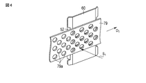
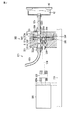
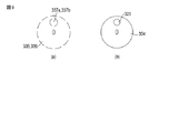
図1は、実施形態に係る郵便物処理装置を概略的に示すブロック図。FIG. 1 is a block diagram schematically illustrating a mail processing apparatus according to an embodiment. 図2は、前記郵便物処理装置の取出し装置を示す平面図。FIG. 2 is a plan view showing a take-out device of the mail processing apparatus. 図3は、前記取出し装置の投入部を示す斜視図FIG. 3 is a perspective view showing a loading portion of the take-out device. 図4は、前記取出し装置の取出しベルトおよびガイドを示す斜視図。FIG. 4 is a perspective view showing a take-out belt and a guide of the take-out device. 図5は、前記ガイドを示す斜視図。FIG. 5 is a perspective view showing the guide. 図6は、前記取出し装置のバルブ装置を示す側面図。FIG. 6 is a side view showing a valve device of the take-out device. 図7は、前記バルブ装置を拡大して示す断面図。FIG. 7 is an enlarged cross-sectional view of the valve device. 図8は、前記バルブ装置の正面図。FIG. 8 is a front view of the valve device. 図9は、前記バルブ装置の対向板および遮蔽板を示す正面図。FIG. 9 is a front view showing a counter plate and a shielding plate of the valve device. 図10は、前記バルブ装置において、通常モードでの吸気オンおよび吸気オフにおける対向板および遮蔽板を示す正面図。FIG. 10 is a front view showing an opposing plate and a shielding plate in intake mode on and off mode in the normal mode in the valve device. 図11は、前記バルブ装置において、吸着力低減モードでの吸気オンおよび吸気オフにおける対向板および遮蔽板を示す正面図。FIG. 11 is a front view showing a counter plate and a shielding plate in intake on and off in the suction force reduction mode in the valve device. 図12は、前記取出し装置の吸引機構を示す斜視図。FIG. 12 is a perspective view showing a suction mechanism of the take-out device. 図13は、前記取出し装置の制御部および各種センサを示すブロック図。FIG. 13 is a block diagram illustrating a control unit and various sensors of the take-out device. 図14は、単位時間あたりの郵便物の厚さの積分値の変化を示す図。FIG. 14 is a diagram showing a change in the integrated value of the thickness of the mail piece per unit time. 図15は、前記取出し装置の供給部に装填されたバルク状態の郵便物の例を示す平面図。FIG. 15 is a plan view showing an example of a mail piece in a bulk state loaded in the supply unit of the take-out apparatus. 図16は、吸気機構のバルブ装置の制御動作を示すフローチャート。FIG. 16 is a flowchart showing a control operation of the valve device of the intake mechanism. 図17は、通常モードの吸気オン時における吸着機構のエアー吸着圧力の変化および遮蔽板の位相角度を示す図。FIG. 17 is a diagram illustrating a change in air suction pressure of the suction mechanism and a phase angle of the shielding plate when the intake air is on in the normal mode. 図18は、他の実施形態に係る取出し装置において、吸着力低減モードでのバルブ装置の吸気オン動作を概略的に示す図。FIG. 18 is a diagram schematically showing an intake-on operation of the valve device in the adsorption force reduction mode in the take-out device according to another embodiment. 図19は、他の実施形態に係る取出し装置において、吸着力低減モードの吸気オン時における吸着機構のエアー吸着圧力の変化および遮蔽板の位相角度を示す図。FIG. 19 is a diagram showing a change in the air adsorption pressure of the adsorption mechanism and the phase angle of the shielding plate when the intake air is on in the adsorption force reduction mode in the take-out device according to another embodiment.

以下、図面を参照しながら本発明の実施形態について、詳細に説明する。
図1は、実施形態に係る紙葉類の取出し装置1を含む紙葉類処理装置100を概略的に示すブロック図である。この紙葉類処理装置100は、取出し装置1の他に、判別部102、リジェクト部104、スイッチバック部106、および集積部108を備えている。なお、本実施形態の処理装置100で処理する紙葉類は郵便物であるが、被処理媒体(すなわち紙葉類)は郵便物に限るものではない。
Hereinafter, embodiments of the present invention will be described in detail with reference to the drawings.
FIG. 1 is a block diagram schematically showing a paper sheet processing apparatus 100 including a paper sheet take-out apparatus 1 according to the embodiment. In addition to the take-out device 1, the paper sheet processing apparatus 100 includes a determination unit 102, a rejection unit 104, a switchback unit 106, and a stacking unit 108. In addition, although the paper sheets processed with the processing apparatus 100 of this embodiment are mails, the to-be-processed medium (namely, paper sheets) is not restricted to mails.

ハガキ、封書などの郵便物は、複数枚積層された状態で取出し装置1にセットされ、取出し装置を後述するように動作することで、搬送路101上に1枚ずつ取出される。搬送路101には、図示しない複数組の無端状の搬送ベルトが搬送路101を挟むように延設されている。取出された郵便物は、搬送ベルトに挟持されて搬送される。   A plurality of postal items such as postcards and sealed letters are set in the take-out device 1 in a stacked state, and are taken out one by one on the conveyance path 101 by operating the take-out device as described later. In the conveyance path 101, a plurality of endless conveyance belts (not shown) are extended so as to sandwich the conveyance path 101. The picked-up postal matter is sandwiched and transported by a transport belt.

搬送路101上に取出された郵便物は、判別部102に送られ、ここで郵便物から各種情報が読み取られる。判別部102は、読み取った各種情報に基づいて、郵便物の搬送姿勢や区分先などを判別する。特に、判別部102は、郵便物に書かれてある郵便番号や住所などの宛先情報を読み取って区分先を判別する。   The postal matter taken out on the conveyance path 101 is sent to the determination unit 102 where various information is read from the postal matter. The discriminating unit 102 discriminates a postal item transport posture, a sorting destination, and the like based on the read various information. In particular, the determination unit 102 reads destination information such as a postal code and an address written on a postal matter, and determines a sorting destination.

判別部102を通過した後、郵便物は、ゲートG1を介してその搬送方向が振り分けられる。つまり、判別部102でリジェクトすべき郵便物であることが判別された郵便物は、ゲートG1を介してリジェクト部104へ搬送され、リジェクト部に集積される。それ以外の郵便物は、ゲートG1を介して集積部108へ搬送され、この集積部108内に集積される。   After passing through the determination unit 102, the postal matter is sorted in the transport direction via the gate G1. That is, the postal matter that has been determined to be rejected by the determining unit 102 is conveyed to the rejecting unit 104 via the gate G1 and accumulated in the rejecting unit. Other mail items are transported to the stacking unit 108 via the gate G1 and stacked in the stacking unit 108.

このとき、郵便物の搬送方向を逆転させる必要があることを判別部102で判別した場合、郵便物はゲートG1およびゲートG2を介してスイッチバック部106へ送り込まれ、ここで搬送方向が逆転される。搬送方向を逆転する必要のない郵便物は、ゲートG2を介してスイッチバック部106を迂回され、集積部108へ搬送される。   At this time, when the determination unit 102 determines that the transport direction of the postal matter needs to be reversed, the postal matter is sent to the switchback unit 106 via the gate G1 and the gate G2, and the transport direction is reversed here. The Mails that do not need to reverse the transport direction are bypassed the switchback unit 106 via the gate G2 and transported to the stacking unit 108.

搬送路101を介して集積部108へ送り込まれた郵便物は、判別部102における判別結果に従って図示しない区分集積ポケットに区分集積される。各区分集積ポケットに区分集積される郵便物は、天地が揃った状態で集積される。   Mails sent to the stacking unit 108 via the transport path 101 are sorted and collected in a sorting / stacking pocket (not shown) according to the determination result in the determination unit 102. Mail pieces that are classified and accumulated in the respective division accumulation pockets are collected with the top and bottom aligned.

次に、紙葉類の取出し装置1について詳細に説明する。
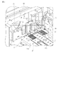
図2は、取出し装置1を示す平面図である。取出し装置1は、複数通の郵便物Pを積層状態で、かつ、各郵便物が水平面に対してほぼ垂直に立った立位状態でセットされる投入部(供給部)51、投入された複数通の郵便物Pをその重ね方向に移動させて移動方向先端にある郵便物Pを後述する取出し位置87へ供給する供給機構2、取出し位置87に供給された郵便物Pをその面方向、ここでは、移動方向とほぼ直交する方向、に送って後述する搬送路10上に取出す取出し機構56、投入部51を介して投入された郵便物Pのうち最先の郵便物Pを取出し位置87に向けて吸引する吸引機構53、取出し位置87から取出される郵便物Pに連れ出される2通目以降の郵便物Pを1通目の郵便物Pから分離する分離機構54、取出し位置87に供給された郵便物Pに対して取出し機構56よりも上流側で負圧を作用させて正逆両方向に回転することで当該郵便物Pの取出し動作を補助する補助機構55、および分離機構54を通過した郵便物Pを取出し速度よりも少し速い速度で引き抜いて下流側へ搬送する搬送機構58を備えている。
Next, the paper sheet take-out device 1 will be described in detail.
FIG. 2 is a plan view showing the take-out device 1. The take-out device 1 is composed of an input unit (supply unit) 51 in which a plurality of mail items P are stacked and set in a standing state in which each mail item stands substantially perpendicular to a horizontal plane. The postal matter P is moved in the stacking direction to supply the postal matter P at the leading end in the moving direction to an unloading position 87, which will be described later, and the postal matter P supplied to the unloading position 87 in the surface direction, here Then, the first postal matter P out of the postal matter P sent through the take-out mechanism 56 and the throwing-in part 51, which is sent in a direction substantially orthogonal to the moving direction and taken out on the transport path 10 to be described later, is taken out to the take-out position 87. Suction mechanism 53 for sucking toward the post, and postal mail P taken out from the postal matter P taken out from the takeout position 87 is supplied to the separation mechanism 54 for separating the postal matter P from the first postal matter P, and the takeout position 87. Pick-up mechanism for postal mail P The auxiliary mechanism 55 for assisting the operation of taking out the postal matter P by applying a negative pressure on the upstream side of 6 and rotating in both the forward and reverse directions, and the postage P that has passed through the separation mechanism 54 is slightly faster than the take-out speed. A transport mechanism 58 that pulls out at a high speed and transports it downstream is provided.

取出し装置1は、投入部51の一端にある取出し位置87から搬送路10上に取出された郵便物Pの通過を検知する2つのセンサ57a、57b、および複数の搬送ガイド84を有する。2つのセンサ57a、57bは、それぞれ、郵便物Pが通過する搬送路10を挟むように配設された発光部および受光部を有し、その光軸を郵便物Pが遮ることをもって当該郵便物Pの通過を順に検知する。また、複数の搬送ガイド84は、郵便物Pの端辺や面を接触させてその移動や搬送をガイドする。   The take-out device 1 includes two sensors 57 a and 57 b that detect the passage of the postal matter P taken out from the take-out position 87 at one end of the input unit 51 onto the carry path 10, and a plurality of carry guides 84. Each of the two sensors 57a and 57b has a light emitting unit and a light receiving unit disposed so as to sandwich the conveyance path 10 through which the postal matter P passes, and the postal matter P blocks the optical axis so that the postal matter The passage of P is detected in order. In addition, the plurality of transport guides 84 guide the movement and transport of the postal matter P by contacting the edges and surfaces thereof.

図2および図3に示すように、投入部51には、複数枚の郵便物Pが重ねられた状態で且つ立位状態でまとめて載置される。投入部51の底壁51aには、各郵便物Pの下端辺を当接せしめてその重ね方向(図中矢印F方向)に送るメインベルト126と、郵便物Pの姿勢(傾き)を調整する一対のサブベルト125と、が設けられ、各々独立して駆動可能となっている。メインベルト126は、送り方向Fに沿って、投入部51のほぼ全長に亘って延びている。サブベルト125は、取出し位置87の近傍で、メインベルト126の両側に設けられている。   As shown in FIGS. 2 and 3, a plurality of pieces of mail P are stacked and placed together in a standing position on the input unit 51. The main belt 126 which is brought into contact with the bottom wall 51a of the insertion portion 51 and the lower end side of each postal matter P in the overlapping direction (the direction of arrow F in the figure) and the posture (tilt) of the postal matter P are adjusted. A pair of sub-belts 125 are provided and can be driven independently. The main belt 126 extends along the feed direction F over almost the entire length of the input portion 51. The sub belt 125 is provided on both sides of the main belt 126 in the vicinity of the take-out position 87.

複数枚の郵便物Pのうち移動方向後端にある郵便物Pに面接する位置にはバックアッププレート9が配置されている。バックアッププレート9は、例えば、メインベルト126に簡易的に接続され、メインベルト126と同期して矢印F方向に移動することで郵便物Pを取出し位置方向に押し、移動方向先端の郵便物Pを取出し位置87へ供給する。これらメインベルト126、サブベルト125、バックアッププレート9、およびメインベルト、サブベルトを駆動する後述の駆動モータ90は、供給機構2として機能する。   A backup plate 9 is arranged at a position where the postal matter P at the rear end in the moving direction is in contact with the postal matter P among the plurality of postal items P. For example, the backup plate 9 is simply connected to the main belt 126 and moves in the direction of the arrow F in synchronization with the main belt 126 to take out the postal matter P in the direction of the take-out position. Supply to take-out position 87. The main belt 126, the sub belt 125, the backup plate 9, and a drive motor 90 described later that drives the main belt and the sub belt function as the supply mechanism 2.

1つの搬送ガイド84は、矢印F方向に沿って投入部51の一側を規定する位置に延設され、各郵便物Pの端辺を案内する。また、他の複数の搬送ガイド84は、投入部51の一端側の取出し位置87に沿って並べて配置され、矢印F方向に供給された移動方向先端の郵便物Pを取出し位置87に停止および位置決めするよう機能するとともに、取出し位置87から取出される郵便物Pの片面に接触して案内するよう機能する。   One transport guide 84 is extended to a position that defines one side of the input unit 51 along the direction of arrow F, and guides the end sides of each postal matter P. The plurality of other transport guides 84 are arranged side by side along the take-out position 87 on one end side of the loading unit 51, and stop and position at the take-out position 87 at the front end of the moving direction P supplied in the direction of arrow F. And functions to contact and guide one side of the postal matter P taken out from the take-out position 87.

図2に示すように、取出し機構56は、チャンバ52、ガイド60、および真空ポンプ61(または相当品)を有する。真空ポンプ61は配管62および後述するバルブ装置300を介してチャンバ52内に接続されている。また、取出し機構56は、少なくとも一定領域の部位が取出し位置87に沿って図中矢印D1方向(郵便物Pの取出し方向)に走行する無端状の取出しベルト(取出し部材)79、およびこの取出しベルト79を駆動するモータ81を有する。取出しベルト79は、少なくともその一部が、取出し位置87および取出し位置87から連続する搬送路10に沿って図中矢印D1方向に走行するように、複数のローラ80に巻回されて張設されている。   As shown in FIG. 2, the take-out mechanism 56 includes a chamber 52, a guide 60, and a vacuum pump 61 (or an equivalent product). The vacuum pump 61 is connected to the inside of the chamber 52 via a pipe 62 and a valve device 300 described later. Further, the take-out mechanism 56 includes an endless take-out belt (take-out member) 79 in which at least a portion of a certain region travels in the direction of the arrow D1 (take-out direction of the postal matter P) in the drawing along the take-out position 87, and the take-out belt. A motor 81 for driving 79 is included. The take-out belt 79 is wound around a plurality of rollers 80 and stretched so that at least a part of the take-out belt 79 travels in the direction of arrow D1 in the drawing along the take-out position 87 and the conveying path 10 continuous from the take-out position 87. ing.

図2、図4、図5に示すように、ガイド60は、取出しベルト79の内側でベルトを挟んで取出し位置87に対向する位置に配置されている。チャンバ52は、ガイド60の裏面側、すなわち取出しベルト79およびガイド60を挟んで取出し位置87に対向する位置に配置されている。取出しベルト79は、図4に部分的に拡大して示すように、多数の吸着孔79aを有している。また、ガイド60は、図5に示すように、取出しベルト79の走行方向D1に沿って延びる細長い複数本のスリット60aを有している。   As shown in FIGS. 2, 4, and 5, the guide 60 is disposed inside the take-out belt 79 at a position facing the take-out position 87 across the belt. The chamber 52 is disposed on the back side of the guide 60, that is, at a position facing the extraction position 87 with the extraction belt 79 and the guide 60 interposed therebetween. The take-out belt 79 has a large number of suction holes 79a as partially enlarged in FIG. Further, as shown in FIG. 5, the guide 60 has a plurality of elongated slits 60 a extending along the running direction D <b> 1 of the take-out belt 79.

図6および図7は、空気吸引源としての真空ポンプ61とチャンバ52との間に設けられるロータリ式のバルブ装置300を示している。真空ポンプ61の吸気口から延びる配管62はバルブ装置300のバルブ機構部302に接続され、更に、バルブ機構部から延出した後、チャンバ52に接続されている。真空ポンプ61、配管62、バルブ装置300およびチャンバ52は、郵便物を取出しベルト79に吸着する吸着機構を構成している。   6 and 7 show a rotary type valve device 300 provided between a vacuum pump 61 as an air suction source and a chamber 52. A pipe 62 extending from the suction port of the vacuum pump 61 is connected to the valve mechanism 302 of the valve device 300, and further connected to the chamber 52 after extending from the valve mechanism. The vacuum pump 61, the pipe 62, the valve device 300, and the chamber 52 constitute an adsorption mechanism that takes out mail and adsorbs it to the belt 79.

ロータリ式のバルブ装置300は、ベース330と、ベース上に設けられたバルブ機構部302と、このバルブ機構部に組み込まれた遮蔽部材としての円盤状の遮蔽板304を回転するモータ306と、を備えている。バルブ機構部302は、略矩形の第1ブロック321、この第1ブロック321に対向した第2ブロック323、これら第1および第2ブロック321、323の間に形成された隙間Sに回転可能に配置された円盤状の遮蔽板304を有している。   The rotary type valve device 300 includes a base 330, a valve mechanism 302 provided on the base, and a motor 306 that rotates a disk-shaped shielding plate 304 as a shielding member incorporated in the valve mechanism. I have. The valve mechanism 302 is disposed rotatably in a substantially rectangular first block 321, a second block 323 facing the first block 321, and a gap S formed between the first and second blocks 321 and 323. The disc-shaped shielding plate 304 is provided.

ベース330上に支持されたモータ306の回転軸306aには、カップリング328を介して、遮蔽板304の駆動軸329が同軸に接続されている。駆動軸329は、第1ブロック321を貫通して延び、複数のベアリング326を介して第1ブロック321に回動自在に取り付けられている。遮蔽板304は、ネジ329aを用いて駆動軸329の先端に固定されている。   A drive shaft 329 of the shielding plate 304 is coaxially connected to the rotation shaft 306 a of the motor 306 supported on the base 330 via a coupling 328. The drive shaft 329 extends through the first block 321 and is rotatably attached to the first block 321 via a plurality of bearings 326. The shielding plate 304 is fixed to the tip of the drive shaft 329 using a screw 329a.

下流側の配管62aは、配管継手322aを介して第1ブロック321の裏面側から接続され、上流側の配管62bは、配管継手322bを介して第2ブロック323の裏面側に接続されている。上流側の配管62bと下流側の配管62aとは、遮蔽板304を間に挟んで、互いに同軸的に対向している。この状態で、第2ブロック323は、複数のボルト134によって第1ブロック321に締結固定されて位置決めされている。   The downstream pipe 62a is connected from the back side of the first block 321 through a pipe joint 322a, and the upstream pipe 62b is connected to the back side of the second block 323 through a pipe joint 322b. The upstream pipe 62b and the downstream pipe 62a face each other coaxially with the shielding plate 304 interposed therebetween. In this state, the second block 323 is fastened and fixed to the first block 321 by a plurality of bolts 134 and positioned.

図7および図8に示すように、第1ブロック321は、第2ブロック323に対向した対向面321aを有し、第2ブロック323は、第1ブロック321に対向した対向面323aを有する。これら対向面321a、323aは、遮蔽板304より一周り大きい円形に形成され、互いに平行に対向している。   As shown in FIGS. 7 and 8, the first block 321 has a facing surface 321 a that faces the second block 323, and the second block 323 has a facing surface 323 a that faces the first block 321. These facing surfaces 321a and 323a are formed in a circular shape that is slightly larger than the shielding plate 304, and face each other in parallel.

第1ブロック321の対向面321aには、遮蔽板304と略同径の円板状のシールド部材335が貼り付けられており、第2ブロック323の対向面323aにも、遮蔽板304と略同径のシールド部材336が貼り付けられている。シールド部材335とシールド部材336との間には、遮蔽板304を回転可能に受け入れる隙間Sが形成されている。遮蔽板304は、この隙間S内で回転自在に配置されている。   A disc-shaped shield member 335 having substantially the same diameter as the shielding plate 304 is attached to the opposing surface 321a of the first block 321. The opposing surface 323a of the second block 323 is also substantially the same as the shielding plate 304. A shield member 336 having a diameter is attached. A gap S is formed between the shield member 335 and the shield member 336 to receive the shielding plate 304 in a rotatable manner. The shielding plate 304 is rotatably arranged in the gap S.

第1ブロック321には、一端を配管62aに連通せしめた長孔337aが形成されている。長孔337は、第1ブロック321のシールド部材335をも貫通し、その他端が隙間Sに連通している。   The first block 321 is formed with a long hole 337a having one end communicating with the pipe 62a. The long hole 337 also penetrates the shield member 335 of the first block 321, and the other end communicates with the gap S.

第2ブロック323にも、一端を上流側の配管62bに連通せしめた長孔337bが形成されている。長孔337bは、第2ブロック323のシールド部材336をも貫通し、その他端が隙間Sに連通している。そして、長孔337aおよび長孔337bは、それぞれ断面が円形に形成され、互いに略同軸に対向している。また、長孔337a、337bは、シールド部材335、336の中心から偏心した位置に形成されている。   The second block 323 is also formed with a long hole 337b having one end communicating with the upstream pipe 62b. The long hole 337 b also penetrates the shield member 336 of the second block 323, and the other end communicates with the gap S. The long hole 337a and the long hole 337b are each formed in a circular cross section and face each other substantially coaxially. The long holes 337a and 337b are formed at positions decentered from the centers of the shield members 335 and 336.

隙間Sに対向した対向面335a、336a同士の距離は、遮蔽板304の厚さより僅かに大きくされているが、長孔337a、337bの他端が露出した部分では、シールド部材335、336間の距離が近付けられている。つまり、長孔337aの他端と長孔337bの他端が遮蔽板304によって塞がれた状態で、隙間Sから漏れる空気をできるだけ少なくするよう、各シールド部材335、336の各長孔の他端周縁部が隙間Sに向けて僅かに円環状に突出している。   The distance between the facing surfaces 335a and 336a facing the gap S is slightly larger than the thickness of the shielding plate 304. However, in the portion where the other ends of the long holes 337a and 337b are exposed, the distance between the shielding members 335 and 336 is increased. The distance is getting closer. That is, in addition to the long holes of the shield members 335 and 336, the other end of the long hole 337a and the other end of the long hole 337b are closed by the shielding plate 304 so that the air leaking from the gap S is reduced as much as possible. The end peripheral edge projects slightly toward the gap S in an annular shape.

図9に示すように、遮蔽板304には、その中心から偏心した位置に連通孔325が貫通して形成されている。本実施形態では、連通孔325は、配管62a、62bの内径、すなわち、長孔337a、337bの径と略同じ径かあるいは僅かに小さい径の円形に形成されている。連通孔325の形状は、円形に限らないが、配管62a、63bが一般に円筒形であるため、空気抵抗をできるだけ小さくするため配管と同じ円形にしている。   As shown in FIG. 9, the shielding plate 304 is formed with a communication hole 325 penetrating at a position eccentric from the center thereof. In the present embodiment, the communication hole 325 is formed in a circular shape having a diameter that is substantially the same as or slightly smaller than the inner diameters of the pipes 62a and 62b, that is, the long holes 337a and 337b. The shape of the communication hole 325 is not limited to a circle, but since the pipes 62a and 63b are generally cylindrical, they have the same circle as the pipe in order to minimize the air resistance.

図10(a)に示すように、後述する通常モードにおいて、吸気ON時、遮蔽板304はモータ306により回転され、連通孔325がシールド部材335、336の長孔337a、337bと同軸的に重なるオン位置(第1オン位置)に移動される。これにより、下流側の配管62aと上流側の配管62bが連通孔325を通して連通することにより、配管62を開放し、空気を流通可能とする。また、図10(b)に示すように、吸気OFF時、遮蔽板304が約90度回転され連通孔325がオフ位置に移動し、遮蔽板304によって配管62が遮蔽され、空気の吸気が停止される。   As shown in FIG. 10A, in the normal mode to be described later, when the intake air is ON, the shielding plate 304 is rotated by the motor 306, and the communication hole 325 is coaxially overlapped with the long holes 337a and 337b of the shielding members 335 and 336. It is moved to the on position (first on position). As a result, the downstream pipe 62a and the upstream pipe 62b communicate with each other through the communication hole 325, thereby opening the pipe 62 and allowing air to flow. Further, as shown in FIG. 10B, when the intake air is OFF, the shielding plate 304 is rotated about 90 degrees, the communication hole 325 is moved to the OFF position, the piping 62 is shielded by the shielding plate 304, and the intake of air is stopped. Is done.

上記のように、真空ポンプ61により空気を吸気した状態で、バルブ装置300の遮蔽板304を回転することにより、配管62が所定の周期で開放、閉塞を繰り返す。これにより、配管62を介して吸気機構のチャンバ52が所定の周期で間欠的に吸気、停止される。   As described above, by rotating the shielding plate 304 of the valve device 300 in a state where air is sucked by the vacuum pump 61, the pipe 62 is repeatedly opened and closed at a predetermined cycle. Thereby, the chamber 52 of the intake mechanism is intermittently inhaled and stopped at a predetermined cycle via the pipe 62.

また、後述するように、薄い書状あるいは短い書状が検出された場合、あるいは、低減モードが設定された場合、図11(a)に示すように、吸気ON時、遮蔽板304はモータ306により回転され、連通孔325が第2オン位置へ移動する。この第2オン位置において、連通孔325は、シールド部材335、336の長孔337a、337bと同軸的な位置から僅かにずれて長孔と重なって位置する。すなわち、連通孔325は、一部が長孔337a、337bから外れて位置する。これにより、連通孔325が第1オン位置にある場合よりも、配管62の流通面積が減少し、チャンバ52の吸気力を低減する。   As will be described later, when a thin letter or a short letter is detected, or when the reduction mode is set, the shielding plate 304 is rotated by the motor 306 when the intake air is ON as shown in FIG. Then, the communication hole 325 moves to the second on position. In the second ON position, the communication hole 325 is positioned slightly shifted from the coaxial position with the long holes 337a and 337b of the shield members 335 and 336 and overlaps with the long hole. That is, a part of the communication hole 325 is located away from the long holes 337a and 337b. Thereby, compared with the case where the communicating hole 325 exists in a 1st ON position, the distribution area of the piping 62 reduces and the suction force of the chamber 52 is reduced.

図11(b)に示すように、吸気OFF時、遮蔽板304が約90度回転され連通孔325がオフ位置に移動し、遮蔽板304によって配管62が遮蔽され、チャンバ52の吸気が停止される。   As shown in FIG. 11B, when the intake air is OFF, the shielding plate 304 is rotated about 90 degrees, the communication hole 325 is moved to the OFF position, the piping 62 is shielded by the shielding plate 304, and the intake of the chamber 52 is stopped. The

図2、図4、および図5に示すように、バルブ装置300の連通孔325を第1あるいは第2オン位置に移動させた状態で真空ポンプ61を動作させてチャンバ52内を真空引きすると、ガイド60に対向したチャンバ52の開口(図示せず)、ガイド60の複数本のスリット60a、および矢印D1方向に走行する取出しベルト79の多数の吸着孔79aを介して、取出し位置87に供給された郵便物Pに負圧(図中矢印S1)が作用し、当該郵便物Pが取出しベルト79の表面に吸着される。吸着された郵便物Pは、取出しベルト79の走行に伴って取出し位置87から搬送路10上へ取出される。   As shown in FIGS. 2, 4, and 5, when the inside of the chamber 52 is evacuated by operating the vacuum pump 61 with the communication hole 325 of the valve device 300 moved to the first or second on position, It is supplied to the take-out position 87 through an opening (not shown) of the chamber 52 facing the guide 60, a plurality of slits 60a of the guide 60, and a number of suction holes 79a of the take-out belt 79 running in the direction of arrow D1. A negative pressure (arrow S1 in the figure) acts on the postal matter P, and the postal matter P is adsorbed on the surface of the take-out belt 79. The sucked postal matter P is taken out from the take-out position 87 onto the conveyance path 10 as the take-out belt 79 travels.

この際、真空ポンプ61による矢印S1方向の吸着力は、取出しベルト79に吸着された1枚目の郵便物Pを取出し方向D1に繰り出す搬送力が、少なくとも、1枚目の郵便物Pと2枚目の郵便物Pとの間に働く摩擦力より大きくなるように設定される。この取出し機構56は、取出し位置87の郵便物Pを1枚ずつ搬送路10上へ繰り出すが、複数枚が重なった状態で搬送路10上に繰り出されたものに関しては後述する分離機構54によって1枚ずつに分離する。   At this time, the suction force in the direction of arrow S1 by the vacuum pump 61 is such that the transport force for feeding out the first postal matter P adsorbed by the takeout belt 79 in the takeout direction D1 is at least 2 with the postal matter P of the first post. It is set to be larger than the frictional force acting between the first mail piece P. The take-out mechanism 56 feeds the postal matter P at the take-out position 87 one by one onto the transport path 10, but the one that has been fed out onto the transport path 10 in a state where a plurality of sheets overlap each other is separated by a separation mechanism 54 described later. Separate into sheets.

図2および図6に示すように、吸引機構53は、取出し位置87に対して搬送ガイド84の裏面側に配置されたチャンバ63、およびチャンバ63内の空気を吸引するためのブロワー65(または相当品)を有する。ブロワー65は配管66を介してチャンバ63内に接続されている。チャンバ63は、取出し機構56と後述する補助機構55との間で、その図示しない開口部を搬送ガイド84の裏面に対向させる姿勢で取出し位置87に隣接して配置される。また、搬送ガイド84は、図6に部分的に拡大して示すように、チャンバ63の開口の幅に合わせて複数の長孔84aを有する。複数の長孔84aは、チャンバ63の開口内に配置されている。   As shown in FIGS. 2 and 6, the suction mechanism 53 includes a chamber 63 disposed on the back side of the conveyance guide 84 with respect to the take-out position 87, and a blower 65 (or an equivalent) for sucking air in the chamber 63. Product). The blower 65 is connected to the chamber 63 via a pipe 66. The chamber 63 is disposed adjacent to the take-out position 87 between the take-out mechanism 56 and an auxiliary mechanism 55 described later in such a posture that an opening (not shown) faces the back surface of the transport guide 84. Moreover, the conveyance guide 84 has a plurality of elongated holes 84a in accordance with the width of the opening of the chamber 63, as partially enlarged in FIG. The plurality of long holes 84 a are disposed in the opening of the chamber 63.

図2および図12に示すように、ブロワー65を動作させてチャンバ63内の空気を吸引すると、搬送ガイド84の複数の長孔84aを介して図中矢印B1方向に空気流が生じ、投入部51に投入された複数通の郵便物Pのうち取出し位置87に最も近い郵便物Pが取出し位置87に向けて吸引される。取出し位置87に吸引された郵便物Pが取出された後は、次の郵便物Pが取出し位置87に向けて吸引される。つまり、この吸引機構53を設けることで、次に取出す郵便物Pを素早く取出し位置87へ供給することができる。そのため、供給機構2による矢印F方向の供給力を弱くしても1通目の郵便物Pだけは常に安定して取出し位置87へ素早く供給することができる。これにより、上述した取出し機構56による郵便物Pの取出し動作を速めることができる。   As shown in FIGS. 2 and 12, when the blower 65 is operated to suck the air in the chamber 63, an air flow is generated in the direction of the arrow B1 in the drawing through the plurality of elongated holes 84a of the conveyance guide 84, and the input portion Of the plurality of mail items P input to 51, the mail item P closest to the pick-up position 87 is sucked toward the pick-up position 87. After the postal matter P sucked to the take-out position 87 is taken out, the next postal matter P is sucked toward the take-out position 87. That is, by providing the suction mechanism 53, the postal matter P to be taken out next can be quickly supplied to the take-out position 87. Therefore, even if the supply force in the direction of arrow F by the supply mechanism 2 is weakened, only the first mail piece P can always be stably and quickly supplied to the take-out position 87. Thereby, the operation of taking out the postal matter P by the take-out mechanism 56 described above can be speeded up.

図2に示すように、分離機構54は、取出し位置87の下流側(図2中上方)に延びた搬送路10に対し、上述した取出し機構56と反対側に設けられている。この分離機構54は、搬送路10を介して搬送される郵便物Pに対して、負圧を作用させつつ郵便物Pの取出し方向と逆方向の分離トルクを付与する。つまり、この分離機構54を動作させることで、取出し位置87から取出される郵便物Pに2通目以降(3通以上重なって取出される場合もある)の郵便物Pが連れ出された場合であっても、上述した負圧および分離トルクによってこの2通目以降の郵便物Pが停止され、或いは逆方向に戻されて、1通目の郵便物Pと分離されることになる。   As shown in FIG. 2, the separation mechanism 54 is provided on the opposite side of the above-described take-out mechanism 56 with respect to the conveyance path 10 extending downstream (upward in FIG. 2) from the take-out position 87. The separation mechanism 54 applies a separation torque in the direction opposite to the direction in which the postal matter P is taken out to the postal matter P conveyed through the conveying path 10 while applying a negative pressure. In other words, when the separation mechanism 54 is operated, the second or later mail piece P (which may be picked up by three or more mails) is taken out of the mail piece P taken out from the pick-up position 87. Even so, the second and subsequent mail items P are stopped by the negative pressure and the separation torque described above, or returned in the reverse direction and separated from the first mail item P.

より詳細には、分離機構54は、郵便物Pの取出し方向D1に沿って正逆両方向に回転可能に設けられた分離ローラ68を有する。分離ローラ68は、金属材料などの剛体により略円筒形に形成されており、その外周面が搬送路10に露出する位置に位置決め配置されている。分離ローラ68は、搬送路10に対して固定的に取り付けられた回転軸、すなわち後述するチャンバ64を有する円筒体67に対して、回転可能に取り付けられている。分離ローラ68は、その内周面と外周面を連絡するように貫通した多数の吸着孔を有する。円筒体67は、負圧を発生させるためのチャンバ64を有し、このチャンバ64の開口が搬送路10を向く姿勢で位置決めされて固設されている。   More specifically, the separation mechanism 54 includes a separation roller 68 that is provided so as to be rotatable in both forward and reverse directions along the take-out direction D1 of the postal matter P. The separation roller 68 is formed in a substantially cylindrical shape by a rigid body such as a metal material, and is positioned and disposed at a position where the outer peripheral surface is exposed to the transport path 10. The separation roller 68 is rotatably attached to a rotation shaft fixedly attached to the conveyance path 10, that is, a cylindrical body 67 having a chamber 64 described later. The separation roller 68 has a large number of suction holes penetrating so as to connect the inner peripheral surface and the outer peripheral surface thereof. The cylindrical body 67 has a chamber 64 for generating a negative pressure, and is positioned and fixed in a posture in which the opening of the chamber 64 faces the conveyance path 10.

分離機構54は、分離ローラ68を所望のトルクで正逆両方向に回転させるACサーボモータ69、およびこのモータ69による駆動力を分離ローラ68に伝達するための無端状のタイミングベルト70を有する。タイミングベルト70は、モータ69の回転軸に固設されたプーリおよび分離ローラ68の回転軸に固設された図示しないプーリに巻回されて張設されている。さらに、分離機構54は、真空ポンプ71を備え、この真空ポンプは、配管72を介して、円筒体67のチャンバ64に接続されている。   The separation mechanism 54 includes an AC servo motor 69 that rotates the separation roller 68 in both forward and reverse directions with a desired torque, and an endless timing belt 70 for transmitting the driving force of the motor 69 to the separation roller 68. The timing belt 70 is wound and stretched around a pulley fixed to the rotation shaft of the motor 69 and a pulley (not shown) fixed to the rotation shaft of the separation roller 68. Further, the separation mechanism 54 includes a vacuum pump 71, and this vacuum pump is connected to the chamber 64 of the cylindrical body 67 via a pipe 72.

真空ポンプ71を動作させてチャンバ64内を真空引きすると、チャンバ64の開口、および分離ローラ68の多数の吸着孔のうちチャンバの開口に対向した特定の吸着孔を介して、搬送路10を通過する郵便物Pの表面に負圧が作用され、分離ローラ68の外周面に当該郵便物Pが吸着される。この際、分離ローラ68が回転している場合には、分離ローラ68の外周面に吸着された郵便物Pにも分離ローラ68の回転方向に沿った搬送力が与えられる。   When the inside of the chamber 64 is evacuated by operating the vacuum pump 71, it passes through the conveyance path 10 through a specific suction hole facing the opening of the chamber 64 and a number of suction holes of the separation roller 68. A negative pressure is applied to the surface of the postal matter P to be adhered, and the postal matter P is adsorbed to the outer peripheral surface of the separation roller 68. At this time, when the separation roller 68 is rotating, the postal matter P adsorbed on the outer peripheral surface of the separation roller 68 is also given a conveying force along the rotation direction of the separation roller 68.

一方、ACサーボモータ69は、分離ローラ68に対して常に、取出し方向D1と逆方向D2の一定の分離トルクを付与するように分離ローラ68を駆動する。この分離トルクは、搬送路10を介して搬送される郵便物Pが1枚である場合、この1枚の郵便物Pを吸着せしめた分離ローラ68が取出し方向D1に沿って当該郵便物Pと一緒に回ることのできる程度に設定され、且つ複数枚の郵便物Pが重なった状態で搬送路10上に取出される場合には、分離ローラ68側の2通目以降の郵便物Pを停止または逆方向に戻して1通目の郵便物Pから分離できる程度に設定されている。   On the other hand, the AC servo motor 69 drives the separation roller 68 so as to always apply a constant separation torque in the reverse direction D2 to the take-out direction D1 to the separation roller 68. The separation torque is such that when there is one postal matter P transported through the transporting path 10, the separation roller 68 that has adsorbed the single postal matter P and the postal matter P along the take-out direction D1. When it is set to such an extent that it can be rotated together and a plurality of pieces of mail P are taken out on the conveying path 10, the second and subsequent mails P on the separation roller 68 side are stopped. Or it is set to such an extent that it can be separated from the first mail piece P by returning in the reverse direction.

取出し位置87から1通の郵便物Pが正常に取出されて搬送路10を介して搬送されている状態では、取出し機構56によって当該郵便物Pに付与される順方向(矢印D1方向)の搬送力の方が、逆方向D2の分離トルクを与えられた分離ローラ68によって当該郵便物Pに付与される逆方向の搬送力よりも大きくなり、当該郵便物Pが順方向D1に搬送されるとともに、分離ローラ68は当該郵便物Pと共に順方向D1に回り、或いは停止し、或いは取出し方向とは逆方向に空回りする。   In a state where one postal matter P is normally taken out from the take-out position 87 and is transported via the transport path 10, the forward direction (arrow D1 direction) transported to the postal matter P by the take-out mechanism 56 is performed. The force becomes larger than the reverse conveyance force applied to the postal matter P by the separation roller 68 given the separation torque in the reverse direction D2, and the postal matter P is conveyed in the forward direction D1. The separation roller 68 rotates together with the postal matter P in the forward direction D1, stops, or idles in the direction opposite to the take-out direction.

分離ローラ68が逆方向D2に空回りする場合、一定の分離トルクを与え続けると回転速度が徐々に速くなって郵便物Pの取出しに悪影響を及ぼす可能性があるため、本実施の形態では、分離ローラ68の逆転速度に上限を設けてある。具体的には、郵便物Pの取出し速度より絶対値が小さい上限速度に設定してある。   When the separation roller 68 idles in the reverse direction D2, if the constant separation torque is continuously applied, the rotation speed gradually increases, which may adversely affect the removal of the postal matter P. In this embodiment, the separation roller 68 is separated. An upper limit is set for the reverse rotation speed of the roller 68. Specifically, it is set to an upper limit speed whose absolute value is smaller than the speed of taking out the postal matter P.

図2に示すように、吸引機構53の図中下方、すなわち郵便物Pの取出し方向D1に沿って取出し機構56の上流側に配置された補助機構55は、上述した分離機構54と略同じ構造を有する。すなわち、補助機構55は、郵便物Pの取出し方向D1に沿って正逆両方向D2に回転可能に設けられた補助ローラ75を有する。   As shown in FIG. 2, the auxiliary mechanism 55 disposed below the suction mechanism 53 in the drawing, that is, on the upstream side of the take-out mechanism 56 along the take-out direction D1 of the postal matter P is substantially the same structure as the separation mechanism 54 described above. Have In other words, the auxiliary mechanism 55 includes an auxiliary roller 75 that is provided so as to be rotatable in both the forward and reverse directions D2 along the mail pickup direction D1.

補助ローラ75は、取出し位置87に対向して固定的に設けられた回転軸、すなわち円筒体74に対して回転可能に取り付けられ、その内周面と外周面を連絡するように貫通した多数の吸着孔を有する。補助ローラ75は、略円筒形の金属材料などの剛体により形成されており、その外周面が取出し位置87に露出する位置に位置決め配置されている。円筒体74は、負圧を発生させるためのチャンバ73を有し、このチャンバ73の開口が取出し位置87に向かう姿勢で位置決めされて固設されている。   The auxiliary roller 75 is rotatably attached to a rotation shaft fixedly provided opposite to the take-out position 87, that is, the cylindrical body 74, and penetrates so as to connect the inner peripheral surface and the outer peripheral surface. Has adsorption holes. The auxiliary roller 75 is formed of a rigid body such as a substantially cylindrical metal material, and is positioned and disposed at a position where the outer peripheral surface is exposed to the take-out position 87. The cylindrical body 74 has a chamber 73 for generating negative pressure, and the opening of the chamber 73 is positioned and fixed in a posture toward the take-out position 87.

補助機構55は、補助ローラ75を正逆両方向に所望するトルクで回転させるためのACサーボモータ88、およびこのモータ88による駆動力を補助ローラ75に伝達するための無端状のタイミングベルト76を有する。補助機構55は、補助ローラ75を回転可能に取り付けた円筒体74のチャンバに配管78を介して接続された真空ポンプ77を有する。   The auxiliary mechanism 55 includes an AC servo motor 88 for rotating the auxiliary roller 75 in both forward and reverse directions with a desired torque, and an endless timing belt 76 for transmitting the driving force of the motor 88 to the auxiliary roller 75. . The auxiliary mechanism 55 includes a vacuum pump 77 connected via a pipe 78 to a chamber of a cylindrical body 74 to which an auxiliary roller 75 is rotatably attached.

補助機構55は、補助ローラ75を正逆両方向に所望する速度で回転および停止させるとともに、真空ポンプ77による負圧をオン/オフさせることで、郵便物Pの取出し動作および分離動作をサポートする。   The auxiliary mechanism 55 rotates and stops the auxiliary roller 75 at both desired speeds in the forward and reverse directions and turns on / off the negative pressure by the vacuum pump 77 to support the operation of taking out and separating the postal matter P.

図2に示すように、取出し機構56により取出された郵便物Pを下流側へ搬送する搬送機構58は、複数の搬送ローラ22、83、テンションローラ26、搬送ベルト20、82、85、テンション機構21を有している。搬送ローラ83は、分離ローラ68の下流側に配置され、搬送路10に隣接している。この搬送ローラ83と図示しない他の搬送ローラとに搬送ベルト82が捲回されている。テンションローラ26と搬送ローラ22とに搬送ベルト20が捲回され、この搬送ベルト20は、搬送ローラ83と共に搬送路10を規定しているとともに搬送ベルト82に接触している。   As shown in FIG. 2, the transport mechanism 58 that transports the postal matter P picked up by the pick-up mechanism 56 to the downstream side includes a plurality of transport rollers 22, 83, a tension roller 26, transport belts 20, 82, 85, a tension mechanism. 21. The conveyance roller 83 is disposed on the downstream side of the separation roller 68 and is adjacent to the conveyance path 10. A conveyor belt 82 is wound around the conveyor roller 83 and another conveyor roller (not shown). The conveying belt 20 is wound around the tension roller 26 and the conveying roller 22, and the conveying belt 20 defines the conveying path 10 together with the conveying roller 83 and is in contact with the conveying belt 82.

テンション機構21は、その中心部が枢軸25によって回動自在に支持されたテンションアーム24を備えている。テンションローラ26はテンションアーム24の一端に回転自在に支持されている。テンションアーム24の他端には引っ張りばね27が架設され、により付勢されている。これにより、テンションアーム24は、枢軸25の周りで、反時計方向に付勢され、ストッパ29に弾性的に接触している。これにより、テンションローラ26および搬送ベルト20は搬送路10方向に付勢され、搬送ベルト20は張力を保った状態で搬送ベルト82に接触している。更に、他方の搬送ローラ22と図示しない他の搬送ローラとに搬送ベルト85が捲回され、この搬送ベルト85は、搬送ベルト82に接触している。2つの搬送ローラ22間には、これらのローラを同期して回転させる駆動ベルト23が捲回されている。郵便物Pは、搬送ベルト82と搬送ベルト20および85との間に挟持され、これらの搬送ベルトによって搬送される。   The tension mechanism 21 includes a tension arm 24 whose center is rotatably supported by a pivot 25. The tension roller 26 is rotatably supported at one end of the tension arm 24. A tension spring 27 is installed on the other end of the tension arm 24 and biased by the tension spring 24. As a result, the tension arm 24 is urged counterclockwise around the pivot 25 and elastically contacts the stopper 29. As a result, the tension roller 26 and the conveyor belt 20 are urged in the direction of the conveyor path 10, and the conveyor belt 20 is in contact with the conveyor belt 82 while maintaining tension. Further, a conveyor belt 85 is wound around the other conveyor roller 22 and another conveyor roller (not shown), and the conveyor belt 85 is in contact with the conveyor belt 82. A driving belt 23 that rotates these rollers in synchronization is wound between the two conveying rollers 22. The postal matter P is sandwiched between the conveyor belt 82 and the conveyor belts 20 and 85, and is conveyed by these conveyor belts.

図2、図3および図13に示すように、取出し装置1は、取出された郵便物Pの厚さを検出する厚さ検出器120、取出された郵便物Pの枚数をカウントするカウントセンサ(カウンタ)121を備えている。厚さ検出器120およびカウントセンサ121は、センサ57a、57bの下流側で搬送路10に設けられている。また、取出し装置1は、取出し位置87あるいは取出し位置87の僅かに上流側において、投入部51に載置されている郵便物Pの有無や疎密を検出する複数のセンサ、例えば、第1書状センサ122および第2書状センサ127と、供給機構2による郵便物Pの押込み力、特に、最先の郵便物Pに作用する押込み力を検出する押込み力検出センサ123と、を備えている。なお、厚さ検出器120は、カウントセンサ121を兼ねる構成としてもよい。   As shown in FIGS. 2, 3, and 13, the take-out device 1 includes a thickness detector 120 that detects the thickness of the taken-out mail P, and a count sensor that counts the number of the taken-out mail P ( Counter) 121. The thickness detector 120 and the count sensor 121 are provided in the transport path 10 on the downstream side of the sensors 57a and 57b. The take-out device 1 has a plurality of sensors for detecting the presence / absence and density of the postal matter P placed on the input portion 51, for example, a first letter sensor, at the take-out position 87 or slightly upstream of the take-out position 87. 122 and a second letter sensor 127, and a pushing force detection sensor 123 for detecting the pushing force of the postal matter P by the supply mechanism 2, particularly the pushing force acting on the earliest postal matter P. Note that the thickness detector 120 may also serve as the count sensor 121.

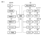
センサ57a、57b、厚さ検出器120、カウントセンサ121、第1書状センサ122、第2書状センサ127、押込み力検出センサ123は、取出し装置1の制御部200に接続され、検出信号を制御部200に出力する。この制御部200には、真空ポンプ61,71、77を駆動するドライバ202、ブロワー65を駆動するドライバ204、ACサーボモータ69、81、88を駆動するドライバ206、バルブ装置300のモータ306を駆動するドライバ208、供給機構2の駆動モータ90を駆動するドライバ107がそれぞれ接続され、制御部200は、各センサからの検出信号に応じて、各ドライバを駆動する。   The sensors 57a and 57b, the thickness detector 120, the count sensor 121, the first letter sensor 122, the second letter sensor 127, and the pushing force detection sensor 123 are connected to the control unit 200 of the take-out device 1, and the detection signal is sent to the control unit. Output to 200. The control unit 200 drives a driver 202 that drives the vacuum pumps 61, 71, 77, a driver 204 that drives the blower 65, a driver 206 that drives the AC servomotors 69, 81, 88, and a motor 306 of the valve device 300. And a driver 107 for driving the drive motor 90 of the supply mechanism 2 are connected to each other, and the control unit 200 drives each driver in accordance with a detection signal from each sensor.

図13示すように、取出し装置1は、オペレータにより手動で操作されるモード設定部340を備え、このモード設定部340は制御部200に接続されている。モード設定部340は、処理する郵便物の厚さ、あるいは、長さに応じて、バルブ装置300の吸引力を変更するモードを設定することができる。通常の形態の郵便物、例えば、所定の厚さおよび長さの郵便物の処理に用いる通常モードと、所定の値よりも薄いあるいは短い郵便物を処理する際に用いる吸引力低減モードと、を選択することができる。   As illustrated in FIG. 13, the take-out device 1 includes a mode setting unit 340 that is manually operated by an operator, and the mode setting unit 340 is connected to the control unit 200. The mode setting unit 340 can set a mode for changing the suction force of the valve device 300 according to the thickness or length of the mail to be processed. A normal mode used for processing mail pieces of a normal form, for example, a mail piece of a predetermined thickness and length, and a suction force reduction mode used for processing mail pieces thinner or shorter than a predetermined value. You can choose.

押込み力検出センサ123は、例えば、圧力センサや、レバーとバネを利用してレバーの押込み量を検出するセンサ等を用いることができ、郵便物Pが取出し位置87にどの程度が押込まれてくるかを判断する。例えば、制御部200は、押込み力検出センサ123からの検出信号により、郵便物Pの押込みが無ければ、すなわち、検出した押込み力が基準値よりも小さい場合、供給機構2を動かして、郵便物Pを前方に送りこむといった動作を促す。また、郵便物Pが押込まれ過ぎた場合には、すなわち、検出した押込み力が基準値よりも小さい場合、制御部200は、供給機構2を逆向きに作動させて郵便物Pの詰まりすぎ状態を緩和させることできる。押込み力検出センサ123は、押込み力そのものを測る場合もあれば、郵便物Pの有無を検出するだけの場合もある。   As the pushing force detection sensor 123, for example, a pressure sensor, a sensor that detects the pushing amount of the lever using a lever and a spring, or the like can be used, and how much the postal matter P is pushed into the take-out position 87. Determine whether. For example, if the postal matter P is not pushed by the detection signal from the pushing force detection sensor 123, that is, if the detected pushing force is smaller than the reference value, the control unit 200 moves the supply mechanism 2 to move the postal matter. Encourage the action of sending P forward. Further, when the postal matter P is pushed too much, that is, when the detected pushing force is smaller than the reference value, the control unit 200 operates the supply mechanism 2 in the reverse direction and the postal matter P is clogged too much. Can be relaxed. The pushing force detection sensor 123 may measure the pushing force itself, or may only detect the presence or absence of the postal matter P.

図2および図3に示すように、第1書状センサ122および第2書状センサ127は、取出し位置87あるいはその僅か上流側における紙葉類の有無を、互いに異なる方向から見て検知するセンサであり、少なくとも1つは光学センサで構成されている。本実施形態において、第1書状センサ122は、透過光を検知する透過光学センサで構成され、取出し位置87近傍に集積されている郵便物Pの面方向に検出光を当て、透過した検出光を検知するように設けられている。第1書状センサ122は、郵便物Pが第1書状センサ122の光軸上に無い有りを検出し、あるいは、郵便物Pの疎、密を検出する。例えば、取出し位置87に郵便物Pが有る場合、第1書状センサ122からの検出光は、郵便物Pの書状エッジに当たって遮られ、第1書状センサは暗(オフ)となる。これにより、第1書状センサ122は、郵便物有り情報(暗)を出力する。また、取出し位置87に郵便物Pが無い場合、検出光は、取出し位置を透過し、第1書状センサ122により検知される。これにより、第1書状センサ122は、郵便物無し情報(明)を出力する。更に、第1書状センサ122は、郵便物の厚さを検知する厚さセンサとしても機能することができる。   As shown in FIGS. 2 and 3, the first letter sensor 122 and the second letter sensor 127 are sensors that detect the presence or absence of paper sheets at the take-out position 87 or slightly upstream thereof from different directions. , At least one is constituted by an optical sensor. In the present embodiment, the first letter sensor 122 is composed of a transmissive optical sensor that detects transmitted light. The first letter sensor 122 applies detection light to the surface direction of the postal matter P accumulated near the take-out position 87, and transmits the detected light that has passed therethrough. It is provided to detect. The first letter sensor 122 detects that the postal matter P is not on the optical axis of the first letter sensor 122, or detects whether the postal matter P is sparse or dense. For example, when the postal matter P is present at the take-out position 87, the detection light from the first letter sensor 122 is blocked by hitting the letter edge of the postal matter P, and the first letter sensor is dark (off). Thereby, the first letter sensor 122 outputs postal matter presence information (dark). When there is no postal matter P at the take-out position 87, the detection light passes through the take-out position and is detected by the first letter sensor 122. Thereby, the first letter sensor 122 outputs postal matter absence information (bright). Further, the first letter sensor 122 can also function as a thickness sensor that detects the thickness of the mail.

第2書状センサ127は、郵便物Pからの反射光を検知する反射光学センサで構成されている。この第2書状センサ127は、例えば、投入部51の前面壁の近傍に設けられ、取出し位置87に位置している郵便物Pに対して郵便物の表面と交差する方向に検出光を当て、郵便物表面からの反射光を検知するように設けられている。第2書状センサ127は、例えば、取出し位置87に郵便物Pが有る場合、第2書状センサ127からの検出光は、郵便物Pの表面に当たって反射し、この反射光を検知することにより明(オン)となる。これにより、第2書状センサ127は、郵便物有り情報(明)を出力する。また、取出し位置87に郵便物Pが無い場合、第2書状センサ127は反射光を受光せず、暗(オフ)となる。これにより、第2書状センサ127は、郵便物無し情報(暗)を出力する。更に、第2書状センサ127は、長さの短い郵便物Pを検出する長さセンサとしても機能することができる。   The second letter sensor 127 is composed of a reflective optical sensor that detects reflected light from the postal matter P. The second letter sensor 127 is provided, for example, in the vicinity of the front wall of the input unit 51, and applies the detection light to the postal matter P located at the take-out position 87 in a direction intersecting the surface of the postal matter, It is provided to detect reflected light from the mail surface. For example, when the postal matter P is present at the take-out position 87, the second letter sensor 127 reflects the detection light from the second letter sensor 127 against the surface of the postal matter P, and detects the reflected light to detect light ( ON). Accordingly, the second letter sensor 127 outputs postal matter presence information (bright). When there is no postal matter P at the take-out position 87, the second letter sensor 127 does not receive the reflected light and becomes dark (off). As a result, the second letter sensor 127 outputs postal matter absence information (dark). Further, the second letter sensor 127 can also function as a length sensor that detects a postal matter P having a short length.

上記のように構成された取り出し装置1によれば、通常モードにおいて、制御部200は、駆動モータ90によりメインベルト126の走行を制御し、供給機構2による郵便物Pの供給速度あるいは送り量を制御する。第1書状センサ122および第2書状センサ127の少なくとも一方から郵便物無し情報が出力された場合、制御部200は、供給機構2の送り動作を実行し、郵便物Pを取出し位置87へ送り込む。すなわち、取出し位置87に郵便物Pが無いと検出された場合、制御部200は、郵便物Pが空か疎になり、郵便物Pの取出しが間欠的になるおそれがあると判断し、供給動作を行う。その後、制御部200は、第1書状センサ122および第2書状センサ127から郵便物有り情報が出力された時点で、供給機構2による郵便物Pの供給動作を停止する。   According to the take-out device 1 configured as described above, in the normal mode, the control unit 200 controls the travel of the main belt 126 by the drive motor 90, and determines the supply speed or feed amount of the postal matter P by the supply mechanism 2. Control. When the postal matter absence information is output from at least one of the first letter sensor 122 and the second letter sensor 127, the control unit 200 executes the feeding operation of the supply mechanism 2 and sends the postal matter P to the take-out position 87. That is, when it is detected that there is no postal matter P at the take-out position 87, the control unit 200 determines that the postal matter P becomes empty or sparse, and that the postal matter P may be taken out intermittently, and is supplied. Perform the action. Thereafter, the control unit 200 stops the mail P supply operation by the supply mechanism 2 when the mail presence information is output from the first letter sensor 122 and the second letter sensor 127.

取出し機構56は、バルブ装置300の連通孔325を第1オン位置に移動させた状態で真空ポンプ61を動作させ最大の吸引力でチャンバ52内を真空引きする。すると、ガイド60に対向したチャンバ52の開口(図示せず)、ガイド60の複数本のスリット60a、および矢印D1方向に走行する取出しベルト79の多数の吸着孔79aを介して、取出し位置87に供給された郵便物Pに負圧(図中矢印S1)が作用し、当該郵便物Pが取出しベルト79の表面に吸着される。吸着された郵便物Pは、取出しベルト79の走行に伴って取出し位置87から搬送路10上へ取出される。所定期間だけチャンバ52を吸気し、郵便物Pが取出された後、バルブ装置300の連通孔325をオフ位置に移動させ吸気を停止する。これを所定の周期で繰り返すことにより、郵便物Pを1枚ずつ取出す。この取出し機構56は、取出し位置87の郵便物Pを1枚ずつ搬送路10上へ繰り出すが、複数枚が重なった状態で搬送路10上に繰り出された場合は、分離機構54によって1枚ずつに分離する。   The take-out mechanism 56 operates the vacuum pump 61 in a state where the communication hole 325 of the valve device 300 is moved to the first ON position, and evacuates the chamber 52 with the maximum suction force. Then, an opening (not shown) of the chamber 52 facing the guide 60, a plurality of slits 60a of the guide 60, and a large number of suction holes 79a of the take-out belt 79 traveling in the direction of the arrow D1 reach the take-out position 87. A negative pressure (arrow S1 in the figure) acts on the supplied postal matter P, and the postal matter P is adsorbed on the surface of the take-out belt 79. The sucked postal matter P is taken out from the take-out position 87 onto the conveyance path 10 as the take-out belt 79 travels. After the chamber 52 is sucked in for a predetermined period and the postal matter P is taken out, the communication hole 325 of the valve device 300 is moved to the off position to stop the suction. By repeating this in a predetermined cycle, the postal matter P is taken out one by one. The take-out mechanism 56 feeds the postal matter P at the take-out position 87 one by one onto the transport path 10, but when a plurality of sheets are fed out onto the transport path 10 in a state where a plurality of sheets overlap each other, the separation mechanism 54 takes it one by one. To separate.

また、取出す郵便物(書状)Pの形態情報として、薄いあるいは短いが検出された場合、バルブ装置300は、吸気オン状態での連通孔325の位置を第1オン位置から第2オン位置にずらすことにより、配管62の流通面積を低減し吸着力を少し小さくする。これにより、郵便物Pが薄くて透気しやすい場合でも、2枚目の郵便物まで吸着するのを防止し、また、短い郵便物が取出されて抜けた直後の2枚目の郵便物を吸着する力を抑えることにより、2枚目の郵便物が前に出て行くことを低減する。   Further, when thin or short is detected as the form information of the postal matter (letter) P to be taken out, the valve device 300 shifts the position of the communication hole 325 in the intake on state from the first on position to the second on position. As a result, the flow area of the pipe 62 is reduced and the adsorption force is reduced slightly. As a result, even if the mail piece P is thin and easily permeable, the second mail piece is prevented from being adsorbed, and the second mail piece immediately after the short mail piece is taken out is removed. By suppressing the adsorbing force, it is possible to reduce the second mail piece from moving forward.

郵便物、例えば、書状の厚さ検出方法、長さ検出方法について説明する。
<厚さ検出方法>
1)オペレータが手動によりモード設定部340の切替えを行う。
装置のオペレータが、供給部に装填する郵便物に対して、予めモードなどを選ぶことにより、厚さに適したモードを設定する。例えば、薄いあるいは短い郵便物を装填した場合は、モード設定部340により吸気力低減モードを設定する。
A method for detecting the thickness and length of a mail, for example, a letter will be described.
<Thickness detection method>
1) The operator manually switches the mode setting unit 340.
The operator of the apparatus sets a mode suitable for the thickness by selecting a mode or the like in advance for the mail to be loaded in the supply unit. For example, when a thin or short mail piece is loaded, the mode setting unit 340 sets the intake force reduction mode.

2)厚さ検出器により郵便物の厚さを検出する。 2) The thickness of the mail is detected by the thickness detector.

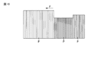
取出された郵便物Pの厚さを厚さ検出器120で計測することにより、投入部51の取出し位置87近傍にある郵便物Pの厚さを予想する。厚さ検出器120は、レーザー変位計(光学式)による距離測定などによる方法や、他にも接触式による厚さ検出方法など各種考えられる。図14に示すように、厚さ検出器120で各々の郵便物の厚さを測定し、単位時間T0当たりに通過した郵便物の厚さの単位時間平均値THを算出する。ここで、図15に示すように、厚さの異なる郵便物がバルク状態で投入部51に装填されている場合、厚さ情報がほぼ一定であると予想され、ここで算出される平均値THと、投入部51の取出し位置87にいる郵便物の各々の厚さとは同じであると考えることができる。   By measuring the thickness of the picked-up mail piece P with the thickness detector 120, the thickness of the mail piece P in the vicinity of the pick-up position 87 of the input unit 51 is predicted. Various thickness detectors 120 are conceivable, such as a distance measurement method using a laser displacement meter (optical type) or a contact type thickness detection method. As shown in FIG. 14, the thickness detector 120 measures the thickness of each piece of mail, and calculates the unit time average value TH of the thickness of the piece of mail that has passed per unit time T0. Here, as shown in FIG. 15, when mail pieces having different thicknesses are loaded in the input unit 51 in a bulk state, the thickness information is expected to be almost constant, and the average value TH calculated here is calculated. It can be considered that the thicknesses of the mail pieces at the take-out position 87 of the input unit 51 are the same.

3)投入部51の郵便物送りなどの制御に用いる第1書状センサ122の信号を用いる。 3) The signal of the first letter sensor 122 used for controlling the mail feeding of the input unit 51 is used.

投入部51に装填されている郵便物の疎密状態を検出して供給の送りを制御する第1書状センサ122の信号(明暗情報)を用いて郵便物の厚さを検出する。投入部51に薄い郵便物のバルクが装填されている場合、郵便物間の隙間が開きにくく、第1書状センサ122の信号は暗時間が長くなる傾向がある。単位時間当たりの第1書状センサ122の暗時間を積分し、常に積分値を監視する。例えば、監視のサンプリング周期が1msで、暗時間の積分値>0.9(90%)になった場合に、制御部200は、所定の厚さよりも薄い薄物の郵便物のバルクが取出し位置87に存在すると判断する。   The thickness of the postal matter is detected using a signal (light / dark information) of the first letter sensor 122 that detects the density of the postal matter loaded in the input unit 51 and controls the feeding of the postage. When a thin bulk of mail is loaded in the input unit 51, the gap between the mails is difficult to open, and the signal of the first letter sensor 122 tends to have a long dark time. The dark time of the first letter sensor 122 per unit time is integrated, and the integrated value is constantly monitored. For example, when the monitoring sampling period is 1 ms and the integrated value of dark time is greater than 0.9 (90%), the control unit 200 determines that the bulk of a mail piece that is thinner than a predetermined thickness is the take-out position 87. It is determined that it exists.

<長さ検出方法>
1)オペレータが手動によりモード設定部340の切替えを行う。
装置のオペレータが、投入部51に装填する郵便物に対して、予めモードなどを選ぶことにより、長さに適したモードを設定する。例えば、所定の長さよりも短い郵便物を装填した場合は、モード設定部340により吸気力低減モードを設定する。
<Length detection method>
1) The operator manually switches the mode setting unit 340.
The operator of the apparatus sets a mode suitable for the length by selecting a mode or the like in advance for the mail to be loaded in the input unit 51. For example, when a mail piece shorter than a predetermined length is loaded, the intake force reduction mode is set by the mode setting unit 340.

2)取出した郵便物を検知するセンサを用いる。
取出された郵便物Pの長さを、何らかの光学センサ、例えば、カウントセンサ121や厚さ検出器120により計測し、投入部51の取出し位置87にいる郵便物の長さを予想する。ここで、図15に示すように、長さの異なる複数種類の郵便物がバルク状態で装填されている場合、カウントセンサ121や厚さ検出器120で検出された長さ情報がほぼ一定であると予想され、投入部51の取出し位置87にいる郵便物の書状長さは検出結果と同じであると考えることができる。
2) Use a sensor that detects the mail that has been taken out.
The length of the mail piece P taken out is measured by some optical sensor, for example, the count sensor 121 or the thickness detector 120, and the length of the mail piece at the pick-up position 87 of the input unit 51 is predicted. Here, as shown in FIG. 15, when a plurality of types of mail pieces having different lengths are loaded in a bulk state, the length information detected by the count sensor 121 and the thickness detector 120 is substantially constant. Therefore, it can be considered that the letter length of the mail piece at the take-out position 87 of the input unit 51 is the same as the detection result.

3)第2書状センサ(反射センサ)127等を用いる。
図2および図3に示すように、第2書状センサ127で取出し位置87における郵便物Pを検出する。取出し位置87近傍の郵便物が所定の長さよりも短い場合には、第2書状センサ127で郵便物を検出することができず、しばらく短い郵便物が続くと予想することができる。
3) A second letter sensor (reflection sensor) 127 or the like is used.
As shown in FIGS. 2 and 3, the second letter sensor 127 detects the postal matter P at the take-out position 87. If the postal matter in the vicinity of the pick-up position 87 is shorter than the predetermined length, the postal matter cannot be detected by the second letter sensor 127, and it can be expected that a short postal matter will continue for a while.

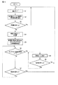
上述した郵便物の厚さ検出および長さ検出に応じて、バルブ装置300は、郵便物の吸着力を制御する。バルブ装置300の基本動作は、例えば、以下の通りとなる。図16に示すように、通常モードが設定されている場合、まず、バルブ装置300を通常モードで動作させる(S1)。すなわち、吸気オン時、遮蔽板304の連通孔325を第1オン位置に移動させ、配管62の長孔377a、377bと同軸的に配置し、ほぼ最大の吸着力にて郵便物Pを吸着する。   In response to the above-described thickness detection and length detection of the mail piece, the valve device 300 controls the adsorption force of the mail piece. The basic operation of the valve device 300 is, for example, as follows. As shown in FIG. 16, when the normal mode is set, first, the valve device 300 is operated in the normal mode (S1). That is, when the intake air is on, the communication hole 325 of the shielding plate 304 is moved to the first on position, and is arranged coaxially with the long holes 377a and 377b of the pipe 62, so that the postal matter P is adsorbed with almost the maximum adsorption force. .

取出し動作の間、制御部200は、第1書状センサ122より取出し位置87での郵便物の疎密を検出し、単位時間当たりの明暗の積分値を監視する(S2)。そして、単位時間に対する暗時間の積分値が一定値αよりも小さいか確認し(S3)、αよりも小さい場合には、通常厚さの郵便物であると判断して通常モードを継続する。   During the take-out operation, the control unit 200 detects the density of the mail at the take-out position 87 from the first letter sensor 122 and monitors the integrated value of light and dark per unit time (S2). Then, it is confirmed whether the integrated value of the dark time with respect to the unit time is smaller than the constant value α (S3). If smaller than α, it is determined that the mail piece has a normal thickness and the normal mode is continued.

単位時間に対する暗時間の積分値が一定値(α)よりも大きい場合、制御部200は取出し位置87にある郵便物が所定の厚さよりも薄くなったと予測し、バルブ装置300の動作を吸着力低減モードに変更する(S4)。吸着力低減モードにおいて、バルブ装置300は、吸気オン時、遮蔽板304の連通孔325を第2オン位置に移動させ、通常モード時よりも吸着力を小さくする。   When the integral value of the dark time with respect to the unit time is larger than a certain value (α), the control unit 200 predicts that the mail piece at the take-out position 87 is thinner than a predetermined thickness, and the operation of the valve device 300 is determined as the suction force. The mode is changed to the reduction mode (S4). In the suction force reduction mode, the valve device 300 moves the communication hole 325 of the shielding plate 304 to the second on position when the intake air is on, so that the suction force is smaller than that in the normal mode.

吸着力低減モードに移行したことにより、異常が起きていないかの確認は、例えば、搬送路上のカウントセンサ121の信号を確認することにより行う(S5)。制御部200は、カウントセンサ121が一定時間T、例えば、50ms、連続“明”とならない場合、郵便物が正常に取出されてカウントセンサ121を通過していると判断し(S6)、吸着力低減モードを継続する。この間、制御部200は、第1書状センサ122の信号を監視し、単位時間に対する暗時間の積分値が一定値βよりも小さいか否かを判断する(S7)。ここで、積分値βは、前述した積分値αよりも小さい(β<α)ことが望ましい。一例として、α=0.9、β=0.8としている。   Whether or not an abnormality has occurred due to the shift to the suction force reduction mode is confirmed by, for example, confirming the signal of the count sensor 121 on the conveyance path (S5). When the count sensor 121 is not continuously “bright” for a certain time T, for example, 50 ms, the control unit 200 determines that the postal matter has been taken out normally and has passed through the count sensor 121 (S6). Continue in reduced mode. During this time, the control unit 200 monitors the signal of the first letter sensor 122 and determines whether or not the integrated value of the dark time with respect to the unit time is smaller than the constant value β (S7). Here, it is desirable that the integral value β is smaller than the aforementioned integral value α (β <α). As an example, α = 0.9 and β = 0.8.

積分値>βの場合、制御部200は、薄い郵便物が続いていると判断し、S6に戻り、吸着力低減モードを継続する。また、積分値<βとなった場合、制御部200は、取出し位置における郵便物が通常の厚さの郵便物に戻ったと予測し、バルブ装置300の動作を通常モードに戻す(S8)。ここで、α=βとすると、モード変更した直後に元に戻る条件になってしまう場合があり、不安定な制御となる虞がある。そのため、ここでは、αおよびβの値をずらし、β<αに設定している。   When the integral value> β, the control unit 200 determines that a thin mail piece continues, returns to S6, and continues the suction force reduction mode. When the integral value <β, the control unit 200 predicts that the mail piece at the take-out position has returned to a normal thickness mail piece, and returns the operation of the valve device 300 to the normal mode (S8). Here, if α = β, there may be a condition for returning to the original state immediately after the mode change, which may result in unstable control. Therefore, here, the values of α and β are shifted, and β <α is set.

前述したステップS6において、カウントセンサ121が一定時間T以上、連続“明”のままとなっている場合、制御部200は、何らかの影響で郵便物を正常に取出せない(異常状態)と判断し、通常モードに移行する(S7)。その後、制御部200は、第1書状センサ122の信号を監視し、単位時間に対する暗時間の積分値が一定値βよりも小さいか否かを判断する(S8)。積分値>βの場合、制御部200は、ステップS8に戻り、通常モードを継続する。また、積分値<βとなった場合、制御部200は、取出し位置における郵便物が通常の厚さの郵便物に戻ったと予測し、バルブ装置300の動作を通常モードS1に戻す。   In step S6 described above, when the count sensor 121 remains “bright” continuously for a certain time T or longer, the control unit 200 determines that the mail cannot be normally taken out due to some influence (abnormal state), Transition to the normal mode (S7). Thereafter, the control unit 200 monitors the signal of the first letter sensor 122 and determines whether or not the integral value of the dark time with respect to the unit time is smaller than the constant value β (S8). When the integral value> β, the control unit 200 returns to step S8 and continues the normal mode. When the integral value <β, the control unit 200 predicts that the mail piece at the take-out position has returned to a normal thickness mail piece, and returns the operation of the valve device 300 to the normal mode S1.

ステップS6において異常状態であると判断された後、そのまま第1書状センサ122の検知情報により郵便物が所定値よりも薄いと判断してしまうと、異常処理を繰り返す可能性が高くなる。そのため、本実施形態では、異常状態検出後、第1書状センサ122により、通常厚さの郵便物に戻ったことを確認するまでは、吸着力低減モードに移行することが無いようにしている。   If it is determined in step S6 that the mail is in an abnormal state, and the postal matter is determined to be thinner than the predetermined value based on the detection information of the first letter sensor 122, the possibility of repeating the abnormal process increases. For this reason, in the present embodiment, after the abnormal state is detected, the first letter sensor 122 does not shift to the suction force reduction mode until it is confirmed that the mail has returned to the normal thickness.

なお、郵便物の厚さ検知は、第1書状センサの検出情報による場合に限らず、前述した厚さ検出器120等の他のセンサによる検出情報に基づいて行ってもよい。また、上記説明では、郵便物の厚さ検知に応じてバルブ装置300の動作モードを変更したが、これに限らず、前述した長さ検出方法により検出した郵便物の長さに応じて、動作モードを変更してもよい。例えば、所定長さよりも短い郵便物であることが検知された場合、バルブ装置300の動作モードを通常モードから吸着力低減モードに変更する構成としてもよい。   The thickness of the mail piece is not limited to the case of using the detection information of the first letter sensor, but may be based on the detection information of another sensor such as the thickness detector 120 described above. In the above description, the operation mode of the valve device 300 is changed according to the thickness detection of the mail piece. However, the operation mode is not limited to this, and the operation is performed according to the length of the mail piece detected by the length detection method described above. The mode may be changed. For example, when it is detected that the mail is shorter than a predetermined length, the operation mode of the valve device 300 may be changed from the normal mode to the adsorption force reduction mode.

以上のように構成された取出し装置1を備えた紙葉類処理装置によれば、取出し位置にある郵便物あるいは取出された郵便物の厚さ、あるいは長さを検出し、その情報に基づいて、バルブ装置を制御して吸着力を調整することにより、所定よりも厚い郵便物あるいは所定よりも短い郵便物でも吸着力の悪影響を受けることなく多重取出しを低減することができる。これにより、紙葉類の多重取り出しを低減し、安定した紙葉類の取出しが可能な紙葉類の取出し装置およびこれを備える紙葉類処理装置を提供することができる。   According to the paper sheet processing apparatus provided with the take-out device 1 configured as described above, the thickness or length of the postal matter at the takeout position or the postal matter taken out is detected, and based on the information. By adjusting the suction force by controlling the valve device, it is possible to reduce multiple pick-up without being adversely affected by the suction force even for mail pieces that are thicker than predetermined or mail pieces that are shorter than predetermined. Accordingly, it is possible to provide a paper sheet take-out apparatus that can reduce the multiple take-out of paper sheets and stably take out the paper sheets, and a paper sheet processing apparatus including the same.

次に、他の実施形態に係る取出し装置について説明する。
前述した実施形態では、単純に薄いあるいは短い紙葉類などの場合に、バルブ装置300における遮蔽板304の連通孔325の位置をずらして、吸着エアーを絞ることにより多重取りを防いでいるが、エアーの最大吸着力が下がることにより、紙葉類が取出しベルト79に吸着されて繰り出されるまでの一連の動作が遅れる可能性も考えられる。
Next, a take-out device according to another embodiment will be described.
In the above-described embodiment, in the case of simple paper sheets or the like, the multiple holes are prevented by shifting the position of the communication hole 325 of the shielding plate 304 in the valve device 300 and narrowing the suction air. It is conceivable that a series of operations until paper sheets are attracted to the take-out belt 79 and fed out are delayed due to a decrease in the maximum air suction force.

他の実施形態によれば、通常モードにおいて、バルブ装置300は前記実施形態と同様に動作する。すなわち、図10(a)で示したように、吸気ON時、バルブ装置300の遮蔽板304は、モータ306により回転され、連通孔325がシールド部材335、336の長孔337a、337bと同軸的に重なるオン位置(第1オン位置)に移動される。これにより、下流側の配管62aと上流側の配管62bが連通孔325を通して連通することにより、配管62を開放し、空気を流通可能とする。図17a、図17bは、その際の吸着機構のエアー吸着圧力の変化および遮蔽板304の位相角度を示している。   According to another embodiment, in the normal mode, the valve device 300 operates in the same manner as in the previous embodiment. That is, as shown in FIG. 10A, when the intake air is ON, the shielding plate 304 of the valve device 300 is rotated by the motor 306, and the communication hole 325 is coaxial with the long holes 337a and 337b of the shielding members 335 and 336. Is moved to the on position (first on position) overlapping with the. As a result, the downstream pipe 62a and the upstream pipe 62b communicate with each other through the communication hole 325, thereby opening the pipe 62 and allowing air to flow. 17a and 17b show the change in the air adsorption pressure of the adsorption mechanism and the phase angle of the shielding plate 304 at that time.

また、図10(b)で示したように、吸気OFF時、遮蔽板304が約90度回転され連通孔325がオフ位置に移動し、遮蔽板304によって配管62が遮蔽され、空気の吸気が停止される。   Further, as shown in FIG. 10B, when the intake air is OFF, the shielding plate 304 is rotated about 90 degrees, the communication hole 325 is moved to the OFF position, the piping 62 is shielded by the shielding plate 304, and the intake of air is performed. Stopped.

一方、他の実施形態によれば、吸着力低減モードにおいて、吸着オンの指令が出た場合、図18に示すように、遮蔽板304はモータ306により吸着オフ状態から回転され、連通孔325は一旦、第1オン位置((長孔337a、337bと同軸的に重なる位置)を通り、第2オン位置(長孔337a、337bからわずかにずれた位置)を目標値に移動する。図19は、吸着機構のエアー吸着圧力の変化および遮蔽板304の位相角度を示している。連通孔325が第1オン位置を通過した後、第2オン位置へ至ることにより、書状吸着時に吸着圧力が一瞬ピークまで上がった後、低減した吸着圧力となる。このように、書状吸着時に吸着圧力が一瞬ピークまで上がるので、1枚目の郵便物が吸着ベルト79に吸着されるときの動作遅れは軽減される。その後、吸着圧力が下がることにより、2枚目の郵便物が吸着されることなく多重枚取りは防がれる。   On the other hand, according to another embodiment, when the suction-on command is issued in the suction force reduction mode, the shielding plate 304 is rotated from the suction-off state by the motor 306 as shown in FIG. Once it passes through the first ON position (position overlapping the long holes 337a and 337b coaxially), the second ON position (position slightly displaced from the long holes 337a and 337b) is moved to the target value. 3 shows the change in the air adsorption pressure of the adsorption mechanism and the phase angle of the shielding plate 304. After the communication hole 325 passes through the first on position, it reaches the second on position, so that the adsorption pressure is instantaneously absorbed during letter adsorption. After reaching the peak, the suction pressure is reduced, so that the suction pressure rises to the peak for a moment when the letter is picked up, so that the operation delay when the first mail piece is picked up by the suction belt 79 is delayed. Is reduced. Then, by the suction pressure decreases, postal second sheet is prevented multiplex sheets up without being adsorbed.

上記のように構成された他の実施形態においても、紙葉類の多重取り出しを低減し、安定した紙葉類の取出しが可能な紙葉類の取出し装置およびこれを備える紙葉類処理装置を提供することができる。   In another embodiment configured as described above, there is provided a paper sheet take-out apparatus capable of reducing the multiple take-out of paper sheets and stably taking out the paper sheets, and a paper sheet processing apparatus including the same. Can be provided.

本発明は上記実施形態そのままに限定されるものではなく、実施段階ではその要旨を逸脱しない範囲で構成要素を変形して具体化できる。また、上記実施形態に開示されている複数の構成要素の適宜な組み合わせにより、種々の発明を形成できる。例えば、実施形態に示される全構成要素から幾つかの構成要素を削除してもよい。さらに、異なる実施形態にわたる構成要素を適宜組み合わせてもよい。   The present invention is not limited to the above-described embodiments as they are, and can be embodied by modifying the constituent elements without departing from the scope of the invention in the implementation stage. In addition, various inventions can be formed by appropriately combining a plurality of components disclosed in the embodiment. For example, some components may be deleted from all the components shown in the embodiment. Furthermore, constituent elements over different embodiments may be appropriately combined.

なお、バルブ装置は、連通孔を有する遮蔽板の回転位置を変更することにより配管の流通面積を変更し吸着力を変更する構成としたが、これに限らず、配管の流通面積を変更できる構成であればよく、例えば、プランジャ等の直動式のバルブ装置を用いても良い。紙葉類は、郵便物に限らず、他の種々の紙葉類に適用可能である。   The valve device is configured to change the flow area of the piping by changing the rotational position of the shielding plate having the communication hole and change the adsorption force, but the configuration is not limited to this, and the configuration can change the flow area of the pipe. For example, a direct-acting valve device such as a plunger may be used. Paper sheets are not limited to mail, but can be applied to other various paper sheets.

1…取出し装置、2…供給機構、10…搬送路、51…投入部、53…吸引機構、
54…分離機構、55…補助機構、56…取出し機構、58…搬送機構、
61…真空ポンプ(空気吸引源)、62…配管、79…取出しベルト、
120…厚さ検知器、122…第1書状センサ、127…第2書状センサ、
200…制御部、300…バルブ装置、304…遮蔽板、306…モータ、
325…連通孔、337a、337b…長孔、P…郵便物
DESCRIPTION OF SYMBOLS 1 ... Extraction device, 2 ... Supply mechanism, 10 ... Conveyance path, 51 ... Input part, 53 ... Suction mechanism,
54 ... separation mechanism, 55 ... auxiliary mechanism, 56 ... take-out mechanism, 58 ... transport mechanism,
61 ... Vacuum pump (air suction source), 62 ... Piping, 79 ... Take-out belt,
120 ... thickness detector, 122 ... first letter sensor, 127 ... second letter sensor,
200 ... Control unit, 300 ... Valve device, 304 ... Shielding plate, 306 ... Motor,
325 ... Communication hole, 337a, 337b ... Long hole, P ... Mail

Claims (7)

複数枚重ねて載置された紙葉類をその重ね方向に移動させて移動方向先端にある紙葉類を取出し位置へ供給する供給機構と、
前記取出し位置に供給された紙葉類を前記投入部から1枚ずつ取出す取出し機構と、
前記紙葉類の形態を検出する検出器と、を備え、
前記取出し機構は、前記取出し位置にある紙葉類を取出す取出し部材と、前記取出し部材を通して吸気し前記紙葉類を取出し部材に吸着する空気吸引源と、前記取出し部材と空気吸引源との間に設けられ吸着力を調整するバルブ装置と、前記検出器により検出された紙葉類の形態に応じて、吸着時の吸着力を前記バルブ装置により変更する制御部と、を備えている紙葉類の取出し装置。
A supply mechanism for moving a plurality of stacked paper sheets in the stacking direction and supplying the paper sheets at the leading end in the moving direction to the take-out position;
An unloading mechanism for unloading the sheets supplied to the unloading position one by one from the loading section;
A detector for detecting the form of the paper sheet,
The take-out mechanism includes a take-out member that takes out the paper sheet at the take-out position, an air suction source that sucks air through the take-out member and adsorbs the paper sheet to the take-out member, and a space between the take-out member and the air suction source. And a control unit that changes the suction force at the time of suction by the valve device according to the form of the paper sheet detected by the detector. Take-out device.
前記検出器は、前記紙葉類の厚さを検知する厚さ検知器を備え、前記制御部は、前記厚さ検知器により、所定の厚さよりも薄い紙葉類が検知された際、吸着時の吸着力を前記バルブ装置により変更する請求項1に記載の紙葉類の取出し装置。   The detector includes a thickness detector that detects the thickness of the paper sheet, and the control unit adsorbs when a paper sheet thinner than a predetermined thickness is detected by the thickness detector. The paper sheet take-out device according to claim 1, wherein the suction force at the time is changed by the valve device. 前記検出器は、前記紙葉類の長さを検知する長さ検知器を備え、前記制御部は、前記長さ検知器により、所定の長さよりも短い紙葉類が検知された際、吸着時の吸着力を前記バルブ装置により変更する請求項1又は2に記載の紙葉類の取出し装置。   The detector includes a length detector that detects the length of the paper sheet, and the control unit adsorbs when a paper sheet shorter than a predetermined length is detected by the length detector. The paper sheet take-out device according to claim 1 or 2, wherein the suction force at the time is changed by the valve device. 前記バルブ装置は、前記空気吸引源と前記取出し部材とを繋ぐ配管を開閉する遮蔽部材を有し、所定の厚さよりも薄い紙葉類が検知された際、あるいは、所定の長さよりも短い紙葉類が検知された際、前記遮蔽部材により配管の流通面積を小さくし、吸着時の吸着力を通常時よりも弱くする請求項1ないし3のいずれか1項に記載の紙葉類の取出し装置。   The valve device has a shielding member that opens and closes a pipe connecting the air suction source and the take-out member, and when a paper sheet thinner than a predetermined thickness is detected, or a paper shorter than a predetermined length The take-out of paper sheets according to any one of claims 1 to 3, wherein when the leaves are detected, the flow area of the pipe is reduced by the shielding member so that the suction force at the time of suction is weaker than normal. apparatus. 前記遮蔽部材は、連通孔を有し、この連通孔が前記配管と同軸的に重なる第1オン位置と、前記連通孔が前記配管と僅かにずれて重なる第2オン位置と、へ移動可能に設けられ、前記遮蔽部材は、通常の吸着時、第1オン位置に移動され、前記所定の厚さよりも薄い紙葉類が検知された際、あるいは、前記所定の長さよりも短い紙葉類が検知された際、吸着時に前記第2オン位置へ移動される請求項4に記載の紙葉類の取出し装置。   The shielding member has a communication hole, and the communication hole is movable to a first on position where the communication hole overlaps the pipe coaxially and a second on position where the communication hole overlaps with the pipe slightly shifted. The shield member is moved to the first ON position during normal suction, and when a paper sheet thinner than the predetermined thickness is detected, or a paper sheet shorter than the predetermined length is detected. The sheet take-out device according to claim 4, wherein when the sheet is detected, the sheet is moved to the second ON position during suction. 前記バルブ装置は、前記所定の厚さよりも薄い紙葉類が検知された際、あるいは、前記所定の長さよりも短い紙葉類が検知された際、吸着時に、吸着力が最大になる第1オン位置を一旦通過したのちに吸着力が弱まる第2オン位置に制御される請求項3に記載の紙葉類の取出し装置。   The valve device has a first suction force that is maximized when a paper sheet thinner than the predetermined thickness is detected or when a paper sheet shorter than the predetermined length is detected. The paper sheet take-out device according to claim 3, wherein the paper sheet take-out device is controlled to a second on position in which the suction force is weakened after passing the on position once. 請求項1ないし6のいずれか1項に記載の紙葉類の取出し装置と、
前記取出し装置により取出された紙葉類を判別する判別装置と、
前記判別装置による判別に応じて前記紙葉類を振り分ける振分け機構と、
前記振り分けられた紙葉類を集積する集積部と、
を備える紙葉類処理装置。
The paper sheet take-out device according to any one of claims 1 to 6,
A discriminating device for discriminating paper sheets taken out by the taking-out device;
A distribution mechanism that distributes the paper sheets according to the determination by the determination device;
An accumulating unit for accumulating the sorted paper sheets;
A paper sheet processing apparatus comprising:
JP2011117033A 2011-05-25 2011-05-25 Paper sheet takeout device and paper sheet processing device provided with the same Withdrawn JP2012246071A (en)

Priority Applications (1)

Application Number Priority Date Filing Date Title
JP2011117033A JP2012246071A (en) 2011-05-25 2011-05-25 Paper sheet takeout device and paper sheet processing device provided with the same

Applications Claiming Priority (1)

Application Number Priority Date Filing Date Title
JP2011117033A JP2012246071A (en) 2011-05-25 2011-05-25 Paper sheet takeout device and paper sheet processing device provided with the same

Publications (1)

Publication Number Publication Date
JP2012246071A true JP2012246071A (en) 2012-12-13

Family

ID=47466933

Family Applications (1)

Application Number Title Priority Date Filing Date
JP2011117033A Withdrawn JP2012246071A (en) 2011-05-25 2011-05-25 Paper sheet takeout device and paper sheet processing device provided with the same

Country Status (1)

Country Link
JP (1) JP2012246071A (en)

Cited By (1)

* Cited by examiner, † Cited by third party
Publication number Priority date Publication date Assignee Title
CN115078211A (en) * 2022-05-28 2022-09-20 成都市建科院工程质量检测有限公司 Building material detection device

Cited By (1)

* Cited by examiner, † Cited by third party
Publication number Priority date Publication date Assignee Title
CN115078211A (en) * 2022-05-28 2022-09-20 成都市建科院工程质量检测有限公司 Building material detection device

Similar Documents

Publication Publication Date Title
JP5509125B2 (en) Paper sheet take-out apparatus and paper sheet processing apparatus provided with the same
EP2301869B1 (en) Paper sheet pick up device
KR100902983B1 (en) Paper sheet separating and take-out device
US4893804A (en) Apparatus for feeding sheet articles
JP4734418B2 (en) Paper sheet take-out apparatus, paper sheet processing apparatus, and paper sheet take-out method
JP3471651B2 (en) Sheet feeding apparatus and sheet feeding method using the sheet feeding apparatus
JP2008280139A (en) Paper sheet separating and taking out apparatus and control method thereof
JP2008273666A (en) Paper sheet take-out device
JP2011225295A (en) Sheet handling apparatus
JP4881206B2 (en) Paper sheet separating and taking out device
JP5377237B2 (en) Paper sheet take-out device
JP2012246071A (en) Paper sheet takeout device and paper sheet processing device provided with the same
CN103303702B (en) Paper unloading device and paper unloading method
JP2009051657A (en) Paper sheet take-out device
JP6304927B2 (en) Paper sheet take-out device and paper sheet take-out method
JPH07252003A (en) Paper sheet inspection device

Legal Events

Date Code Title Description
RD04 Notification of resignation of power of attorney

Free format text: JAPANESE INTERMEDIATE CODE: A7424

Effective date: 20131205

RD04 Notification of resignation of power of attorney

Free format text: JAPANESE INTERMEDIATE CODE: A7424

Effective date: 20131212

RD04 Notification of resignation of power of attorney

Free format text: JAPANESE INTERMEDIATE CODE: A7424

Effective date: 20131219

RD04 Notification of resignation of power of attorney

Free format text: JAPANESE INTERMEDIATE CODE: A7424

Effective date: 20131226

RD04 Notification of resignation of power of attorney

Free format text: JAPANESE INTERMEDIATE CODE: A7424

Effective date: 20140109

A300 Withdrawal of application because of no request for examination

Free format text: JAPANESE INTERMEDIATE CODE: A300

Effective date: 20140805