JP2012246867A - Idling stop control device - Google Patents
Idling stop control device Download PDFInfo
- Publication number
- JP2012246867A JP2012246867A JP2011120415A JP2011120415A JP2012246867A JP 2012246867 A JP2012246867 A JP 2012246867A JP 2011120415 A JP2011120415 A JP 2011120415A JP 2011120415 A JP2011120415 A JP 2011120415A JP 2012246867 A JP2012246867 A JP 2012246867A
- Authority
- JP
- Japan
- Prior art keywords
- idle stop
- battery
- prohibition
- internal combustion
- combustion engine
- Prior art date
- Legal status (The legal status is an assumption and is not a legal conclusion. Google has not performed a legal analysis and makes no representation as to the accuracy of the status listed.)
- Withdrawn
Links
Images
Landscapes
- Output Control And Ontrol Of Special Type Engine (AREA)
- Control Of Vehicle Engines Or Engines For Specific Uses (AREA)
Abstract
【課題】アイドルストップ実行頻度の低下を防止して、燃費性能の向上を図る。
【解決手段】アイドルストップ条件が成立したら内燃機関を停止するアイドルストップを実行し、アイドルストップ中に再始動条件が成立したら内燃機関を再始動するアイドルストップ制御装置1において、その運行の初回始動時にバッテリ電圧に基づいてバッテリ出力の低下を判定するバッテリ出力低下判定部S100と、バッテリ出力が低下していると判定したときにアイドルストップを禁止するアイドルストップ禁止部S110と、バッテリ充電量が内燃機関4の再始動に必要な出力を発生し得る充電量として予め設定した禁止解除用判定値B以上となった場合にアイドルストップの禁止を解除する禁止解除部S130と、を備える。
【選択図】図2An object of the present invention is to improve fuel efficiency by preventing a decrease in idle stop execution frequency.
An idle stop control device that executes an idle stop for stopping an internal combustion engine when an idle stop condition is satisfied, and restarts the internal combustion engine when a restart condition is satisfied during the idle stop, at the first start of the operation. A battery output decrease determination unit S100 that determines a decrease in battery output based on the battery voltage, an idle stop prohibition unit S110 that prohibits an idle stop when it is determined that the battery output is decreasing, and a battery charge amount is an internal combustion engine And a prohibition canceling unit S130 that cancels the prohibition of idling stop when the charge amount that can generate the output required for the restart is equal to or greater than the prohibition determination value B set in advance.
[Selection] Figure 2
Description
本発明は、車両の運転状態に応じて内燃機関を停止及び再始動させるアイドルストップ制御装置に関する。 The present invention relates to an idle stop control device that stops and restarts an internal combustion engine in accordance with a driving state of a vehicle.
燃費性能や環境性能等の向上を目的として、車両運転中に所定のアイドルストップ条件が成立したら内燃機関を停止(以下、アイドルストップという)し、アイドルストップ中に復帰条件が成立したら内燃機関を再始動させる、いわゆるアイドルストップ制御が知られている。 For the purpose of improving fuel efficiency and environmental performance, the internal combustion engine is stopped (hereinafter referred to as idle stop) when a predetermined idle stop condition is satisfied during vehicle operation, and is restarted when the return condition is satisfied during idle stop. A so-called idle stop control for starting is known.
ところで、バッテリ電圧がスタータモータを駆動できない程度まで低下している状態でアイドルストップすると、再始動の条件が成立しても内燃機関を再始動させることができなくなる。このように、バッテリの状態によってはアイドルストップを禁止する必要がある。バッテリの状態に応じたアイドルストップの禁止・許可の判定は、例えば特許文献1に記載されている。特許文献1では、アイドルストップの禁止・許可を判定する閾値としてのバッテリ電圧を予め設定しておき、車両運行の初回始動時における所定期間中のバッテリ電圧の最小値と閾値とを比較している。そして、バッテリ電圧の最小値が閾値より低くなった場合には、それ以降のアイドルストップを禁止している。
By the way, if the engine is idle-stopped in a state where the battery voltage is lowered to such an extent that the starter motor cannot be driven, the internal combustion engine cannot be restarted even if the restart condition is satisfied. Thus, it is necessary to prohibit idle stop depending on the state of the battery. Determination of prohibition / permission of idle stop according to the state of the battery is described in
しかしながら、特許文献1ではその運行における初回始動時の判定でアイドルストップが禁止されると、その運行終了までアイドルストップは禁止されたままとなる。このため、例えば走行中にバッテリ充電量が増加する等して、アイドルストップを実行可能なバッテリ電圧になっているにもかかわらず、アイドルストップを実行できない状況が生じ得る。すなわち、アイドルストップを実行する頻度が低下して、燃費性能向上等の効果が得られなくおそれがある。
However, in
そこで、本発明では、バッテリの状態に応じてアイドルストップの禁止と許可を切り替えることで、アイドルストップの頻度を確保して、燃費性能を向上し得る制御装装置を提供することを目的とする。 Therefore, an object of the present invention is to provide a control device that can improve the fuel efficiency by ensuring the frequency of idle stop by switching between prohibition and permission of idle stop according to the state of the battery.
本発明のアイドルストップ制御装置は、アイドルストップ条件が成立したら内燃機関を停止するアイドルストップを実行し、前記アイドルストップ中に再始動条件が成立したら内燃機関を再始動する。そして、その運行の初回始動時にバッテリ電圧に基づいてバッテリ出力の低下を判定するバッテリ出力低下判定部と、バッテリ出力が低下していると判定したときにアイドルストップを禁止するアイドルストップ禁止部とを備える。さらに、バッテリ充電量が内燃機関の再始動に必要な出力を発生し得る充電量として予め設定した禁止解除用判定値以上となった場合にアイドルストップの禁止を解除する禁止解除部を備える。 The idle stop control device of the present invention executes an idle stop for stopping the internal combustion engine when the idle stop condition is satisfied, and restarts the internal combustion engine when the restart condition is satisfied during the idle stop. And a battery output decrease determination unit that determines a decrease in battery output based on the battery voltage at the first start of the operation, and an idle stop prohibition unit that prohibits idle stop when it is determined that the battery output is decreasing. Prepare. In addition, a prohibition canceling section is provided that cancels the prohibition of idle stop when the battery charge amount is equal to or higher than a prohibition determination value set in advance as a charge amount capable of generating an output necessary for restarting the internal combustion engine.
本発明によれば、禁止解除部を備えるので、初回始動時の判定でアイドルストップが禁止された場合でも、バッテリが充電されて再始動に必要な出力を発生し得るようになったらアイドルストップを実行することができる。その結果、アイドルストップの頻度を確保して、燃費性能の向上を図ることができる。 According to the present invention, since the prohibition release unit is provided, even when the idle stop is prohibited by the determination at the first start, the idle stop is performed when the battery can be charged and the output necessary for the restart can be generated. Can be executed. As a result, it is possible to secure the frequency of idle stop and improve fuel efficiency.
以下本発明の実施形態を図面に基づいて説明する。 Hereinafter, embodiments of the present invention will be described with reference to the drawings.
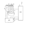
図1は、本発明によるアイドルストップ制御装置を使用するシステムの一例を示す図である。 FIG. 1 is a diagram showing an example of a system using an idle stop control device according to the present invention.
アイドルストップ制御装置1を適用できる内燃機関4は、エンジンコントロールモジュール(ECM)2と、バッテリ3と、スタータ5と、オルタネータ6と、を備える。
The internal combustion engine 4 to which the idle
ECM2は、中央演算装置(CPU)、読み出し専用メモリ(ROM)、ランダムアクセスメモリ(RAM)及び入出力インタフェース(I/Oインタフェース)を備えたマイクロコンピュータで構成される。そしてECM2は、各種センサからの信号を受けて、内燃機関4の運転状態を制御する。
The
バッテリ3は、内燃機関4を始動させるときにECM2やスタータ5に電力を供給する。また、バッテリ3は、オルタネータ6が発電した電気の一部を充電する。なお、アイドルストップ制御装置1は、バッテリ3内の液温を検出するバッテリ温度センサ7、バッテリ電圧を検出する電圧センサ8を備え、バッテリ温度センサ7の信号はECM2に読み込まれる。
The battery 3 supplies power to the
内燃機関4は、図1においては直列4気筒内燃機関となっているが、これに限られるわけではない。内燃機関4のクランク軸41は片端にクランクプーリ41Aが取り付けられる。クランクプーリ41A及びオルタネータ6にベルト42が架けられる。これによりクランク軸41の駆動力がベルト42を介してオルタネータ6に伝達される。
The internal combustion engine 4 is an in-line four-cylinder internal combustion engine in FIG. 1, but is not limited thereto. A
スタータ5は、バッテリ3の電力によって機関始動時にクランク軸41をクランキングする。スタータ5は、運行開始時の初回始動時には運転者のイグニッションスイッチ操作により作動開始する。なお、運転者がイグニッションスイッチをONにしてからOFFにするまでを一つの運行とする。つまり、途中でアイドルストップ制御による停止・再始動があっても、運転者がイグニッションスイッチ操作で内燃機関4を停止するまでは、一つの運行である。
The
また、アイドルストップ中に再始動する場合には、後述する再始動条件の成立を検知したECM2からの信号により作動開始する。一方、作動開始したスタータ5は、運転者の操作による作動またはアイドルストップ中の作動のいずれであっても、予め設定した条件が成立したら停止する。停止する条件は、例えば、機関回転速度が完爆回転速度を超えたこと、または作動開始から一定時間が経過したこと、等である。
Further, when restarting during idle stop, the operation is started by a signal from the
オルタネータ6は、内燃機関運転中にクランク軸41の駆動力によって発電し、電装負荷に電力供給する。そしてオルタネータ6の発電余剰分はバッテリ3に充電される。一方、オルタネータ6の発電量が不足するときは、バッテリ3が電力供給を補う。
The alternator 6 generates power by the driving force of the
なお、オルタネータ6をモータとしても作動し得るモータジェネレータとし、機関始動時にベルト42を介してオルタネータ6の駆動力をクランク軸41に伝達することでクランキングするようにしてもよい。
Alternatively, the alternator 6 may be a motor generator that can operate as a motor, and cranking may be performed by transmitting the driving force of the alternator 6 to the
次に、具体的なアイドルストップ制御ロジックについてフローチャートに沿って説明する。 Next, specific idle stop control logic will be described with reference to a flowchart.
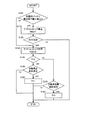
図2は、本実施形態に係るアイドルストップ制御ルーチンを説明するフローチャートである。なおアイドルストップ制御装置1は、この処理を微少時間(たとえば10ミリ秒)サイクルで繰り返し実行する。
FIG. 2 is a flowchart illustrating an idle stop control routine according to the present embodiment. The idle
本制御ルーチンでは、ECM2は機関始動に伴い降下するバッテリ電圧の最小値に基づいて、アイドルストップの禁止・許可を決定する。また、ECM2はバッテリ充電量に基づいてアイドルストップの禁止を解除するか否かを決定する。以下、フローチャートのステップにしたがって説明する。
In this control routine, the
ステップS100で、ECM2は、直近の機関始動時における始動時バッテリ電圧降下最小値が、予め設定したバッテリ出力低下判定値A以下であるか否かを判定する。具体的には、スタータ5の作動開始から作動停止までのバッテリ電圧をモニタしておき、その期間中の最小値を読み込んでバッテリ出力低下判定値Aとを比較する。
In step S100, the
この判定は、仮にアイドルストップを実行したら再始動可能か否かを判定するものである。始動時バッテリ電圧降下最小値とは、スタータ5が作動開始してから停止するまでのバッテリ電圧の最小値である。
This determination is to determine whether or not restarting is possible if idle stop is executed. The minimum battery voltage drop at start-up is the minimum battery voltage from when the
バッテリ出力低下判定値Aとは、バッテリ3の出力が、機関始動後にアイドルストップを実行したら再始動が不可能な程度まで低下しているか否かを判定する為の閾値である。バッテリ電圧はスタータ5の作動開始に伴って急激に降下し、その後エンジン回転速度の上昇に伴って徐々に回復する特性がある。そして、バッテリ3の劣化や充電不足等でバッテリ出力が低下するほど、始動時バッテリ電圧降下最小値が低くなる。
The battery output decrease determination value A is a threshold value for determining whether or not the output of the battery 3 has decreased to such an extent that it cannot be restarted when an idle stop is executed after the engine is started. The battery voltage has a characteristic that it rapidly decreases as the
そこで、機関始動後にアイドルストップからの再始動が可能な状態のバッテリ3の、始動時バッテリ電圧降下最小値をバッテリ出力低下判定値Aとして設定する。 Therefore, the minimum battery voltage drop at start-up of the battery 3 that can be restarted from the idle stop after the engine is started is set as the battery output decrease determination value A.
ECM2は、始動時バッテリ電圧降下最小値がバッテリ出力低下判定値A以下の場合はステップS110でアイドルストップを禁止してアイドルストップ禁止フラグFNGを1にし、バッテリ出力低下判定値Aより大きい場合はステップS130の処理を実行する。
The
なお、モニタしているバッテリ電圧をバッテリ出力低下判定値Aと逐次比較し、バッテリ出力低下判定値A以下となったらステップS110の処理を実行するようにしてもよい。また、ステップS100で用いた始動時バッテリ電圧降下最小値は、次回始動時まで保存する。つまり、次回始動時までステップS100の判定結果は同じになる。 Note that the battery voltage being monitored may be sequentially compared with the battery output decrease determination value A, and when the battery output decrease determination value A is less than or equal to, the process of step S110 may be executed. Further, the minimum battery voltage drop at start-up used in step S100 is stored until the next start-up. That is, the determination result in step S100 is the same until the next start.
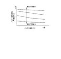
ステップS120で、ECM2は、バッテリ充電量SOCが予め設定したバッテリ充電状態判定値B以上であるか否かを判定する。バッテリ充電状態判定値Bとは、アイドルストップを実行しても内燃機関4を再始動するのに十分なバッテリ出力を発生し得る充電状態を示す値である。バッテリ充電状態判定値Bは、始動時バッテリ電圧降下最小値及びバッテリ温度に基づいて、例えば図5のマップを参照して設定する。図5はバッテリ充電状態判定値Bの設定に用いるマップの一例を示しており、横軸はバッテリ温度、縦軸はバッテリ充電状態判定値Bである。図中の各実線は、始動時バッテリ電圧降下最小値毎のバッテリ充電状態判定値Bを示している。
In step S120, the
図5に示すように、バッテリ充電状態判定値Bは、始動時バッテリ電圧降下最小値が小さいほど小さく、また、バッテリ温度が高いほど小さく設定する。 As shown in FIG. 5, the battery charge state determination value B is set to be smaller as the starting battery voltage drop minimum value is smaller, and smaller as the battery temperature is higher.
バッテリ充電量SOCがバッテリ充電状態判定値B以上の場合は、ECM2はステップS130の処理を実行する。バッテリ充電量SOCがバッテリ充電状態判定値Bより小さい場合は、ECM2は処理を終了する。
If the battery charge amount SOC is equal to or greater than the battery charge state determination value B, the
ステップS130で、ECM2はアイドルストップを許可し、アイドルストップ禁止フラグFNGをゼロにする。なお、既にアイドルストップが禁止されている場合には、アイドルストップの禁止を解除する。
In step S130, the
ステップS140で、ECM2はアイドルストップフラグFがゼロか否かを判定する。アイドルストップフラグFがゼロの場合は、ステップS150の処理を実行する。アイドルストップフラグFが1の場合はステップS170の処理を実行する。
In step S140, the
ステップS150で、ECM2はアイドルストップ条件が成立しているか否かを判定する。アイドルストップ条件は、内燃機関4の回転速度がアイドル回転速度のまま一定時間経過したとき、内燃機関4の冷却水温度やバッテリ3の状態が所定状態であるとき、運転者がアクセルペダルをOFFにしているとき、等に成立する。
In step S150, the
アイドルストップ条件が成立していると判定した場合は、ECM2はステップS160でアイドルストップを実行し、かつアイドルストップフラグFを1にして処理を終了する。アイドルストップ条件が成立していないと判定した場合は、そのまま処理を終了する。
If it is determined that the idle stop condition is satisfied, the
一方、ステップS140でアイドルストップフラグFが1であった場合は、ECM2はステップS170で再始動条件が成立しているか否かを判定する。再始動条件は、イグニッションスイッチがONの状態で一定時間が経過した場合、アイドルストップ中に運転者がブレーキペダルを離したとき、等に成立する。再始動条件が成立していると判定した場合は、ECM2はステップS180で内燃機関4を再始動させ、かつアイドルストップフラグFをゼロにして処理を終了する。
On the other hand, if the idle stop flag F is 1 in step S140, the
上述したように、本制御ルーチンは、始動時の判定でアイドルストップが禁止された場合でも、その後に内燃機関4を再始動可能な状態になったら、アイドルストップの禁止を解除するものである。 As described above, this control routine releases the prohibition of idling stop when the internal combustion engine 4 can be restarted after that even when idling stop is prohibited by the determination at the time of starting.
ところで、始動時バッテリ電圧最小値がバッテリ出力低下判定値A以下である場合、その原因がバッテリ3の劣化であれば、その後の走行中に回復することはない。しかし、単にバッテリの充電不足である場合には、走行中の充電により回復する可能性がある。そして本制御ルーチンによれば、単なる充電不足が原因のバッテリ出力低下によってアイドルストップが禁止された場合には、走行中にバッテリ出力が回復すればアイドルストップ禁止は解除される。その結果、アイドルストップの頻度を不要に低下させることを防止できる。 By the way, when the minimum battery voltage at start-up is equal to or less than the battery output decrease determination value A, if the cause is deterioration of the battery 3, it will not be recovered during the subsequent travel. However, if the battery is simply insufficiently charged, there is a possibility that the battery will recover due to charging during traveling. According to this control routine, when the idle stop is prohibited due to a decrease in the battery output due to the mere shortage of charge, the idle stop prohibition is canceled if the battery output is recovered during traveling. As a result, it is possible to prevent the frequency of idle stops from being lowered unnecessarily.
次に、本実施形態の制御を実行した場合のアイドルストップ制御装置1の実際の作動及びその効果について説明する。
Next, the actual operation and effect of the idle
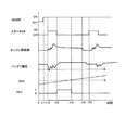
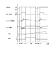
図3は、図2の制御ルーチンを実行した場合のタイムチャートである。図4は比較例のタイムチャートであり、始動時の判定でアイドルストップが禁止されると当該運行終了までアイドルストップが禁止されたままになる場合について示している。 FIG. 3 is a time chart when the control routine of FIG. 2 is executed. FIG. 4 is a time chart of a comparative example, and shows a case where the idle stop remains prohibited until the operation ends when the idle stop is prohibited by the determination at the start.
図3では、タイミングt11でイグニッションスイッチがONになり、タイミングt12でスタータ5が作動して、内燃機関4が始動している。そして内燃機関4が完爆状態となったタイミングt13でスタータ5は停止している。このとき、始動時バッテリ電圧降下最小値がバッテリ出力低下判定値A以下になっているので、タイミングt13でアイドルストップが禁止されている。
In FIG. 3, the ignition switch is turned on at timing t11, the
その後、走行中にバッテリ充電量SOCが増大し、バッテリ充電状態判定値B以上になったタイミングt14でアイドルストップの禁止が解除されている。そして、アイドルストップ条件が成立したタイミングt15からアイドルストップを実行している。アイドルストップ中のタイミングt16で再始動条件が成立するとスタータ5が作動し、内燃機関4が再始動している。再始動時における始動時バッテリ電圧降下最小値はバッテリ出力低下判定値Aより大きいので、アイドルストップは禁止されていない。
Thereafter, the prohibition of the idle stop is canceled at the timing t14 when the battery charge SOC increases during traveling and becomes equal to or higher than the battery charge state determination value B. Then, the idle stop is executed from the timing t15 when the idle stop condition is satisfied. When the restart condition is satisfied at the timing t16 during idling stop, the
上記のように、タイミングt14でアイドルストップの禁止が解除されているので、仮にタイミングt14からタイミングt15の間でアイドルストップ条件が成立したとしても、アイドルストップを実行できる。 As described above, since the prohibition of the idle stop is released at the timing t14, the idle stop can be executed even if the idle stop condition is satisfied between the timing t14 and the timing t15.
一方、図4に示した比較例も、タイミングt21−t23については図3のタイミングt11−t13と同様である。 On the other hand, in the comparative example shown in FIG. 4, the timing t21-t23 is the same as the timing t11-t13 in FIG.
しかし、タイミングt24でバッテリ充電量SOCがバッテリ充電状態判定値B以上になってもアイドルストップは禁止されたままである。その後、運転者がイグニッションスイッチをOFFにしたタイミングt25で、内燃機関4が停止してアイドルストップの禁止が解除される。そして、タイミングt26で再びイグニッションスイッチがONになり、タイミングt27でスタータ5が作動して、内燃機関4が再始動している。再始動時における始動時バッテリ電圧降下最小値はバッテリ出力低下判定値A以上なので、アイドルストップは禁止されない。
However, even when the battery charge amount SOC becomes equal to or higher than the battery charge state determination value B at the timing t24, the idle stop remains prohibited. Thereafter, at timing t25 when the driver turns off the ignition switch, the internal combustion engine 4 stops and the prohibition of idle stop is released. Then, the ignition switch is turned ON again at timing t26, the
このように、タイミングt23でアイドルストップが禁止されると、その後の走行中にアイドルストップ可能な状態に回復したとしても、当該運行が終了するタイミングt25までアイドルストップは禁止されたままとなる。したがって、仮にタイミングt24以降にアイドルストップ条件が成立しても、アイドルストップは実行されない。 As described above, when the idle stop is prohibited at the timing t23, the idle stop remains prohibited until the timing t25 at which the operation ends even if the idle recovery is enabled during the subsequent travel. Therefore, even if the idle stop condition is satisfied after timing t24, the idle stop is not executed.
上述したように、本実施形態によれば、アイドルストップを実行可能な状態になったらアイドルストップの禁止を解除するので、単なる充電不足等でアイドルストップが禁止された場合には、充電量が回復すればアイドルストップを実行することができる。また、バッテリ3の劣化によりバッテリ出力が低下している場合には、アイドルストップの禁止は解除されないので、再始動不能になることを防止できる。その結果、アイドルストップの頻度の低下を抑制し、燃費性能の向上を図ることができる。 As described above, according to the present embodiment, when the idle stop can be executed, the prohibition of the idle stop is canceled. Therefore, when the idle stop is prohibited due to insufficient charging or the like, the charge amount is recovered. Then, idle stop can be executed. Further, when the battery output is reduced due to the deterioration of the battery 3, the prohibition of idling stop is not canceled, so that it is possible to prevent the restart from being disabled. As a result, it is possible to suppress a decrease in the frequency of idle stops and improve fuel efficiency.
これに対して比較例の場合には、バッテリ出力低下の原因がバッテリの劣化か単なる充電不足かによらず、アイドルストップを禁止したらその運行中はアイドルストップの禁止は解除されない。したがって、実際にはアイドルストップを実行可能な状態であってもアイドルストップが禁止される状況が生じる。その結果、アイドルストップの頻度が低下して、燃費性能向上の効果が抑制されるおそれがある。 On the other hand, in the case of the comparative example, regardless of whether the battery output is reduced due to deterioration of the battery or simply insufficient charging, if the idle stop is prohibited, the prohibition of the idle stop is not canceled during the operation. Therefore, there is a situation where the idle stop is prohibited even in a state where the idle stop can be actually executed. As a result, the frequency of idling stops may be reduced, and the effect of improving fuel efficiency may be suppressed.
また、本制御ルーチンでは、始動時バッテリ電圧降下最小値が大きいほどバッテリ充電状態判定値Bを小さい値に設定する。これにより、始動時バッテリ電圧降下最小値とバッテリ出力低下判定値Aとの差が小さいほど、アイドルストップの禁止を解除するまでに必要なバッテリ充電量SOCが小さくなる。したがって、アイドルストップの禁止が解除されるまでに要する時間を、バッテリ3の状態に応じて短縮することができる。その結果、アイドルストップ実行の頻度を確保して、燃費性能の向上を図ることができる。 Further, in this control routine, the battery charge state determination value B is set to a smaller value as the starting battery voltage drop minimum value is larger. As a result, the smaller the difference between the minimum battery voltage drop at start-up and the battery output decrease determination value A, the smaller the battery charge SOC required before canceling the idle stop prohibition. Therefore, the time required until the prohibition of idle stop is canceled can be shortened according to the state of the battery 3. As a result, it is possible to ensure the frequency of idle stop execution and improve fuel efficiency.
さらに、本制御ルーチンでは、始動時バッテリ電圧降下最小値となるときのバッテリ温度が高いほど、バッテリ充電状態判定値Bを小さい値に設定する。これは、バッテリ充電量SOCが同じでも、バッテリ温度が高い方がより高いバッテリ出力を発生できるという特性に基づく。これによっても、アイドルストップの禁止を解除するまでに要する時間を短縮することができる。その結果、アイドルストップ実行の頻度を確保して、燃費性能の向上を図ることができる。 Further, in this control routine, the battery charge state determination value B is set to a smaller value as the battery temperature at the start-up battery voltage drop minimum value is higher. This is based on the characteristic that even if the battery charge amount SOC is the same, a higher battery output can generate a higher battery output. This also shortens the time required to release the idle stop prohibition. As a result, it is possible to ensure the frequency of idle stop execution and improve fuel efficiency.
上述した本実施形態による効果をまとめると、次のようになる。 The effects of the above-described embodiment can be summarized as follows.
その運行の初回始動時にバッテリ出力の低下によりアイドルストップが禁止されても、バッテリ充電量がバッテリ充電状態判定値B以上となった場合にアイドルストップの禁止を解除する禁止解除部(S130)とを備える。これにより、アイドルストップの頻度低下を抑制し、燃費性能の向上を図ることができる。 A prohibition canceling unit (S130) that cancels the prohibition of idle stop when the battery charge amount becomes equal to or higher than the battery charge state determination value B even if the idle stop is prohibited due to a decrease in battery output at the first start of the operation. Prepare. Thereby, it is possible to suppress a decrease in the frequency of idle stops and improve fuel efficiency.
また、始動時バッテリ電圧降下最小値が大きいほどバッテリ充電状態判定値Bを小さい値に設定するので、アイドルストップ禁止を解除するまでの期間を短くすることができる。これによりアイドルストップ実行の頻度を確保して燃費性能の向上を図ることができる。 In addition, since the battery charge state determination value B is set to a smaller value as the starting battery voltage drop minimum value is larger, the period until the idle stop prohibition is canceled can be shortened. As a result, the frequency of idle stop execution can be secured and the fuel efficiency can be improved.
また、バッテリ温度が高いほどバッテリ充電状態判定値Bを小さい値に設定するので、これによってもアイドルストップ禁止を解除するまでの期間を短くし、アイドルストップ実行の頻度を確保して燃費性能の向上を図ることができる。 In addition, since the battery charge state determination value B is set to a smaller value as the battery temperature is higher, this also shortens the period until the idle stop prohibition is canceled, ensuring the frequency of idle stop execution and improving fuel efficiency. Can be achieved.
なお、本発明は上記の実施の形態に限定されるわけではなく、特許請求の範囲に記載の技術的思想の範囲内で様々な変更を成し得ることは言うまでもない。 The present invention is not limited to the above-described embodiments, and it goes without saying that various modifications can be made within the scope of the technical idea described in the claims.
1 アイドルストップ制御装置
2 エンジンコントロールモジュール(ECM)
3 バッテリ
4 内燃機関
5 スタータ
6 オルタネータ
7 バッテリ温度センサ
8 電圧センサ
1 Idle
3 Battery 4
Claims (3)
その運行の初回始動時にバッテリ電圧に基づいてバッテリ出力の低下を判定するバッテリ出力低下判定部と、
バッテリ出力が低下していると判定したときにアイドルストップを禁止するアイドルストップ禁止部と、
バッテリ充電量が前記内燃機関の再始動に必要な出力を発生し得る充電量として予め設定した禁止解除用判定値以上となった場合に前記アイドルストップの禁止を解除する禁止解除部と、
を備えることを特徴とするアイドルストップ制御装置。 In an idle stop control device for executing an idle stop for stopping the internal combustion engine when the idle stop condition is satisfied, and restarting the internal combustion engine when the restart condition is satisfied during the idle stop,
A battery output decrease determination unit that determines a decrease in battery output based on the battery voltage at the first start of the operation;
An idle stop prohibiting unit that prohibits an idle stop when it is determined that the battery output is low;
A prohibition canceling unit for canceling the prohibition of the idle stop when the battery charge amount is equal to or higher than a prohibition determination value set in advance as a charge amount capable of generating an output necessary for restarting the internal combustion engine;
An idle stop control device comprising:
前記禁止解除部は、バッテリ温度が高いほど前記禁止解除用判定値を小さい値に設定する請求項1または2に記載のアイドルストップ制御装置。 Battery temperature detection means for detecting the liquid temperature of the battery,
The idle stop control device according to claim 1, wherein the prohibition canceling unit sets the prohibition canceling determination value to a smaller value as the battery temperature is higher.
Priority Applications (1)
| Application Number | Priority Date | Filing Date | Title |
|---|---|---|---|
| JP2011120415A JP2012246867A (en) | 2011-05-30 | 2011-05-30 | Idling stop control device |
Applications Claiming Priority (1)
| Application Number | Priority Date | Filing Date | Title |
|---|---|---|---|
| JP2011120415A JP2012246867A (en) | 2011-05-30 | 2011-05-30 | Idling stop control device |
Publications (1)
| Publication Number | Publication Date |
|---|---|
| JP2012246867A true JP2012246867A (en) | 2012-12-13 |
Family
ID=47467540
Family Applications (1)
| Application Number | Title | Priority Date | Filing Date |
|---|---|---|---|
| JP2011120415A Withdrawn JP2012246867A (en) | 2011-05-30 | 2011-05-30 | Idling stop control device |
Country Status (1)
| Country | Link |
|---|---|
| JP (1) | JP2012246867A (en) |
Cited By (6)
| Publication number | Priority date | Publication date | Assignee | Title |
|---|---|---|---|---|
| US20150178997A1 (en) * | 2013-12-25 | 2015-06-25 | Denso Corporation | Vehicle diagnosis system and method |
| JP2015190451A (en) * | 2014-03-28 | 2015-11-02 | トヨタ自動車株式会社 | Vehicle control device |
| JP2018204571A (en) * | 2017-06-07 | 2018-12-27 | スズキ株式会社 | Idle stop vehicle |
| CN111824052A (en) * | 2019-04-16 | 2020-10-27 | 丰田自动车株式会社 | Controls for the drive system |
| US11279357B2 (en) | 2013-12-25 | 2022-03-22 | Denso Corporation | Vehicle diagnosis system and method |
| JP2023127843A (en) * | 2022-03-02 | 2023-09-14 | スズキ株式会社 | Vehicle control device |
-
2011
- 2011-05-30 JP JP2011120415A patent/JP2012246867A/en not_active Withdrawn
Cited By (13)
| Publication number | Priority date | Publication date | Assignee | Title |
|---|---|---|---|---|
| US11279357B2 (en) | 2013-12-25 | 2022-03-22 | Denso Corporation | Vehicle diagnosis system and method |
| US9677529B2 (en) * | 2013-12-25 | 2017-06-13 | Denso Corporation | Vehicle diagnosis system and method |
| US10351127B2 (en) | 2013-12-25 | 2019-07-16 | Denso Corporation | Vehicle diagnosis system and method |
| US10371074B2 (en) | 2013-12-25 | 2019-08-06 | Denso Corporation | Vehicle diagnosis system and method |
| US20150178997A1 (en) * | 2013-12-25 | 2015-06-25 | Denso Corporation | Vehicle diagnosis system and method |
| JP2015190451A (en) * | 2014-03-28 | 2015-11-02 | トヨタ自動車株式会社 | Vehicle control device |
| JP2018204571A (en) * | 2017-06-07 | 2018-12-27 | スズキ株式会社 | Idle stop vehicle |
| CN111824052A (en) * | 2019-04-16 | 2020-10-27 | 丰田自动车株式会社 | Controls for the drive system |
| JP2020176530A (en) * | 2019-04-16 | 2020-10-29 | トヨタ自動車株式会社 | Drive system controller |
| JP7156150B2 (en) | 2019-04-16 | 2022-10-19 | トヨタ自動車株式会社 | Drive system controller |
| CN111824052B (en) * | 2019-04-16 | 2024-05-28 | 丰田自动车株式会社 | Drive system control device |
| JP2023127843A (en) * | 2022-03-02 | 2023-09-14 | スズキ株式会社 | Vehicle control device |
| JP7782318B2 (en) | 2022-03-02 | 2025-12-09 | スズキ株式会社 | Vehicle control device |
Similar Documents
| Publication | Publication Date | Title |
|---|---|---|
| JP5035431B2 (en) | Vehicle control system | |
| JP5212391B2 (en) | Idle stop control device | |
| CN104838560B (en) | Battery charge controller, charge control method | |
| CN103026036B (en) | Automatic stop device and automatic stop method of internal combustion engine | |
| JP2012246867A (en) | Idling stop control device | |
| JP6446886B2 (en) | Motor control device | |
| JP2014194184A (en) | Control device of idle stop vehicle | |
| JP2021127096A (en) | Vehicle control device | |
| WO2012091079A1 (en) | Control device of vehicle | |
| JP5850173B2 (en) | Alternator control device | |
| EP3499010B1 (en) | Method and device for controlling vehicle including idle stop and go function | |
| JPWO2014057576A1 (en) | Engine automatic stop / restart device and engine automatic stop / restart method | |
| JP6356591B2 (en) | Battery monitoring device | |
| JP6610470B2 (en) | Engine starter | |
| JP2010112354A (en) | Controller of vehicle internal combustion engine | |
| JP4815942B2 (en) | Control device for internal combustion engine | |
| JP2018115568A (en) | Engine control device | |
| JP5808298B2 (en) | Battery state determination device for internal combustion engine | |
| JP6682383B2 (en) | Vehicle control device | |
| JP5110231B2 (en) | Starter control device, engine starter, and vehicle | |
| JP6891486B2 (en) | Hybrid vehicle drive controller | |
| JP2013164016A (en) | Vehicle control device | |
| JP2004308579A (en) | Idle stop device | |
| JP5852932B2 (en) | Engine restart control device | |
| JP6851743B2 (en) | Jumping start judgment device |
Legal Events
| Date | Code | Title | Description |
|---|---|---|---|
| A300 | Withdrawal of application because of no request for examination |
Free format text: JAPANESE INTERMEDIATE CODE: A300 Effective date: 20140805 |