JP2012247207A - Electron beam irradiation system and conveyance system - Google Patents
Electron beam irradiation system and conveyance system Download PDFInfo
- Publication number
- JP2012247207A JP2012247207A JP2011116816A JP2011116816A JP2012247207A JP 2012247207 A JP2012247207 A JP 2012247207A JP 2011116816 A JP2011116816 A JP 2011116816A JP 2011116816 A JP2011116816 A JP 2011116816A JP 2012247207 A JP2012247207 A JP 2012247207A
- Authority
- JP
- Japan
- Prior art keywords
- transport
- irradiated
- electron beam
- conveyance
- transport device
- Prior art date
- Legal status (The legal status is an assumption and is not a legal conclusion. Google has not performed a legal analysis and makes no representation as to the accuracy of the status listed.)
- Pending
Links
- 238000010894 electron beam technology Methods 0.000 title claims abstract description 112
- 238000011144 upstream manufacturing Methods 0.000 claims abstract description 7
- 230000032258 transport Effects 0.000 claims description 267
- 238000012546 transfer Methods 0.000 claims description 25
- 230000001678 irradiating effect Effects 0.000 claims description 3
- 230000007246 mechanism Effects 0.000 description 12
- 230000001133 acceleration Effects 0.000 description 6
- 238000000605 extraction Methods 0.000 description 6
- 238000000034 method Methods 0.000 description 6
- 238000010586 diagram Methods 0.000 description 4
- 230000005684 electric field Effects 0.000 description 3
- 239000000463 material Substances 0.000 description 3
- 230000008569 process Effects 0.000 description 3
- 238000012545 processing Methods 0.000 description 3
- 230000009467 reduction Effects 0.000 description 3
- 229910001220 stainless steel Inorganic materials 0.000 description 3
- 239000010935 stainless steel Substances 0.000 description 3
- 230000006835 compression Effects 0.000 description 2
- 238000007906 compression Methods 0.000 description 2
- 230000003028 elevating effect Effects 0.000 description 2
- 238000007726 management method Methods 0.000 description 2
- 230000001954 sterilising effect Effects 0.000 description 2
- 238000004659 sterilization and disinfection Methods 0.000 description 2
- 230000001360 synchronised effect Effects 0.000 description 2
- 239000010936 titanium Substances 0.000 description 2
- 108010083687 Ion Pumps Proteins 0.000 description 1
- 229910018503 SF6 Inorganic materials 0.000 description 1
- RTAQQCXQSZGOHL-UHFFFAOYSA-N Titanium Chemical compound [Ti] RTAQQCXQSZGOHL-UHFFFAOYSA-N 0.000 description 1
- 238000013459 approach Methods 0.000 description 1
- 230000005540 biological transmission Effects 0.000 description 1
- 201000011510 cancer Diseases 0.000 description 1
- 239000000919 ceramic Substances 0.000 description 1
- 230000008859 change Effects 0.000 description 1
- 238000004132 cross linking Methods 0.000 description 1
- 239000006185 dispersion Substances 0.000 description 1
- 239000011888 foil Substances 0.000 description 1
- 235000013305 food Nutrition 0.000 description 1
- 230000003902 lesion Effects 0.000 description 1
- 238000012986 modification Methods 0.000 description 1
- 230000004048 modification Effects 0.000 description 1
- 230000005855 radiation Effects 0.000 description 1
- 229920005989 resin Polymers 0.000 description 1
- 239000011347 resin Substances 0.000 description 1
- 239000004065 semiconductor Substances 0.000 description 1
- SFZCNBIFKDRMGX-UHFFFAOYSA-N sulfur hexafluoride Chemical compound FS(F)(F)(F)(F)F SFZCNBIFKDRMGX-UHFFFAOYSA-N 0.000 description 1
- 229960000909 sulfur hexafluoride Drugs 0.000 description 1
- 229910052719 titanium Inorganic materials 0.000 description 1
Images




Landscapes
- Physical Or Chemical Processes And Apparatus (AREA)
Abstract
Description
本発明は、被照射物に電子線を照射する電子線照射システムおよび搬送システムに関する。 The present invention relates to an electron beam irradiation system and a transport system for irradiating an object with an electron beam.
従来、医療器具や食品等の滅菌、樹脂の架橋や硬化、悪性腫瘍等の病巣の除去等、様々な分野で利用されている電子線照射装置(例えば、特許文献1、2)が知られている。このような電子線照射装置は、カソード電極と加速器を備えており、カソード電極に電力を供給することでカソード電極から電子線を放出し、その電子線を加速器で加速して被照射物に照射する。電子線照射装置を利用して被照射物に電子線を照射する場合、被照射物は、コンベア等の搬送装置で、被照射物に電子線が照射される領域(照射領域)に、連続的に搬送されることが多い。 Conventionally, electron beam irradiation apparatuses (for example, Patent Documents 1 and 2) used in various fields such as sterilization of medical instruments and foods, cross-linking and curing of resins, and removal of lesions such as malignant tumors are known. Yes. Such an electron beam irradiation apparatus is equipped with a cathode electrode and an accelerator. By supplying electric power to the cathode electrode, the electron beam is emitted from the cathode electrode, and the electron beam is accelerated by the accelerator to irradiate the irradiated object. To do. When irradiating an irradiation object with an electron beam using an electron beam irradiation apparatus, the irradiation object is continuously conveyed to an area (irradiation area) where the irradiation object is irradiated with an electron beam by a transport device such as a conveyor. Often transported to
図8は、従来の搬送装置20を説明するための説明図である。電子線照射装置10は、電子線を加速して放出し、照射領域Rにおいてその電子線を被照射物Wに照射する。ここで、被照射物Wは、搬送装置20を構成するコンベア22等に載置されて照射領域Rに搬送される。このとき、被照射物Wは、前後の被照射物Wと一定間隔S分、離隔されてコンベア22上に載置される。そうすると、被照射物Wと被照射物Wとの間は、被照射物Wに電子線が照射されず、コンベア22に電子線が照射されることとなり、電子線が無駄に消費されてしまう。
FIG. 8 is an explanatory diagram for explaining a
そこで、照射領域Rに被照射物Wを搬送する第1搬送装置と、第1搬送装置よりも被照射物Wの搬送方向上流側に設置され、被照射物Wを搬送するとともに、第1搬送装置に被照射物Wを搬出する第2搬送装置とを備えておき、第1搬送装置の搬送速度を、第2搬送装置の搬送速度よりも遅くすることで、第1搬送装置において、被照射物Wを密接搬送する技術が開示されている(例えば、特許文献3)。 Therefore, the first transport device that transports the irradiated object W to the irradiation region R and the upstream side of the first transport device in the transport direction of the irradiated object W transport the irradiated object W and the first transport device. The apparatus is provided with a second transport device that carries the irradiated object W out, and the transport speed of the first transport device is slower than the transport speed of the second transport device, so that the first transport device is irradiated A technique for closely conveying an object W is disclosed (for example, Patent Document 3).
上述した特許文献3の技術では、照射領域Rにおいて、被照射物Wが前後の被照射物Wと密接して搬送されるので、電子線の無駄な照射を低減することができる。しかし、被照射物Wの長さや、被照射物Wの滅菌に必要な照射時間は、被照射物Wごとに異なる。したがって、特許文献3の技術を利用して、照射領域Rにおいて適切に被照射物W同士を密接させるためには、被照射物Wに応じて、第1搬送装置および第2搬送装置の搬送速度をユーザが手入力で適宜変更しなければならず、ユーザに煩雑な作業を強いることになっていた。 In the technique of Patent Document 3 described above, since the irradiated object W is conveyed in close contact with the preceding and following irradiated objects W in the irradiation region R, it is possible to reduce unnecessary irradiation of electron beams. However, the length of the irradiation object W and the irradiation time necessary for sterilization of the irradiation object W are different for each irradiation object W. Therefore, in order to appropriately bring the irradiated objects W into close contact with each other in the irradiation region R using the technique of Patent Document 3, the transfer speeds of the first transfer device and the second transfer device according to the irradiated object W. Therefore, the user has to change manually as necessary, and the user is forced to perform complicated work.
ここで、被照射物Wを搬送装置上に載置する際に、予め被照射物W同士を密接させておくことも考えられる。しかし、電子線の照射によって放出される放射線の漏洩を防ぐために、被照射物Wを搬送する搬送装置は、建屋内において複雑な搬送経路をとらなければならず、また、被照射物Wの搬送距離も長くなってしまう。そのため、搬送途中で被照射物Wが詰まってしまい、正常な搬送が行えなくなってしまったり、被照射物Wのカウントの精度が保てず、個数管理ができなくなってしまったりするおそれもある。 Here, it is also conceivable that the objects to be irradiated W are brought into close contact with each other when the objects to be irradiated W are placed on the transport device. However, in order to prevent leakage of radiation emitted by electron beam irradiation, the transport device that transports the object to be irradiated W has to take a complicated transport path in the building, and also transports the object to be irradiated W. The distance will be longer. For this reason, the irradiated object W may be clogged in the middle of conveyance, and normal conveyance may not be performed, or the number of irradiated objects W may not be accurately counted, and the number management may not be performed.
そこで本発明は、このような課題に鑑み、被照射物に応じて、第1搬送装置、第2搬送装置、および、第2搬送装置に被照射物を送出する送出部を工夫することで、ユーザに煩雑な作業を強いることなく、電子線の照射領域において、確実に被照射物同士を密接させて搬送することが可能な電子線照射システムおよび搬送システムを提供することを目的としている。 Therefore, in view of such a problem, the present invention devised a first transport device, a second transport device, and a delivery unit that sends the irradiated material to the second transport device according to the irradiated object, An object of the present invention is to provide an electron beam irradiation system and a conveyance system that can reliably convey objects to be irradiated in close contact with each other in an electron beam irradiation region without forcing a user to perform complicated operations.
上記課題を解決するために、本発明の電子線照射システムは、被照射物に電子線を照射する電子線照射装置と、被照射物を搬送するとともに、電子線照射装置によって被照射物に電子線が照射される領域である照射領域に被照射物を通過させる第1搬送装置と、第1搬送装置よりも被照射物の搬送方向上流側に設けられ、第1搬送装置の搬送速度よりも速い搬送速度で被照射物を搬送するとともに、第1搬送装置に被照射物を搬出する第2搬送装置と、第2搬送装置に被照射物を送出する送出部と、被照射物に応じて、第1搬送装置の搬送速度、第2搬送装置の搬送速度、および、送出部の送出間隔を制御する制御装置と、を備えたことを特徴とする。 In order to solve the above problems, an electron beam irradiation system according to the present invention includes an electron beam irradiation device that irradiates an irradiation object with an electron beam, and an object to be irradiated by the electron beam irradiation device. A first transport device that passes an irradiated object through an irradiation region that is an area irradiated with a line, and an upstream side of the first transport device in the transport direction of the irradiated object, the transport speed of the first transport device Depending on the object to be irradiated, the second conveying apparatus that conveys the object to be irradiated to the first conveying apparatus, the sending unit that sends the object to the second conveying apparatus, And a control device for controlling the transport speed of the first transport device, the transport speed of the second transport device, and the delivery interval of the delivery section.
制御装置は、第1搬送装置の搬送速度と、第2搬送装置の搬送速度とを所定の比率に維持してもよい。 The control device may maintain the transport speed of the first transport device and the transport speed of the second transport device at a predetermined ratio.
第1搬送装置は、被照射物を搬送する第1搬送体を含んで構成され、第2搬送装置は、被照射物を搬送する第2搬送体を含んで構成され、第1搬送体および第2搬送体は、制御装置によって回転数が制御される1つのモータに連結され、制御装置は1つのモータを回転させることにより、第1搬送装置の搬送速度と、第2搬送装置の搬送速度とを異ならせてもよい。 The first transport device includes a first transport body that transports the object to be irradiated, and the second transport device includes a second transport body that transports the object to be irradiated, and includes the first transport body and the first transport body. The two transport bodies are connected to one motor whose rotational speed is controlled by the control device, and the control device rotates one motor to thereby transport the first transport device, the second transport device, and the second transport device. May be different.
上記課題を解決するために、本発明の搬送システムは、被照射物に電子線を照射する電子線照射装置に、被照射物を搬送する搬送システムであって、被照射物を搬送するとともに、電子線照射装置によって被照射物に電子線が照射される領域である照射領域に被照射物を通過させる第1搬送装置と、第1搬送装置よりも被照射物の搬送方向上流側に設けられ、第1搬送装置の搬送速度よりも速い搬送速度で被照射物を搬送するとともに、第1搬送装置に被照射物を搬出する第2搬送装置と、第2搬送装置に被照射物を送出する送出部と、被照射物に応じて、第1搬送装置の搬送速度、第2搬送装置の搬送速度、および、送出部の送出間隔を制御する制御装置と、を備えたことを特徴とする。 In order to solve the above problems, the transport system of the present invention is a transport system that transports an object to be irradiated to an electron beam irradiation apparatus that irradiates the object with an electron beam, and transports the object to be irradiated, A first transport device that passes the irradiated object through an irradiation region that is an area where the electron beam is irradiated onto the irradiated object by the electron beam irradiation device; and an upstream side of the first transport device in the transport direction of the irradiated object. The object to be irradiated is transported at a transport speed faster than the transport speed of the first transport apparatus, the second transport apparatus for unloading the object to be transported to the first transport apparatus, and the object to be irradiated to the second transport apparatus. A delivery unit and a control device for controlling the delivery speed of the first delivery device, the delivery speed of the second delivery device, and the delivery interval of the delivery unit according to the object to be irradiated are provided.
本発明によれば、被照射物に応じて、第1搬送装置、第2搬送装置、および、第2搬送装置に被照射物を送出する送出部を工夫することで、ユーザに煩雑な作業を強いることなく、電子線の照射領域において、確実に被照射物同士を密接させて搬送することが可能となる。こうして、電子線の無駄な照射を低減することができる。 According to the present invention, depending on the object to be irradiated, the first transfer device, the second transfer device, and the sending unit for sending the irradiation object to the second transfer device can be devised, so that the user can perform complicated work. Without being forced, the irradiated objects can be reliably transported in the electron beam irradiation region. Thus, useless irradiation of electron beams can be reduced.
以下に添付図面を参照しながら、本発明の好適な実施形態について詳細に説明する。かかる実施形態に示す寸法、材料、その他具体的な数値等は、発明の理解を容易とするための例示にすぎず、特に断る場合を除き、本発明を限定するものではない。なお、本明細書及び図面において、実質的に同一の機能、構成を有する要素については、同一の符号を付することにより重複説明を省略し、また本発明に直接関係のない要素は図示を省略する。 Hereinafter, preferred embodiments of the present invention will be described in detail with reference to the accompanying drawings. The dimensions, materials, and other specific numerical values shown in the embodiments are merely examples for facilitating the understanding of the invention, and do not limit the present invention unless otherwise specified. In the present specification and drawings, elements having substantially the same function and configuration are denoted by the same reference numerals, and redundant description is omitted, and elements not directly related to the present invention are not illustrated. To do.
(電子線照射システム100)
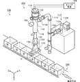
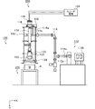
図1は、電子線照射システム100の外観斜視図であり、図2は、図1におけるZ軸方向から電子線照射システム100を見た図である。なお、図1では、理解を容易にするために電子線照射装置200を支持する支持機構を省略する。
(Electron beam irradiation system 100)
1 is an external perspective view of the electron
図1および図2に示すように、電子線照射システム100は、電子線照射装置200と、搬送システム300とを含んで構成される。
As shown in FIGS. 1 and 2, the electron
(電子線照射装置200)
電子線照射装置200は、カソード電源104と、電子銃110と、高周波ユニット112と、導波管114と、プリバンチャ116と、加速器118と、スキャンホーン120とを備えて構成されている。なお、電子銃110、プリバンチャ116、加速器118、スキャンホーン120は、内部空間(真空室)が連続しており、この内部空間は、イオンポンプ等の真空ポンプ102で高真空状態から超高真空状態(例えば、10E−5Pa以下)に維持される。
(Electron beam irradiation apparatus 200)
The electron
電子線照射装置200において、電子銃110から放出された熱電子は、プリバンチャ116、加速器118で加速され、スキャンホーン120を通過して、搬送システム300で搬送される被照射物Wに向かって図1中Y軸方向に照射される。以下、電子線照射装置200の各機能部について詳述する。
In the electron
(電子銃110)
電子銃110は、例えば、三極管電子銃であり、カソード電源(交流電源)104から供給された電力によってカソード電極を加熱し、パルス状に印加された高電圧のグリッド電圧(引出電圧)により、電子線を放出する。
(Electron gun 110)
The
(高周波ユニット112、導波管114)
高周波ユニット112は、クライストロン等で構成される高周波増幅器112aと、高周波増幅器112aに電力を供給する高周波電源(電力供給部)112bとを含んで構成され、導波管114を通じてプリバンチャ116および加速器118に、例えばSバンドに相当する3GHzのパルス状の高周波電力を供給する。導波管114は、セラミック等で構成されたRF窓114a、114bを通じて、高周波増幅器112aから増幅されて供給される高周波の電圧を加速器118に供給する。導波管114におけるRF窓114aとRF窓114bの間には、六フッ化硫黄(SF6)等の絶縁ガスが充填されており、高周波増幅器112aで増幅されて出力された電圧によって導波管114が放電してしまう事態を回避する。なおRF窓114a、114bはSF6と真空とを隔てる境界の役割を果たす。
(High-
The high-
(プリバンチャ116)
プリバンチャ116は、電子銃110と加速器118の間に設けられ、導波管114を通じて高周波ユニット112に接続されている。プリバンチャ116は、電子銃110から入射された電子線をバンチング(密度圧縮(速度変調))して、加速器118に送出する。具体的に説明すると、プリバンチャ116内は、高周波増幅器112aから供給された高周波の電圧によって高周波電界が形成されており、プリバンチャ116を通過した電子線は、バンチングされて加速器118に入射する。プリバンチャ116で電子線をバンチングすることにより、加速器118で加速された電子線のエネルギーの分散を小さくすることができ、電子線のエネルギーの均一性を向上させることが可能となる。
(Prebuncha 116)
The
ここで、プリバンチャ116によって圧縮された電子線の加速器118への入射タイミングが、加速器118における高周波の正位相と同期したときのみ、電子線は加速器118で効率よく加速される。したがって、プリバンチャ116から加速器118への電子線の入射タイミングを調整するために、プリバンチャ116の高周波導入部116aには、不図示の位相調整手段が設けられている。また、電子線の圧縮率(バンチングされた電子線の長さ)も加速器118による加速効率に影響するため、すなわち、電子線の長さが短い程、加速効率が向上する。したがって、供給する高周波の強度を調整して電子線の長さを調整するために、プリバンチャ116の高周波導入部116aには、不図示の減衰(アッテネータ)手段が設けられている。
Here, the electron beam is efficiently accelerated by the
(加速器118)
加速器118は、ステンレス(例えばSUS)等で形成され、内部に複数の加速空間を有して構成される。高周波増幅器112aから高周波の電圧(例えば、3GHz)が供給されると、加速器118の複数の加速空間が空間共振器として機能し、空間共振器内に時間的に変化する電界が生じる。そして、この時間的に変化する電界で、プリバンチャ116によって圧縮された電子線を加速する。
(Accelerator 118)
The
ここで、電子線の速度と加速空間における正に帯電する(正位相になる)タイミングが同期するように、高周波増幅器112aから供給される電圧の周波数と、加速空間の距離が設計されているため、電子線は加速器118内で徐々に加速され、最終的には、例えば10MeV程度まで加速されて、スキャンホーン120に入射される。
Here, the frequency of the voltage supplied from the high-
なお、ここでは、加速器118として、定在波型の線形(リニアック)加速器を採用しているが、電子を加速できればよく、進行波型の線形加速器や、シンクロトロン、サイクロトロン等の円形加速器を採用することもできる。
In this case, a standing wave type linear accelerator is used as the
(スキャンホーン120)
スキャンホーン120は、ステンレス(例えばSUS)等で形成され、その内部空間が加速器118と連結され、加速器118の出口付近に設けられたスキャン電磁石122と、加速器118と連結する端部と対向する端部に設けられた電子線取出部124とを含んで構成される。
(Scan horn 120)
The
スキャン電磁石122は、加速器118から入射された電子線を水平方向(図1中X軸方向)に走査(スキャン)する。電子線の進行方向は鉛直方向(図1中Y軸方向)であるため、スキャン電磁石122が鉛直方向に進行する電子線を水平方向に走査することにより、水平方向に幅のある被照射物Wに確実に電子線を照射することができる。
The
電子線取出部124は、例えば、50μm程度の厚みのチタン(Ti)箔で構成され、内部空間と、大気とを隔てる境界の役割を果たす。そして、電子線取出部124から大気雰囲気に放出された電子線は、被照射物Wに照射される。
The electron
こうして、電子銃110で放出された電子線は、加速器118で加速されて、電子線取出部124を通じて、被照射物Wに照射される。
In this way, the electron beam emitted by the
ところで、照射領域Rにおいて、被照射物Wが前後の被照射物Wと離隔して搬送される場合、被照射物Wと被照射物Wとの間に電子線が照射されてしまい電子線が無駄に消費されることになっていた。 By the way, in the irradiation region R, when the irradiated object W is transported away from the preceding and following irradiated objects W, an electron beam is irradiated between the irradiated object W and the irradiated object W, and the electron beam is generated. It was supposed to be consumed in vain.
以下、照射領域Rにおいて、被照射物W同士を密接させて搬送することで、電子線が無駄に消費される事態を回避することが可能な搬送システム300について詳述する。
Hereinafter, the
(搬送システム300)
図3は、搬送システム300を説明するための説明図であり、図1におけるY軸方向から搬送システム300を見た図である。図3に示すように、搬送システム300は、第1搬送装置310と、第2搬送装置320と、第3搬送装置330と、第4搬送装置340と、第5搬送装置350と、第6搬送装置360と、送出部370と、被照射物判定部380と、カウンタ382と、通過センサ384と、制御装置390とを含んで構成され、被照射物Wを照射領域Rに搬送したり、照射領域Rから被照射物Wを搬出したりすることで、照射領域Rに被照射物Wを通過させる。ここで、第1搬送装置310、第2搬送装置320、第3搬送装置330、第4搬送装置340、第5搬送装置350、第6搬送装置360は、例えば、コンベアで構成され、被照射物Wを載置した状態で搬送する。
(Conveyance system 300)
FIG. 3 is an explanatory diagram for explaining the
第1搬送装置310は、例えば、10〜200mm/secの搬送速度V1で被照射物Wを搬送するとともに、照射領域Rに被照射物Wを通過させる。第2搬送装置320は、第1搬送装置310よりも被照射物Wの搬送方向上流側に設けられ、被照射物Wを搬送するとともに、第1搬送装置310に被照射物Wを搬出する。本実施形態において、第2搬送装置320の搬送速度V2は、第1搬送装置310の搬送速度V1よりも速くなるように、後述する制御装置390によって制御される。また、制御装置390は、搬送速度V1と、搬送速度V2とを所定の比率に維持する。例えば、制御装置390は、搬送速度V2が、搬送速度V1の1.2倍になるように制御する。制御装置390による、搬送速度V1と、搬送速度V2とを所定の比率に維持する機構については、後に詳述する。
For example, the
第3搬送装置330は、第1搬送装置310よりも被照射物Wの搬送方向下流側に設けられ、第1搬送装置310から搬出された被照射物Wを搬送する。第4搬送装置340は、搬入口から搬入された被照射物Wを搬送するとともに、後述する送出部370に被照射物Wを搬出する。第5搬送装置350は、第3搬送装置330から搬出された被照射物Wを搬送するとともに、被照射物Wを第6搬送装置360に搬出する。第6搬送装置360は、第5搬送装置350から搬出された被照射物Wを搬送するとともに搬出口へ被照射物Wを搬出する。本実施形態において、第3搬送装置330の搬送速度V3、第4搬送装置340の搬送速度V4、第5搬送装置350の搬送速度V5、第6搬送装置360の搬送速度V6は、搬送速度V2と実質的に等しい、または、搬送速度V1よりも十分大きな速度で固定されている。また、第4搬送装置340は、通過センサ384によって検出される被照射物Wの有無によって、停止したり、稼働したりするように、制御装置390に制御される。
The
送出部370は、例えばプッシャーで構成され、第4搬送装置340から搬出された被照射物Wを第2搬送装置320に送出(押出)する。被照射物判定部380は、搬送方向における被照射物Wの長さL0を検出する。カウンタ382は、第3搬送装置330に搬送される被照射物Wをカウントする。すなわちカウンタ382は、照射領域Rを通過し、照射領域Rにおいて電子線で滅菌された被照射物Wの個数をカウントする。
The sending
制御装置390は、中央処理装置(CPU)、プログラム等が格納されたROM、ワークエリアとしてのRAM等を含む半導体集積回路により、搬送システム300全体を管理および制御する。ここで、制御装置390は、第1搬送装置310の搬送速度V1、第2搬送装置320の搬送速度V2、送出部370の送出間隔PTを制御する。
The
具体的に説明すると、制御装置390は、まず、電子線照射装置200によって放出される電子線の出力(例えば、10MeV、500pps)と、被照射物Wに必要な照射量と、被照射物判定部380が検出した被照射物Wの長さL0とに基づいて、搬送速度V1を決定する。続いて、制御装置390は、被照射物判定部380が検出した被照射物Wの長さL0に応じて、第1搬送装置310において被照射物Wが密接して搬送されるように、送出間隔PTを算出する。
More specifically, the
図4は、制御装置390による送出間隔PTの算出処理を説明するための説明図である。図4(a)に示す時刻t1において、被照射物W1が第2搬送装置320から第1搬送装置310に載置され始めてから、図4(b)に示す時刻t2において、被照射物W1が第2搬送装置320から第1搬送装置310へ搬出され、図4(c)に示す時刻t3において、被照射物W1が第2搬送装置320から第1搬送装置310に載置され終わるまでに、L0/V1secかかることになる。すなわち、時刻t1から時刻t3までは、L0/V1secである。
FIG. 4 is an explanatory diagram for explaining the calculation process of the sending interval PT by the
そして、時刻t3において、被照射物W1が第2搬送装置320から第1搬送装置310に載置され終わってすぐに、被照射物W1の次に照射領域Rに搬送される被照射物W2が、第2搬送装置320から第1搬送装置310に載置され始めるようにすれば、第1搬送装置310において被照射物W1と被照射物W2とを密接させて搬送することができる。
Then, at time t3, as soon as the irradiated object W1 is placed on the
つまり、被照射物Wの長さL0を、搬送システム300で構成される搬送系において最も遅い搬送速度Vminで除した時間間隔L0/Vminで被照射物Wを送出すれば、搬送速度Vminである搬送装置において、被照射物Wが密接して搬送されることになる。なお、L0/Vminより短い間隔で被照射物Wを送出すると、搬送速度Vminである搬送装置(ここでは、第1搬送装置310)において、被照射物Wが詰まってしまい所望する搬送速度を得られない。また、L0/Vminより長い間隔で被照射物Wを送出すると、搬送速度Vminである搬送装置において、被照射物W同士の間隔が離隔することとなる。
That is, if the irradiated object W is sent out at a time interval L0 / Vmin obtained by dividing the length L0 of the irradiated object W by the slowest conveying speed Vmin in the conveying system constituted by the conveying
そこで、制御装置390は、送出部370に送出された被照射物W2が、L0/V1sec後に、第2搬送装置320から第1搬送装置310に載置され始めるように、送出部370による送出間隔(sec)を算出する。すなわち、L0/V1secごとに被照射物Wを送出する。
Accordingly, the
また、制御装置390は、送出部370による送出処理の制御と並行して、第1搬送装置310、第2搬送装置320、第3搬送装置330、第4搬送装置340、第5搬送装置350、第6搬送装置360による搬送処理を制御する。
In addition to the control of the sending process by the sending
続いて、制御装置390による、第1搬送装置310、第2搬送装置320、第3搬送装置330、第4搬送装置340、第5搬送装置350、第6搬送装置360の搬送処理について説明する。
Subsequently, the conveyance processing of the
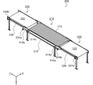
図5は、第1搬送装置310、第2搬送装置320、および、第3搬送装置330の斜視図であり、図6は、第1搬送装置310における第1搬送体312を説明するための斜視図である。
FIG. 5 is a perspective view of the
図5に示すように、第1搬送装置310は、被照射物Wを搬送する第1搬送体312と、第1搬送体312を駆動する第1ギア314a、314bと、第1ギア314aと第1ギア314bとに歯合するチェーンベルト316とを含んで構成される。
As shown in FIG. 5, the
詳細に説明すると、図6に示すように、第1搬送装置310の第1搬送体312は、搬送方向(図6中、Z軸方向)の幅が鉛直方向(図6中、Y軸方向)よりも短く形成された、ステンレス製の板状のスラット部312aと、スラット部312aを支持する支持部312bとを含んで構成される。スラット部312aの搬送方向の幅は、例えば、3mmであり、鉛直方向の幅は、例えば15mmであり、図6中、X軸方向の長さは、例えば700mmである。また、スラット部312a間の距離(図6中、Z軸方向の距離)は、例えば、25mmである。
More specifically, as shown in FIG. 6, the
このように、照射領域Rを通過する第1搬送体312のスラット部312aにおいて、電子線が照射される面(図6中、XZ平面)の面積を小さく形成することにより、電子線の照射によるスラット部312aの温度上昇を低減することができる。したがって、スラット部312aが変形してしまったり、腐食してしまったりする事態を回避することができる。
Thus, in the
なお、支持部312bの両端には、第1ギア314a、314bと歯合するチェーンベルト(不図示)が接続されており、第1ギア314a、314bが回転することにより、チェーンベルトが移動するとともに、スラット部312aおよび支持部312bが搬送方向に移動する。
Note that a chain belt (not shown) that meshes with the
図5に戻って説明すると、第2搬送装置320は、コンベア等で構成され、被照射物Wを搬送する第2搬送体322と、第2搬送体322を駆動する第2ギア324a、324bと、第2ギア324aと第2ギア324bとに歯合するチェーンベルト326とを含んで構成される。ここで、第2ギア324aと第2ギア324bとの歯数は実質的に等しく、第1ギア314aと、第2ギア324bとの減速比は、1.2:1(第1ギア314aの歯数/第2ギア324bの歯数=1.2)である。
Returning to FIG. 5, the
なお、第2搬送体322の両端には、第2ギア324a、324bと歯合するチェーンベルト(不図示)が接続されており、第2ギア324a、324bが回転することにより、チェーンベルトが移動するとともに、第2搬送体322が搬送方向に移動する。
Note that chain belts (not shown) that mesh with the
第3搬送装置330は、コンベア等で構成され、被照射物Wを搬送する第3搬送体332と、第3搬送体332を駆動する第3ギア334a、334bと、第3ギア334aと第3ギア334bとに歯合するチェーンベルト336とを含んで構成される。ここで、第3ギア334aと第3ギア334bとの歯数は実質的に等しく、第3ギア334aの歯数は、第2ギア324bの歯数と実質的に等しい。すなわち、第1ギア314bと、第3ギア334aとの減速比は、1.2:1(第1ギア314bの歯数/第3ギア334aの歯数=1.2)である。
The
なお、第3搬送体332の両端には、第3ギア334a、334bと歯合するチェーンベルト(不図示)が接続されており、第3ギア334a、334bが回転することにより、チェーンベルトが移動するとともに、第3搬送体332が搬送方向に移動する。
Note that chain belts (not shown) that mesh with the
また、搬送システム300は、第1ギア314aと第2ギア324bとを歯合するチェーンベルト410aと、第1ギア314bと第3ギア334aとを歯合するチェーンベルト410bと、第1ギア314aを回転させる不図示のモータを備える。
Further, the
したがって、モータによって第1ギア314aが回転すると、チェーンベルト316を通じて第1ギア314bが回転し、これによって支持部312bに接続された不図示のチェーンベルトが移動して第1搬送体312が駆動される。また、モータの回転によって第1ギア314aが回転すると、チェーンベルト410aを通じて第2ギア324bが回転し、この第2ギア324bの回転がチェーンベルト326を通じて第2ギア324aに伝達される。これにより、第2搬送体322の両端に接続された不図示のチェーンベルトが回転して第2搬送体322が駆動される。さらに、モータの回転によって第1ギア314bが回転すると、チェーンベルト410bを通じて第3ギア334aが回転し、この第3ギア334aの回転がチェーンベルト336を通じて第3ギア334bに伝達される。これにより、第3搬送体332の両端に接続された不図示のチェーンベルトが回転して第3搬送体332が駆動される。
Therefore, when the
換言すれば、モータが第1ギア314aを回転させるだけで、第1搬送体312、第2搬送体322、第3搬送体332の3つの搬送体を駆動させることができる。
In other words, the three transport bodies of the
また、上述したように、第1ギア314aの歯数と、第2ギア324bの歯数とを異ならせるとともに、第1ギア314bの歯数と、第3ギア334aの歯数とを異ならせることによって、モータが第1ギア314aを回転させるだけで、第1搬送体312の搬送速度V1と、第2搬送体322の搬送速度V2および第3搬送体332の搬送速度V3とを異ならせることができる。
Further, as described above, the number of teeth of the
また、第1ギア314a、314b、第2ギア324a、324b、第3ギア334a、334bの歯数は、常に一定であるため、搬送速度V2およびV3は、搬送速度V1に対して所定の比率が維持される関係にあることになる。ここでは、第1ギア314aと第1ギア314bの歯数、第2ギア324aと第2ギア324bの歯数、第3ギア334aと第3ギア334bの歯数、がそれぞれ等しく、第1ギア314aの歯数は、第2ギア324bの歯数の1.2倍であり、第1ギア314bの歯数は、第3ギア334aの歯数の1.2倍であるため、搬送速度V2および搬送速度V3は、搬送速度V1の1.2倍になる。したがって、制御装置390は、モータの回転数を制御して搬送速度V1を制御するだけで、搬送速度V2および搬送速度V3を制御することも可能となる。
Further, since the number of teeth of the
このように、第1搬送装置310、第2搬送装置320、第3搬送装置330それぞれがギアを備え、各搬送体を駆動するギア同士をチェーンベルト410a、410bで歯合させることにより、1つのモータでいずれかのギアを回転させれば、第1搬送体312、第2搬送体322、第3搬送体332のすべての搬送体を駆動することができる。したがって、第1搬送装置310、第2搬送装置320、第3搬送装置330の駆動源を一つに纏めることができ、搬送システム300全体のコストを低減することが可能となる。
As described above, each of the
また、制御装置390は、搬送速度V4、搬送速度V5、搬送速度V6を搬送速度V2と実質的に等しくなるように制御する。
Further, the
以上説明したように、被照射物Wを照射領域Rに通過させる搬送装置である第1搬送装置310の搬送速度V1を、搬送速度V2より遅くすることで、照射領域Rにおいて、被照射物W同士を密接して搬送することができる。これにより、被照射物Wに照射されない電子線を低減することができる。
As described above, the irradiation object W is irradiated in the irradiation region R by making the conveyance speed V1 of the
また、制御装置390は、被照射物判定部380が検出した被照射物Wによって決定される搬送速度V1に基づいて、送出部370の送出間隔PTを算出し、算出した送出間隔PTに基づいて送出部370に被照射物Wを送出させる。そして、第1搬送装置310、第2搬送装置320、第3搬送装置330それぞれがギアを備え、各搬送体を駆動するギア同士をチェーンベルト410a、410bで歯合させる構成であるため、制御装置390が第1ギア314aを回転させるモータの回転数を制御するだけで、搬送速度V1、搬送速度V2、搬送速度V3を制御することができる。したがって、ユーザが、被照射物Wごとに搬送速度V1、搬送速度V2、送出間隔PTを設定せずとも、照射領域Rにおいて適切に被照射物Wを密接させて搬送することが可能となる。
Further, the
さらに、搬送速度V3を搬送速度V1よりも速くすることで、第1搬送装置310で密接して搬送された被照射物Wを離隔することができる。これにより、第3搬送装置330において、カウンタ382が被照射物Wを確実にカウントすることができ、照射領域Rにおいて電子線が照射され、滅菌された被照射物Wの個数管理を確実に遂行することが可能となる。
Furthermore, the irradiation object W conveyed closely by the
ところで、上述したように、本実施形態において電子線は、電子線照射装置200から鉛直下方向に向かって照射されるが、このときスキャンホーン120によって水平方向に走査される(図2参照)。したがって、電子線は、図2中、Y軸方向に向かって、X軸方向に裾広がりに照射されることになる。ここで、被照射物Wの搬送方向と直交する方向(図2中、X軸方向)の長さを、照射領域Rにおける図2中X軸方向の長さと一致させれば、被照射物Wに照射されない電子線がなくなり、無駄な電子線の照射をさらに低減することができる。
By the way, as described above, in the present embodiment, the electron beam is irradiated from the electron
そこで、本実施形態の第1搬送装置310は、昇降機構を備える。図7は、第1搬送装置310の昇降機構420を説明するための説明図である。図7に示すように、第1搬送装置310には、第1搬送体312を昇降する昇降機構420が設けられている。昇降機構420は、図7(a)に示す通常状態において、第1搬送体312が第2搬送体322、第3搬送体332と鉛直方向(図7中、Y軸方向)の高さが実質的に等しくなるように、第1搬送体312の高さを維持する。
Therefore, the
ここで、例えば、被照射物判定部380が検出した被照射物Wの搬送方向と直交する方向(図7中、X軸方向)の長さが、図7中、X軸方向における照射領域Rの幅より短い場合、図7(b)に示すように、制御装置390は、昇降機構420を駆動して、第1搬送体312を鉛直上方向に移動させる。そうすると、被照射物Wと電子線取出部124との距離が近くなり、被照射物Wの搬送方向と直交する方向の長さが、図7中、X軸方向における照射領域Rの幅に近づく(または一致する)ことになる。なお、ここで、チェーンベルト410a、410bは、昇降機構420による第1搬送体312の昇降を許容する程度の遊びを有するように、第1ギア314a、314bと歯合している。
Here, for example, the length in the direction (X-axis direction in FIG. 7) perpendicular to the conveyance direction of the irradiation object W detected by the irradiation-
このように、第1搬送装置310が昇降機構420を備え、制御装置390が被照射物Wの搬送方向と直交する方向の長さに応じて、昇降機構420を制御して第1搬送体312を昇降させる。これにより、被照射物Wの搬送方向と直交する方向の長さと、図7中、X軸方向における照射領域Rの幅を一致させることができ、被照射物W以外に照射される電子線をさらに低減することが可能となる。
Thus, the
以上、添付図面を参照しながら本発明の好適な実施形態について説明したが、本発明はかかる実施形態に限定されないことは言うまでもない。当業者であれば、特許請求の範囲に記載された範疇において、各種の変更例または修正例に想到し得ることは明らかであり、それらについても当然に本発明の技術的範囲に属するものと了解される。 As mentioned above, although preferred embodiment of this invention was described referring an accompanying drawing, it cannot be overemphasized that this invention is not limited to this embodiment. It will be apparent to those skilled in the art that various changes and modifications can be made within the scope of the claims, and these are naturally within the technical scope of the present invention. Is done.
例えば、上述した実施形態では、被照射物Wの長さL0を検出する被照射物判定部380を設けているが、ユーザが制御装置390に被照射物Wの長さL0を入力してもよい。また、上述した実施形態では、被照射物判定部380は、照射領域Rにおける被照射物Wの搬送方向の長さL0を検出しているが、制御装置390が、被照射物Wの種類ごとに、電子線の照射時間を予め記憶しておき、被照射物判定部380が被照射物Wの種類を検出することもできる。この場合、制御装置390は、送出間隔PTを照射時間とする。
For example, in the above-described embodiment, the irradiation
また、上述した実施形態では、制御装置390が、搬送速度V1と搬送速度V2とを所定の比率に維持しているため、制御装置390は、搬送速度V1および送出間隔PTを算出して、モータおよび送出部370を制御すれば、第1搬送装置310において被照射物Wを密接させて搬送することができる。
In the above-described embodiment, since the
しかし、制御装置390が、搬送速度V1と搬送速度V2とを所定の比率に維持しない場合、制御装置390は、搬送速度V1、搬送速度V2、および送出間隔PTを、被照射物Wに応じて別々に設定することで、第1搬送装置310において被照射物Wを密接させて搬送することができる。
However, when the
例えば、制御装置390は、まず、電子線照射装置200によって放出される電子線の出力と、被照射物判定部380が検出した被照射物Wの長さL0に基づいて、搬送速度V1を決定する。続いて、制御装置390は、予め記憶している第2搬送装置320の搬送距離L2と、被照射物判定部380が判定した被照射物Wの長さL0に応じて、第1搬送装置310において被照射物Wが密接して搬送されるように、送出間隔PTを算出する。すなわち、制御装置390は、送出部370に送出された被照射物W2が、L0/V1sec後に、第2搬送装置320から第1搬送装置310に載置され始めるように搬送速度V2を算出する。
For example, the
つまり、制御装置390は、第2搬送装置320の長さL2の距離をL0/V1secで搬送できる速度を、搬送速度V2(V2=L2/(L0/V1)=L2×V1/L0)とする。なお、このとき、算出した搬送速度V2が第2搬送装置320の搬送能力を超えている場合、搬送速度V2を第2搬送装置320における最大値に設定し、送出間隔PTを制御するとよい。そうすると、図4(b)に示す状態のときに、第2搬送装置320には、被照射物W1、被照射物W2、被照射物W3が載置されることになる。
That is, the
また、上述した実施形態では、第1搬送装置310が昇降機構420を備えることにより、被照射物Wの鉛直方向の高さを変更しているが、制御装置390がスキャン電磁石122を制御して、スキャン電磁石122による電子線のスキャン幅を変更することによって、被照射物Wの搬送方向と直交する方向の長さと、図7中、X軸方向における照射方向Rの幅を一致させることもできる。
In the above-described embodiment, the vertical height of the irradiation object W is changed by the
本発明は、被照射物に電子線を照射する電子線照射システムおよび搬送システムに利用することができる。 INDUSTRIAL APPLICABILITY The present invention can be used for an electron beam irradiation system and a transport system that irradiate an object with an electron beam.
R …照射領域
V1 …搬送速度
V2 …搬送速度
W …被照射物
100 …電子線照射システム
200 …電子線照射装置
300 …搬送システム
310 …第1搬送装置
312 …第1搬送体
314 …第1ギア
320 …第2搬送装置
322 …第2搬送体
324 …第2ギア
70 …送出部
390 …制御装置
410 …チェーンベルト
R ... Irradiation area V1 ... Conveying speed V2 ... Conveying speed W ...
Claims (4)
前記被照射物を搬送するとともに、前記電子線照射装置によって前記被照射物に電子線が照射される領域である照射領域に該被照射物を通過させる第1搬送装置と、
前記第1搬送装置よりも前記被照射物の搬送方向上流側に設けられ、前記第1搬送装置の搬送速度よりも速い搬送速度で前記被照射物を搬送するとともに、前記第1搬送装置に該被照射物を搬出する第2搬送装置と、
前記第2搬送装置に前記被照射物を送出する送出部と、
前記被照射物に応じて、前記第1搬送装置の搬送速度、前記第2搬送装置の搬送速度、および、前記送出部の送出間隔を制御する制御装置と、
を備えたことを特徴とする電子線照射システム。 An electron beam irradiation apparatus for irradiating an object with an electron beam;
A first transport device that transports the irradiated object and passes the irradiated object to an irradiation area that is an area where the electron beam irradiation apparatus irradiates the electron beam with the electron beam irradiation apparatus;
Provided on the upstream side of the first transport device in the transport direction of the irradiated object, transports the irradiated object at a transport speed faster than the transport speed of the first transport device, and A second transfer device for carrying out the irradiated object;
A delivery section for delivering the irradiated object to the second transport device;
A control device for controlling the transport speed of the first transport device, the transport speed of the second transport device, and the sending interval of the sending section according to the object to be irradiated;
An electron beam irradiation system comprising:
前記第1搬送装置の搬送速度と、前記第2搬送装置の搬送速度とを所定の比率に維持することを特徴とする請求項1に記載の電子線照射システム。 The controller is
The electron beam irradiation system according to claim 1, wherein the transport speed of the first transport device and the transport speed of the second transport device are maintained at a predetermined ratio.
前記被照射物を搬送する第1搬送体を含んで構成され、
前記第2搬送装置は、
前記被照射物を搬送する第2搬送体を含んで構成され、
前記第1搬送体および前記第2搬送体は、前記制御装置によって回転数が制御される1つのモータに連結され、
前記制御装置は前記1つのモータを回転させることにより、前記第1搬送装置の搬送速度と、前記第2搬送装置の搬送速度とを異ならせることを特徴とする請求項1または2記載の電子線照射システム。 The first transport device is
A first transport body configured to transport the irradiation object;
The second transport device is
A second transport body for transporting the irradiated object;
The first transport body and the second transport body are connected to one motor whose rotational speed is controlled by the control device,
3. The electron beam according to claim 1, wherein the control device makes the transport speed of the first transport device different from the transport speed of the second transport device by rotating the one motor. 4. Irradiation system.
前記被照射物を搬送するとともに、前記電子線照射装置によって前記被照射物に電子線が照射される領域である照射領域に該被照射物を通過させる第1搬送装置と、
前記第1搬送装置よりも前記被照射物の搬送方向上流側に設けられ、前記第1搬送装置の搬送速度よりも速い搬送速度で前記被照射物を搬送するとともに、前記第1搬送装置に該被照射物を搬出する第2搬送装置と、
前記第2搬送装置に前記被照射物を送出する送出部と、
前記被照射物に応じて、前記第1搬送装置の搬送速度、前記第2搬送装置の搬送速度、および、前記送出部の送出間隔を制御する制御装置と、
を備えたことを特徴とする搬送システム。 A transport system for transporting the irradiated object to an electron beam irradiation apparatus that irradiates the irradiated object with an electron beam,
A first transport device that transports the irradiated object and passes the irradiated object to an irradiation area that is an area where the electron beam irradiation apparatus irradiates the electron beam with the electron beam irradiation apparatus;
Provided on the upstream side of the first transport device in the transport direction of the irradiated object, transports the irradiated object at a transport speed faster than the transport speed of the first transport device, and A second transfer device for carrying out the irradiated object;
A delivery section for delivering the irradiated object to the second transport device;
A control device for controlling the transport speed of the first transport device, the transport speed of the second transport device, and the sending interval of the sending section according to the object to be irradiated;
A conveyance system characterized by comprising:
Priority Applications (1)
| Application Number | Priority Date | Filing Date | Title |
|---|---|---|---|
| JP2011116816A JP2012247207A (en) | 2011-05-25 | 2011-05-25 | Electron beam irradiation system and conveyance system |
Applications Claiming Priority (1)
| Application Number | Priority Date | Filing Date | Title |
|---|---|---|---|
| JP2011116816A JP2012247207A (en) | 2011-05-25 | 2011-05-25 | Electron beam irradiation system and conveyance system |
Publications (1)
| Publication Number | Publication Date |
|---|---|
| JP2012247207A true JP2012247207A (en) | 2012-12-13 |
Family
ID=47467800
Family Applications (1)
| Application Number | Title | Priority Date | Filing Date |
|---|---|---|---|
| JP2011116816A Pending JP2012247207A (en) | 2011-05-25 | 2011-05-25 | Electron beam irradiation system and conveyance system |
Country Status (1)
| Country | Link |
|---|---|
| JP (1) | JP2012247207A (en) |
Cited By (3)
| Publication number | Priority date | Publication date | Assignee | Title |
|---|---|---|---|---|
| WO2014073446A1 (en) | 2012-11-09 | 2014-05-15 | ソニー株式会社 | Photoelectric conversion element, solid-state imaging device and electronic device |
| CN104749020A (en) * | 2013-12-30 | 2015-07-01 | 同方威视技术股份有限公司 | Port fruits quarantine and irradiation treatment method by accelerator and device thereof |
| CN111899910A (en) * | 2020-07-15 | 2020-11-06 | 四川润祥辐照技术有限公司 | Electron beam irradiation method and irradiation system |
Citations (6)
| Publication number | Priority date | Publication date | Assignee | Title |
|---|---|---|---|---|
| JPS6226063A (en) * | 1985-07-29 | 1987-02-04 | 豊田メデイカル株式会社 | Futon sterilizing apparatus |
| JPH08508100A (en) * | 1993-03-19 | 1996-08-27 | ザ タイタン コーポレイション | Irradiation system utilizing conveyor moving article carrier |
| JP2001242296A (en) * | 2000-02-25 | 2001-09-07 | Nuclear Fuel Ind Ltd | Electron beam irradiation equipment |
| JP2002006098A (en) * | 2000-06-26 | 2002-01-09 | Mitsubishi Heavy Ind Ltd | Method and device for electron beam irradiation |
| JP2002006099A (en) * | 2000-06-26 | 2002-01-09 | Mitsubishi Heavy Ind Ltd | Method and device for electron beam irradiation |
| JP2003503112A (en) * | 1999-06-30 | 2003-01-28 | ザ タイタン コーポレイション | System and method for irradiating an article to sterilize the article |
-
2011
- 2011-05-25 JP JP2011116816A patent/JP2012247207A/en active Pending
Patent Citations (6)
| Publication number | Priority date | Publication date | Assignee | Title |
|---|---|---|---|---|
| JPS6226063A (en) * | 1985-07-29 | 1987-02-04 | 豊田メデイカル株式会社 | Futon sterilizing apparatus |
| JPH08508100A (en) * | 1993-03-19 | 1996-08-27 | ザ タイタン コーポレイション | Irradiation system utilizing conveyor moving article carrier |
| JP2003503112A (en) * | 1999-06-30 | 2003-01-28 | ザ タイタン コーポレイション | System and method for irradiating an article to sterilize the article |
| JP2001242296A (en) * | 2000-02-25 | 2001-09-07 | Nuclear Fuel Ind Ltd | Electron beam irradiation equipment |
| JP2002006098A (en) * | 2000-06-26 | 2002-01-09 | Mitsubishi Heavy Ind Ltd | Method and device for electron beam irradiation |
| JP2002006099A (en) * | 2000-06-26 | 2002-01-09 | Mitsubishi Heavy Ind Ltd | Method and device for electron beam irradiation |
Cited By (5)
| Publication number | Priority date | Publication date | Assignee | Title |
|---|---|---|---|---|
| WO2014073446A1 (en) | 2012-11-09 | 2014-05-15 | ソニー株式会社 | Photoelectric conversion element, solid-state imaging device and electronic device |
| EP3767697A1 (en) | 2012-11-09 | 2021-01-20 | Sony Corporation | Photoelectric conversion device, solid-state image pickup unit, and electronic apparatus |
| CN104749020A (en) * | 2013-12-30 | 2015-07-01 | 同方威视技术股份有限公司 | Port fruits quarantine and irradiation treatment method by accelerator and device thereof |
| CN111899910A (en) * | 2020-07-15 | 2020-11-06 | 四川润祥辐照技术有限公司 | Electron beam irradiation method and irradiation system |
| CN111899910B (en) * | 2020-07-15 | 2023-04-25 | 四川润祥辐照技术有限公司 | Electron beam irradiation method and irradiation system |
Similar Documents
| Publication | Publication Date | Title |
|---|---|---|
| KR101411055B1 (en) | Particle beam irradiation system and charged particle beam correcting method | |
| US6653641B2 (en) | Bulk material irradiation system and method | |
| JP5638606B2 (en) | Energy degrader and charged particle irradiation system including the same | |
| JP5597162B2 (en) | Circular accelerator and operation method of circular accelerator | |
| CN101416267B (en) | Device and method for changing properties of three-dimensional shaped parts by means of electronics and use of said method | |
| CN107004453B (en) | Particle harness adjusts device and method, particle beam therapeutic apparatus | |
| CN102769990B (en) | Linear accelerator | |
| JP2015181552A (en) | Charged particle beam therapy apparatus and range adjustment method of charged particle beam | |
| CN101631420A (en) | Accelerator used for cancer therapy with protons-heavy ion beams | |
| CN105579099A (en) | Charged particle beam irradiation device | |
| CN114545481B (en) | Device for X-ray irradiation | |
| CN117203736A (en) | Devices, systems and methods for energy dispersive ion beams | |
| WO2022155315A1 (en) | Flash radiotherapy accelerator system | |
| JP2012242145A (en) | Electron beam irradiation apparatus | |
| US20210031056A1 (en) | Charged particle beam treatment apparatus | |
| Scholz et al. | First simultaneous operation of two SASE beamlines in FLASH | |
| JP6211736B2 (en) | Charged particle beam therapy system | |
| JP2018503565A (en) | Electron beam sterilization system having an external sterilization emitter that moves relative to the object to be sterilized | |
| Obier et al. | Long pulse kicker for European XFEL beam distribution | |
| Deshpande et al. | Experimental results of an rf gun and the generation of a multibunch beam | |
| JP2013053924A (en) | Electron beam irradiation apparatus and scan horn for the same | |
| JP5350307B2 (en) | Particle beam therapy system | |
| JP2013002936A (en) | Conveyance structure for object to be irradiated | |
| JP2014107278A (en) | Method for manufacturing semiconductor device, substrate processing system, and substrate processing device | |
| JP2013002935A (en) | Electron beam irradiation system |
Legal Events
| Date | Code | Title | Description |
|---|---|---|---|
| A621 | Written request for application examination |
Free format text: JAPANESE INTERMEDIATE CODE: A621 Effective date: 20140219 |
|
| A977 | Report on retrieval |
Free format text: JAPANESE INTERMEDIATE CODE: A971007 Effective date: 20141113 |
|
| A131 | Notification of reasons for refusal |
Free format text: JAPANESE INTERMEDIATE CODE: A131 Effective date: 20141125 |
|
| A02 | Decision of refusal |
Free format text: JAPANESE INTERMEDIATE CODE: A02 Effective date: 20150324 |