JP2012247228A - Float - Google Patents
Float Download PDFInfo
- Publication number
- JP2012247228A JP2012247228A JP2011117363A JP2011117363A JP2012247228A JP 2012247228 A JP2012247228 A JP 2012247228A JP 2011117363 A JP2011117363 A JP 2011117363A JP 2011117363 A JP2011117363 A JP 2011117363A JP 2012247228 A JP2012247228 A JP 2012247228A
- Authority
- JP
- Japan
- Prior art keywords
- lid
- cup
- side rib
- lid body
- float
- Prior art date
- Legal status (The legal status is an assumption and is not a legal conclusion. Google has not performed a legal analysis and makes no representation as to the accuracy of the status listed.)
- Withdrawn
Links
- 239000002828 fuel tank Substances 0.000 claims abstract description 21
- 239000000446 fuel Substances 0.000 claims description 18
- 239000007788 liquid Substances 0.000 claims description 11
- 230000005489 elastic deformation Effects 0.000 claims description 5
- 238000003466 welding Methods 0.000 abstract description 31
- 230000002093 peripheral effect Effects 0.000 description 30
- LCGLNKUTAGEVQW-UHFFFAOYSA-N Dimethyl ether Chemical compound COC LCGLNKUTAGEVQW-UHFFFAOYSA-N 0.000 description 12
- 239000007789 gas Substances 0.000 description 10
- 239000011347 resin Substances 0.000 description 7
- 229920005989 resin Polymers 0.000 description 7
- 239000004734 Polyphenylene sulfide Substances 0.000 description 6
- 229920000069 polyphenylene sulfide Polymers 0.000 description 6
- 230000002265 prevention Effects 0.000 description 6
- 230000000694 effects Effects 0.000 description 5
- 239000003915 liquefied petroleum gas Substances 0.000 description 4
- 239000012783 reinforcing fiber Substances 0.000 description 3
- 229920000049 Carbon (fiber) Polymers 0.000 description 2
- 239000004917 carbon fiber Substances 0.000 description 2
- 238000000465 moulding Methods 0.000 description 2
- 239000000835 fiber Substances 0.000 description 1
- 239000003365 glass fiber Substances 0.000 description 1
- 239000000463 material Substances 0.000 description 1
- VNWKTOKETHGBQD-UHFFFAOYSA-N methane Chemical compound C VNWKTOKETHGBQD-UHFFFAOYSA-N 0.000 description 1
- 238000000034 method Methods 0.000 description 1
- 230000000149 penetrating effect Effects 0.000 description 1
Images

Landscapes
- Closures For Containers (AREA)
- Level Indicators Using A Float (AREA)
- Cooling, Air Intake And Gas Exhaust, And Fuel Tank Arrangements In Propulsion Units (AREA)
Abstract
Description
本発明は、ガスや液体等の燃料を貯留する燃料タンクに配設され、該燃料の液面高さに従って浮動するフロートに関する。 The present invention relates to a float that is disposed in a fuel tank that stores fuel such as gas or liquid, and floats according to the liquid level of the fuel.
例えば、液化石油ガス(以下、LPGという)やジメチルエーテル(以下、DMEという)等の液化ガス燃料を貯留する燃料タンクには、液面計や過充填防止装置等が配設されている。液面計や過充填防止装置は、一般的に、タンク内に貯留する燃料の液面高さに伴って浮動するフロートを備えている。 For example, a fuel tank that stores liquefied gas fuel such as liquefied petroleum gas (hereinafter referred to as LPG) or dimethyl ether (hereinafter referred to as DME) is provided with a liquid level gauge, an overfill prevention device, and the like. Liquid level gauges and overfill prevention devices generally include a float that floats with the liquid level of the fuel stored in the tank.
このようなフロートとして、例えば特許文献1の構成が提案されている。この従来構成のフロートは、一端を開口し且つ他端を閉鎖した円筒状のカップ体に、前記開口を閉鎖する蓋体を溶着してなる中空体であり、カップ体の内部にはリブが形成されている。このフロートでは、リブの形成によりカップ体の強度を向上させている。 As such a float, for example, the configuration of Patent Document 1 is proposed. The float of this conventional configuration is a hollow body formed by welding a lid body that closes the opening to a cylindrical cup body that is open at one end and closed at the other end, and a rib is formed inside the cup body. Has been. In this float, the strength of the cup body is improved by forming ribs.
上述したフロートにおいて、さらなる強度向上が求められる場合には、カップ体だけでなく蓋体の強度向上も必要である。また、カップ体と蓋体とを溶着した溶着部の強度向上も必要である。 In the above-described float, when further improvement in strength is required, it is necessary to improve not only the cup body but also the lid body. Moreover, the strength improvement of the welding part which welded the cup body and the cover body is also required.
本発明は、より高い強度を発揮し得るフロートを提供するものである。 The present invention provides a float that can exhibit higher strength.
本発明は、少なくとも一端に開口部を有する円筒状のカップ体と、該カップ体に溶着されて開口部を閉鎖する円板状の蓋体とから構成され、燃料タンク内に貯留する燃料の液面高さに伴って浮動する中空状のフロートにおいて、前記カップ体は、その内部にカップ側リブを備え、前記蓋体は、蓋内面からカップ体側へ突成された蓋側リブを備え、前記蓋体に外力が作用しない状態で、カップ側リブと蓋側リブとが離間し、外力が作用した状態で、蓋体の弾性変形によってカップ側リブと蓋側リブとが接触するように、カップ側リブと蓋側リブとが形成されていることを特徴とするフロートである。 The present invention comprises a cylindrical cup body having an opening at at least one end, and a disc-shaped lid body welded to the cup body to close the opening, and a liquid of fuel stored in a fuel tank In the hollow float that floats with the surface height, the cup body includes a cup side rib therein, and the lid body includes a lid side rib protruding from the inner surface of the lid toward the cup body side, The cup side rib and the lid side rib are separated from each other with no external force acting on the lid, and the cup side rib and the lid side rib are brought into contact with each other by the elastic deformation of the lid while the external force is applied. The float is characterized in that a side rib and a lid side rib are formed.
かかる構成では、蓋側リブを設けることにより蓋体自体の強度を向上できる。また、蓋体に外力が作用すると該蓋体が弾性変形してたわみ、蓋体とカップ体との溶着部に作用する応力が高くなる。本構成では、蓋体が弾性変形すると蓋側リブとカップ側リブとが接触することから、蓋体に外力が作用したときに生ずる蓋体のたわみ量を抑制し、蓋体に作用する応力や前記溶着部に作用する応力が高くなりすぎることを抑制できる。これにより、蓋体や溶着部の強度を向上させることができる。 In such a configuration, the strength of the lid itself can be improved by providing the lid-side rib. Further, when an external force is applied to the lid, the lid is elastically deformed and bent, and the stress acting on the welded portion between the lid and the cup increases. In this configuration, when the lid is elastically deformed, the lid-side rib and the cup-side rib come into contact with each other. Therefore, the amount of deflection of the lid that occurs when an external force is applied to the lid is suppressed, and the stress acting on the lid It can suppress that the stress which acts on the said welding part becomes high too much. Thereby, the intensity | strength of a cover body or a welding part can be improved.
また、外力が作用しない状態でカップ側リブと蓋側リブとが接触しないことから、カップ体と蓋体とを溶着する際に、カップ体に対する蓋体の位置決めを精度良く行うことができる。この精度良い位置決めにより、カップ体と蓋体とを正確かつ十分に接触している状態で溶着できるため、適切な溶着を安定して行うことができる。尚仮に、カップ側リブと蓋側リブとがそれぞれの高さ寸法のバラツキによって接触してしまう場合には、前記位置決めを精度良く行うことが難しい。この場合、カップ体と蓋体とを正確かつ十分に接触していない状態で溶着するため、溶着が不十分となって溶着部の強度が低下してしまう。これに対し、本構成では、前記のように精度の良い位置決めができることにより正確かつ十分に溶着でき、カップ体と蓋体との溶着品質を高めることができる。これにより、溶着部の強度を向上させることができる。 In addition, since the cup-side rib and the lid-side rib are not in contact with each other when no external force is applied, the lid can be accurately positioned with respect to the cup when the cup and the lid are welded. Since the cup body and the lid body can be welded accurately and sufficiently by this accurate positioning, appropriate welding can be performed stably. If the cup-side rib and the lid-side rib come into contact with each other due to variations in height, it is difficult to perform the positioning with high accuracy. In this case, since the cup body and the lid body are welded in a state where they are not accurately and sufficiently in contact with each other, the welding is insufficient and the strength of the welded portion is reduced. On the other hand, in this structure, since it can position accurately, as mentioned above, it can weld correctly and fully, and can improve the welding quality of a cup body and a cover body. Thereby, the intensity | strength of a welding part can be improved.
上述した本発明のフロートにおいて、蓋側リブは、蓋内面からカップ体側へ環状に突成されている構成が提案される。 In the above-described float of the present invention, a configuration is proposed in which the lid-side rib projects in an annular shape from the inner surface of the lid toward the cup body.
かかる構成では、蓋側リブが環状に形成されていることから、蓋体とカップ体との周方向位置関係に関わらず、蓋体の弾性変形によって蓋側リブとカップ側リブとが接触する。そのため、蓋体とカップ体とを周方向の任意位置で溶着しても、蓋体のたわみ量を抑制して蓋体に作用する応力や上記溶着部に作用する応力を低減して蓋体や溶着部の強度を向上させる効果を発揮できる。 In such a configuration, since the lid-side rib is formed in an annular shape, the lid-side rib and the cup-side rib come into contact with each other by elastic deformation of the lid, regardless of the circumferential positional relationship between the lid and the cup. Therefore, even if the lid body and the cup body are welded at an arbitrary position in the circumferential direction, the lid body and the stress acting on the weld body and the stress acting on the welded portion can be reduced by suppressing the deflection amount of the lid body. The effect of improving the strength of the welded portion can be exhibited.
上述した本発明のフロートにおいて、カップ側リブは、該カップ体の径方向中央部から径方向外方へ放射状に形成されている構成が提案される。 In the float of the present invention described above, a configuration is proposed in which the cup-side ribs are formed radially outward from the radial center of the cup body.
かかる構成では、放射状のカップ側リブにより、燃料タンクの内圧によって蓋体が弾性変形した場合に、環状の蓋側リブと放射状のカップ側リブとが周方向で分散して接触することから、蓋体に作用する応力や蓋体とカップ体との溶着部に作用する応力が局所的に大きくなることを抑制できる。これにより、蓋体や溶着部の強度を向上させることができる。 In such a configuration, when the lid is elastically deformed by the internal pressure of the fuel tank due to the radial cup-side rib, the annular lid-side rib and the radial cup-side rib are dispersed and contacted in the circumferential direction. It can suppress that the stress which acts on a body, and the stress which acts on the welding part of a cover body and a cup body become large locally. Thereby, the intensity | strength of a cover body or a welding part can be improved.
上述した本発明のフロートにおいて、蓋側リブは、該蓋側リブよりも径方向外側にある蓋内面の面積と径方向内側にある蓋内面の面積とが略一致するように形成されている構成が提案される。 In the float of the present invention described above, the lid-side rib is formed such that the area of the lid inner surface that is radially outward of the lid-side rib and the area of the lid inner surface that is radially inner are substantially the same. Is proposed.
かかる構成では、蓋側リブにより区画される径方向内側の面積と径方向外側の面積とが略一致することから、燃料タンクの内圧によって該径方向内側の面と径方向外側の面とに作用する荷重が略等しくなる。これにより、蓋体や溶着部に作用する応力をより適切に分散させることができ、蓋体や溶着部の強度を向上させることができる。 In such a configuration, the area on the radially inner side and the area on the radially outer side defined by the lid rib substantially coincide with each other, so that the inner pressure of the fuel tank acts on the radially inner surface and the radially outer surface. Load to be approximately equal. Thereby, the stress which acts on a cover and a welding part can be disperse | distributed more appropriately, and the intensity | strength of a cover and a welding part can be improved.
上述した本発明のフロートにおいて、蓋体は、蓋内面からカップ体側に突成された放射状のリブをさらに備えている構成が提案される。 In the float of the present invention described above, a configuration is proposed in which the lid further includes radial ribs protruding from the inner surface of the lid toward the cup body.
かかる構成では、放射状のリブによって蓋体の強度をより向上させることができる。また、蓋体を樹脂により成形する場合に、成形の際にヒケの発生を抑制できる。 In such a configuration, the strength of the lid can be further improved by the radial ribs. In addition, when the lid is molded from resin, the occurrence of sink marks can be suppressed during molding.
本発明のフロートは、上述したように、カップ体に設けられたカップ側リブと、蓋体に設けられた蓋側リブとが、該蓋体に外力が作用しない状態で離間し、前記外力が作用した状態で蓋体の弾性変形によって接触するように形成されたものであるから、蓋体に外力が作用したときに生ずる蓋体のたわみ量を抑制でき、蓋体に作用する応力や蓋体とカップ体との溶着部に作用する応力を低減できる。これにより、蓋体や溶着部の強度を向上させることができる。また、カップ体と蓋体とを溶着する際にカップ側リブと蓋側リブとが接触しないことから、カップ体に対する蓋体の位置決めを精度良く行うことができ、カップ体と蓋体とを正確かつ十分に接触している状態で溶着できるため、カップ体と蓋体との溶着品質を高めることができる。これにより、溶着部の強度を向上させることができる。 In the float of the present invention, as described above, the cup-side rib provided on the cup body and the lid-side rib provided on the lid body are separated in a state where no external force acts on the lid body, and the external force is Since it is formed so as to come into contact by elastic deformation of the lid in an acted state, the amount of deflection of the lid that occurs when an external force is applied to the lid can be suppressed, and the stress acting on the lid and the lid The stress acting on the welded portion between the cup body and the cup body can be reduced. Thereby, the intensity | strength of a cover body or a welding part can be improved. Further, since the cup-side rib and the lid-side rib do not come into contact with each other when the cup body and the lid body are welded, the lid body can be accurately positioned with respect to the cup body, and the cup body and the lid body can be accurately positioned. And since it can weld in the state which is fully contacting, the welding quality of a cup body and a cover body can be improved. Thereby, the intensity | strength of a welding part can be improved.
本発明の実施例を添付図面を用いて詳述する。
本実施例は、液化ガス燃料により駆動するエンジンを動力としたトラックなどの車両に配設される燃料タンク1である。ここで、液化ガス燃料には例えばLPG(液化石油ガス)燃料やDME(ジメチルエーテル)燃料が用いられる。
Embodiments of the present invention will be described in detail with reference to the accompanying drawings.
The present embodiment is a fuel tank 1 disposed in a vehicle such as a truck powered by an engine driven by liquefied gas fuel. Here, for example, LPG (liquefied petroleum gas) fuel or DME (dimethyl ether) fuel is used as the liquefied gas fuel.
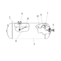
燃料タンク1は、図1のように、タンク本体2、該タンク本体2に配設されて液化ガス燃料の充填口として弁の開閉を行うバルブ装置5、タンク本体2に配設されて液化ガス燃料の液面位置を計測するための液面計6、タンク本体2の内部に設けられバルブ装置5と接続されて液化ガス燃料の所定量以上の充填を防止する過充填防止装置7などから構成されている。ここで、液面計6と過充填防止装置7とは、液化ガス燃料の液面に従って浮動するフロート21,21と各フロート21,21に連結されたアーム8,9とを夫々に備え、該フロート21が燃料タンク1内に貯留する液化ガス燃料の液面に従って浮動することにより機械的に作動する構成である。これら液面計6や過充填防止装置7は、従来から用いられているものを適用できるため、その詳細については省略する。このような燃料タンク1は、例えばトラックの車体側面下部に横置きに配設されるものであり、図示しない固定部材により車両に固定される。
As shown in FIG. 1, the fuel tank 1 includes a
次に、本発明の要部にかかる上記フロート21について説明する。
フロート21は、図2のように、カップ体22と蓋体23とが溶着されてなる中空体である。本実施例では、カップ体22と蓋体23とをポリフェニレンサルファイド樹脂(以下、PPS樹脂)により成形している。
Next, the said
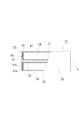
As shown in FIG. 2, the
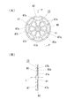
カップ体22は、図3のように、中心軸線Lに沿って円筒状に形成された内周部31と、該内周部31と同心かつ同じ長さ寸法で径寸法の大きい円筒状に形成された外周部25と、内周部31と外周部25の各端部のうちで同じ向きの一方の端部間を接続するように形成された底部26とを備え、さらに内周部31、外周部25および底部26とを接続する複数のカップ側リブ34を備えてなる。これら内周部31、外周部25、底部26およびカップ側リブ34とは、夫々に所定の肉厚で形成されている。カップ体22には、底部26と対向する側に開口される開口部30が設けられており、この開口部30側の内周部31と外周部25との各端部には上記蓋体23を嵌め合わせるための段差が設けられている。ここで、開口部30側の内周部31には、前記段差を構成する段部31aが該内周部31の外径よりも小さい径寸法で形成されており、開口部30側の外周部25には、前記段差を構成する段部25aが、該外周部25の内径よりも大きい径寸法で形成されている。これら段部31aおよび段部25aの中心軸線L方向の長さ寸法は、蓋体23の高さ寸法とほぼ同等に設定されている。また、前記カップ側リブ34は、中心軸線Lを中心とする放射状に形成されており、周方向に均等間隔で四箇所に設けられている。さらにまた、前記内周部31には中心軸線Lに沿って貫通する孔32が設けられており、上記した液面計6と過充填防止装置7とを構成する状態では上記したアーム8,9がこの孔32に嵌入して取り付けられる。
As shown in FIG. 3, the
一方、蓋体23は、図4のように、カップ体22と同様に、中心軸線Lに沿って円筒状に形成された内周部41と、該内周部41と同心かつ同じ長さ寸法で径寸法の大きい円筒状に形成された外周部42と、内周部41と外周部42の各端部のうちで同じ向きの一方の端部間を接続するように形成された底部40とを備え、さらに内周部41、外周部42および底部40とを接続する複数の蓋側リブ47を備えてなる。これら内周部41、外周部42、底部40および蓋側リブ47とは、夫々に所定の肉厚で形成されている。そして、蓋体23は、上記カップ体22に比して中心軸線L方向の長さ寸法が短く設定されている。また、蓋体23は、内周部41と外周部42とが夫々にカップ体22の段部31a,25aに嵌め合わされるように形成されている。
On the other hand, as shown in FIG. 4, the
上記の蓋側リブ47は、中心軸線Lを中心とする放射状に形成され周方向に均等間隔で八箇所に設けられたリブ47aと、中心軸線Lと中心として円環状に形成されたリブ47bとが一体的に構成されてなる。この蓋側リブ47は、その放射状に形成されたリブ47aによって蓋体23自体の強度を向上させる効果があると共に、蓋体23をPPS樹脂により成形する際のヒケの発生を抑制できる。
The lid-
フロート21は、図2のように、蓋体23の蓋側リブ47が形成された側をカップ体22の開口部30側に向けて、蓋体23の内周部41と外周部42とを夫々にカップ体22の段部31aと段部25aとに嵌め合わせ、これら嵌め合わせた部位を接合することによって形成される。ここで、カップ体22と蓋体23とは、両者を嵌め合わせた部位を全周に亘って超音波溶着することにより接合される。これにより、フロート21には、その内部に密閉された内部空域が形成される。尚、超音波溶着については、従来から使用されている溶着方法を適用できるため、その詳細については省略する。
As shown in FIG. 2, the
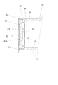
カップ体22のカップ側リブ34と蓋体23の蓋側リブ47とは、フロート21において蓋体23に外力が作用しない状態でカップ側リブ34と蓋側リブ47とが離間し、蓋体23に外力が作用した状態で蓋体23の弾性変形によってカップ側リブ34と蓋側リブ47とが接触するように、夫々に形成されている。フロート21は、燃料タンク1の内部で、燃料タンク1に貯留される液化ガス燃料に曝されると共に、燃料タンク1の内圧を受けて蓋体23はこの内圧による外力を受ける。ここで、図5に、蓋体23が外力によりたわんでいる状態を示す。図5のように、蓋体23に外力が作用すると、該蓋体23が弾性変形してたわみ、蓋体23とカップ体22との溶着部に作用する応力が高くなる。本実施例のフロート21では、蓋体23が弾性変形すると蓋側リブ47とカップ側リブ34とが接触するように形成されていることから、蓋体23に外力が作用したときの蓋体23のたわみ量を抑制し、蓋体23に作用する応力や溶着部に作用する応力が高くなりすぎることを抑制できる。これにより、蓋体23や溶着部の強度を向上できる。
The
また、カップ体22のカップ側リブ34と蓋体23の蓋側リブ47とは、上述したように蓋体23に外力が作用しない状態でカップ側リブ34と蓋側リブ47とが離間するように夫々に形成されていることから、カップ体22と蓋体23とを溶着する際に、カップ体22に対する蓋体23の位置決めを精度良く行うことができる。こうした精度の良い位置決めにより、カップ体22と蓋体23とが正確かつ十分に接触した状態で溶着されることから、適切な溶着が安定して行われ得る。尚仮に、カップ側リブ34と蓋側リブ47とが夫々の高さ寸法のバラツキによって接触してしまう場合には、蓋体23の内周部41および外周部42とカップ体22の段部31a,25aとの嵌め合わせがしっかりと行われなくなることから、位置決めを精度良く行うことが難しくなる。この場合には、カップ体22と蓋体23とが正確かつ十分に接触しない状態で溶着されることから、溶着が不十分となって溶着部の強度が低下してしまう。これに対し、本実施例のフロート21では、精度の良い位置決めができることにより正確かつ十分な溶着が可能となり、カップ体22と蓋体23との溶着品質と高めることができる。これにより、溶着部の強度を向上できる。
Further, as described above, the cup-
また、蓋側リブ47は、上述したように中心軸線Lを中心とする円環状のリブ47bを備えていることから、図5のように蓋体23が外力によって弾性変形してたわんだ場合に、蓋体23とカップ体22との周方向位置関係に関わらず、蓋側リブ47とカップ側リブ34とが接触する。これにより、カップ体22と蓋体23とを周方向の任意位置で溶着しても、上述した蓋体23や溶着部の強度を向上するという作用効果を発揮できる。
Further, since the lid-
さらに、本実施例の蓋側リブ47を構成する円環状のリブ47bは、当該リブ47bよりも径方向外側にある蓋内面40aの面積と径方向内側にある蓋内面40aの面積とが略一致するように形成されている。これにより、燃料タンク1の内圧によって蓋体23に外力が作用する場合に、円環状のリブ47bによって区画される径方向内側の面と径方向外側の面とに作用する荷重が略等しくなる。そのため、蓋体23や溶着部に作用する応力をより適切に分散させることができ、蓋体23や溶着部の強度を向上できる。
Further, in the
加えて、本実施例では、上述したようにカップ側リブ34が放射状に形成されていることから、燃料タンク1の内圧によって蓋体23が弾性変形した場合に、蓋側リブ47を構成する円環状のリブ47bと放射状のカップ側リブ34とが周方向で分散して接触する。そのため、蓋体23に作用する応力や上記用着部に作用する応力が局所的に大きくなることを抑制できる。これにより、蓋体23や溶着部の強度を向上できる。
In addition, in the present embodiment, since the cup-
上述した本実施例のフロート21によれば、燃料タンク1の内圧によって蓋体23が弾性変形すると蓋側リブ47とカップ側リブ34とが接触することから、蓋体23に外力が作用したときに生ずる蓋体23のたわみ量を抑制し、該蓋体23に作用する応力や上記用着部に作用する応力が高くなりすぎることを抑制できる。これにより、蓋体23や溶着部の強度を向上できる。また、蓋体23に外力が作用しない状態では蓋側リブ47とカップ側リブ34とが接触しないことから、カップ体22と蓋体23とを溶着する際に、該カップ体22に対する蓋体23の位置決めを精度良く行うことができる。こうした精度の良い位置決めにより、カップ体22と蓋体23とを正確かつ十分に接触した状態で溶着できることから、適正な溶着を安定して行うことができ、カップ体22と蓋体23との溶着品質を高めることができる。これにより、溶着部の強度を向上できる。
According to the
本実施例では、カップ側リブ34は中心軸線Lを中心とする放射状に形成され且つ周方向に均等間隔で四箇所に設けられているものとしたが、このカップ側リブの配設個数は適宜変更可能である。また、蓋側リブ47を構成する放射状のリブ47aは中心軸線Lを中心とする放射状に形成され且つ周方向に均等間隔で八箇所に設けられているものとしたが、この放射状のリブの配設個数は適宜変更可能である。
In this embodiment, the cup-
一方、このようなフロート21は、上述したように蓋体23および溶着部の強度が向上する効果を発揮できるものであり、浸食性の高いDME燃料を貯留する燃料タンク1に配設した場合にも前記強度の向上効果を発揮できる。そのため、本実施例のフロート21は、DME燃料を貯留する燃料タンク1に好適に用いることができる。
On the other hand, such a
上述した実施例では、カップ体および蓋体をPPS樹脂により成形しているが、PPS樹脂に強化繊維を含有した材料により成形することもできる。この強化繊維としては、ガラス繊維やカーボン繊維の短繊維が好適に用いられる。特に、比強度および比弾性率の高いカーボン繊維が好ましい。強化繊維を含有したPPS樹脂により成形することによって、カップ体および蓋体の強度をさらに向上できる。 In the above-described embodiments, the cup body and the lid body are molded from the PPS resin, but can also be molded from a material containing reinforcing fibers in the PPS resin. As the reinforcing fiber, a short fiber of glass fiber or carbon fiber is preferably used. In particular, carbon fibers having high specific strength and specific elastic modulus are preferable. By molding with a PPS resin containing reinforcing fibers, the strength of the cup body and the lid body can be further improved.
本発明は、上述した実施例に限定されるものではなく、実施例以外の構成についても本発明の趣旨の範囲内で適宜実施可能である。 The present invention is not limited to the above-described embodiments, and configurations other than the embodiments can be appropriately implemented within the scope of the present invention.
1 燃料タンク
2 タンク本体
21 フロート
22 カップ体
23 蓋体
30 開口部
34 カップ側リブ
40a 蓋内面
47 蓋側リブ
DESCRIPTION OF SYMBOLS 1
Claims (5)
前記カップ体は、その内部にカップ側リブを備え、
前記蓋体は、蓋内面からカップ体側へ突成された蓋側リブを備え、
前記蓋体に外力が作用しない状態で、カップ側リブと蓋側リブとが離間し、外力が作用した状態で、蓋体の弾性変形によってカップ側リブと蓋側リブとが接触するように、カップ側リブと蓋側リブとが形成されていることを特徴とするフロート。 It is composed of a cylindrical cup body having an opening at at least one end, and a disc-shaped lid body that is welded to the cup body and closes the opening, and has a liquid level of the fuel stored in the fuel tank. In a hollow float that floats with it,
The cup body includes a cup-side rib therein,
The lid body includes a lid-side rib projecting from the inner surface of the lid toward the cup body side,
In a state where no external force acts on the lid body, the cup side rib and the lid side rib are separated from each other, and in a state where the external force acts, the cup side rib and the lid side rib come into contact with each other by elastic deformation of the lid body. A float in which a cup side rib and a lid side rib are formed.
Priority Applications (2)
| Application Number | Priority Date | Filing Date | Title |
|---|---|---|---|
| JP2011117363A JP2012247228A (en) | 2011-05-25 | 2011-05-25 | Float |
| CN2012101665728A CN102795098A (en) | 2011-05-25 | 2012-05-25 | Buoy |
Applications Claiming Priority (1)
| Application Number | Priority Date | Filing Date | Title |
|---|---|---|---|
| JP2011117363A JP2012247228A (en) | 2011-05-25 | 2011-05-25 | Float |
Publications (1)
| Publication Number | Publication Date |
|---|---|
| JP2012247228A true JP2012247228A (en) | 2012-12-13 |
Family
ID=47194489
Family Applications (1)
| Application Number | Title | Priority Date | Filing Date |
|---|---|---|---|
| JP2011117363A Withdrawn JP2012247228A (en) | 2011-05-25 | 2011-05-25 | Float |
Country Status (2)
| Country | Link |
|---|---|
| JP (1) | JP2012247228A (en) |
| CN (1) | CN102795098A (en) |
Cited By (1)
| Publication number | Priority date | Publication date | Assignee | Title |
|---|---|---|---|---|
| WO2015033486A1 (en) * | 2013-09-03 | 2015-03-12 | 日本精工株式会社 | Cap for linear guide device, and linear guide device |
-
2011
- 2011-05-25 JP JP2011117363A patent/JP2012247228A/en not_active Withdrawn
-
2012
- 2012-05-25 CN CN2012101665728A patent/CN102795098A/en active Pending
Cited By (5)
| Publication number | Priority date | Publication date | Assignee | Title |
|---|---|---|---|---|
| WO2015033486A1 (en) * | 2013-09-03 | 2015-03-12 | 日本精工株式会社 | Cap for linear guide device, and linear guide device |
| JP5958530B2 (en) * | 2013-09-03 | 2016-08-02 | 日本精工株式会社 | Cap of linear guide device and linear guide device |
| TWI557336B (en) * | 2013-09-03 | 2016-11-11 | Nsk Ltd | The end cap of the linear guide and the linear guide |
| EP3020989A4 (en) * | 2013-09-03 | 2017-05-10 | NSK Ltd. | Cap for linear guide device, and linear guide device |
| US9771976B2 (en) | 2013-09-03 | 2017-09-26 | Nsk Ltd. | Cap of linear guide device and linear guide device |
Also Published As
| Publication number | Publication date |
|---|---|
| CN102795098A (en) | 2012-11-28 |
Similar Documents
| Publication | Publication Date | Title |
|---|---|---|
| CN105209801B (en) | pressure container | |
| US9146137B2 (en) | Air cell indicator | |
| JP5437784B2 (en) | Valve device for fuel tank | |
| JP4742994B2 (en) | Fuel shut-off valve | |
| RU2601663C2 (en) | Boss for composite high pressure container | |
| WO2013047419A1 (en) | Cap unit for puncture repair | |
| JPWO2013141220A1 (en) | Valve device for fuel tank | |
| US10451512B2 (en) | Oil pressure sensor attachment structure | |
| JP2006027603A (en) | Float assembly for fuel vapor vent valve, and manufacturing method thereof | |
| US8839979B2 (en) | Tank and tank manufacturing method | |
| US20160369864A1 (en) | Liquid sealed mount | |
| US9545845B2 (en) | Fueling device | |
| JP6236190B2 (en) | Pressure vessel | |
| KR20120132317A (en) | Float | |
| JP6145283B2 (en) | Air valve, air valve with auxiliary valve, and their coupling mechanism | |
| JP4807341B2 (en) | Fuel shut-off valve | |
| CN102795098A (en) | Buoy | |
| JP4310167B2 (en) | In-tank valve mounting structure | |
| JP2002137642A (en) | Connector for fuel tank | |
| JP7537976B2 (en) | Fuel pump support structure | |
| JP4393314B2 (en) | Gas valve for beverage container fitting | |
| JP2008215573A (en) | Tank sealing device and method for assembling O-ring | |
| JP4335877B2 (en) | Float valve device | |
| JP4584818B2 (en) | Hydraulic shock absorber base valve structure | |
| JP5463258B2 (en) | Pipe fitting |
Legal Events
| Date | Code | Title | Description |
|---|---|---|---|
| A300 | Withdrawal of application because of no request for examination |
Free format text: JAPANESE INTERMEDIATE CODE: A300 Effective date: 20140805 |