JP2012247384A - Abrasive water jet cutting method and apparatus therefor - Google Patents

Abrasive water jet cutting method and apparatus therefor Download PDF

Info

Publication number
JP2012247384A
JP2012247384A JP2011121334A JP2011121334A JP2012247384A JP 2012247384 A JP2012247384 A JP 2012247384A JP 2011121334 A JP2011121334 A JP 2011121334A JP 2011121334 A JP2011121334 A JP 2011121334A JP 2012247384 A JP2012247384 A JP 2012247384A
Authority
JP
Japan
Prior art keywords
fuel
water
abrasive
water jet
storage rack
Prior art date
Legal status (The legal status is an assumption and is not a legal conclusion. Google has not performed a legal analysis and makes no representation as to the accuracy of the status listed.)
Granted
Application number
JP2011121334A
Other languages
Japanese (ja)
Other versions
JP5497691B2 (en
Inventor
Tomohiko Motoki
智彦 元木
Taiyoku Nomura
大翼 野村
Koichi Kurosawa
孝一 黒澤
Akihiro Sugano
明弘 菅野
Hiroshi Muto
寛 武藤
Current Assignee (The listed assignees may be inaccurate. Google has not performed a legal analysis and makes no representation or warranty as to the accuracy of the list.)
Hitachi GE Vernova Nuclear Energy Ltd
Original Assignee
Hitachi-GE Nuclear Energy Ltd
Priority date (The priority date is an assumption and is not a legal conclusion. Google has not performed a legal analysis and makes no representation as to the accuracy of the date listed.)
Filing date
Publication date
Application filed by Hitachi-GE Nuclear Energy Ltd filed Critical Hitachi-GE Nuclear Energy Ltd
Priority to JP2011121334A priority Critical patent/JP5497691B2/en
Publication of JP2012247384A publication Critical patent/JP2012247384A/en
Application granted granted Critical
Publication of JP5497691B2 publication Critical patent/JP5497691B2/en
Active legal-status Critical Current
Anticipated expiration legal-status Critical

Links

Images

Landscapes

  • Finish Polishing, Edge Sharpening, And Grinding By Specific Grinding Devices (AREA)

Abstract

PROBLEM TO BE SOLVED: To provide an abrasive water jet cutting method with which a fuel storage rack and a fuel assembly can be cut while maintaining a subcritical state.SOLUTION: Boric acid water in a boric acid water tank 11 is boosted to about 400 MPa by a high-pressure pump 13 and supplied to a cutting head 4. Boron carbide particles (abrasives) 26 in an abrasive tank 14 are guided to the cutting head 4 by a hose 10 together with compression air supplied from a press-feed air supplying device 27. The boric acid water 7 and the boron carbide particles 26 are mixed, become a high-pressure water stream 28 to be jetted out of a cutting nozzle 5 of the cutting head 4 toward a fuel storage rack storing therein used fuel assemblies 3. The fuel storage rack and the used fuel assemblies 3 are cut by action of the boron carbide particles 26. Even if a nuclear fuel material is diffused in cooling water and a concentration of the nuclear fuel material in the cooling water is increased, a subcritical state is maintained by the boron carbide particles 26 diffused in the cooling water.

Description

本発明は、アブレシブウォータジェット切断方法及びその装置に係り、特に、燃料プール内に設置された、燃料集合体を収納している燃料貯蔵ラックの切断に好適なアブレシブウォータジェット切断方法及びその装置に関する。   The present invention relates to an abrasive water jet cutting method and apparatus therefor, and more particularly to an abrasive water jet cutting method and apparatus suitable for cutting a fuel storage rack installed in a fuel pool and containing a fuel assembly. .

原子力発電プラントでは、定期検査を行うに際して、原子炉の炉心内に制御棒を挿入して原子炉の運転を停止する。原子炉の運転停止後に、定期検査が行われ、併せて原子炉圧力容器内に存在する炉内構造物の予防保全工事が行われる。その予防保全工事を開始する前に、炉心内に装荷されている全燃料集合体が、原子炉圧力容器から取り出され、燃料プールに設置された燃料貯蔵ラック内に収納され、所定期間の間、保管される。   In a nuclear power plant, when performing periodic inspection, a control rod is inserted into the core of the reactor to stop the operation of the reactor. After the reactor is shut down, periodic inspections are performed, and preventive maintenance work for reactor internals in the reactor pressure vessel is performed. Before starting the preventive maintenance work, all fuel assemblies loaded in the core are taken out of the reactor pressure vessel and stored in the fuel storage rack installed in the fuel pool. Stored.

予防保全工事として、例えば、原子炉圧力容器内に設置された、原子力プラントの構造部材である炉心シュラウドの交換作業が行わる。この炉心シュラウドの交換作業において、原子炉圧力容器から取り出された炉心シュラウドを、アブレシブウォータジェットを用いて切断する方法が、特開2007−24586号公報に提案されている。この切断方法では、アブレシブとしてアルミナを用いている。   As preventive maintenance work, for example, a core shroud that is a structural member of a nuclear power plant installed in a reactor pressure vessel is replaced. Japanese Laid-Open Patent Publication No. 2007-24586 proposes a method of cutting the core shroud taken out from the reactor pressure vessel using an abrasive water jet in the replacement operation of the core shroud. In this cutting method, alumina is used as an abrasive.

特開2007−24586号公報JP 2007-24586 A

燃料プール内に設置されている燃料貯蔵ラック内に燃料集合体が収納されている状態で、万が一、何らかの原因でその燃料集合体にダメージが与えられたとき、ダメージを受けた燃料集合体を、燃料プール外の所定の場所まで搬出するために、燃料プールから取り出すことは容易なことではない。   If the fuel assembly is stored in the fuel storage rack installed in the fuel pool and the fuel assembly is damaged for any reason, the damaged fuel assembly It is not easy to remove it from the fuel pool in order to carry it to a predetermined place outside the fuel pool.

そこで、発明者らは、燃料集合体を収納している燃料貯蔵ラックを燃料プール内で切断することを考え、この切断を、アブレシブウォータジェットをノズルから噴出させて行うことを検討した。この結果、発明者らは、アブレシブウォータジェットを用いて燃料集合体を収納している燃料貯蔵ラックを切断した場合には、燃料集合体を構成している複数の燃料棒も切断されて燃料棒内の核燃料物質の一部が燃料プール内の冷却水中に漏洩し、ノズルから噴射される高圧水の噴流によって漏洩した核燃料物質の粒子が燃料プール内の冷却水と共に撹拌され、燃料プール内において局所的に核燃料物質の濃度が高くなり、臨界反応が引き起こされる可能性があると認識するに至った。   Therefore, the inventors considered cutting the fuel storage rack containing the fuel assembly in the fuel pool, and examined performing this cutting by ejecting an abrasive water jet from the nozzle. As a result, when the inventors cut the fuel storage rack containing the fuel assembly using the abrasive water jet, the plurality of fuel rods constituting the fuel assembly are also cut and the fuel rod A part of the nuclear fuel material leaks into the cooling water in the fuel pool, and the particles of the nuclear fuel material leaked by the jet of high-pressure water injected from the nozzle are agitated together with the cooling water in the fuel pool. As a result, the concentration of nuclear fuel material has increased, and it has been recognized that a critical reaction may be caused.

本発明の目的は、未臨界状態を維持しながら燃料貯蔵ラック及び燃料集合体を切断できるアブレシブウォータジェット切断方法及びその装置を提供することにある。   An object of the present invention is to provide an abrasive water jet cutting method and apparatus capable of cutting a fuel storage rack and a fuel assembly while maintaining a subcritical state.

上記した目的を達成する本発明の特徴は、水中に配置された、燃料集合体を収納する燃料ラックに向かって中性子吸収材の粒子を含む水流をノズルから噴射させ、噴射された中性子吸収材の粒子により燃料ラック及び燃料ラック内の燃料集合体を切断することにある。   A feature of the present invention that achieves the above-described object is that a water stream containing particles of a neutron absorbing material is injected from a nozzle toward a fuel rack that contains a fuel assembly that is disposed in water, and the injected neutron absorbing material The purpose is to cut the fuel rack and the fuel assembly in the fuel rack by the particles.

水中に配置された、燃料集合体を収納する燃料ラック及びこの燃料集合体を、アブレシブである中性子吸収材の粒子を用いて切断するので、切断に用いられてその水中に拡散した中性子吸収材の粒子の作用により、切断により水中に漏洩した、燃料集合体に含まれた核燃料物質の水中における濃度が増加しても、この核燃料物質により再臨界になることを防止することができる。このため、未臨界の状態を維持しながら、燃料ラック及び燃料集合体を水中で切断することができる。   Since the fuel rack for storing the fuel assembly disposed in the water and the fuel assembly are cut using the neutron absorber particles which are abrasive, the neutron absorber diffused into the water used for cutting is cut. Due to the action of the particles, even if the concentration of the nuclear fuel material contained in the fuel assembly leaked into the water due to cutting increases in water, it can be prevented from becoming recritical by the nuclear fuel material. For this reason, the fuel rack and the fuel assembly can be cut in water while maintaining the subcritical state.

上記した目的は、水中に配置された、燃料集合体を収納する燃料ラックに向かって中性子吸収材を含まないアブレシブ及び中性子吸収材を含む水溶液を含む水流をノズルから噴射させ、噴射されたそのアブレシブにより燃料ラック及び燃料集合体を切断することによっても、達成することができる。   The above-mentioned purpose is to inject a water stream including an abrasive containing no neutron absorbing material and an aqueous solution containing the neutron absorbing material toward a fuel rack that houses the fuel assembly disposed in water from the nozzle, and the injected abrasive This can also be achieved by cutting the fuel rack and the fuel assembly.

本発明によれば、未臨界状態を維持しながら燃料貯蔵ラック及び燃料集合体を水中で切断することができる。   According to the present invention, the fuel storage rack and the fuel assembly can be cut in water while maintaining the subcritical state.

本発明の好適な一実施例である実施例1のアブレシブウォータジェット切断方法を示す説明図である。It is explanatory drawing which shows the abrasive water jet cutting method of Example 1 which is one preferable Example of this invention. 図1に示すアブレシブウォータジェット切断方法に用いられるアブレシブウォータジェット切断装置の構成図である。It is a block diagram of the abrasive water jet cutting device used for the abrasive water jet cutting method shown in FIG. 図2に示す切断ヘッドの詳細縦断面図である。It is a detailed longitudinal cross-sectional view of the cutting head shown in FIG. 本発明の他の実施例である実施例2のアブレシブウォータジェット切断方法に用いられるアブレシブウォータジェット切断装置の構成図である。It is a block diagram of the abrasive water jet cutting device used for the abrasive water jet cutting method of Example 2 which is another Example of this invention. 本発明の他の実施例である実施例3のアブレシブウォータジェット切断方法に用いられるアブレシブウォータジェット切断装置の構成図である。It is a block diagram of the abrasive waterjet cutting device used for the abrasive waterjet cutting method of Example 3 which is another Example of this invention.

本発明の実施例を以下に説明する。   Examples of the present invention will be described below.

本発明の好適な一実施例である実施例1のアブレシブウォータジェット切断方法を、図1及び図2を用いて説明する。   An abrasive water jet cutting method according to embodiment 1 which is a preferred embodiment of the present invention will be described with reference to FIGS. 1 and 2.

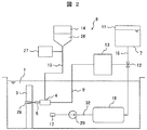
本実施例のアブレシブウォータジェット切断方法に用いられるアブレシブウォータジェット切断装置8を、図1、図2及び図3を用いて説明する。アブレシブウォータジェット切断装置8は、切断ヘッド4、ホウ酸水タンク11、高圧ポンプ13、アブレシブタンク14及び浄化装置18を備えている。   An abrasive water jet cutting device 8 used in the abrasive water jet cutting method of the present embodiment will be described with reference to FIGS. 1, 2, and 3. The abrasive water jet cutting device 8 includes a cutting head 4, a boric acid water tank 11, a high-pressure pump 13, an abrasive tank 14, and a purification device 18.

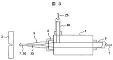
切断ヘッド4は、混合器6及び切断ノズル5を有する。切断ノズル5は、混合器6に取り付けられ、混合器6に連絡される噴射孔25を有する(図3参照)。ホウ酸水7が充填されたホウ酸水タンク11が、ホース16によって切替バルブ(三方弁)12に接続される。高圧ポンプ13が設けられたホース9が、切断ヘッド4に接続され、混合器6に連絡される。アブレシブである炭化ホウ素粒子26が充填されたアブレシブタンク14は、ホース10によって切断ヘッド4に接続される。ホース10は混合器6に連絡される。圧送空気供給装置27がホース10に接続される。吸引ポンプ(水中ポンプ)29及び浄化装置18が、吸引ノズル17に接続されて切替バルブ12に接続されるホース32に設けられる。   The cutting head 4 has a mixer 6 and a cutting nozzle 5. The cutting nozzle 5 is attached to the mixer 6 and has an injection hole 25 connected to the mixer 6 (see FIG. 3). A boric acid water tank 11 filled with boric acid water 7 is connected to a switching valve (three-way valve) 12 by a hose 16. A hose 9 provided with a high-pressure pump 13 is connected to the cutting head 4 and communicated with the mixer 6. The abrasive tank 14 filled with abrasive boron carbide particles 26 is connected to the cutting head 4 by the hose 10. The hose 10 is connected to the mixer 6. A pressurized air supply device 27 is connected to the hose 10. A suction pump (submersible pump) 29 and a purification device 18 are provided in a hose 32 connected to the suction nozzle 17 and connected to the switching valve 12.

アブレシブウォータジェット切断装置8を用いた本実施例のアブレシブウォータジェット切断方法を説明する。   The abrasive water jet cutting method of the present embodiment using the abrasive water jet cutting device 8 will be described.

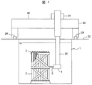
原子力プラントの定期検査期間中において原子炉圧力容器内の炉心から取り出された多数の使用済燃料集合体3が、原子炉建屋(図示せず)内の燃料プール1内に設置された複数の燃料貯蔵ラック2内にそれぞれ収納されている(図1参照)。燃料貯蔵ラック2は燃料プール1内に充填された冷却水中に配置されており、燃料貯蔵ラック2に収納された使用済燃料集合体3は、燃料プール1内に保管されている間、循環する冷却水によって冷却される。   A plurality of spent fuel assemblies 3 taken out from the core in the reactor pressure vessel during the periodic inspection period of the nuclear power plant are installed in the fuel pool 1 in the reactor building (not shown). Each is stored in the storage rack 2 (see FIG. 1). The fuel storage rack 2 is arranged in the cooling water filled in the fuel pool 1, and the spent fuel assembly 3 stored in the fuel storage rack 2 circulates while being stored in the fuel pool 1. Cooled by cooling water.

燃料貯蔵ラック2内に収納された使用済燃料集合体3の一部が、前述したように、何らかの原因でダメージを受けていることを想定する。   It is assumed that a part of the spent fuel assembly 3 stored in the fuel storage rack 2 is damaged for some reason as described above.

燃料貯蔵ラック2内のダメージを受けた使用済燃料集合体3を、燃料貯蔵ラック2から取り出すことができないので、アブレシブウォータジェット切断装置8を用いて、使用済燃料集合体3を収納している燃料貯蔵ラック2を燃料プール1内で切断する。燃料貯蔵ラック2の切断に際して、アブレシブウォータジェット切断装置8の切断ヘッド4が、燃料交換機20のマスト21に取り付けられる。ホウ酸水タンク11、高圧ポンプ13、アブレシブタンク14及び圧送空気供給装置27が、燃料プール1を取り囲んで原子炉建屋内に形成された運転床22上に設置される。吸引ノズル17、吸引ポンプ29及び浄化装置18が、燃料プール1内の冷却水中に配置される。   Since the spent fuel assembly 3 damaged in the fuel storage rack 2 cannot be taken out from the fuel storage rack 2, the spent fuel assembly 3 is stored using the abrasive water jet cutting device 8. The fuel storage rack 2 is cut in the fuel pool 1. When cutting the fuel storage rack 2, the cutting head 4 of the abrasive water jet cutting device 8 is attached to the mast 21 of the fuel exchanger 20. The boric acid water tank 11, the high-pressure pump 13, the abrasive tank 14, and the pressurized air supply device 27 are installed on an operation floor 22 that surrounds the fuel pool 1 and is formed in the reactor building. The suction nozzle 17, the suction pump 29 and the purification device 18 are arranged in the cooling water in the fuel pool 1.

燃料交換機20も運転床22上に配置されている。燃料交換機20は走行台車30及び横行台車31を有する。走行台車30は、燃料プール1を跨いで配置され、運転床22上に施設されたガイドレール24に沿って移動する。横行台車31は、走行台車30上に設置され、走行台車30上で走行台車30の移動方向と直交する方向に移動する。マスト31は、上下方向に移動可能に横行台車31に取り付けられる。   The fuel changer 20 is also disposed on the operation floor 22. The refueling machine 20 has a traveling carriage 30 and a traversing carriage 31. The traveling carriage 30 is arranged across the fuel pool 1 and moves along the guide rail 24 provided on the operation floor 22. The traversing carriage 31 is installed on the traveling carriage 30 and moves on the traveling carriage 30 in a direction orthogonal to the moving direction of the traveling carriage 30. The mast 31 is attached to the traverse carriage 31 so as to be movable in the vertical direction.

マスト21に取り付けられた切断ヘッド4が燃料プール1内の冷却水に浸漬された状態で、切断ノズル5が切断対象の燃料貯蔵ラック2の切断開始位置付近の真上に位置するように、走行台車30及び横行台車31をそれぞれ移動させ、水平方向における切断ノズル5の位置決めを行う。その後、マスト21を下降させて、切断ノズル5を、燃料貯蔵ラック2の上下方向における切断位置(例えば、燃料貯蔵ラック2の高さの1/2の位置)まで下降する。切断ノズル5が上下方向における切断位置まで下降したとき、マスト21の下降を停止する。その後、切断ノズル5は、燃料貯蔵ラック2の1つの側面に対向しながらその側面に沿って水平方向に移動される。この切断ノズル5の水平方向における移動は、例えば、横行台車31を移動させることによって行われ、燃料貯蔵ラック2を、使用済燃料集合体3を収納した状態で高さの1/2の位置で切断する。   In a state where the cutting head 4 attached to the mast 21 is immersed in the cooling water in the fuel pool 1, the traveling is performed so that the cutting nozzle 5 is located immediately above the cutting start position of the fuel storage rack 2 to be cut. The carriage 30 and the traversing carriage 31 are moved to position the cutting nozzle 5 in the horizontal direction. Thereafter, the mast 21 is lowered, and the cutting nozzle 5 is lowered to a cutting position in the vertical direction of the fuel storage rack 2 (for example, a position half the height of the fuel storage rack 2). When the cutting nozzle 5 is lowered to the cutting position in the vertical direction, the lowering of the mast 21 is stopped. Thereafter, the cutting nozzle 5 is moved in the horizontal direction along one side surface of the fuel storage rack 2 while facing the one side surface. The horizontal movement of the cutting nozzle 5 is performed, for example, by moving the traversing carriage 31, and the fuel storage rack 2 is placed at a position half the height with the spent fuel assembly 3 stored. Disconnect.

この燃料貯蔵ラック2及び使用済み燃料集合体3の切断は、切断ノズル5の噴射孔25からアブレシブを含む高圧水を噴射することによって行われる。噴射孔25からのこの高圧水の噴射は以下のようにして行われる。   The fuel storage rack 2 and the spent fuel assembly 3 are cut by injecting high-pressure water containing abrasive from the injection holes 25 of the cutting nozzle 5. The high-pressure water is injected from the injection hole 25 as follows.

切替弁12を操作してホース16とホース9を連絡し、高圧ポンプ13及び圧送空気供給装置27を駆動する。ホウ酸水タンク11内のホウ酸水7は、ホース16,9により高圧ポンプ13に導かれ、高圧ポンプ13によって約400MPaに昇圧されてホース9を通って切断ヘッド4の混合器6内に供給される。アブレシブタンク14内の炭化ホウ素粒子26が、圧送空気供給装置27からホース10内に供給される圧縮空気に随伴して、ホース10を通って切断ヘッド4の混合器6内に供給される。混合器6内ではホウ酸水7及び炭化ホウ素粒子26が混合され、炭化ホウ素粒子26を含むホウ酸水7の、高圧(約400MPa)の水流28が、噴射孔25から切断対象の燃料貯蔵ラック2に向かって噴射され、燃料貯蔵ラック2に衝突する。水流28に含まれるアブレシブである炭化ホウ素粒子26が高速で燃料貯蔵ラック2に衝突する。衝突する炭化ホウ素粒子26の作用により、炭化ホウ素粒子26が衝突する位置で、燃料貯蔵ラック2が切断される。燃料貯蔵ラック2内に収納された各使用済燃料集合体3も、燃料貯蔵ラック2の切断に併せて上下方向における同じ切断位置で切断される。   The switching valve 12 is operated to connect the hose 16 and the hose 9 to drive the high-pressure pump 13 and the pressurized air supply device 27. The boric acid water 7 in the boric acid water tank 11 is led to the high pressure pump 13 by the hoses 16 and 9, is pressurized to about 400 MPa by the high pressure pump 13, and is supplied to the mixer 6 of the cutting head 4 through the hose 9. Is done. Boron carbide particles 26 in the abrasive tank 14 are supplied into the mixer 6 of the cutting head 4 through the hose 10 along with the compressed air supplied into the hose 10 from the pressurized air supply device 27. In the mixer 6, the boric acid water 7 and the boron carbide particles 26 are mixed, and a high-pressure (about 400 MPa) water flow 28 of the boric acid water 7 containing the boron carbide particles 26 is supplied from the injection holes 25 to the fuel storage rack to be cut. 2 is injected and collides with the fuel storage rack 2. The abrasive boron carbide particles 26 contained in the water stream 28 collide with the fuel storage rack 2 at a high speed. The fuel storage rack 2 is cut at a position where the boron carbide particles 26 collide by the action of the colliding boron carbide particles 26. Each spent fuel assembly 3 housed in the fuel storage rack 2 is also cut at the same cutting position in the vertical direction in conjunction with the cutting of the fuel storage rack 2.

切断ノズル5の噴射孔25から、炭化ホウ素粒子26を含むホウ酸水7の高圧の水流28を噴射させながら、上記したように、横行台車31を移動させて切断ノズル5を、水平方向において、燃料貯蔵ラック2の1つの側面に沿って移動させる。上下方向の切断位置で、1つの燃料貯蔵ラック2の1つの側面に沿った切断ノズル5(炭化ホウ素粒子26を含む水流28を噴射)の水平方向における移動が終了したとき、その燃料貯蔵ラック2及びこの燃料貯蔵ラック2に収納された各使用済燃料集合体3の切断が終了する。   While spraying the high-pressure water stream 28 of the boric acid water 7 containing the boron carbide particles 26 from the injection holes 25 of the cutting nozzle 5, as described above, the traversing carriage 31 is moved so that the cutting nozzle 5 is moved in the horizontal direction. Move along one side of the fuel storage rack 2. When the horizontal movement of the cutting nozzle 5 (injecting the water stream 28 containing the boron carbide particles 26) along one side surface of one fuel storage rack 2 is completed at the vertical cutting position, the fuel storage rack 2 And the cutting | disconnection of each spent fuel assembly 3 accommodated in this fuel storage rack 2 is complete | finished.

切断ノズル5から噴射された水流28に含まれるホウ酸水7は、燃料プール1内の冷却水中に拡散する。本実施例では、燃料プール1内の冷却水のホウ酸の濃度を、分析装置を用いて測定する。ホウ酸濃度の測定は、所定の時間間隔で、燃料プール1内の冷却水を採取し、採取した冷却水を分析してこの冷却水に含まれるホウ酸濃度を測定する。測定された冷却水中のホウ酸濃度が、設定濃度以上になったとき、切替バルブ12を切り替えてホース32とホース9を連絡する。この設定濃度は、ホウ酸水タンク11から切断ノズル5にホウ酸水7を供給しなくても、燃料プール1内の冷却水に含まれる炭化ホウ素粒子26及びホウ酸水7として供給されたホウ酸によって冷却水中の核燃料物質により再臨界が生じることを防止することができるホウ酸の濃度である。   The boric acid water 7 contained in the water flow 28 injected from the cutting nozzle 5 diffuses into the cooling water in the fuel pool 1. In this embodiment, the concentration of boric acid in the cooling water in the fuel pool 1 is measured using an analyzer. The boric acid concentration is measured by collecting cooling water in the fuel pool 1 at predetermined time intervals, analyzing the collected cooling water, and measuring the boric acid concentration contained in the cooling water. When the measured boric acid concentration in the cooling water exceeds the set concentration, the switching valve 12 is switched to connect the hose 32 and the hose 9. This set concentration is obtained by supplying boron carbide particles 26 contained in the cooling water in the fuel pool 1 and boric acid water 7 supplied without boric acid water 7 from the boric acid water tank 11 to the cutting nozzle 5. This is the concentration of boric acid that can prevent acid from causing recriticality due to nuclear fuel material in the cooling water.

切替バルブ12でホース9とホース32が連絡されたとき、吸引ポンプ29が駆動されて燃料プール1内の、炭化ホウ素粒子26及びホウ酸を含む冷却水が、吸引ノズル17から吸引されてホース32内に流入する。ホース32内に流入した炭化ホウ素粒子26及びホウ酸を含む冷却水は、吸引ポンプ29で昇圧され、浄化装置18に導かれる。浄化装置18では、冷却水に含まれる炭化ホウ素粒子26、燃料貯蔵ラック2の切断粉及び燃料プール1内の冷却水に元々含まれているクラッド等が除去される。浄化装置18で浄化された、ホウ酸を含む冷却水は、ホース32及び9を経て高圧ポンプ13に導かれ、高圧ポンプ13により約400MPaに昇圧される。吸引ノズル17から吸引された、燃料プール1内の冷却水が、高圧ポンプ13に供給されているときには、ホウ酸水タンク11内のホウ酸水7が高圧ポンプ13に供給されることはない。   When the hose 9 and the hose 32 are communicated with each other through the switching valve 12, the suction pump 29 is driven, and the cooling water containing boron carbide particles 26 and boric acid in the fuel pool 1 is sucked from the suction nozzle 17 and is supplied to the hose 32. Flows in. The cooling water containing boron carbide particles 26 and boric acid flowing into the hose 32 is pressurized by the suction pump 29 and guided to the purification device 18. In the purification device 18, the boron carbide particles 26 contained in the cooling water, the cutting powder of the fuel storage rack 2, the cladding originally contained in the cooling water in the fuel pool 1 and the like are removed. The cooling water containing boric acid purified by the purification device 18 is guided to the high-pressure pump 13 through the hoses 32 and 9 and is pressurized to about 400 MPa by the high-pressure pump 13. When the cooling water in the fuel pool 1 sucked from the suction nozzle 17 is supplied to the high-pressure pump 13, the boric acid water 7 in the boric acid water tank 11 is not supplied to the high-pressure pump 13.

高圧ポンプ13で昇圧された高圧のホウ酸を含む冷却水は、切断ヘッド4の混合器6内に導かれ、ホース10を通して供給される炭化ホウ素粒子26と混合される。炭化ホウ素粒子26を含む高圧の冷却水は、混合器6から噴射孔25に導かれ、水流28となって切断対象の各燃料貯蔵ラック2に向かって噴射される。燃料貯蔵ラック2及びこの燃料貯蔵ラック2に収納された使用済燃料集合体3が、噴射されたその水流28に含まれる炭化ホウ素粒子26の作用により切断される。   Cooling water containing high-pressure boric acid pressurized by the high-pressure pump 13 is introduced into the mixer 6 of the cutting head 4 and mixed with boron carbide particles 26 supplied through the hose 10. The high-pressure cooling water containing the boron carbide particles 26 is guided from the mixer 6 to the injection hole 25 and becomes a water flow 28 and is injected toward each fuel storage rack 2 to be cut. The fuel storage rack 2 and the spent fuel assembly 3 housed in the fuel storage rack 2 are cut by the action of the boron carbide particles 26 contained in the injected water stream 28.

もし、吸引ノズル17から吸引された冷却水を含む水流28の噴射によって、燃料プール1内の冷却水に含まれるホウ酸の濃度が、燃料プール1内の冷却水に含まれる炭化ホウ素粒子26及びホウ酸によって冷却水中の核燃料物質により再臨界が生じることを防止することができるホウ酸の濃度よりも低下したときには、切替バルブ12を切り替えて、ホウ酸水タンク11内のホウ酸水7を混合器6に供給し、ホウ酸水7を含む水流28を、切断ノズル5から噴射する。   If the water stream 28 containing the cooling water sucked from the suction nozzle 17 is injected, the concentration of boric acid contained in the cooling water in the fuel pool 1 is changed to the boron carbide particles 26 contained in the cooling water in the fuel pool 1 and When the boric acid concentration is lower than the concentration of boric acid, which can prevent recriticality caused by nuclear fuel material in the cooling water, the switching valve 12 is switched to mix the boric acid water 7 in the boric acid water tank 11. The water stream 28 supplied to the vessel 6 and containing the boric acid water 7 is jetted from the cutting nozzle 5.

切断ノズル5から噴射される炭化ホウ素粒子26によって使用済燃料集合体3に含まれる燃料棒が切断されるとき、その切断位置で各燃料棒内に存在した核燃料物質が噴射された水流28によって、燃料プール1内の冷却水中に吹き飛ばされる。また、切断時における高速の水流28の燃料貯蔵ラック2および使用済燃料集合体3への衝突によって、使用済燃料集合体3に衝撃を与え、この使用済燃料集合体3が振動する。このため、燃料棒の切断箇所から燃料棒内の核燃料物質の一部が冷却水中に漏洩する。燃料貯蔵ラック2および使用済燃料集合体3の切断が進行すると、上記した理由により、使用済燃料集合体3から燃料プール1の冷却水に含まれる核燃料物質の濃度が増加する。冷却水中の核燃料物質の濃度が上昇すると、最悪の場合、核燃料物質の再臨界が生じる可能性を否定することができない。しかしながら、本実施例では、燃料貯蔵ラック2等の切断に用いるアブレシブとして中性子吸収材である炭化ホウ素粒子26が用いられており、切断ノズル5から噴射された炭化ホウ素粒子26は燃料プール1内の冷却水中に拡散して存在するので、上記の切断作業によって燃料プール1内の冷却水中の核燃料物質の濃度が増加しても、炭化ホウ素粒子26の作用により、再臨界を生じることを防止することができる。すなわち、燃料貯蔵ラック2および使用済燃料集合体3の切断によって冷却水中の核燃料物質の濃度が増加しても、未臨界の状態を維持することができる。   When the fuel rods included in the spent fuel assembly 3 are cut by the boron carbide particles 26 injected from the cutting nozzle 5, the water flow 28 in which the nuclear fuel material present in each fuel rod is injected at the cutting position, It is blown off into the cooling water in the fuel pool 1. Further, the spent fuel assembly 3 is impacted by the collision of the high-speed water flow 28 with the fuel storage rack 2 and the spent fuel assembly 3 at the time of cutting, and the spent fuel assembly 3 vibrates. For this reason, a part of the nuclear fuel material in the fuel rod leaks into the cooling water from the cut portion of the fuel rod. As the cutting of the fuel storage rack 2 and the spent fuel assembly 3 proceeds, the concentration of the nuclear fuel material contained in the cooling water of the fuel pool 1 from the spent fuel assembly 3 increases for the reason described above. When the concentration of nuclear fuel material in the cooling water increases, the possibility of recriticality of nuclear fuel material in the worst case cannot be denied. However, in the present embodiment, boron carbide particles 26 that are neutron absorbers are used as abrasives used for cutting the fuel storage rack 2 and the like, and the boron carbide particles 26 injected from the cutting nozzle 5 are contained in the fuel pool 1. Since it exists by diffusing in the cooling water, even if the concentration of the nuclear fuel material in the cooling water in the fuel pool 1 is increased by the above-described cutting operation, recriticality is prevented from occurring due to the action of the boron carbide particles 26. Can do. That is, even if the concentration of the nuclear fuel material in the cooling water is increased by cutting the fuel storage rack 2 and the spent fuel assembly 3, the subcritical state can be maintained.

また、本実施例では、切断時に切断ノズル5から噴射される水流28はホウ酸水7を含んでおり、切断ノズル5から噴射されたホウ酸水7も、燃料プール1内の冷却水中で拡散する。このホウ酸水7に含まれるホウ素(中性子吸収材)も、中性子を吸収するので、炭化ホウ素粒子26と同様に、冷却水に含まれる核燃料物質による再臨界を防止することができる。   Further, in this embodiment, the water flow 28 ejected from the cutting nozzle 5 at the time of cutting includes the boric acid water 7, and the boric acid water 7 ejected from the cutting nozzle 5 is also diffused in the cooling water in the fuel pool 1. To do. Since boron (neutron absorber) contained in the boric acid water 7 also absorbs neutrons, similarly to the boron carbide particles 26, recriticality due to the nuclear fuel material contained in the cooling water can be prevented.

本実施例は、未臨界の状態を維持して、燃料貯蔵ラック2及び燃料貯蔵ラック2に収納された使用済燃料集合体3を燃料プール1内の冷却水中でアブレシブウォータジェットを用いて切断することができる。アブレシブウォータジェットを用いて燃料貯蔵ラック2及び燃料貯蔵ラック2に収納された使用済燃料集合体3を切断するので、これらの切断を容易に行うことができる。   In this embodiment, the subcritical state is maintained, and the fuel storage rack 2 and the spent fuel assembly 3 accommodated in the fuel storage rack 2 are cut in the cooling water in the fuel pool 1 using an abrasive water jet. be able to. Since the fuel storage rack 2 and the spent fuel assembly 3 housed in the fuel storage rack 2 are cut using an abrasive water jet, the cutting can be easily performed.

本実施例は、切替バルブ12の切替えによってホウ酸を含む燃料プール1内の冷却水を水流28として切断ノズル5から噴射させて、燃料貯蔵ラック2等の切断に使用するので、この切断時に使用するホウ酸水タンク11内のホウ酸水7の使用量を低減することができる。   In this embodiment, the cooling water in the fuel pool 1 containing boric acid is injected from the cutting nozzle 5 as the water flow 28 by switching the switching valve 12 and used for cutting the fuel storage rack 2 and the like. The amount of the boric acid water 7 in the boric acid water tank 11 to be used can be reduced.

本実施例では、アブレシブとして、ホウ素化合物である炭化ホウ素粒子26以外に、ハフニウムの粒子を使用しても良い。炭化ホウ素粒子26およびハフニウムの粒子は、中性子吸収材の粒子である。   In this embodiment, hafnium particles may be used as the abrasive in addition to the boron carbide particles 26 that are boron compounds. The boron carbide particles 26 and the hafnium particles are neutron absorber particles.

本実施例は、燃料貯蔵ラック2内に、定期検査時に炉心から取り出されて寿命に到達していない燃料集合体が燃料貯蔵ラック2内に収納されている状態で、または炉心に装荷する前の燃焼度0GWd/tの燃料集合体が燃料貯蔵ラック2内に収納されている状態で、これらの燃料集合体が前述したようにダメージを受けている場合であっても、燃料貯蔵ラック及びこの燃料貯蔵ラック内の燃料集合体を切断することができる。   In this embodiment, in the fuel storage rack 2, a fuel assembly that has been removed from the core at the regular inspection and has not reached the end of its life is stored in the fuel storage rack 2 or before being loaded into the core. Even when a fuel assembly having a burnup of 0 GWd / t is stored in the fuel storage rack 2 and these fuel assemblies are damaged as described above, the fuel storage rack and the fuel assembly The fuel assembly in the storage rack can be cut.

後述の実施例2及び3でも、燃料貯蔵ラック2内に、定期検査時に炉心から取り出されて寿命に到達していない燃料集合体が燃料貯蔵ラック2内に収納されている状態で、または炉心に装荷する前の燃焼度0GWd/tの燃料集合体が燃料貯蔵ラック2内に収納されている状態で、燃料貯蔵ラック及びこの燃料貯蔵ラック内の燃料集合体を切断することができる。   Also in Examples 2 and 3 to be described later, in the fuel storage rack 2, a fuel assembly that has been removed from the core at the regular inspection and has not reached the end of its life is housed in the fuel storage rack 2 or in the core. The fuel storage rack and the fuel assembly in the fuel storage rack can be cut in a state where the fuel assembly having a burnup of 0 GWd / t before loading is stored in the fuel storage rack 2.

本発明の他の実施例である実施例2のアブレシブウォータジェット切断方法を、図4を用いて説明する。   An abrasive water jet cutting method according to embodiment 2, which is another embodiment of the present invention, will be described with reference to FIG.

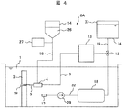
本実施例のアブレシブウォータジェット切断方法に用いられるアブレシブウォータジェット切断装置8Aは、実施例1に用いられるアブレシブウォータジェット切断装置8においてホウ酸水タンク11を水タンク33に替え、切替弁12、吸引ノズル17、浄化装置18、吸引ポンプ29ホース32を取り除いた構成を有する。中性子吸収材であるホウ素を含まない水34が充填された水タンク33は、ホース9によって高圧ポンプ13に接続される。アブレシブウォータジェット切断装置8Aの他の構成はアブレシブウォータジェット切断装置8と同じである。   The abrasive water jet cutting device 8A used in the abrasive water jet cutting method of the present embodiment replaces the boric acid water tank 11 with the water tank 33 in the abrasive water jet cutting device 8 used in the first embodiment, and switches the switching valve 12 and suction. The nozzle 17, the purification device 18, and the suction pump 29 have a configuration in which the hose 32 is removed. A water tank 33 filled with water 34 not containing boron, which is a neutron absorber, is connected to the high-pressure pump 13 by a hose 9. Other configurations of the abrasive water jet cutting device 8A are the same as those of the abrasive water jet cutting device 8.

本実施例では、燃料貯蔵ラック2及び燃料貯蔵ラック2に収納された使用済燃料集合体3の切断時に切断ノズル5から噴射される水流28は、炭化ホウ素粒子26、及び水タンク33からホース9を通って供給されたホウ素を含まない水34を含む水流である。   In this embodiment, when the fuel storage rack 2 and the spent fuel assembly 3 housed in the fuel storage rack 2 are cut, the water flow 28 injected from the cutting nozzle 5 is supplied from the boron carbide particles 26 and the water tank 33 to the hose 9. A water stream comprising boron-free water 34 fed through.

本実施例によれば、炭化ホウ素粒子26及び水34を含む水流28を燃料貯蔵ラック2に向かって噴射するので、水流28に含まれる炭化ホウ素粒子26の作用によって燃料貯蔵ラック2及び燃料貯蔵ラック2に収納された使用済燃料集合体3を切断することができる。水流28に含まれてその切断に使用された炭化ホウ素粒子26は、燃料プール1内の冷却水中に拡散する。このため、使用済燃料集合体3の切断によってその冷却水に含まれる核燃料物質の濃度が増加しても、冷却水中に拡散された炭化ボロン26の作用により、実施例1と同様に、再臨界を生じることを防止でき、未臨界の状態を保持することができる。   According to this embodiment, since the water stream 28 containing the boron carbide particles 26 and the water 34 is injected toward the fuel storage rack 2, the fuel storage rack 2 and the fuel storage rack are operated by the action of the boron carbide particles 26 contained in the water stream 28. The spent fuel assembly 3 housed in 2 can be cut. Boron carbide particles 26 contained in the water stream 28 and used for the cutting thereof diffuse into the cooling water in the fuel pool 1. For this reason, even if the concentration of the nuclear fuel material contained in the cooling water increases due to the cutting of the spent fuel assembly 3, the recriticality occurs in the same manner as in the first embodiment due to the action of boron carbide 26 diffused in the cooling water. Can be prevented, and a subcritical state can be maintained.

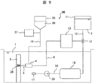
本発明の他の実施例である実施例3のアブレシブウォータジェット切断方法を、図5を用いて説明する。   An abrasive water jet cutting method according to embodiment 3, which is another embodiment of the present invention, will be described with reference to FIG.

本実施例のアブレシブウォータジェット切断方法に用いられるアブレシブウォータジェット切断装置8Bは、実施例1に用いられるアブレシブウォータジェット切断装置8においてアブレシブタンク14をアブレシブタンク35に替えた構成を有する。アブレシブタンク35はアブレシブとして炭化ホウ素粒子26の替りにアルミナ粒子36を充填している。ホース10がアブレシブタンク35に接続される。アブレシブウォータジェット切断装置8Bの他の構成はアブレシブウォータジェット切断装置8と同じである。   The abrasive water jet cutting device 8B used in the abrasive water jet cutting method of the present embodiment has a configuration in which the abrasive tank 14 is replaced with the abrasive tank 35 in the abrasive water jet cutting device 8 used in the first embodiment. The abrasive tank 35 is filled with alumina particles 36 instead of the boron carbide particles 26 as an abrasive. The hose 10 is connected to the abrasive tank 35. Other configurations of the abrasive water jet cutting device 8B are the same as those of the abrasive water jet cutting device 8.

本実施例では、燃料貯蔵ラック2及び燃料貯蔵ラック2に収納された使用済燃料集合体3の切断時に切断ノズル5から噴射される水流28は、アブレシブタンク35からホース10を通して切断ヘッド4に供給されたアルミナ粒子36、及びホース16及びホース9を通って供給されたホウ酸水7を含む水流である。本実施例では、切断ノズル5から噴射される水流28は、アブレッシブルとして、中性子吸収材(例えば、炭化ホウ素およびハフニウム)の粒子を含んでいなく、水流28に含まれるアルミナ粒子36も中性子吸収材を含んでいない。   In this embodiment, the water flow 28 injected from the cutting nozzle 5 when the fuel storage rack 2 and the spent fuel assembly 3 housed in the fuel storage rack 2 are cut is supplied from the abrasive tank 35 to the cutting head 4 through the hose 10. A water stream including the alumina particles 36 and the boric acid water 7 supplied through the hose 16 and the hose 9. In the present embodiment, the water stream 28 ejected from the cutting nozzle 5 is not abradable and does not contain particles of neutron absorbers (for example, boron carbide and hafnium), and the alumina particles 36 contained in the water stream 28 also absorb neutrons. Contains no material.

本実施例によれば、アルミナ粒子36及びホウ酸水7を含む水流28を燃料貯蔵ラック2に向かって噴射するので、水流28に含まれるアルミナ粒子36の作用によって燃料貯蔵ラック2及び燃料貯蔵ラック2に収納された使用済燃料集合体3を切断することができる。噴射された水流28に含まれたホウ酸は実施例1と同様に、燃料プール1内の冷却水中に拡散する。このため、使用済燃料集合体3の切断によってその冷却水に含まれる核燃料物質の濃度が増加しても、冷却水中に拡散されたホウ酸の作用により、実施例1と同様に、再臨界を生じることを防止でき、未臨界の状態を保持することができる。また、実施例1と同様に、吸引ノズル17から吸引されたホウ酸を含む冷却水を、水流28としてアルミナ粒子36と共に切断ノズル5から噴射することができる。このため、ホウ酸水タンク11内のホウ酸水7の使用量を低減することができる。   According to the present embodiment, since the water stream 28 containing the alumina particles 36 and the boric acid water 7 is injected toward the fuel storage rack 2, the fuel storage rack 2 and the fuel storage rack are operated by the action of the alumina particles 36 contained in the water stream 28. The spent fuel assembly 3 housed in 2 can be cut. The boric acid contained in the injected water stream 28 diffuses into the cooling water in the fuel pool 1 as in the first embodiment. For this reason, even if the concentration of the nuclear fuel material contained in the cooling water increases due to the cutting of the spent fuel assembly 3, recriticality is caused in the same manner as in Example 1 due to the action of boric acid diffused in the cooling water. This can be prevented and a subcritical state can be maintained. As in the first embodiment, the cooling water containing boric acid sucked from the suction nozzle 17 can be jetted from the cutting nozzle 5 together with the alumina particles 36 as the water flow 28. For this reason, the usage-amount of the boric-acid water 7 in the boric-acid water tank 11 can be reduced.

実施例3では、アルミナ粒子36の替りに、アブレシブとして鋳鋼の粒子を用いても良い。アルミナ粒子36及び鋳鋼の粒子はホウ素を含んでいないアブレシブである。   In Example 3, instead of the alumina particles 36, particles of cast steel may be used as abrasives. The alumina particles 36 and the cast steel particles are abrasives that do not contain boron.

1…燃料プール、2…燃料貯蔵ラック、3…使用済燃料集合体、4…切断ヘッド、5…切断ノズル、6…混合器、7…ホウ酸水、8,8A,8B…アブレシブウォータジェット切断装置、9,10,16,32…ホース、11…ホウ酸水タンク、12…切替バルブ、13…高圧ポンプ、14,35…アブレシブタンク、17…吸引ノズル、18…浄化装置、20…燃料交換機、21…マスト、22…運転床、26…炭化ホウ素粒子、27…圧送空気供給装置、33…水タンク、34…水、36…アルミナ粒子。   DESCRIPTION OF SYMBOLS 1 ... Fuel pool, 2 ... Fuel storage rack, 3 ... Used fuel assembly, 4 ... Cutting head, 5 ... Cutting nozzle, 6 ... Mixer, 7 ... Boric acid water, 8, 8A, 8B ... Abrasive water jet cutting Device: 9, 10, 16, 32 ... hose, 11 ... boric acid water tank, 12 ... switching valve, 13 ... high pressure pump, 14, 35 ... abrasive tank, 17 ... suction nozzle, 18 ... purification device, 20 ... fuel changer , 21 ... mast, 22 ... operating bed, 26 ... boron carbide particles, 27 ... pressurized air supply device, 33 ... water tank, 34 ... water, 36 ... alumina particles.

Claims (11)

水中に配置された、燃料集合体を収納する燃料ラックに向かってアブレシブルである中性子吸収材の粒子を含む水流をノズルから噴射させ、噴射された前記中性子吸収材の粒子により前記燃料ラック及び前記燃料集合体を切断するアブレシブウォータジェット切断方法。   A water stream containing neutron absorber particles that are abradable toward a fuel rack that houses a fuel assembly disposed in water is injected from a nozzle, and the fuel rack and the fuel are injected by the injected neutron absorber particles. Abrasive water jet cutting method for cutting an assembly. 前記中性子吸収材の粒子が、ホウ素化合物の粒子およびハフニウムの粒子のいずれかである請求項1に記載のアブレシブウォータジェット切断方法。   2. The abrasive water jet cutting method according to claim 1, wherein the particles of the neutron absorber are either boron compound particles or hafnium particles. 前記ノズルから噴射される前記水流が中性子吸収材を含む水溶液を含んでいる請求項1または2に記載のアブレシブウォータジェット切断方法。   The abrasive water jet cutting method according to claim 1 or 2, wherein the water stream ejected from the nozzle includes an aqueous solution containing a neutron absorber. 前記中性子吸収材を含む水溶液がこの水溶液を蓄えたタンクから前記ノズルに供給される請求項3に記載のアブレシブウォータジェット切断方法。   4. The abrasive water jet cutting method according to claim 3, wherein the aqueous solution containing the neutron absorber is supplied to the nozzle from a tank in which the aqueous solution is stored. 前記ノズルに供給される前記中性子吸収材を含む水溶液が、前記燃料貯蔵ラックの周囲に存在する、前記中性子吸収材を含む前記水であり、前記タンクから前記ノズルへの前記中性子吸収材を含む水溶液の供給が停止される請求項4に記載のアブレシブウォータジェット切断方法。   The aqueous solution containing the neutron absorber supplied to the nozzle is the water containing the neutron absorber present around the fuel storage rack, and the aqueous solution containing the neutron absorber from the tank to the nozzle The abrasive water jet cutting method according to claim 4, wherein the supply of water is stopped. 前記中性子吸収材を含む水溶液がホウ素を含む水溶液である請求項3ないし5のいずれか1項に記載のアブレシブウォータジェット切断方法。   The abrasive water jet cutting method according to claim 3, wherein the aqueous solution containing the neutron absorber is an aqueous solution containing boron. 水中に配置された、燃料集合体を収納する燃料ラックに向かって中性子吸収材を含まないアブレシブ及び中性子吸収材を含む水溶液を含む水流をノズルから噴射させ、噴射された前記アブレシブにより前記燃料ラック及び前記燃料集合体を切断するアブレシブウォータジェット切断方法。   A water stream containing an abrasive containing no neutron absorbing material and an aqueous solution containing a neutron absorbing material is jetted from a nozzle toward a fuel rack containing a fuel assembly disposed in water, and the fuel rack and An abrasive water jet cutting method for cutting the fuel assembly. 前記中性子吸収材を含む水溶液がホウ素を含む水溶液である請求項7に記載のアブレシブウォータジェット切断方法。   The abrasive water jet cutting method according to claim 7, wherein the aqueous solution containing the neutron absorber is an aqueous solution containing boron. 中性子吸収材の粒子が充填された第1タンクと、水が充填された第2タンクと、前記水を昇圧するポンプと、前記第1タンク内の前記中性子吸収材の粒子及び前記ポンプで昇圧された前記水を混合された状態で噴射するノズルとを備えたことを特徴とするアブレシブウォータジェット切断装置。   A first tank filled with particles of a neutron absorber, a second tank filled with water, a pump for boosting the water, the particles of the neutron absorber in the first tank and the pump An abrasive water jet cutting apparatus comprising: a nozzle that injects the water in a mixed state. 前記第2タンクが、中性子吸収材を含む前記水を充填した第2タンクである請求項9に記載のアブレシブウォータジェット切断装置。   The abrasive water jet cutting apparatus according to claim 9, wherein the second tank is a second tank filled with the water containing a neutron absorber. 中性子吸収材を含まないアブレッシブが充填された第1タンクと、中性子吸収材を含む水溶液が充填された第2タンクと、前記水溶液を昇圧するポンプと、前記第1タンク内の前記アブレシブ及び前記ポンプで昇圧された前記水溶液を混合された状態で噴射するノズルとを備えたことを特徴とするアブレシブウォータジェット切断装置。   A first tank filled with an abrasive that does not contain a neutron absorber, a second tank filled with an aqueous solution containing a neutron absorber, a pump for boosting the aqueous solution, the abrasive in the first tank, and the pump An abrasive water jet cutting apparatus, comprising: a nozzle that injects the aqueous solution whose pressure has been increased in a mixed state.
JP2011121334A 2011-05-31 2011-05-31 Abrasive water jet cutting method and apparatus Active JP5497691B2 (en)

Priority Applications (1)

Application Number Priority Date Filing Date Title
JP2011121334A JP5497691B2 (en) 2011-05-31 2011-05-31 Abrasive water jet cutting method and apparatus

Applications Claiming Priority (1)

Application Number Priority Date Filing Date Title
JP2011121334A JP5497691B2 (en) 2011-05-31 2011-05-31 Abrasive water jet cutting method and apparatus

Publications (2)

Publication Number Publication Date
JP2012247384A true JP2012247384A (en) 2012-12-13
JP5497691B2 JP5497691B2 (en) 2014-05-21

Family

ID=47467931

Family Applications (1)

Application Number Title Priority Date Filing Date
JP2011121334A Active JP5497691B2 (en) 2011-05-31 2011-05-31 Abrasive water jet cutting method and apparatus

Country Status (1)

Country Link
JP (1) JP5497691B2 (en)

Cited By (2)

* Cited by examiner, † Cited by third party
Publication number Priority date Publication date Assignee Title
JP2015007596A (en) * 2013-06-26 2015-01-15 株式会社東芝 Molten fuel cutting device and cutting method thereof
JP2023136523A (en) * 2022-03-17 2023-09-29 東京電力ホールディングス株式会社 Pulverization device

Citations (9)

* Cited by examiner, † Cited by third party
Publication number Priority date Publication date Assignee Title
JPS6145084A (en) * 1984-08-10 1986-03-04 鹿島建設株式会社 Cutting method by abbrasive jet
JPH032697A (en) * 1989-05-31 1991-01-09 Science & Tech Agency Fluidized grinding decontamination method and apparatus for removing radioactive corrosion product and contaminant strongly stuck to inner surface of piping by fine abrasive
JPH04121695A (en) * 1990-09-13 1992-04-22 Ohbayashi Corp Processing of highly radioactivated concrete
JPH0784094A (en) * 1993-09-13 1995-03-31 Kawasaki Heavy Ind Ltd Underwater cutting equipment for highly radioactive solid waste
JPH09502664A (en) * 1993-08-27 1997-03-18 イクストゥルードゥ ホーン コーポレーション Cutting of abrasives by jet stream
JPH10132989A (en) * 1996-10-31 1998-05-22 Mitsubishi Heavy Ind Ltd Solution tank
JP2009133701A (en) * 2007-11-30 2009-06-18 Toshiba Corp Criticality safety management method for continuous dissolution tank in reprocessing facility
WO2010036926A2 (en) * 2008-09-25 2010-04-01 Strategic Resource Optimization, Inc. Electrolytic system and method for enhanced radiological, nuclear, and industrial decontamination
JP2010223923A (en) * 2009-03-25 2010-10-07 Kawasaki Plant Systems Ltd Underwater volume reduction system for spent control rod

Patent Citations (10)

* Cited by examiner, † Cited by third party
Publication number Priority date Publication date Assignee Title
JPS6145084A (en) * 1984-08-10 1986-03-04 鹿島建設株式会社 Cutting method by abbrasive jet
JPH032697A (en) * 1989-05-31 1991-01-09 Science & Tech Agency Fluidized grinding decontamination method and apparatus for removing radioactive corrosion product and contaminant strongly stuck to inner surface of piping by fine abrasive
JPH04121695A (en) * 1990-09-13 1992-04-22 Ohbayashi Corp Processing of highly radioactivated concrete
JPH09502664A (en) * 1993-08-27 1997-03-18 イクストゥルードゥ ホーン コーポレーション Cutting of abrasives by jet stream
JPH0784094A (en) * 1993-09-13 1995-03-31 Kawasaki Heavy Ind Ltd Underwater cutting equipment for highly radioactive solid waste
JPH10132989A (en) * 1996-10-31 1998-05-22 Mitsubishi Heavy Ind Ltd Solution tank
JP2009133701A (en) * 2007-11-30 2009-06-18 Toshiba Corp Criticality safety management method for continuous dissolution tank in reprocessing facility
WO2010036926A2 (en) * 2008-09-25 2010-04-01 Strategic Resource Optimization, Inc. Electrolytic system and method for enhanced radiological, nuclear, and industrial decontamination
JP2012503547A (en) * 2008-09-25 2012-02-09 ストラテジック リソース オプティミゼーション, インコーポレイテッド Electrolysis system and method for enhanced radiation, nuclear and industrial contaminants
JP2010223923A (en) * 2009-03-25 2010-10-07 Kawasaki Plant Systems Ltd Underwater volume reduction system for spent control rod

Cited By (3)

* Cited by examiner, † Cited by third party
Publication number Priority date Publication date Assignee Title
JP2015007596A (en) * 2013-06-26 2015-01-15 株式会社東芝 Molten fuel cutting device and cutting method thereof
JP2023136523A (en) * 2022-03-17 2023-09-29 東京電力ホールディングス株式会社 Pulverization device
JP7813005B2 (en) 2022-03-17 2026-02-12 東京電力ホールディングス株式会社 Crushing equipment

Also Published As

Publication number Publication date
JP5497691B2 (en) 2014-05-21

Similar Documents

Publication Publication Date Title
KR101063132B1 (en) Chemical decontamination apparatus and decontamination method therein
US6533640B1 (en) Ultra high pressure abrasive waterjet cutting apparatus
JP5843492B2 (en) Radiation shielding method and structure processing method
KR102181790B1 (en) Apparatus and method for removing the upper internals from a nuclear reactor pressurized vessel
JP5497691B2 (en) Abrasive water jet cutting method and apparatus
CN104475974B (en) Wet method underwater laser soldering test equipment and technique
JP6125261B2 (en) Water jet peening compressive residual stress test method
JP6226646B2 (en) Reactor pressure vessel decontamination method and decontamination system thereof
KR20190029803A (en) Method for dismantling Reactor Vessel
US6587535B1 (en) Jet pump slip joint labyrinth seal method
KR20150099812A (en) Water jet peening device and method for executing water jet peening
KR102069520B1 (en) Eco-friendly dry wire saw cutting system and Drive method of the Same
EP2940695B1 (en) Systems for reducing surface deposition and contamination
KR102025149B1 (en) Nozzle cutting device in reactor vessel
KR20250107049A (en) Apparatus for decommissioning heavy water reactor facilities and method for decommissioning heavy water reactor facilities
KR101209180B1 (en) Reactor vessel for minimizing ecc bypass
JP2007212293A (en) Chemical decontamination apparatus and decontamination method thereof
JP2014044084A (en) Neutron absorber, and processing method of molten fuel
KR102751727B1 (en) Cleaing apparatus for nozzle of reactor vessel head
JP5752619B2 (en) Apparatus and method for cleaning tip of control rod drive mechanism
JP2012091199A (en) Preventive maintenance method for pipe welded part
US20140233689A1 (en) Water Jet Peening Apparatus and Water Jet Peening Method
JP4875673B2 (en) Strainer for reactor containment
JP2007232531A (en) In-furnace chemical decontamination apparatus and decontamination method thereof
CN223288603U (en) A pressurized water reactor nuclear fuel assembly unloading spray cleaning device

Legal Events

Date Code Title Description
A621 Written request for application examination

Free format text: JAPANESE INTERMEDIATE CODE: A621

Effective date: 20130621

A977 Report on retrieval

Free format text: JAPANESE INTERMEDIATE CODE: A971007

Effective date: 20140127

TRDD Decision of grant or rejection written
A01 Written decision to grant a patent or to grant a registration (utility model)

Free format text: JAPANESE INTERMEDIATE CODE: A01

Effective date: 20140225

A61 First payment of annual fees (during grant procedure)

Free format text: JAPANESE INTERMEDIATE CODE: A61

Effective date: 20140306

R150 Certificate of patent or registration of utility model

Ref document number: 5497691

Country of ref document: JP

Free format text: JAPANESE INTERMEDIATE CODE: R150

S533 Written request for registration of change of name

Free format text: JAPANESE INTERMEDIATE CODE: R313533

R350 Written notification of registration of transfer

Free format text: JAPANESE INTERMEDIATE CODE: R350