JP2012247609A - Lens unit - Google Patents
Lens unit Download PDFInfo
- Publication number
- JP2012247609A JP2012247609A JP2011118977A JP2011118977A JP2012247609A JP 2012247609 A JP2012247609 A JP 2012247609A JP 2011118977 A JP2011118977 A JP 2011118977A JP 2011118977 A JP2011118977 A JP 2011118977A JP 2012247609 A JP2012247609 A JP 2012247609A
- Authority
- JP
- Japan
- Prior art keywords
- lens
- laser
- lens holder
- holder
- absorbing means
- Prior art date
- Legal status (The legal status is an assumption and is not a legal conclusion. Google has not performed a legal analysis and makes no representation as to the accuracy of the status listed.)
- Pending
Links
- 229920000089 Cyclic olefin copolymer Polymers 0.000 claims abstract description 9
- 239000000463 material Substances 0.000 claims abstract description 9
- 239000010419 fine particle Substances 0.000 claims description 10
- 239000002952 polymeric resin Substances 0.000 claims description 7
- 239000003086 colorant Substances 0.000 claims description 5
- 238000000034 method Methods 0.000 abstract description 10
- 238000003466 welding Methods 0.000 abstract description 10
- 229920005989 resin Polymers 0.000 abstract description 3
- 239000011347 resin Substances 0.000 abstract description 3
- 238000006073 displacement reaction Methods 0.000 abstract 1
- 239000000853 adhesive Substances 0.000 description 4
- 230000001070 adhesive effect Effects 0.000 description 4
- OKTJSMMVPCPJKN-UHFFFAOYSA-N Carbon Chemical compound [C] OKTJSMMVPCPJKN-UHFFFAOYSA-N 0.000 description 2
- 238000010521 absorption reaction Methods 0.000 description 2
- 229910052799 carbon Inorganic materials 0.000 description 2
- 230000000694 effects Effects 0.000 description 2
- 239000004033 plastic Substances 0.000 description 2
- 239000004417 polycarbonate Substances 0.000 description 2
- 229920000515 polycarbonate Polymers 0.000 description 2
- 239000004823 Reactive adhesive Substances 0.000 description 1
- 238000004040 coloring Methods 0.000 description 1
- 230000001678 irradiating effect Effects 0.000 description 1
- 238000002844 melting Methods 0.000 description 1
- 230000008018 melting Effects 0.000 description 1
- 239000012528 membrane Substances 0.000 description 1
- JHJNPOSPVGRIAN-SFHVURJKSA-N n-[3-[(1s)-1-[[6-(3,4-dimethoxyphenyl)pyrazin-2-yl]amino]ethyl]phenyl]-5-methylpyridine-3-carboxamide Chemical compound C1=C(OC)C(OC)=CC=C1C1=CN=CC(N[C@@H](C)C=2C=C(NC(=O)C=3C=C(C)C=NC=3)C=CC=2)=N1 JHJNPOSPVGRIAN-SFHVURJKSA-N 0.000 description 1
- 239000002861 polymer material Substances 0.000 description 1
- 238000002834 transmittance Methods 0.000 description 1
Images

Landscapes
- Lens Barrels (AREA)
Abstract
Description
本発明は、レンズとレンズホルダとを有するレンズユニットの溶着技術に関し、詳しくは線膨張係数の違いにより生じる寸法ずれが大きな障害となる精密部品におけるレンズとレンズホルダとの溶着技術に関する。 The present invention relates to a technique for welding a lens unit having a lens and a lens holder, and more particularly, to a technique for welding a lens and a lens holder in a precision component in which a dimensional shift caused by a difference in linear expansion coefficient is a major obstacle.
プラスチックレンズを利用する一般的なレンズホルダはポリカーボネートで構成されており、このレンズホルダとプラスチックレンズとを固定する方法として、接着剤による固着や紫外線反応性接着剤を塗布後に紫外線を照射して固着する接着によるもの、熱かしめにより固着するもの、高出力のレーザによりレンズとレンズホルダの一部を溶融させ溶融部分を相溶させることによって固定するレーザ溶着によるもの等が挙げられる。そして、レーザ溶着による技術として、例えば「特許文献1」あるいは「特許文献2」に開示されたものが知られている。
A general lens holder using a plastic lens is made of polycarbonate. As a method of fixing the lens holder and the plastic lens, fixing with an adhesive or applying UV-reactive adhesive and then irradiating with ultraviolet rays is performed. For example, by fixing by heat caulking, by laser welding for fixing by melting a part of the lens and the lens holder with a high-power laser and mixing the melted part. As a technique by laser welding, for example, one disclosed in “Patent Document 1” or “
しかし、接着による固定方法では、レンズやレンズホルダの材質によっては接着剤による固着が十分に機能せず、接着力が不十分であることにより剥離してしまう場合がある。熱かしめによる固定方法では、熱で固定するためにレンズとレンズホルダとの線膨張係数の違いにより寸法ずれが生じる虞がある。レーザ溶着による固定方法では、極性樹脂であるポリカーボネートと非極性樹脂であるシクロオレフィンポリマ系材料(以下、COPと称する)のように相溶性のない材質同士では十分な接着力を得ることができない場合がある。また、これ等の問題点を解決するためにレーザ溶着と接着剤とを組み合わせること等が必要となり、工程の増加等によりコストアップが問題となる他、レンズ及びレンズホルダの材料選択が限定的とならざるを得ないという問題点がある。 However, in the fixing method by adhesion, depending on the material of the lens or the lens holder, the fixing by the adhesive may not function sufficiently, and the adhesive may be peeled off due to insufficient adhesion. In the fixing method by heat caulking, there is a possibility that dimensional deviation occurs due to a difference in linear expansion coefficient between the lens and the lens holder in order to fix with heat. When the fixing method by laser welding cannot provide sufficient adhesion between materials that are not compatible, such as polycarbonate, which is a polar resin, and cycloolefin polymer material, which is a nonpolar resin (hereinafter referred to as COP). There is. In addition, in order to solve these problems, it is necessary to combine laser welding and an adhesive, etc., and there is a problem of cost increase due to an increase in processes, etc., and selection of materials for lenses and lens holders is limited. There is a problem that it must be.
本発明は上述の問題点を解決し、線膨張係数の違いにより生じる寸法ずれの発生を防止でき、レンズとレンズホルダとを精度よく溶着することが可能な溶着技術の提供を目的とする。 SUMMARY OF THE INVENTION An object of the present invention is to solve the above-mentioned problems, to provide a welding technique that can prevent the occurrence of dimensional deviation caused by a difference in linear expansion coefficient and can weld a lens and a lens holder with high accuracy.
請求項1記載の発明は、レンズ及び前記レンズを保持するレンズホルダを有するレンズユニットにおいて、前記レンズ及び前記レンズホルダは共にシクロオレフィンポリマ系の樹脂材料によって構成されると共に、前記レンズと前記レンズホルダとの接触部の少なくとも一方にはレーザを吸収させるレーザ吸収手段が設けられ、前記レンズと前記レンズホルダとは前記レーザ吸収手段に吸収されるレーザによって溶着されることを特徴とする。 According to a first aspect of the present invention, in the lens unit having a lens and a lens holder for holding the lens, the lens and the lens holder are both made of a cycloolefin polymer resin material, and the lens and the lens holder At least one of the contact portions is provided with laser absorbing means for absorbing laser, and the lens and the lens holder are welded by the laser absorbed by the laser absorbing means.
請求項2記載の発明は、請求項1記載のレンズユニットにおいて、さらに前記レーザ吸収手段は前記レーザを透過させない非透過性を有することを特徴とする。 According to a second aspect of the present invention, in the lens unit according to the first aspect, the laser absorbing means further has non-transmissibility that does not transmit the laser.
請求項3記載の発明は、請求項2記載のレンズユニットにおいて、さらに前記レーザ吸収手段は前記レンズまたは前記レンズホルダの少なくとも一方を着色する着色剤であることを特徴とする。 According to a third aspect of the present invention, in the lens unit according to the second aspect, the laser absorbing means is a colorant that colors at least one of the lens or the lens holder.
請求項4記載の発明は、請求項2記載のレンズユニットにおいて、さらに前記レーザ吸収手段は前記レンズまたは前記レンズホルダの少なくとも一方に設けられた遮光性を有する微細粒子であることを特徴とする。 According to a fourth aspect of the present invention, in the lens unit according to the second aspect, the laser absorbing means is a fine particle having a light shielding property provided on at least one of the lens or the lens holder.
請求項5記載の発明は、請求項2記載のレンズユニットにおいて、さらに前記レーザ吸収手段は前記レンズまたは前記レンズホルダの少なくとも一方に設けられた膜であることを特徴とする。 According to a fifth aspect of the present invention, in the lens unit according to the second aspect, the laser absorbing means is a film provided on at least one of the lens or the lens holder.
本発明によれば、線膨張係数の違いに起因する寸法ずれが発生せずに温度環境変化に強い精密部品を構成できると共に、レンズとレンズホルダとを所定の強度で精度よく固着することができる。 According to the present invention, it is possible to configure a precision component that is resistant to changes in temperature environment without causing a dimensional shift due to a difference in linear expansion coefficient, and it is possible to fix the lens and the lens holder with a predetermined strength with high accuracy. .
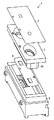
図1は、本発明の第1の実施形態を採用したレンズユニットを示している。同図においてレンズユニット1は、レンズであるレンズ部2aを有するレンズ構造体2と、レンズ構造体2を保持するレンズホルダ3と、レンズ構造体2とレンズホルダ3との間に挟まれる遮光シート4と、遮光シート4とによってレンズ構造体2を挟み込む遮光シート5等を有している。
FIG. 1 shows a lens unit employing the first embodiment of the present invention. In the figure, a lens unit 1 includes a
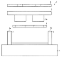
シクロオレフィンポリマ系樹脂(例えば日本ゼオン社製ZEONEX)からなるレンズ構造体2は、図2に示すように、遮光シート4を挟んだ状態でレンズ構造体2と同じ材質であるシクロオレフィンポリマ系樹脂からなるレンズホルダ3に装着される。ここで、レンズホルダ3のレンズ構造体2の両端部と対応する位置にはそれぞれ突出した載置部3aが形成されており、各載置部3a上にレンズ構造体2の両端部がそれぞれ載置された状態でレンズ構造体2とレンズホルダ3とがレーザによって溶着されて両者が固定される。これにより、レンズ部2aを有するレンズ構造体2とこれを保持するレンズホルダ3とが同じ材質であるため、レンズ構造体2とレンズホルダ3との線膨張係数の違いに起因する寸法ずれが発生せず、温度環境変化に強い精密部品を構成することが可能となる。
As shown in FIG. 2, the
しかし、一般的にシクロオレフィンポリマ系樹脂は無色透明であるためにレーザを吸収することができず、無色透明なシクロオレフィンポリマ系樹脂同士をレーザにより溶着することはできなかった。そこで本発明では、図2に示すように各載置部3aの近傍に位置するレンズホルダ3に、シクロオレフィンポリマ系樹脂に着色を行う着色剤であるカーボンを含有させ、レーザを吸収させるレーザ吸収手段6を形成している。レンズホルダ3に含有されるカーボンは1〜3重量%程度であり、レーザの透過率が十分な溶着を行うに足りる程度となるように設定されている。
However, since the cycloolefin polymer resin is generally colorless and transparent, it cannot absorb laser, and the colorless and transparent cycloolefin polymer resin cannot be welded together by laser. Therefore, in the present invention, as shown in FIG. 2, the
上述の構成により、線膨張係数の違いに起因する寸法ずれが発生せずに温度環境変化に強い精密部品を構成できると共に、レンズ構造体2とレンズホルダ3とを所定の強度で精度よく固着することができる。なお、上記実施形態ではレンズホルダ3側にレーザ吸収手段6を設ける構成としたが、レンズ構造体2側にレーザ吸収手段6を設ける構成、レンズ構造体2とレンズホルダ3との双方にレーザ吸収手段6を設ける構成としてもよい。
With the above-described configuration, it is possible to configure a precision component that is resistant to changes in temperature environment without causing a dimensional shift due to a difference in linear expansion coefficient, and to fix the
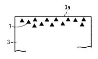
図3は、本発明の第2の実施形態を示している。この第2の実施形態は第1の実施形態と比較すると、載置部3aの下方にレーザ吸収手段として機能する複数の遮光性を有する微細粒子7を有する点においてのみ相違しており、他の構成は同一である。微細粒子7としては遮光性を有するものであればどんな材質のものでも使用可能であり、その配設位置は図4に示すように載置部3aの表面に近いほど吸収した際のレーザの熱が載置部3aの表面に現れやすく溶着が容易に行われるが、載置部3aの表面に限られることはない。本実施形態では微細粒子7をレンズホルダ3側に設ける構成を示したが、レンズ構造体2側に微細粒子7を設ける構成、レンズ構造体2とレンズホルダ3との双方に微細粒子7を設ける構成としてもよい。この構成により、第1の実施形態と同様の作用効果を得ることができる。
FIG. 3 shows a second embodiment of the present invention. This second embodiment is different from the first embodiment only in that it has a plurality of light-shielding
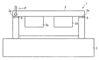
図5は、本発明の第3の実施形態を示している。この第3の実施形態は第1の実施形態と比較すると、載置部3aの上方にレーザ吸収手段として機能する膜8を有する点においてのみ相違しており、他の構成は同一である。なお、図5では各遮光シート4,5の図示を省略している。膜8としてはレーザを透過させない非透過性を有するものであればどのようなものでも使用可能であり、本実施形態ではクリアウェル(日本ジェネティクス(株)製)を使用してこれを載置部3a上に接着等の手段によって固着している。この構成により、第1の実施形態と同様の作用効果を得ることができる。
FIG. 5 shows a third embodiment of the present invention. Compared with the first embodiment, the third embodiment is different only in that it has a film 8 that functions as a laser absorbing means above the
1 レンズユニット
2 レンズ構造体
2a レンズ(レンズ部)
3 レンズホルダ
3a 載置部
6 レーザ吸収手段
7 遮光性を有する微細粒子
8 膜
DESCRIPTION OF SYMBOLS 1
DESCRIPTION OF
Claims (5)
前記レンズ及び前記レンズホルダは共にシクロオレフィンポリマ系の樹脂材料によって構成されると共に、前記レンズと前記レンズホルダとの接触部の少なくとも一方にはレーザを吸収させるレーザ吸収手段が設けられ、前記レンズと前記レンズホルダとは前記レーザ吸収手段に吸収されるレーザによって溶着されることを特徴とするレンズユニット。 In a lens unit having a lens and a lens holder for holding the lens,
The lens and the lens holder are both made of a cycloolefin polymer resin material, and at least one of the contact portions between the lens and the lens holder is provided with laser absorbing means for absorbing laser, The lens unit is welded by a laser absorbed by the laser absorbing means.
前記レーザ吸収手段は前記レーザを透過させない非透過性を有することを特徴とするレンズユニット。 The lens unit according to claim 1, wherein
The lens unit according to claim 1, wherein the laser absorbing means has non-transmissibility that does not transmit the laser.
前記レーザ吸収手段は前記レンズまたは前記レンズホルダの少なくとも一方を着色する着色剤であることを特徴とするレンズユニット。 The lens unit according to claim 2,
The lens unit, wherein the laser absorbing means is a colorant that colors at least one of the lens or the lens holder.
前記レーザ吸収手段は前記レンズまたは前記レンズホルダの少なくとも一方に設けられた遮光性を有する微細粒子であることを特徴とするレンズユニット。 The lens unit according to claim 2,
The lens unit according to claim 1, wherein the laser absorbing means is a light-shielding fine particle provided in at least one of the lens or the lens holder.
前記レーザ吸収手段は前記レンズまたは前記レンズホルダの少なくとも一方に設けられた膜であることを特徴とするレンズユニット。 The lens unit according to claim 2,
The lens unit, wherein the laser absorbing means is a film provided on at least one of the lens and the lens holder.
Priority Applications (1)
| Application Number | Priority Date | Filing Date | Title |
|---|---|---|---|
| JP2011118977A JP2012247609A (en) | 2011-05-27 | 2011-05-27 | Lens unit |
Applications Claiming Priority (1)
| Application Number | Priority Date | Filing Date | Title |
|---|---|---|---|
| JP2011118977A JP2012247609A (en) | 2011-05-27 | 2011-05-27 | Lens unit |
Publications (1)
| Publication Number | Publication Date |
|---|---|
| JP2012247609A true JP2012247609A (en) | 2012-12-13 |
Family
ID=47468099
Family Applications (1)
| Application Number | Title | Priority Date | Filing Date |
|---|---|---|---|
| JP2011118977A Pending JP2012247609A (en) | 2011-05-27 | 2011-05-27 | Lens unit |
Country Status (1)
| Country | Link |
|---|---|
| JP (1) | JP2012247609A (en) |
Citations (3)
| Publication number | Priority date | Publication date | Assignee | Title |
|---|---|---|---|---|
| JP2006235123A (en) * | 2005-02-23 | 2006-09-07 | Inabata & Co Ltd | Lens unit and manufacturing method thereof |
| JP2007298873A (en) * | 2006-05-02 | 2007-11-15 | Pentax Corp | Fixing method of resin lens |
| JP2010197412A (en) * | 2009-02-20 | 2010-09-09 | Canon Inc | Optical unit and method of manufacturing the same |
-
2011
- 2011-05-27 JP JP2011118977A patent/JP2012247609A/en active Pending
Patent Citations (3)
| Publication number | Priority date | Publication date | Assignee | Title |
|---|---|---|---|---|
| JP2006235123A (en) * | 2005-02-23 | 2006-09-07 | Inabata & Co Ltd | Lens unit and manufacturing method thereof |
| JP2007298873A (en) * | 2006-05-02 | 2007-11-15 | Pentax Corp | Fixing method of resin lens |
| JP2010197412A (en) * | 2009-02-20 | 2010-09-09 | Canon Inc | Optical unit and method of manufacturing the same |
Similar Documents
| Publication | Publication Date | Title |
|---|---|---|
| US7286307B2 (en) | Method for fixing optical member and optical unit | |
| EP2966494B1 (en) | Projector | |
| US9149998B2 (en) | Attaching window assembly using optical welding | |
| JP6323013B2 (en) | Resin bonded body and resin member bonding method | |
| JP2006011234A (en) | Lens unit and its manufacturing method | |
| JP6417677B2 (en) | Optical module and optical modulator | |
| US8790483B2 (en) | Method of weldbonding and a device comprising weldbonded components | |
| JP5127171B2 (en) | OPTICAL DEVICE AND OPTICAL DEVICE MANUFACTURING METHOD | |
| JP5731184B2 (en) | Vehicle lamp | |
| JP2017158097A (en) | Camera device | |
| JP2012003177A (en) | Protection plate integrated liquid crystal display panel | |
| JP2005292441A (en) | Combination lens and manufacturing method thereof | |
| JP2010040152A (en) | Optical pickup device and laser welding structure of optical component | |
| JP2016114873A (en) | Compound eye optical system unit, compound eye image capturing device, and compound eye image capturing system | |
| US8902723B2 (en) | Fixing structure of optical component, fixing method of optical component, optical pick-up device, and module device with light sources of RGB three primary colors | |
| JP4815760B2 (en) | Method for manufacturing a combination lens | |
| JP2010221572A (en) | Resin material and laser welding method of resin material | |
| WO2016117504A1 (en) | Method for producing junction structure, and junction structure | |
| JP5535262B2 (en) | Optical component bonding method and optical device | |
| WO2021100523A1 (en) | Molded body and method of manufacturing same | |
| US20080189726A1 (en) | Optical pickup | |
| JP2010244974A (en) | Projection lens mounting structure for projector-type lamp and projector-type lamp using the same | |
| JP2006168221A (en) | Molded resin products | |
| JP2010204569A (en) | Lens unit and manufacturing method thereof | |
| JP2018186234A (en) | Semiconductor laser device |
Legal Events
| Date | Code | Title | Description |
|---|---|---|---|
| A621 | Written request for application examination |
Free format text: JAPANESE INTERMEDIATE CODE: A621 Effective date: 20131212 |
|
| A977 | Report on retrieval |
Free format text: JAPANESE INTERMEDIATE CODE: A971007 Effective date: 20140910 |
|
| A131 | Notification of reasons for refusal |
Free format text: JAPANESE INTERMEDIATE CODE: A131 Effective date: 20140930 |
|
| A02 | Decision of refusal |
Free format text: JAPANESE INTERMEDIATE CODE: A02 Effective date: 20150414 |