JP2012248004A - Image processing system, image recognition device and method - Google Patents
Image processing system, image recognition device and method Download PDFInfo
- Publication number
- JP2012248004A JP2012248004A JP2011119288A JP2011119288A JP2012248004A JP 2012248004 A JP2012248004 A JP 2012248004A JP 2011119288 A JP2011119288 A JP 2011119288A JP 2011119288 A JP2011119288 A JP 2011119288A JP 2012248004 A JP2012248004 A JP 2012248004A
- Authority
- JP
- Japan
- Prior art keywords
- image
- camera
- processing apparatus
- correspondence
- image processing
- Prior art date
- Legal status (The legal status is an assumption and is not a legal conclusion. Google has not performed a legal analysis and makes no representation as to the accuracy of the status listed.)
- Pending
Links
Images




Landscapes
- Image Processing (AREA)
- Testing, Inspecting, Measuring Of Stereoscopic Televisions And Televisions (AREA)
- Image Analysis (AREA)
Abstract
【課題】適用範囲が広く、ステレオ画像認識処理に必要なステレオキャリブレーションの自動化に有効な画像処理装置を提供する。
【解決手段】本実施形態によれば、画像処理装置は、画像取得部と、特徴量抽出部と、対応検出部と、算出部とを備えた構成である。画像取得部は、複数のカメラから共通撮影領域に対応する画像データを取得する。特徴量抽出部は、前記カメラ毎の画像データから前記共通撮影領域の特徴量情報として、前記共通撮影領域に存在する同一の実像に基づいた少なくとも2つの平面上パターンを算出する。対応検出部は、前記2つの平面上パターンにおいて前記カメラ毎の画像データ間の対応関係を検出する。算出部は、前記対応検出部により算出された対応関係情報に基づいて、前記カメラ毎の画像間の画像変換パラメータ情報を算出する。
【選択図】図1An image processing apparatus having a wide application range and effective in automating stereo calibration necessary for stereo image recognition processing is provided.
According to this embodiment, an image processing apparatus includes an image acquisition unit, a feature amount extraction unit, a correspondence detection unit, and a calculation unit. The image acquisition unit acquires image data corresponding to the common shooting area from a plurality of cameras. The feature amount extraction unit calculates at least two on-plane patterns based on the same real image existing in the common photographing region as feature amount information of the common photographing region from the image data of each camera. The correspondence detection unit detects a correspondence between the image data for each camera in the two on-plane patterns. The calculation unit calculates image conversion parameter information between images for each camera based on the correspondence relationship information calculated by the correspondence detection unit.
[Selection] Figure 1
Description
本発明の実施形態は、ステレオカメラのキャリブレーションを行なう画像処理装置に関する。 Embodiments described herein relate generally to an image processing apparatus that performs calibration of a stereo camera.
近年、2台以上のカメラを有するステレオカメラを使用し、各カメラから得られる画像(以下、カメラ画像と表記する場合がある)を用いたステレオ画像認識技術が開発されている。このステレオ画像認識技術は、例えば安全運転支援システム、車両検出センサ、同歩行者検出センサ、道路管理最適化システム、駅ホーム監視システム、人検出センサ、及び踏切監視システムなどのシステムに適用可能である。 In recent years, a stereo image recognition technique using a stereo camera having two or more cameras and using an image obtained from each camera (hereinafter sometimes referred to as a camera image) has been developed. This stereo image recognition technology can be applied to systems such as a safe driving support system, a vehicle detection sensor, the pedestrian detection sensor, a road management optimization system, a station home monitoring system, a human detection sensor, and a crossing monitoring system. .
ところで、ステレオカメラからの各カメラ画像に基づいて画像認識を行なう場合には、カメラ画像間のキャリブレーション(ステレオキャリブレーション)を行なう画像処理が必要である。具体的には、例えばカメラ画像間の対応直線の組を求めて、画像変換パラメータ情報(射影変換行列)を算出することによりステレオキャリブレーション(カメラ画像間の調整作業)の自動化を実現する画像処理装置が提案されている。 By the way, when performing image recognition based on each camera image from the stereo camera, image processing for performing calibration (stereo calibration) between the camera images is necessary. Specifically, for example, image processing that realizes automation of stereo calibration (adjustment work between camera images) by calculating a pair of corresponding straight lines between camera images and calculating image conversion parameter information (projection transformation matrix) A device has been proposed.
従来の画像処理装置により、ステレオキャリブレーションの自動化を実現することが可能である。しかしながら、例えば道路や列車軌道上を監視対象とし、ステレオ画像認識技術を適用する監視システムを実現する場合に、監視対象である各カメラの共通撮影領域から少なくとも4組以上の対応直線の組を求めることが困難である場合が多い。このため、従来のステレオキャリブレーション方式では適用範囲が狭く、結果としてステレオキャリブレーション(カメラ画像間の調整作業)の自動化を実現するには有効ではない。 Stereo calibration can be automated by a conventional image processing apparatus. However, for example, when realizing a monitoring system that applies a stereo image recognition technique on a road or a train track, obtain at least four pairs of corresponding straight lines from a common shooting area of each camera that is the monitoring target. Is often difficult. For this reason, the application range is narrow in the conventional stereo calibration method, and as a result, it is not effective in realizing automation of stereo calibration (adjustment work between camera images).
そこで、適用範囲が広く、ステレオ画像認識処理に必要なステレオキャリブレーションの自動化に有効な画像処理装置を提供する。 Therefore, an image processing apparatus having a wide application range and effective for automating stereo calibration necessary for stereo image recognition processing is provided.
本実施形態によれば、画像処理装置は、画像取得手段と、特徴量抽出手段と、対応検出手段と、算出手段とを備えた構成である。画像取得手段は、複数のカメラから共通撮影領域に対応する画像データを取得する。特徴量抽出手段は、前記カメラ毎の画像データから前記共通撮影領域の特徴量情報として、前記共通撮影領域に存在する同一の実像に基づいた少なくとも2つの平面上パターンを算出する。対応検出手段は、前記2つの平面上パターンにおいて前記カメラ毎の画像データ間の対応関係を検出する。算出手段は、前記対応検出手段により算出された対応関係情報に基づいて、前記カメラ毎の画像間の画像変換パラメータ情報を算出する。 According to the present embodiment, the image processing apparatus includes an image acquisition unit, a feature amount extraction unit, a correspondence detection unit, and a calculation unit. The image acquisition means acquires image data corresponding to the common shooting area from a plurality of cameras. The feature amount extraction unit calculates at least two on-plane patterns based on the same real image existing in the common photographing region as feature amount information of the common photographing region from the image data of each camera. The correspondence detection means detects the correspondence between the image data for each of the cameras in the two on-plane patterns. The calculation means calculates image conversion parameter information between images for each camera based on the correspondence relationship information calculated by the correspondence detection means.
以下図面を参照して、実施形態を説明する。 Embodiments will be described below with reference to the drawings.
[第1の実施形態]
図1は、本実施形態に関する画像処理装置10の構成を説明するためのブロック図である。
[First Embodiment]
FIG. 1 is a block diagram for explaining a configuration of an
図1に示すように、本実施形態の画像処理装置10は、例えばステレオ画像認識を利用する道路監視システム1に適用されるもので、いわゆるステレオキャリブレーション処理を実行する構成要素を有する。即ち、画像処理装置10は、画像取得部11と、特徴量抽出部12と、対応検出部13と、画像変換行列算出部14と、画像変換行列出力部15とを有する。画像処理装置10は、主としてコンピュータのハードウェアとソフトウェアから構成されている。
As shown in FIG. 1, an
画像取得部11は、ステレオカメラ20から出力される画像(映像)を入力し、ディジタルの画像データに変換して内部メモリに記憶する。本実施形態では、ステレオカメラ20は、電荷結合素子(CCD)を含む2台の左右のカメラ20L,20Rを有し、各カメラ20L,20Rから出力される左右の画像(カメラ画像と表記する場合がある)を同時に出力する。
The image acquisition unit 11 receives an image (video) output from the
ステレオカメラ20は、図2に示すように、例えば道路監視システム1の監視領域200を各カメラ20L,20Rが撮影できる位置に設置される。監視領域200は、各カメラ20L,20Rの共通撮影領域であり、道路面31上を走行する車両30を検出する検出対象領域を含む。道路監視システム1は、カメラ20L,20Rから出力されて、例えば無線通信方式の通信装置21により伝送される各カメラ画像を入力する。なお、ステレオカメラ20は、3台以上のカメラを有する構成でもよい。
As shown in FIG. 2, the
特徴量抽出部12は、画像取得部11で取得して記憶したディジタルの画像データから各カメラ画像(左右の画像)の特徴量を抽出する。対応検出部13は、特徴量抽出部12で求められた各カメラ画像の特徴量を比較し、各カメラ画像間での対応関係を求める。
The feature
画像変換行列算出部14は、対応検出部13で検出された対応関係(後述する4組の対応点)から、カメラ画像間の画像変換パラメータである射影変換行列Hを算出する。画像変換行列出力部15は、画像変換行列算出部14で算出された射影変換行列Hを、ステレオキャリブレーション結果として出力する。
The image conversion
(ステレオキャリブレーション処理)
以下、図3、図4及び図6のフローチャートを参照して、本実施形態の画像処理装置10のステレオキャリブレーション処理を説明する。
(Stereo calibration process)
Hereinafter, the stereo calibration process of the
まず、画像取得部11は、ステレオカメラ20から出力される画像(映像)を入力し、ディジタルの画像データを取得する(ステップS1)。ここで、図2に示すように、ステレオカメラ20は、道路の平面上(3次元空間での道路面31)を撮影し、各カメラ20L,20Rから左右のカメラ画像を同時に出力する。即ち、図2に示すように、各カメラ20L,20Rは、車両30のような高さのある物体が存在しない道路面31上の共通撮影領域200を撮影する。この共通撮影領域200は、道路監視システム1からは道路監視領域に相当する。
First, the image acquisition unit 11 inputs an image (video) output from the
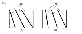
図3(A)は、カメラ20Lからの左のカメラ画像を示す。図3(B)は、カメラ20Rからの右のカメラ画像を示す。本実施形態では、左のカメラ画像を基準画像とし、右のカメラ画像を当該基準画像に対応する画像として取り扱う。各カメラ画像には、道路面31上にペイントされた道路標識である白線または黄色線の直線領域300,301が含まれている。
FIG. 3A shows a left camera image from the
特徴量抽出部12は、画像取得部11で取得した各カメラ画像(左右の画像)の特徴量を抽出する(ステップS2,S3)。具体的には、特徴量抽出部12は特徴量として、各カメラ画像から輝度勾配が大きい画素が直線状に連なっているものを直線領域として検出する。
The feature
ここで、輝度勾配とは、画素近傍での輝度変化の度合いを示すものであり、図2に示す監視領域200の場合に、道路面31上の白線の境界に相当する画像中の境界で大きな値を示すエッジ画像である。特徴量抽出部12は、例えばSobelオペレータのようなフィルタを画像に重畳する方法によりエッジ画像を求める(ステップS2)。
Here, the luminance gradient indicates the degree of luminance change in the vicinity of the pixel, and in the case of the
以下、具体的にエッジ画像を求める方法を説明する。 Hereinafter, a specific method for obtaining an edge image will be described.
画像中の位置(x,y)での輝度をI(x,y)とし、フィルタの各要素Fx(i,j)、Fy(i,j)が所定値に設定されて、このフィルタを画像に重畳して得られる値をGx、Gyとすると、下記の関係式(1)が得られる。

関係式(1)は、各位置(x,y)の近傍での水平方向および垂直方向の輝度変化の度合いを示すので、輝度勾配強度G(x,y)は、下記の数式(2)により算出できる。
よって、輝度勾配強度が予め設定された閾値より大きい画素のみを抽出するフィルタ処理により、エッジ画素を求めることができる。図4(A),(B)は、カメラ20L,20Rが図2に示すように設置される場合に、各カメラ画像から得られるエッジ画像400,401の一例を示す。なお、他に輝度勾配を求めるフィルタとしては、Laplacian、Robinson、Canny等のような様々なものがあり、いずれも適用可能である。
Therefore, an edge pixel can be obtained by a filter process that extracts only pixels whose luminance gradient intensity is greater than a preset threshold value. 4A and 4B show examples of
次に、特徴量抽出部12は、エッジ画像(エッジ画素)を求めた後に、例えばハフ変換方法を用いてエッジ画素を通る直線(直線領域)を検出する(ステップS3)。具体的には、エッジ画素の位置(x,y)を、下記関係式(3)を用いて、(ρ,θ)空間の三角関数曲線に変換する。
特徴量抽出部12は、複数のエッジ画素から生じる複数曲線の交点が直線に対応することから、直線を「ax+by+c=0」の式で表現した場合に、前記関係式(3)と交点の座標値(ρ,θ)とを使用して直線のパラメータ(a,b,c)を算出する。
Since the intersection of a plurality of curves generated from a plurality of edge pixels corresponds to a straight line, the feature
なお、例えばハフ変換方法以外に直線(直線領域)を検出する方法として、RANSAC(RANdom SAmple Consensus)のようなロバスト推定方法も適用可能である。この方法は、ランダムに選択された複数のエッジ画素を初期値として、最小2乗法等によりエッジ画素群に直線当てはめ処理を実行する。この場合、直線からの外れ値(距離)が大きい画素を取り除く処理と、外れ値が小さいエッジ画素を新たに含めて再度同様の方法で直線当てはめ処理を実行する。最大の外れ値が許容範囲に収まるまで、以上の直線当てはめ処理を繰り返すことにより、直線上に並ぶエッジ画素を通る直線(直線領域)を検出できる。 For example, a robust estimation method such as RANSAC (RANdom SAmple Consensus) is also applicable as a method for detecting a straight line (straight line region) other than the Hough transform method. In this method, a straight line fitting process is executed on an edge pixel group by a least square method or the like using a plurality of randomly selected edge pixels as initial values. In this case, the process of removing pixels having a large outlier (distance) from the straight line and the line fitting process are again performed in the same manner by newly including an edge pixel having a small outlier. By repeating the above-described straight line fitting process until the maximum outlier falls within the allowable range, a straight line (straight line region) passing through the edge pixels arranged on the straight line can be detected.
以上のようにして、図4(A),(B)に示すように、エッジ画素群400,401が不連続である場合や、くの字状に曲って連続する場合でも正しく直線(直線領域)を求めることができる。特徴量抽出部12は、直線検出処理を各カメラ画像に対して実行し、カメラ画像毎に2つ以上の直線(直線領域)を求める。
As described above, as shown in FIGS. 4A and 4B, even when the
なお、本実施形態では、各カメラ画像が平行等位化された画像である場合を想定している。平行等位化された画像とは、各カメラ20L,20Rの光軸が平行で、レンズ歪みがないように調整された画像である。
In the present embodiment, it is assumed that each camera image is an image obtained by parallel equalization. A parallel-equalized image is an image adjusted so that the optical axes of the
次に、対応検出部13は、特徴量抽出部12で求められた各カメラ画像の特徴量(直線領域)を比較し、各カメラ画像間での対応関係を求める対応検出処理を実行する(ステップS4)。ここで、対応関係とは、各カメラ20L,20Rの共通撮影領域に存在する同一の実像に基づいて、各カメラ画像に含まれる直線(直線領域)の組を意味する。具体的には、直線であるエピポーラ線上に位置する対応点の組(少なくとも4組)を意味する。
Next, the
前述したように本実施形態では、各カメラ画像が平行等位化された画像である場合を想定している。平行等位化された画像の場合は、エピポーラ拘束条件により、基準画像(左のカメラ画像)上の任意の点は、一方の画像(右のカメラ画像)上の同じy座標上に位置する特性がある。このため、対応検出部13は、1次元探索方法により対応点の探索処理を実行する。以下、対応検出部13による対応関係の検出方法を説明する。
As described above, in the present embodiment, it is assumed that each camera image is an image obtained by parallel equalization. In the case of an image parallelized, any point on the reference image (left camera image) is located on the same y coordinate on one image (right camera image) due to the epipolar constraint condition. There is. For this reason, the
具体的には、対応検出部13は、例えば注目画素近傍の画像特徴を用いた領域マッチングによる方法を適用して、各カメラ画像間での対応関係を検出する。画像特徴とは、検出した直線近傍領域と他の領域とを区別することができる画像から抽出できる輝度、色、動き等の物理量を意味する。
Specifically, the
領域マッチング方法とは、比較元の画像領域と比較先の画像領域との一致度(ER)を算出する方法である。例えばSAD(Sum of Absolute Difference)方法を適用する算出方法を説明する。 The region matching method is a method of calculating the degree of coincidence (E R ) between the comparison source image region and the comparison destination image region. For example, a calculation method using the SAD (Sum of Absolute Difference) method will be described.
ここで、比較する2つの画像領域が同形としてRで表し、画像領域(R)中の位置を(x,y)とし場合に、下記関係式(4)から一致度(ER)を算出できる。
前記関係式(4)から、一致度(ER)の値が小さいほど、2つの画像領域は一致している度合いが高いことを意味する。また、エッジが類似している複数の直線がある場合には、平行等位化されている画像においては、同一y座標上では、直線間の距離はいずれの画像においても等しくなる。このため、画像領域(R)の一致度を示す情報を用いることで、対応関係の信頼度を向上させることが可能である。 From the relational expression (4), the smaller the matching degree (E R ), the higher the degree of matching between the two image regions. In addition, when there are a plurality of straight lines having similar edges, the distance between the straight lines is the same in any image on the same y coordinate in an image that is parallel-equalized. For this reason, it is possible to improve the reliability of the correspondence relationship by using information indicating the degree of coincidence of the image regions (R).
次に、画像変換行列算出部14は、対応検出部13で検出された対応関係から、カメラ画像間の画像変換パラメータである射影変換行列Hを算出する(ステップS5)。具体的には、画像変換行列算出部14は、平行等位化されている画像において、対応検出部13で算出した対応関係として少なくとも4組の対応点から、カメラ画像間の画像変換パラメータである射影変換行列Hを算出する。この射影変換行列Hと画像座標系上の対応点とは、下記の関係式(5)に示すような関係がある。
なお、mTは転置行列を意味し、m−1は逆行列を意味する。 Note that m T means a transposed matrix, and m −1 means an inverse matrix.
この場合、射影変換行列Hは、下記の関係式(6)に示すように3×3の行列として記述できる。
ここで、射影変換行列Hは未知パラメータh0〜h7の8個であり、一組の対応点は2個の式を与える。したがって、4組以上の対応点があれば、最小2乗法によりこの射影変換行列Hを求めることができる。画像変換行列出力部15は、画像変換行列算出部14で算出された射影変換行列Hを、ステレオキャリブレーション結果として出力する。
Here, the projective transformation matrix H is eight unknown parameters h0 to h7, and one set of corresponding points gives two equations. Therefore, if there are four or more pairs of corresponding points, this projective transformation matrix H can be obtained by the method of least squares. The image conversion
以上のように本実施形態によれば、ステレオカメラの左右カメラから取得される各カメラ画像から特徴量(直線領域)を検出し、これらの特徴量から比較対象の画像領域(R)の一致度(位置)に基づいて例えば4つの対応点(対応関係)を検出する。この4つの対応点から、カメラ画像間の画像変換パラメータ情報(射影変換行列H)を算出する。この画像変換パラメータ情報(射影変換行列H)は、ステレオカメラの各カメラ画像間のキャリブレーションを実行するための情報として使用できる。 As described above, according to the present embodiment, the feature amount (straight region) is detected from each camera image acquired from the left and right cameras of the stereo camera, and the degree of coincidence of the comparison target image region (R) from these feature amounts. For example, four corresponding points (corresponding relationships) are detected based on (position). Image conversion parameter information (projective transformation matrix H) between the camera images is calculated from these four corresponding points. This image conversion parameter information (projection conversion matrix H) can be used as information for executing calibration between the camera images of the stereo camera.
本実施形態では、各カメラ画像から少なくとも2つの直線領域から例えば4つの対応点を検出することで、カメラ画像間の画像変換パラメータ情報(行列H)を算出することができる。従って、各カメラの共通撮影領域として、例えば一車線の道路面上から白線などの道路標示パターンを各カメラ画像として取得し、少なくとも2本の直線領域を検出すれば、画像変換パラメータ情報(射影変換行列H)を算出することができる。 In this embodiment, image conversion parameter information (matrix H) between camera images can be calculated by detecting, for example, four corresponding points from at least two linear regions from each camera image. Therefore, as a common shooting area of each camera, for example, a road marking pattern such as a white line is acquired as each camera image from the road surface of one lane, and if at least two straight line areas are detected, image conversion parameter information (projection conversion) is obtained. Matrix H) can be calculated.
ここで、従来のように例えば道路上にマークなどを予め設けて、少なくとも4組以上の対応直線組を検出するステレオキャリブレーション方法では、一車線の道路面を監視領域(各カメラの共通撮影領域)とする場合には、必要となる直線数が不足する場合が多いため、適用範囲が狭い。これに対して、本実施形態の方法であれば、例えば一車線の道路面上から白線などの道路標示パターンのカメラ画像を取得できれば、各カメラ画像間のキャリブレーションを実行できるため、適用範囲が広いステレオキャリブレーションの自動化を実現することができる。 Here, in the conventional stereo calibration method in which, for example, a mark or the like is provided in advance on a road and at least four pairs of corresponding straight lines are detected, a road surface of one lane is monitored as a monitoring area (a common shooting area for each camera). ), The required number of straight lines is often insufficient, so the applicable range is narrow. On the other hand, with the method of the present embodiment, for example, if a camera image of a road marking pattern such as a white line can be acquired from the road surface of one lane, calibration between each camera image can be executed, so the applicable range is A wide range of stereo calibration can be automated.
なお、本実施形態において、特徴量抽出部12で特徴量として直線(直線領域)を抽出する方法を適用する場合について述べたが、これに限ることなく以下のような特徴量から対応関係を検出する方法でもよい。例えば、道路面上の平面上パターンとして道路面にペイントされた数字・文字等の道路標示パターンでもよい。また、道路の繋ぎ目やマンホール等の道路付帯設備に対応する平面上パターンでもよい。さらに、道路面上の平面上パターン以外に、列車軌道線に対応する平面上パターンでもよい。また、平面上パターンとして、路面上に投影された太陽光、照明光と影部の境界、もしくは夜間に投影されるスポット光の境界部でもよい。
In the present embodiment, the case of applying a method of extracting a straight line (straight line region) as a feature amount in the feature
[第2の実施形態]
図5、図7、図8は、第2の実施形態に関する画像処理装置を説明するための図である。
[Second Embodiment]
5, FIG. 7, and FIG. 8 are diagrams for explaining an image processing apparatus according to the second embodiment.
図7に示すように、本実施形態の画像処理装置10は、第1の実施形態と同様に、例えばステレオ画像認識を利用する道路監視システム1に適用されるもので、画像取得部11と、特徴量抽出部12と、対応検出部13と、画像変換行列算出部14と、画像変換行列出力部15とを有する。さらに、本実施形態の画像処理装置10は、検出対象領域算出部16と、検出対象領域出力部17を有する。
As shown in FIG. 7, the
以下、本実施形態の画像処理装置10の動作を説明する。なお、画像取得部11、特徴量抽出部12、対応検出部13、画像変換行列算出部14、及び画像変換行列出力部15のそれぞれの動作は、第1の実施形態と同様であるため、説明を省略する。
Hereinafter, the operation of the
検出対象領域算出部16は、対応検出部13で対応付けられた特徴量(例えば直線領域)に関して、特に道路面上の車線や列車軌道上のレールを検出対象領域を算出する。具体的には、検出対象領域算出部16は、図5(A),(B)に示すように、道路面上の車線500,501を表す特徴量について、車線内に含まれる領域を検出対象領域として算出する。検出対象領域は、図8に示すように、斜線で示した領域800である。ここで、図8は、図5(A),(B)に示す車線500,501内に含まれる領域の一部を拡大した図である。検出対象領域出力部17は、検出対象領域算出部16で算出した領域情報(800)を算出結果として出力する。
The detection target
本実施形態によれば、検出対象領域算出部16により、例えば道路が2車線の場合に、最も外側の2本の線で囲まれた領域を、ステレオ画像認識対象の検出領域(図2に示す200)として決定することができる。
According to this embodiment, when the road to be detected is, for example, two lanes, the detection target
[第3の実施形態]
図9は、第3の実施形態に関する画像処理装置を説明するための図である。
[Third Embodiment]
FIG. 9 is a diagram for explaining an image processing apparatus according to the third embodiment.
図9に示すように、本実施形態の画像処理装置10は、第1の実施形態と同様に、例えばステレオ画像認識を利用する道路監視システム1に適用されるもので、画像取得部11と、特徴量抽出部12と、対応検出部13と、画像変換行列算出部14と、画像変換行列出力部15とを有する。さらに、本実施形態の画像処理装置10は、検出対象領域算出部18と、検出対象領域出力部19を有する。
As shown in FIG. 9, the
以下、本実施形態の画像処理装置10の動作を説明する。なお、画像取得部11、特徴量抽出部12、対応検出部13、画像変換行列算出部14、及び画像変換行列出力部15のそれぞれの動作は、第1の実施形態と同様であるため、説明を省略する。
Hereinafter, the operation of the
検出対象領域算出部18は、画像変換行列算出部14で算出された射影変換行列(カメラ画像間の画像変換パラメータ情報)を利用して、基準カメラ画像から一方のカメラ画像を変換し、2つのカメラ画像間で比較する。検出対象領域算出部18は、カメラ画像間の差異に基づいて同一平面上に存在する領域を検出対象領域として算出する。即ち、平面上に存在する領域についてはカメラ画像間で差異がない場合には、同一平面と推定できることから、同一平面上に存在する領域を検出対象領域として算出することができる。検出対象領域出力部19は、検出対象領域算出部16で算出した領域情報を算出結果として出力する。
The detection target
本実施形態によれば、検出対象領域算出部18により、カメラ画像間の画像変換パラメータ情報)を利用して、2つのカメラ画像間での比較結果(差異)により監視対象の検出対象領域を算出できる。従って、監視対象の検出領域を推定する場合の信頼性を向上させることが可能となる。
According to this embodiment, the detection target
さらに、算出した検出対象領域に基づいて、ステレオ監視画像処理を実行することにより、検出対象物の位置を求めることができる。この算出された位置情報に基づいて、検出対象領域を補正することも可能である。換言すれば、本実施形態によれば、各カメラ画像の中で、カメラ画像間で差異がない一致する領域を検出対象領域として決定し、逆に差異がある不一致の領域を検出対象領域から除く処理が可能となる。 Furthermore, the position of the detection target can be obtained by executing stereo monitoring image processing based on the calculated detection target region. It is also possible to correct the detection target area based on the calculated position information. In other words, according to the present embodiment, in each camera image, a matching region having no difference between the camera images is determined as a detection target region, and conversely, a non-matching region having a difference is excluded from the detection target region. Processing is possible.
[応用例]
以上のような第1から第3の実施形態で説明した画像処理装置10を適用することにより、ステレオ画像認識におけるステレオキャリブレーションを実現することができる。従って、ステレオ画像認識を利用して、道路面上を走行する車両を監視する道路監視システム1を構築することができる。
[Application example]
By applying the
さらに、第1から第3の実施形態で説明した画像処理装置10を適用することにより、ステレオ画像認識を利用した監視システムとして、例えば駅の線路とホームを含む共通領域を監視領域とする監視システムを構築することが可能である。このような監視システムでは、線路とホームには段差があるため、画像処理装置10を適用したステレオ画像認識装置により、ホームのエッジで線路とホームの各領域を区別することができる。このようなステレオ画像認識を利用して、監視システムは、各カメラ画像から、例えば線路に落ちた人物を認識し、また、ホームの端にいる人物を認識することができる。
Further, by applying the
本発明のいくつかの実施形態を説明したが、これらの実施形態は、例として提示したものであり、発明の範囲を限定することは意図していない。これら新規な実施形態は、その他の様々な形態で実施されることが可能であり、発明の要旨を逸脱しない範囲で、種々の省略、置き換え、変更を行うことができる。これら実施形態やその変形は、発明の範囲や要旨に含まれるとともに、特許請求の範囲に記載された発明とその均等の範囲に含まれる。 Although several embodiments of the present invention have been described, these embodiments are presented by way of example and are not intended to limit the scope of the invention. These novel embodiments can be implemented in various other forms, and various omissions, replacements, and changes can be made without departing from the scope of the invention. These embodiments and modifications thereof are included in the scope and gist of the invention, and are included in the invention described in the claims and the equivalents thereof.
1…道路監視システム、10…画像処理装置、11…画像取得部、
12…特徴量抽出部、13…対応検出部、14…画像変換行列算出部、
15…画像変換行列出力部、16,18…検出対象領域算出部、
17,19…検出対象領域出力部、20…ステレオカメラ、
20L…左のカメラ、20R…右のカメラ。
DESCRIPTION OF
12 ... feature amount extraction unit, 13 ... correspondence detection unit, 14 ... image conversion matrix calculation unit,
15 ... image conversion matrix output unit, 16, 18 ... detection target region calculation unit,
17, 19 ... detection target region output unit, 20 ... stereo camera,
20L ... Left camera, 20R ... Right camera.
Claims (9)
前記カメラ毎の画像データから前記共通撮影領域の特徴量情報として、前記共通撮影領域に存在する同一の実像に基づいた少なくとも2つの平面上パターンを算出する特徴量抽出手段と、
前記2つの平面上パターンにおいて前記カメラ毎の画像データ間の対応関係を検出する対応検出手段と、
前記対応検出手段により算出された対応関係情報に基づいて、前記カメラ毎の画像間の画像変換パラメータ情報を算出する算出手段と
を具備したことを特徴とする画像処理装置。 Image acquisition means for acquiring image data corresponding to a common shooting area from a plurality of cameras;
Feature amount extraction means for calculating at least two on-plane patterns based on the same real image existing in the common photographing region as feature amount information of the common photographing region from the image data for each camera;
Correspondence detection means for detecting a correspondence relationship between the image data for each camera in the two on-plane patterns;
An image processing apparatus comprising: a calculation unit that calculates image conversion parameter information between images for each camera based on the correspondence relationship information calculated by the correspondence detection unit.
前記平面上パターンとして前記同一の実像に基づいた少なくとも2つの直線領域を検出するように構成されていることを特徴とする請求項1に記載の画像処理装置。 The feature amount extraction means includes:
The image processing apparatus according to claim 1, wherein at least two linear regions based on the same real image are detected as the planar pattern.
前記対応関係として前記少なくとも2つの直線領域の複数の対応点の組を検出するように構成されていることを特徴とする請求項2に記載の画像処理装置。 The correspondence detecting means includes
The image processing apparatus according to claim 2, wherein the image processing apparatus is configured to detect a set of a plurality of corresponding points of the at least two linear regions as the correspondence relationship.
前記特徴量情報として、前記共通撮影領域に含まれる道路標識用パターン、道路に付帯する平面状の構造物、列車路線軌道、あるいは平面上に投影された影または光のいずれかに対応する少なくとも2つの平面上パターンを算出するように構成されていることを特徴とする請求項1に記載の画像処理装置。 The feature amount extraction means includes:
As the feature amount information, at least 2 corresponding to any one of a road sign pattern included in the common imaging region, a planar structure attached to the road, a train route track, or a shadow or light projected on a plane. The image processing apparatus according to claim 1, wherein the image processing apparatus is configured to calculate two on-plane patterns.
前記ステレオカメラに含まれる複数のカメラから共通撮影領域に対応する画像データを取得する処理と、
前記カメラ毎の画像データから前記共通撮影領域の特徴量情報として、前記共通撮影領域に存在する同一の実像に基づいた少なくとも2つの平面上パターンを算出する処理と、
前記2つの平面上パターンにおいて前記カメラ毎の画像データ間の対応関係を検出する処理と、
前記対応検出手段により算出された対応関係情報に基づいて、前記カメラ毎の画像間の画像変換パラメータ情報を算出する処理と
を有することを特徴とする方法。 A method of performing a stereo calibration applied to stereo image recognition using a stereo camera,
Processing for acquiring image data corresponding to a common shooting area from a plurality of cameras included in the stereo camera;
Processing for calculating at least two on-plane patterns based on the same real image existing in the common imaging area as feature amount information of the common imaging area from image data for each camera;
A process of detecting a correspondence between the image data for each camera in the two on-plane patterns;
And a process of calculating image conversion parameter information between images for each camera based on the correspondence information calculated by the correspondence detection means.
Priority Applications (1)
| Application Number | Priority Date | Filing Date | Title |
|---|---|---|---|
| JP2011119288A JP2012248004A (en) | 2011-05-27 | 2011-05-27 | Image processing system, image recognition device and method |
Applications Claiming Priority (1)
| Application Number | Priority Date | Filing Date | Title |
|---|---|---|---|
| JP2011119288A JP2012248004A (en) | 2011-05-27 | 2011-05-27 | Image processing system, image recognition device and method |
Publications (1)
| Publication Number | Publication Date |
|---|---|
| JP2012248004A true JP2012248004A (en) | 2012-12-13 |
Family
ID=47468389
Family Applications (1)
| Application Number | Title | Priority Date | Filing Date |
|---|---|---|---|
| JP2011119288A Pending JP2012248004A (en) | 2011-05-27 | 2011-05-27 | Image processing system, image recognition device and method |
Country Status (1)
| Country | Link |
|---|---|
| JP (1) | JP2012248004A (en) |
Cited By (4)
| Publication number | Priority date | Publication date | Assignee | Title |
|---|---|---|---|---|
| JP2016192107A (en) * | 2015-03-31 | 2016-11-10 | 公益財団法人鉄道総合技術研究所 | Stereo image processing method and apparatus |
| JP2020038101A (en) * | 2018-09-03 | 2020-03-12 | 株式会社東芝 | Image processing device, driving support system, image processing method, and program |
| CN112731436A (en) * | 2020-12-17 | 2021-04-30 | 浙江大学 | Multi-mode data fusion travelable area detection method based on point cloud up-sampling |
| WO2023249126A1 (en) * | 2022-06-24 | 2023-12-28 | 日立Astemo株式会社 | Image processing device and image processing method |
Citations (3)
| Publication number | Priority date | Publication date | Assignee | Title |
|---|---|---|---|---|
| JPH11328365A (en) * | 1998-05-14 | 1999-11-30 | Toshiba Corp | Image monitoring apparatus and method |
| JP2000293693A (en) * | 1999-03-31 | 2000-10-20 | Toshiba Corp | Obstacle detection method and device |
| JP2004334819A (en) * | 2003-03-13 | 2004-11-25 | Toshiba Corp | Stereo calibration device and stereo image monitoring device using the same |
-
2011
- 2011-05-27 JP JP2011119288A patent/JP2012248004A/en active Pending
Patent Citations (3)
| Publication number | Priority date | Publication date | Assignee | Title |
|---|---|---|---|---|
| JPH11328365A (en) * | 1998-05-14 | 1999-11-30 | Toshiba Corp | Image monitoring apparatus and method |
| JP2000293693A (en) * | 1999-03-31 | 2000-10-20 | Toshiba Corp | Obstacle detection method and device |
| JP2004334819A (en) * | 2003-03-13 | 2004-11-25 | Toshiba Corp | Stereo calibration device and stereo image monitoring device using the same |
Non-Patent Citations (2)
| Title |
|---|
| CSNG200201374004; 奥富 正敏、外2名: '"ステレオ画像からの射影変換行列の抽出による道路領域検出"' 日本ロボット学会誌 Vol.18, No.8, 20001115, p.1105-1111, (社)日本ロボット学会 * |
| JPN6015000293; 奥富 正敏、外2名: '"ステレオ画像からの射影変換行列の抽出による道路領域検出"' 日本ロボット学会誌 Vol.18, No.8, 20001115, p.1105-1111, (社)日本ロボット学会 * |
Cited By (6)
| Publication number | Priority date | Publication date | Assignee | Title |
|---|---|---|---|---|
| JP2016192107A (en) * | 2015-03-31 | 2016-11-10 | 公益財団法人鉄道総合技術研究所 | Stereo image processing method and apparatus |
| JP2020038101A (en) * | 2018-09-03 | 2020-03-12 | 株式会社東芝 | Image processing device, driving support system, image processing method, and program |
| CN112731436A (en) * | 2020-12-17 | 2021-04-30 | 浙江大学 | Multi-mode data fusion travelable area detection method based on point cloud up-sampling |
| CN112731436B (en) * | 2020-12-17 | 2024-03-19 | 浙江大学 | Multimodal data fusion drivable area detection method based on point cloud upsampling |
| WO2023249126A1 (en) * | 2022-06-24 | 2023-12-28 | 日立Astemo株式会社 | Image processing device and image processing method |
| JP2024002479A (en) * | 2022-06-24 | 2024-01-11 | 日立Astemo株式会社 | Image processing device and image processing method |
Similar Documents
| Publication | Publication Date | Title |
|---|---|---|
| CN117078717B (en) | Road vehicle trajectory extraction method based on UAV monocular camera | |
| JP4363295B2 (en) | Plane estimation method using stereo images | |
| JP6260891B2 (en) | Image processing apparatus and image processing method | |
| JP6408434B2 (en) | Road marking body deterioration detection method | |
| JP2004334819A (en) | Stereo calibration device and stereo image monitoring device using the same | |
| CN104949657A (en) | Object detection device, object detection method, and computer readable storage medium comprising objection detection program | |
| CN111862146B (en) | Target object positioning method and device | |
| CN103988241A (en) | Detection device, method, and program | |
| KR20180098945A (en) | Method and apparatus for measuring speed of vehicle by using fixed single camera | |
| KR20140087485A (en) | Method of estimating the location of mobile robot using ray-tracing technique | |
| CN107067752A (en) | Automobile speedestimate system and method based on unmanned plane image | |
| CN112868049A (en) | Efficient self-motion estimation using patch-based projection correlation | |
| US20160035107A1 (en) | Moving object detection | |
| JPWO2011039977A1 (en) | Crosswalk sign detection method and crosswalk sign detection device | |
| US20200193184A1 (en) | Image processing device and image processing method | |
| JP6956051B2 (en) | Image processing equipment, driving support system, image processing method and program | |
| US10205911B2 (en) | Method and system for detecting running | |
| JP2012159470A (en) | Vehicle image recognition device | |
| JP5981284B2 (en) | Object detection device and object detection method | |
| Ke et al. | Roadway surveillance video camera calibration using standard shipping container | |
| JP6492603B2 (en) | Image processing apparatus, system, image processing method, and program | |
| WO2014054124A1 (en) | Road surface markings detection device and road surface markings detection method | |
| KR101371875B1 (en) | A vehicle detection and distance measurement system and method between the vehicles using stereo vision | |
| KR102049666B1 (en) | Method for Estimating 6-DOF Relative Displacement Using Vision-based Localization and Apparatus Therefor | |
| JP4762026B2 (en) | Road sign database construction device |
Legal Events
| Date | Code | Title | Description |
|---|---|---|---|
| RD04 | Notification of resignation of power of attorney |
Free format text: JAPANESE INTERMEDIATE CODE: A7424 Effective date: 20131205 |
|
| RD04 | Notification of resignation of power of attorney |
Free format text: JAPANESE INTERMEDIATE CODE: A7424 Effective date: 20131212 |
|
| RD04 | Notification of resignation of power of attorney |
Free format text: JAPANESE INTERMEDIATE CODE: A7424 Effective date: 20131219 |
|
| RD04 | Notification of resignation of power of attorney |
Free format text: JAPANESE INTERMEDIATE CODE: A7424 Effective date: 20131226 |
|
| RD04 | Notification of resignation of power of attorney |
Free format text: JAPANESE INTERMEDIATE CODE: A7424 Effective date: 20140109 |
|
| A621 | Written request for application examination |
Free format text: JAPANESE INTERMEDIATE CODE: A621 Effective date: 20140310 |
|
| A977 | Report on retrieval |
Free format text: JAPANESE INTERMEDIATE CODE: A971007 Effective date: 20141226 |
|
| A131 | Notification of reasons for refusal |
Free format text: JAPANESE INTERMEDIATE CODE: A131 Effective date: 20150113 |
|
| A02 | Decision of refusal |
Free format text: JAPANESE INTERMEDIATE CODE: A02 Effective date: 20151013 |