JP2012248497A - Battery and battery electrode - Google Patents
Battery and battery electrode Download PDFInfo
- Publication number
- JP2012248497A JP2012248497A JP2011121245A JP2011121245A JP2012248497A JP 2012248497 A JP2012248497 A JP 2012248497A JP 2011121245 A JP2011121245 A JP 2011121245A JP 2011121245 A JP2011121245 A JP 2011121245A JP 2012248497 A JP2012248497 A JP 2012248497A
- Authority
- JP
- Japan
- Prior art keywords
- frame
- electrode
- battery
- resin member
- substrate
- Prior art date
- Legal status (The legal status is an assumption and is not a legal conclusion. Google has not performed a legal analysis and makes no representation as to the accuracy of the status listed.)
- Withdrawn
Links
Images




Classifications
-
- Y—GENERAL TAGGING OF NEW TECHNOLOGICAL DEVELOPMENTS; GENERAL TAGGING OF CROSS-SECTIONAL TECHNOLOGIES SPANNING OVER SEVERAL SECTIONS OF THE IPC; TECHNICAL SUBJECTS COVERED BY FORMER USPC CROSS-REFERENCE ART COLLECTIONS [XRACs] AND DIGESTS
- Y02—TECHNOLOGIES OR APPLICATIONS FOR MITIGATION OR ADAPTATION AGAINST CLIMATE CHANGE
- Y02E—REDUCTION OF GREENHOUSE GAS [GHG] EMISSIONS, RELATED TO ENERGY GENERATION, TRANSMISSION OR DISTRIBUTION
- Y02E60/00—Enabling technologies; Technologies with a potential or indirect contribution to GHG emissions mitigation
- Y02E60/10—Energy storage using batteries
Landscapes
- Sealing Battery Cases Or Jackets (AREA)
Abstract
【課題】電池を大型化させることなく容量を大きくした電池及び電極を提供する。
【解決手段】第1基板10、第1基板10の上面に設けられた第1枠体11および第1枠体11を囲むように設けられた第2枠体12を有する第1電極1と、同様構成で第1枠体11の上面と第3枠体21の下面とが、および第2枠体12の上面と第4枠体22の下面とがそれぞれ対向するように第1電極1の上方に位置している第2電極2と、環状の第1樹脂部材3と、第1樹脂部材3の外周よりも外側の領域で第1電極1と第2電極2との間に充填された環状の第2樹脂部材4と、第1電極1、第2電極2および第1樹脂部材3によって囲まれた空間に設けられて第1電極1および第2電極2に電気的に繋がっている発電要素7とを有し、第2枠体12の上面と第4枠体22の下面との間隔が、第1枠体11の上面と第3枠体21の下面との間隔よりも大きい電池である。
【選択図】図2A battery and an electrode having an increased capacity without increasing the size of the battery are provided.
A first electrode having a first substrate, a first frame provided on an upper surface of the first substrate, and a second frame provided so as to surround the first frame. Above the first electrode 1 with the same configuration, the upper surface of the first frame 11 and the lower surface of the third frame 21 and the upper surface of the second frame 12 and the lower surface of the fourth frame 22 face each other. The second electrode 2 located in the ring, the annular first resin member 3, and the annular filled between the first electrode 1 and the second electrode 2 in a region outside the outer periphery of the first resin member 3 Power generation element provided in a space surrounded by the second resin member 4 and the first electrode 1, the second electrode 2, and the first resin member 3 and electrically connected to the first electrode 1 and the second electrode 2. 7 and the distance between the upper surface of the second frame 12 and the lower surface of the fourth frame 22 is such that the upper surface of the first frame 11 and the lower surface of the third frame 21 It is a great battery than the interval.
[Selection] Figure 2
Description
本発明は、電池およびこれに用いられる電池用電極に関するものである。本発明の電池は、例えば携帯電話、携帯情報端末およびノート型パソコンのような電子機器の電源として用いることができる。 The present invention relates to a battery and a battery electrode used therefor. The battery of the present invention can be used as a power source for electronic devices such as mobile phones, portable information terminals, and notebook computers.
電池として、金属製の一対の電極および樹脂製の封止材から成る電池用パッケージの内部に発電要素が設けられたものが知られている。このような電池としては、例えば、特許文献1に記載の扁平形電池が挙げられる。
As a battery, a battery in which a power generation element is provided inside a battery package made of a pair of metal electrodes and a resin sealing material is known. Examples of such a battery include a flat battery described in
特許文献1に記載の扁平形電池は、正極缶にガスケットを介して負極缶を嵌めこむことで電池容器を形成している。さらに、電池容器に発電要素が収容されることで電池として用いられる。
In the flat battery described in
一般に携帯型の電子機器の電源に用いられる電池は、電子機器の小型化に伴い容量を確保しながら小型化することが求められている。また、電子機器の落下等による衝撃によって、電池に圧力が加わることがある。 In general, a battery used for a power source of a portable electronic device is required to be downsized while securing a capacity as the electronic device is downsized. In addition, pressure may be applied to the battery due to an impact caused by dropping the electronic device.
特許文献1に記載の扁平形電池は、一対の電極をガスケットで保持している。このため、扁平形電池に上下方向から圧力が加わった際に、ガスケットが電極の平面方向に変形して、発電要素に圧力が加わる可能性があった。幅広なガスケットを用いることによって、上記の圧力を抑制することができるが、その場合、扁平形電池の大きさを維持することが困難であった。また、扁平形電池の大きさを維持したまま、幅広なガスケットを用いると、発電要素が封入される空間を広く形成することが困難であった。これらのことから、扁平形電池を大型化させることなく、容量を大きくすることが困難であった。
The flat battery described in
本発明の一態様に係る電池は、第1基板、第1基板の上面に設けられた第1枠体および第1枠体を囲むように設けられた第2枠体を有する第1電極と、第2基板、第2基板の下面に設けられた第3枠体および第3枠体を囲むように設けられた第4枠体を有し、第1枠体の上面と第3枠体の下面とが、および第2枠体の上面と第4枠体の下面とがそれぞれ対向するように第1電極の上方に位置している第2電極と、第1枠体の上面と第3枠体の下面との間に位置して第1枠体および第3枠体を接合している環状の第1樹脂部材と、第1樹脂部材の外周よりも外側の領域で第1電極と第2電極との間に充填された環状の第2樹脂部材と、第1電極、第2電極および第1樹脂部材によって囲まれた空間に設けられて第1電極および第2電極に電気的に繋がっている発電要素とを有し、第2枠体の上面と第4枠体の下面との間隔が、第1枠体の上面と第3枠体の下面との間隔よりも大きい。 A battery according to an aspect of the present invention includes a first electrode having a first substrate, a first frame provided on an upper surface of the first substrate, and a second frame provided so as to surround the first frame, A second substrate, a third frame provided on a lower surface of the second substrate, and a fourth frame provided so as to surround the third frame, and an upper surface of the first frame and a lower surface of the third frame And the second electrode positioned above the first electrode such that the upper surface of the second frame body and the lower surface of the fourth frame body face each other, and the upper surface of the first frame body and the third frame body An annular first resin member that is positioned between the lower surface of the first frame member and the third frame member, and a first electrode and a second electrode in a region outside the outer periphery of the first resin member And an annular second resin member filled between the first electrode, the second electrode, and the first resin member, and electrically connected to the first electrode and the second electrode. And a power generating element is connected, the distance between the upper surface and the lower surface of the fourth frame of the second frame is greater than the distance between the upper surface and the lower surface of the third frame of the first frame.
本発明の一態様に係る電池用電極は、第1基板、第1基板の上面に設けられた第1枠体および第1枠体を囲むように設けられた第2枠体を有する第1電極と、第2基板、第2基板の下面に設けられた第3枠体および第3枠体を囲むように設けられた第4枠体を有し、
第1枠体の上面と第3枠体の下面とが、および第2枠体の上面と第4枠体の下面とがそれぞれ対向するように第1電極の上方に位置して用いられる第2電極とからなり、第1枠体の上面と第3枠体の下面とを、および第2枠体の上面と第4枠体の下面とをそれぞれ対向させたときに、第2枠体の上面と第4枠体の下面との間隔が、第1枠体の上面と第3枠体の下面との間隔よりも大きい。
A battery electrode according to one aspect of the present invention includes a first substrate, a first frame provided on an upper surface of the first substrate, and a second frame provided so as to surround the first frame. And a second frame, a third frame provided on the lower surface of the second substrate, and a fourth frame provided so as to surround the third frame,
The second frame is used above the first electrode so that the upper surface of the first frame and the lower surface of the third frame are opposed to each other, and the upper surface of the second frame and the lower surface of the fourth frame are opposed to each other. An upper surface of the second frame when the upper surface of the first frame and the lower surface of the third frame are opposed to each other, and the upper surface of the second frame and the lower surface of the fourth frame are opposed to each other. And the lower surface of the fourth frame are larger than the distance between the upper surface of the first frame and the lower surface of the third frame.
上記態様の電池によれば、第2枠体の上面と第4枠体の下面との間隔が、第1枠体の上面と第3枠体の下面との間隔よりも大きいことによって、電池に上下方向から圧力が加わった際に、第1樹脂部材および第2樹脂部材を電池の外周側に変形させやすくすることができる。これにより、第1樹脂部材および第2樹脂部材が電池の中心側に変形することを抑制することができる。したがって、第1樹脂部材および第2樹脂部材の幅を過度に大きくしなくても、内部に大きな圧力が加わることを抑制できる。その結果、電池の容量を大きくすることができる。 According to the battery of the above aspect, the distance between the upper surface of the second frame body and the lower surface of the fourth frame body is larger than the distance between the upper surface of the first frame body and the lower surface of the third frame body. When pressure is applied from the vertical direction, the first resin member and the second resin member can be easily deformed to the outer peripheral side of the battery. Thereby, it can suppress that a 1st resin member and a 2nd resin member deform | transform into the center side of a battery. Therefore, it is possible to suppress a large pressure from being applied to the inside without excessively increasing the widths of the first resin member and the second resin member. As a result, the capacity of the battery can be increased.
本発明の電池用電極によれば、第1電極と第2電極とを対向させたときに第2枠体の上面と第4枠体の下面との間隔が、第1枠体の上面と第3枠体の下面との間隔よりも大きい。これにより、第1枠体の上面と第3枠体の下面との間の領域およびこの領域よりも外側の領域に樹脂部材を設けて第1電極と第2電極とを接合して電池を作製したときに、容量の大きな電池とすることができる。 According to the battery electrode of the present invention, when the first electrode and the second electrode face each other, the distance between the upper surface of the second frame and the lower surface of the fourth frame is such that the upper surface of the first frame and the It is larger than the distance from the lower surface of the three frame body. Thus, a resin member is provided in a region between the upper surface of the first frame and the lower surface of the third frame and a region outside this region, and the first electrode and the second electrode are joined to produce a battery. Battery with a large capacity.
以下、本発明の一実施形態に係る電池99および電池用電極98について図面を参照して説明する。
Hereinafter, a
<電池の構成>
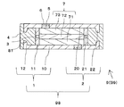
図1,2に示すように、本発明の一実施形態の電池99は、電池用パッケージ9と、電池用パッケージ9に封入された、電解質部材(図示せず)を含む発電要素7とを備えている。
<Battery configuration>
As shown in FIGS. 1 and 2, a
<電池用パッケージの構成>
電池用パッケージ9は、第1電極1と、第1電極1の上面側に第1電極1と離間して設けられた第2電極2と、平面視した場合に環状となるように、第1電極1と第2電極2とを接合した第1樹脂部材3と、第1電極1と第2電極2との間の領域であって、第1樹脂部材3よりも外周側の領域に充填された環状の第2樹脂部材4とによって構成される。
<Configuration of battery package>
The
第1電極1は、電池99における正極または負極として用いられる部材であって、第1基板10、第1基板10の上面に設けられた第1枠体11および第1枠体11を囲むように設けられた第2枠体12とによって構成されている。第1電極1は、外部の電子回路と電気的に接続されることによって電池99の内部で発生した電気を電子回路に伝えることができる。
The
第1基板10は、平板形状の部材であって、平面視したときの形状が円形状である。第1基板10は、上面と下面とに開口する貫通孔5を有している。貫通孔5は、電解質部材を電池用パッケージ9の内部の発電要素7を配置した領域に封入する際の封入孔として用いられる。なお、電解質部材の封入を行なった後に、貫通孔5は、封止材6によって封止される。封止材6としては、例えばエポキシ樹脂、フェノール樹脂またはフラン樹脂等の樹脂材料を用いることができる。また、封止材6としては、金属片を用いることもできる。
The 1st board |
第1基板10としては、例えば、ニッケル、ステンレスまたはアルミニウムのような導電性を有する金属材料を用いることができる。第1電極1を正極として用いる場合は、電解質部材に面する上面部分が、金、白金、タングステンまたはアルミニウムのような耐食性に優れる金属材料を用いることが望ましい。
As the
第1枠体11は、第2枠体12と共に第2樹脂部材4が充填される空間を形成する機能を有している。第1枠体11は、第1基板10の上面に形成されている。第1枠体11は、平面視したときの形状が環状である。第1枠体11の内周面および外周面は、断面視したときに、第1基板10の上面に対して角度が約90度になるように形成されている。
The
第1枠体11としては、例えば、ニッケル、ステンレスまたはアルミニウムのような金属材料を用いることができる。第1電極1を正極として用いる場合は、電解質部材に面する内周部分が、金、白金、タングステンまたはアルミニウムのような耐食性に優れる金属材料を用いることが望ましい。さらに望ましくは、第1枠体11と第1基板10とが同じ材料を用いて一体的に形成されていると良い。これにより、第1枠体11と第1基板10との熱膨張率の差を小さくできるので、第1枠体11と第1基板10との間に生じる熱応力を軽減させることができる。これにより、温度変化が激しい環境下における電池99の信頼性を向上させることができる。
As the
第2枠体12は、第1電極1と第2樹脂部材4との接触面積を増やすことにより、第1電極1と第2樹脂部材4との間の接合を強固にするために設けられている。第2枠体12は、第1基板10の上面に、第1枠体11と間隔を空けつつ、第1枠体11を囲むように形成されている。第2枠体12は、平面視したときの形状が環状である。第2枠体12の内周面および外周面は、断面視したときに、第1基板10の上面に対して角度が約90度になるように形成されている。第2枠体12は、外周面が第1基板10の外周面と面一に形成されている。第2枠体12の上面と第1基板10の上面との間隔D2は、第1枠体11の上面と第1基板10の上面との間隔D1よりも小さく形成されている。
The
第2枠体12としては、例えば、ニッケル、ステンレスまたはアルミニウムのような金属材料を用いることができる。望ましくは、第2枠体12と第1基板10とが同じ材料を用いて一体的に形成されていると良い。これにより、第2枠状と第1基板10との熱膨張率の差を小さくできるので、第2枠体12と第1基板10との間に生じる熱応力を緩和させることができる。これにより、温度変化が激しい環境下における電池99の信頼性を向上させることができる。
As the
第1電極1の寸法としては、例えば、第1基板10の径を5〜50mm、第1基板10の厚みを0.25〜2.5mm、第1枠体11の内周の径を3〜30mm、第1枠体11の外周の径を3.5〜35mm、第2枠体12の内周の径を4.5〜45mmに設定することができる。また、第1枠体11の上面と第1基板10の上面との間隔は0.5〜5mm、第2枠体12の上面と第1基板10の上面との間隔は0.25〜2.5mmに設定することができる。
As dimensions of the
第2電極2は、第1電極1と同様の構成を備えている。具体的には、第1基板10に相当する部材が第2基板20、第1枠体11に相当する部材が第3枠体21、第2枠体12に相当する部材が第4枠体22である。それぞれの形状および材料等は第1電極1の説明で述べた形状および材料等を用いることができる。第2電極2は、第1電極1の上面側に第1電極1と離間して、互いに向かい合うように配設されている。第3枠体21は、下面が第1枠体11の上面と対向するように位置している。第4枠体22は、下面が第2枠体12の上面と対向するように位置している。なお、本実施形態においては、第2電極2は第1電極1と同様の形状および材料で構成されているが、これに限られるものではない。
The
第1電極1と第2電極2とによって電池用電極98が構成される。
The
第1樹脂部材3は、電気用電極98間に発電要素7を気密に保つために設けられている。第1樹脂部材3は、第1枠体11の上面と第3枠体21の下面との間に位置している。第1樹脂部材3は、第1枠体11および第3枠体21を接合している。第1樹脂部材3が、第1枠体11の上面と第3枠体21の下面との間に環状に形成されていることにより、第1電極1と第2電極2とを保持するとともに発電要素7に対する気密性を保つことができる。第1樹脂部材3としては、例えばエポキシ樹脂、フェノール樹脂またはフラン樹脂等の絶縁性の樹脂材料を用いることができる。
The
第1樹脂部材3の寸法としては、例えば、厚みを0.25〜2.5mmに設定することができる。
As a dimension of the
第2樹脂部材4は、第1電極1と第2電極2とを保持するために設けられている。第2樹脂部材4は、第1樹脂部材3の外周よりも外側の領域で第1電極1と第2電極2との間に充填されている。第2樹脂部材4は平面透視したときの形状が環状である。第2樹脂部材4は、第1枠体11の外周面、第3枠体21の外周面および第1樹脂部材3の外周面に接するように設けられている。これにより、発電要素7に対する気密性を向上させることができる。
The
第2樹脂部材4は、第1基板10の上面のうち第1枠体11と第2枠体12との間に位置する領域および第2基板20の下面のうち第3枠体21と第4枠体22との間に位置する領域と接するように設けられている。そのため、第1電極1または第2電極2に上下方向からの力が加わった際も、第1電極1と第2電極2とを安定して保持し続けることができる。これにより、電池99の耐久性を向上させることができる。
The
さらに、第2樹脂部材4は、第2枠体12の内周面および外周面ならびに第4枠体22の内周面および外周面をそれぞれ挟むように設けられている。このように、複数の面に接するように第2樹脂部材4が形成されていることにより、第1電極1と第2電極2とをより強固に固定することができる。これにより、電池99に外部から力が加わった際も第1電極1と第2電極2とを安定して保持し続けることができるので、電池99の耐久性をさらに向上させることができる。
Further, the
第2樹脂部材4としては、例えばエポキシ樹脂、フェノール樹脂またはフラン樹脂等の絶縁性の樹脂材料を用いることができる。
As the
本発明の一実施形態の電池99は、第2枠体12の上面と第4枠体22の下面との間隔L2が、第1枠体11の上面と第3枠体21の下面との間隔L1よりも大きい。そのため、電池99に上下方向から圧力が加わった際に、第1樹脂部材3および第2樹脂部材4が電池99の外周側に変形しやすくなる。これにより、第1樹脂部材3および第2樹脂部材
4が電池99の中心側に変形することを抑制することができる。したがって、第1樹脂部材3および第2樹脂部材4を過度に幅広に形成する必要がなくなることから、発電要素7を広範囲に設けることができる。その結果、電池99の容量を大きくすることができる。
In the
好ましくは、第1樹脂部材3は第2樹脂部材4よりも弾性率が大きいことがよい。これにより、第2樹脂部材4を電池99の外周側に変形しやすくなる。そのため、第1樹脂部材3および第2樹脂部材4が電池99の中心側に変形することをさらに抑制できる。
Preferably, the
第1樹脂部材3と第2樹脂部材4の弾性率の調整は、例えば添加剤の量を調整することで行なうことができる。具体的には、第1樹脂部材3と第2樹脂部材4とがエポキシ樹脂からなる場合であれば、ゴム等の樹脂系への柔軟鎖を持つポリマーを添加することによってエポキシ樹脂の弾性率を低下させることができる。
The adjustment of the elastic modulus of the
弾性率の比較および測定には、例えば曲げ試験(JIS R 1602)を用いることができる。また、第1樹脂部材3または第2樹脂部材4の大きさおよび形状が上記曲げ試験の規格に満たない場合は、これに準拠した試験で比較することができる。具体的には、第1樹脂部材3と第2樹脂部材4とをそれぞれ同寸法の直方体の角材に加工し、この角材を2点の支点上に置き、支点間の中央の1点に荷重を加える。これにより、角材に生じた変位量を比較し、変位量が小さい方を弾性率が高いと見なすことができる。
For comparison and measurement of elastic modulus, for example, a bending test (JIS R 1602) can be used. Moreover, when the magnitude | size and shape of the
また、さらに小さな材料を比較する場合は、ナノインデンテーション法を用いることができる。測定装置としては、例えば、アジレント社製の「ナノインデンターG200」を用いることができる。この方法によって測定された弾性率の比較を行なう。 Moreover, when comparing smaller materials, the nanoindentation method can be used. As a measuring device, for example, “Nanoindenter G200” manufactured by Agilent can be used. The elastic modulus measured by this method is compared.
<発電要素の構成>
発電要素7は、第1電極1、第2電極2および第1樹脂部材3によって囲まれた空間の内部に設けられている。発電要素7としては、正極側に設けられる正極物質71、負極側に設けられる負極物質73、正極物質71と負極物質73とを隔てるために設けられるセパレータ72および空間に封入される電解質部材によって構成されている。正極物質71としては、例えば、コバルト酸リチウムまたはマンガン酸リチウム等の正極活物、アセチレンブラックまたは黒鉛等の導電材を含むシート状の部材を用いることができる。負極物質73としては、例えば、コークスまたは炭素繊維等の炭素材料を含むシート状の部材を用いることができる。セパレータ72としては、ポリオレフィンの多孔膜等を用いることができる。電解質部材としては、例えば四フッ化ホウ酸リチウム等のリチウム塩、塩酸、硫酸または硝酸等の酸をジメトキシエタンまたはプロピレンカーボネート等の有機溶媒に溶解したものを用いることができる。
<Configuration of power generation elements>
The
なお、本発明は上述の実施形態に限定されるものではなく、本発明の要旨を逸脱しない範囲において種々の変更、改良等が可能である。例えば、本実施形態においては、第1基板10および第2基板20を平面視したときの形状が円形状であるが、楕円形状または四角形状などを含む多角形状であってもよい。また、本実施形態においては、第1基板10、第1枠体11および第2枠体12が一体的に形成されているが、第1基板10、第1枠体11および第2枠体12が異なる材料によって形成されていてもよい。また、本実施形態においては、第1枠体11の横幅と第3枠体21の横幅とが等しく形成されているが、これに限らない。第1枠体11と第3枠体21とが対向するように配置されていれば、例えば第1枠体11の横幅が第3枠体21の横幅よりも大きく形成されていてもよい。
In addition, this invention is not limited to the above-mentioned embodiment, A various change, improvement, etc. are possible in the range which does not deviate from the summary of this invention. For example, in the present embodiment, the shape of the
また、本実施形態においては、第2基板20、第3枠体21および第4枠体22が一体的に形成されているが、第2基板20、第3枠体21および第4枠体22が異なる材料によって形成されていてもよい。
In the present embodiment, the
また、本実施形態においては、第1基板10の上面に対する第2枠体12の内周面の角度および第2基板20の下面に対する第4枠体22の内周面の角度が90度に形成されているが、90度よりも小さい角度であっても、90度よりも大きい角度であってもよい。前述の角度が90度よりも小さい場合は、第2樹脂部材4と第2枠体12および第2樹脂部材4と第4枠体22とが、互いに挟みあうように形成されることから、第2樹脂部材4と第1電極1および第2樹脂部材4と第2電極2との接合をより強固にすることができる。また、前述の角度が90度よりも大きい場合は、第2樹脂部材4を広範囲にわたって設けることができるようになることから、発電要素7に対する気密性を高めることができる。
In the present embodiment, the angle of the inner peripheral surface of the
<変形例1>
電池99の変形例1について説明する。なお、本例の各構成において、前述の電池99と同様の構成および機能を有する部材については、同じ参照符号を付し、その詳細な説明を省略する。
<
A first modification of the
上述した実施形態に係る電池99は、第2枠体12および第4枠体22の断面が四角形状であったが、これに限られない。例えば、図3に示すように、第2枠体12および第4枠体22の内周側の角部に面取り部81が形成されていてもよい。これにより、第2樹脂部材4の変形が第2枠体12および第4枠体22によって妨げられにくくなることから、電池99に上下方向から圧力が加わった際に、第2樹脂部材4を電池99の外周側にさらに変形させやすくすることができる。
In the
<変形例2>
電池99の変形例2について説明する。なお、本例の各構成において、前述の電池99と同様の構成および機能を有する部材については、同じ参照符号を付し、その詳細な説明を省略する。
<
A second modification of the
上述した実施形態に係る電池99は、第1基板10が厚みの一定な平板形状の部材であったが、これに限られない。例えば、図4に示すように、第1基板10のうち第1枠体11と第2枠体12との間に位置する領域の厚みが、第1枠体11よりも内側に位置する領域の厚みに比べて大きく形成されていてもよい。これにより、充填される第2樹脂部材4の量を減らすことができることから、電池99に上下方向から圧力が加わった際に、第2樹脂部材4に生じる変形を抑制することができる。なお、図4においては、第1基板10の厚みのみを前述の電池99と比較して変化させているが、これに限られない。具体的には、第2基板20のうち第3枠体21と第4枠体22との間に位置する領域が第3枠体21よりも内側に位置する領域に比べて、厚みが大きく形成されていてもよい。
In the
<変形例3>
電池99の変形例3について説明する。なお、本例の各構成において、前述の電池99と同様の構成および機能を有する部材については、同じ参照符号を付し、その詳細な説明を省略する。
<
A third modification of the
上述した実施形態に係る電池99は、第1基板10が厚みの一定な平板形状の部材であったが、これに限られない。例えば、図5に示すように、第1基板10のうち第1枠体11と第2枠体12との間に位置する領域の厚みが、第1枠体11よりも内側に位置する領域の厚みに比べて小さく形成されていてもよい。これにより、充填される第2樹脂部材4が第1電極1と接する領域を広くすることができる。これにより、第1電極1と第2樹脂部材4とをより強固に接着することができる。なお、図5においては、第1基板10の厚みのみを前述の電池99と比較して変化させているが、これに限られない。具体的には、
第2基板20のうち第3枠体21と第4枠体22との間に位置する領域が、第3枠体21よりも内側に位置する領域に比べて厚みが小さく形成されていてもよい。
In the
An area located between the
<変形例4>
電池99の変形例4について説明する。なお、本例の各構成において、前述の電池99と同様の構成および機能を有する部材については、同じ参照符号を付し、その詳細な説明を省略する。
<
A fourth modification of the
上述した実施形態に係る電池99は、第1枠体11および第3枠体21の幅が一定であったがこれに限られない。例えば、図6に示すように、第1枠体11の下端および第3枠体21の上端に鍔部82が形成されていてもよい。これにより、発電要素7が封入される空間を広く保ちつつ、第1枠体11および第3枠体21の強度を向上させることができる。
In the
<変形例5>
電池99の変形例5について説明する。なお、本例の各構成において、前述の電池99と同様の構成および機能を有する部材については、同じ参照符号を付し、その詳細な説明を省略する。
<
A
上述した実施形態に係る電池99は、第1枠体11および第3枠体21の内側には発電要素7のみが設けられていたが、これに限られない。例えば、図7に示すように、第1枠体11の内側に第1電極1と第2電極2と接するように配置される補強部材83が設けられていてもよい。このように、補強部材83を設けることによって、第1電極1と第2電極2をさらに強固に保持することができる。補強部材83としては、例えば筒形状の部材を用いることができる。補強部材83には例えばアルミナ等のセラミック材料またはエポキシ樹脂等の樹脂材料を用いることができる。
In the
<電池の製造方法1>
まず、第1電極1および第2電極2の製造工程を説明する。初めに、第1電極1を作製する。最初に、第1基板10および第1枠体11をプレス成形によって作製し、第1基板10に曲げ加工を施すことで第2枠体12を形成する。次に、第1基板10に第1枠体11を接合することで第1電極1を作製する。第2電極2も第1電極1と同様の方法で作製する。
<
First, the manufacturing process of the
次に、第1枠体11、第2枠体12、第3枠体21および第4枠体22の表面に化学エッチング処理またはサンドブラスト処理を施すことによって表面を荒らす。さらに、下記の水溶液浸漬法を施すことによって超微細な凹凸を形成する。
Next, the surfaces of the
ここで、水溶液浸漬法について説明する。第1枠体11、第2枠体12、第3枠体21および第4枠体22がアルミニウムによって形成されている場合は下記の方法を用いることができる。水溶液にはアンモニア水溶液を用いる。浸漬の条件は、常温で5〜30分程度である。アンモニアの濃度は10〜30mol%に設定することができる。これらの水溶液で浸漬処理した後、水洗を行ない、乾燥させる。アンモニア水溶液にアルミニウムを浸漬することで、アルミニウムは水素を発泡しつつアルミン酸イオンとなって溶解される。これにより、超微細な凹凸を形成することができる。この超微細な凹凸は、エポキシ樹脂を間に浸透させることによって、エポキシ樹脂と第1電極1またはエポキシ樹脂と第2電極2との接合性を向上させるために形成される。
Here, the aqueous solution immersion method will be described. When the
次に、第1電極1の上面のうち第1枠体11に囲まれた領域に正極物質71、負極物質73およびセパレータ72を配設する。その後、第1枠体11の上面にエポキシ樹脂を塗
布し、第2電極2をセラミック部材の上部に配置した後、エポキシ樹脂を硬化させることで第1樹脂部材3を形成する。
Next, the
次に、超微細な凹凸が形成された第1枠体11の外周面、第2枠体12の内周面、上面および外周面、第3枠体21の外周面ならびに第4枠体22の内周面、下面および外周面にエポキシ樹脂を塗布し、超微細な凹凸の間にエポキシ樹脂を浸透させる。その後、第1樹脂部材3の外周よりも外側の領域で第1電極1と第2電極2との間にエポキシ樹脂を充填し、このエポキシ樹脂を硬化させることで第2樹脂部材4を形成する。
Next, the outer peripheral surface of the
なお、浸透させるエポキシ樹脂には、この超微細な凹凸に入り込む程の大きさの粉末を含有させておくことが好ましい。これにより、エポキシ樹脂が硬化した際にエポキシ樹脂と凹凸との間に生じるアンカー効果をより大きくすることができる。その結果、第2樹脂部材4と第1電極1または第2電極2との間の接合をより強固にすることができる。粉末としては、例えば、酸化ケイ素等の無機材料を用いることができる。
In addition, it is preferable to contain the powder of the magnitude | size which can be penetrated into this super fine unevenness | corrugation in the epoxy resin to penetrate. Thereby, when an epoxy resin hardens | cures, the anchor effect produced between an epoxy resin and an unevenness | corrugation can be enlarged more. As a result, the bonding between the
その後、第1電極1および第2電極2の貫通孔5から電解質部材を封入する。最後に、貫通孔5を封止材6によって封止する。このようにして、電池99を製造することができる。
Thereafter, the electrolyte member is sealed from the through
<電池の製造方法2>
電池99の製造方法2について説明する。なお、本製造方法おいて、前述の製造方法1と同様の工程については、その詳細な説明を省略する。
<
The
上述した電池99の製造方法1においては、第1枠体11と第1基板10との接合を行なった後に第1樹脂部材3を形成したが、これに限られない。
In the
具体的には、下記の方法によって電池99を作製することができる。まず、第1枠体11と第3枠体21とを、第1樹脂部材3を介して接合して一体化する。次に、第2枠体12が形成された第1基板10の上面に第1枠体11と第3枠体21と第1樹脂部材3との一体物を配置し、これらの部材に囲まれた領域に正極物質71、負極物質73およびセパレータ72を配設する。その後、第4枠体22が形成された第2基板20を第3枠体21の上面に配置した後、第2樹脂部材4を形成する。その後、第1電極1および第2電極2の貫通孔5から電解質部材を封入する。最後に、貫通孔5を封止材6によって封止する。このようにして、電池99を製造することができる。
Specifically, the
1:第1電極
10:第1基板
11:第1枠体
12:第2枠体
2:第2電極
20:第2基板
21:第3枠体
22:第4枠体
3:第1樹脂部材
4:第2樹脂部材
5:貫通孔
6:封止材
7:発電要素
71:正極物質
72:セパレータ
73:負極物質
81:面取り部
82:鍔部
83:補強部材
9:電池用パッケージ
98:電池用電極
99:電池
1: First electrode 10: First substrate 11: First frame 12: Second frame 2: Second electrode 20: Second substrate 21: Third frame 22: Fourth frame 3: First resin member 4: Second resin member 5: Through hole 6: Sealing material 7: Power generation element 71: Positive electrode material 72: Separator 73: Negative electrode material 81: Chamfered portion 82: Eaves portion 83: Reinforcing member 9: Battery package 98: Battery Electrode 99: battery
Claims (3)
第2基板、該第2基板の下面に設けられた第3枠体および該第3枠体を囲むように設けられた第4枠体を有し、前記第1枠体の上面と前記第3枠体の下面とが、および前記第2枠体の上面と前記第4枠体の下面とがそれぞれ対向するように前記第1電極の上方に位置している第2電極と、
前記第1枠体の上面と前記第3枠体の下面との間に位置して前記第1枠体および前記第3枠体を接合している環状の第1樹脂部材と、
該第1樹脂部材の外周よりも外側の領域で前記第1電極と前記第2電極との間に充填された環状の第2樹脂部材と、
前記第1電極、前記第2電極および前記第1樹脂部材によって囲まれた空間に設けられて前記第1電極および前記第2電極に電気的に繋がっている発電要素とを有し、
前記第2枠体の上面と前記第4枠体の下面との間隔が、前記第1枠体の上面と前記第3枠体の下面との間隔よりも大きいことを特徴とする電池。 A first electrode having a first substrate, a first frame provided on an upper surface of the first substrate, and a second frame provided so as to surround the first frame;
A second frame, a third frame provided on a lower surface of the second substrate, and a fourth frame provided so as to surround the third frame, the upper surface of the first frame and the third frame A second electrode positioned above the first electrode such that the lower surface of the frame body and the upper surface of the second frame body and the lower surface of the fourth frame body face each other;
An annular first resin member that is located between the upper surface of the first frame and the lower surface of the third frame and joins the first frame and the third frame;
An annular second resin member filled between the first electrode and the second electrode in a region outside the outer periphery of the first resin member;
A power generation element provided in a space surrounded by the first electrode, the second electrode, and the first resin member and electrically connected to the first electrode and the second electrode;
The battery, wherein an interval between an upper surface of the second frame and a lower surface of the fourth frame is larger than an interval between the upper surface of the first frame and the lower surface of the third frame.
第2基板、該第2基板の下面に設けられた第3枠体および該第3枠体を囲むように設けられた第4枠体を有し、前記第1枠体の上面と前記第3枠体の下面とが、および前記第2枠体の上面と前記第4枠体の下面とがそれぞれ対向するように前記第1電極の上方に位置して用いられる第2電極とからなり、
前記第1枠体の上面と前記第3枠体の下面とを、および前記第2枠体の上面と前記第4枠体の下面とをそれぞれ対向させたときに、前記第2枠体の上面と前記第4枠体の下面との間隔が、前記第1枠体の上面と前記第3枠体の下面との間隔よりも大きいことを特徴とする電池用電極。 A first electrode having a first substrate, a first frame provided on an upper surface of the first substrate, and a second frame provided so as to surround the first frame;
A second frame, a third frame provided on a lower surface of the second substrate, and a fourth frame provided so as to surround the third frame, the upper surface of the first frame and the third frame A lower surface of the frame body, and a second electrode used to be positioned above the first electrode so that the upper surface of the second frame body and the lower surface of the fourth frame body face each other,
When the upper surface of the first frame and the lower surface of the third frame are opposed to the upper surface of the second frame and the lower surface of the fourth frame, respectively, the upper surface of the second frame And the lower surface of the fourth frame body is larger than the distance between the upper surface of the first frame body and the lower surface of the third frame body.
Priority Applications (1)
| Application Number | Priority Date | Filing Date | Title |
|---|---|---|---|
| JP2011121245A JP2012248497A (en) | 2011-05-31 | 2011-05-31 | Battery and battery electrode |
Applications Claiming Priority (1)
| Application Number | Priority Date | Filing Date | Title |
|---|---|---|---|
| JP2011121245A JP2012248497A (en) | 2011-05-31 | 2011-05-31 | Battery and battery electrode |
Publications (1)
| Publication Number | Publication Date |
|---|---|
| JP2012248497A true JP2012248497A (en) | 2012-12-13 |
Family
ID=47468742
Family Applications (1)
| Application Number | Title | Priority Date | Filing Date |
|---|---|---|---|
| JP2011121245A Withdrawn JP2012248497A (en) | 2011-05-31 | 2011-05-31 | Battery and battery electrode |
Country Status (1)
| Country | Link |
|---|---|
| JP (1) | JP2012248497A (en) |
Cited By (1)
| Publication number | Priority date | Publication date | Assignee | Title |
|---|---|---|---|---|
| WO2014050542A1 (en) * | 2012-09-28 | 2014-04-03 | 大日本印刷株式会社 | Packaging material for battery |
-
2011
- 2011-05-31 JP JP2011121245A patent/JP2012248497A/en not_active Withdrawn
Cited By (1)
| Publication number | Priority date | Publication date | Assignee | Title |
|---|---|---|---|---|
| WO2014050542A1 (en) * | 2012-09-28 | 2014-04-03 | 大日本印刷株式会社 | Packaging material for battery |
Similar Documents
| Publication | Publication Date | Title |
|---|---|---|
| CN101322265B (en) | Safety device for secondary battery and battery pack using the same | |
| KR101968713B1 (en) | Electric storage device | |
| US8435656B2 (en) | Secondary battery with protection circuit module | |
| CN102064333B (en) | Battery module | |
| US20120183825A1 (en) | Secondary battery and method of manufacturing the same | |
| US20100068616A1 (en) | Secondary battery | |
| US9799912B2 (en) | Rechargeable battery having cover | |
| US20130164599A1 (en) | Battery module | |
| KR20120075403A (en) | Storage element | |
| US20150171412A1 (en) | Secondary battery collector terminal and secondary battery | |
| CN100536220C (en) | Lithium secondary battery | |
| US20140147721A1 (en) | Battery module | |
| JP2025539144A (en) | Electrochemical devices and electrical devices | |
| US9246142B2 (en) | Secondary battery having interconnected positive and negative electrode tabs | |
| JP5240824B2 (en) | Sealed battery | |
| KR20140008236A (en) | Secondary battery | |
| US20160276633A1 (en) | Rechargeable battery | |
| JP2012248497A (en) | Battery and battery electrode | |
| CN103647031B (en) | A battery insulation and sealing structure | |
| US20100129707A1 (en) | Electrochemical cell | |
| US20260031506A1 (en) | All-solid-state battery | |
| KR101770330B1 (en) | A Secondary Battery Pack having electrical connected groove | |
| JP2012209140A (en) | Battery package and battery | |
| JP2013051072A (en) | Battery and battery case | |
| KR20100025961A (en) | Prismatic battery of excellent adherence |
Legal Events
| Date | Code | Title | Description |
|---|---|---|---|
| A300 | Application deemed to be withdrawn because no request for examination was validly filed |
Free format text: JAPANESE INTERMEDIATE CODE: A300 Effective date: 20140805 |