JP2012252804A - 配線ダクト接続装置 - Google Patents
配線ダクト接続装置 Download PDFInfo
- Publication number
- JP2012252804A JP2012252804A JP2011122577A JP2011122577A JP2012252804A JP 2012252804 A JP2012252804 A JP 2012252804A JP 2011122577 A JP2011122577 A JP 2011122577A JP 2011122577 A JP2011122577 A JP 2011122577A JP 2012252804 A JP2012252804 A JP 2012252804A
- Authority
- JP
- Japan
- Prior art keywords
- contact
- elastic body
- wiring duct
- presses
- connection device
- Prior art date
- Legal status (The legal status is an assumption and is not a legal conclusion. Google has not performed a legal analysis and makes no representation as to the accuracy of the status listed.)
- Granted
Links
Images

Classifications
-
- H—ELECTRICITY
- H02—GENERATION; CONVERSION OR DISTRIBUTION OF ELECTRIC POWER
- H02G—INSTALLATION OF ELECTRIC CABLES OR LINES, OR OF COMBINED OPTICAL AND ELECTRIC CABLES OR LINES
- H02G3/00—Installations of electric cables or lines or protective tubing therefor in or on buildings, equivalent structures or vehicles
- H02G3/02—Details
- H02G3/06—Joints for connecting lengths of protective tubing or channels, to each other or to casings, e.g. to distribution boxes; Ensuring electrical continuity in the joint
- H02G3/0608—Joints for connecting non cylindrical conduits, e.g. channels
-
- F—MECHANICAL ENGINEERING; LIGHTING; HEATING; WEAPONS; BLASTING
- F16—ENGINEERING ELEMENTS AND UNITS; GENERAL MEASURES FOR PRODUCING AND MAINTAINING EFFECTIVE FUNCTIONING OF MACHINES OR INSTALLATIONS; THERMAL INSULATION IN GENERAL
- F16L—PIPES; JOINTS OR FITTINGS FOR PIPES; SUPPORTS FOR PIPES, CABLES OR PROTECTIVE TUBING; MEANS FOR THERMAL INSULATION IN GENERAL
- F16L3/00—Supports for pipes, cables or protective tubing, e.g. hangers, holders, clamps, cleats, clips, brackets
- F16L3/26—Supports for pipes, cables or protective tubing, e.g. hangers, holders, clamps, cleats, clips, brackets specially adapted for supporting the pipes all along their length, e.g. pipe channels or ducts
-
- H—ELECTRICITY
- H01—ELECTRIC ELEMENTS
- H01R—ELECTRICALLY-CONDUCTIVE CONNECTIONS; STRUCTURAL ASSOCIATIONS OF A PLURALITY OF MUTUALLY-INSULATED ELECTRICAL CONNECTING ELEMENTS; COUPLING DEVICES; CURRENT COLLECTORS
- H01R25/00—Coupling parts adapted for simultaneous co-operation with two or more identical counterparts, e.g. for distributing energy to two or more circuits
- H01R25/14—Rails or bus-bars constructed so that the counterparts can be connected thereto at any point along their length
- H01R25/145—Details, e.g. end pieces or joints
Landscapes
- Engineering & Computer Science (AREA)
- General Engineering & Computer Science (AREA)
- Architecture (AREA)
- Civil Engineering (AREA)
- Structural Engineering (AREA)
- Mechanical Engineering (AREA)
- Details Of Indoor Wiring (AREA)
- Installation Of Bus-Bars (AREA)
- Details Of Connecting Devices For Male And Female Coupling (AREA)
Abstract
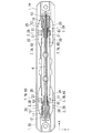
【解決手段】接続装置本体9と、接続装置本体9の一端部に形成されて配線ダクトの端部に挿入される挿入部1と、挿入部1にその両側面から突出自在となるように保持された接触子2と、接触子2を外側方に押し付ける弾性体7と、外部電線に接続される速結端子部4と、接触子2を速結端子部4に電気接続させる電気接続構造とを備えた配線ダクト接続装置において、この電気接続構造を、圧力により接点同士を押し当てる接点構造を用いて構成する。
【選択図】図1
Description
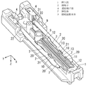
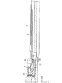
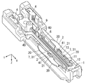
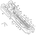
1A 第1の挿入部
1B 第2の挿入部
2 接触子
2A 第1の接触子
2B 第2の接触子
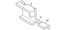
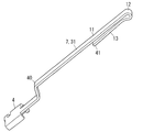
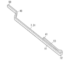
4 速結端子部
7 弾性体
7A 第1の弾性体
7B 第2の弾性体
9 接続装置本体
20 接触部
31 導電性部材
32 接点部
33 接点部
41 接点部
50 接点部
60 導電性部材
61 接点部
62 接点部
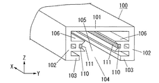
100 配線ダクト
105 コア
110 導体
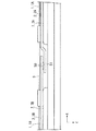
X 長手方向
Claims (7)
- 接続装置本体と、前記接続装置本体の一端部に形成されて配線ダクトの端部に挿入される挿入部と、前記挿入部にその両側面から突出自在となるように保持された接触子と、前記接触子を外側方に押し付ける弾性体と、外部電線に接続される速結端子部と、前記接触子を前記速結端子部に電気接続させる電気接続構造とを備え、前記電気接続構造は、圧力により接点同士を押し当てる接点構造から成る配線ダクト接続装置。
- 前記接触子の外側端に、長手方向に連なる複数の凸状の接触部を一体に形成した請求項1に記載の配線ダクト接続装置。
- 前記弾性体は、前記速結端子部から延長される導電性部材から成り、前記電気接続構造は、前記弾性体が有する接点部を、前記弾性体の弾性力によって前記接触子に押し当てる接点構造から成る請求項1又は2に記載の配線ダクト接続装置。
- 前記弾性体は、導電性部材から成り、前記電気接続構造は、前記弾性体が有する接点部を、前記弾性体の弾性力によって前記接触子に押し当てる接点構造と、前記弾性体が有する別の接点部を、前記速結端子部に押し当てる接点構造とから成る請求項1〜3のいずれか一項に記載の配線ダクト接続装置。
- 接続装置本体と、前記接続装置本体の一端部に形成されて配線ダクトの端部に挿入される第一の挿入部と、前記第一の挿入部にその両側面から突出自在となるように保持された第一の接触子と、前記第一の接触子を外側方に押し付ける第一の弾性体と、前記接続装置本体の他端部に形成されて別の配線ダクトの端部に挿入される第二の挿入部と、前記第二の挿入部にその両側面から突出自在となるように保持された第二の接触子と、前記第二の接触子を外側方に押し付ける第二の弾性体と、前記第一の接触子と前記第二の接触子を電気接続させる電気接続構造とを備え、前記電気接続構造は、接点同士を圧力により押し当てる接点構造から成る配線ダクト接続装置。
- 前記第一の接触子の外側端と、前記第二の接触子の外側端に、長手方向に連なる複数の凸状の接触部を一体に形成した請求項5に記載の配線ダクト接続装置。
- 前記第一の弾性体と前記第二の弾性体は、共に導電性部材から成り、前記電気接続構造は、前記第一の弾性体が有する接点部を、前記第一の弾性体の弾性力によって前記第一の接触子に押し当てる接点構造と、前記第二の弾性体が有する別の接点部を、前記第二の弾性体の弾性力によって前記第二の接触子に押し当てる接点構造とから成る請求項5又は6に記載の配線ダクト接続構造。
Priority Applications (4)
| Application Number | Priority Date | Filing Date | Title |
|---|---|---|---|
| JP2011122577A JP5895180B2 (ja) | 2011-05-31 | 2011-05-31 | 配線ダクト接続装置 |
| KR1020120056222A KR101359236B1 (ko) | 2011-05-31 | 2012-05-25 | 배선 덕트 접속 장치 |
| TW101119345A TWI445270B (zh) | 2011-05-31 | 2012-05-30 | 配線導管連接裝置 |
| CN201210173847.0A CN102810779B (zh) | 2011-05-31 | 2012-05-30 | 配线管连接装置 |
Applications Claiming Priority (1)
| Application Number | Priority Date | Filing Date | Title |
|---|---|---|---|
| JP2011122577A JP5895180B2 (ja) | 2011-05-31 | 2011-05-31 | 配線ダクト接続装置 |
Publications (2)
| Publication Number | Publication Date |
|---|---|
| JP2012252804A true JP2012252804A (ja) | 2012-12-20 |
| JP5895180B2 JP5895180B2 (ja) | 2016-03-30 |
Family
ID=47234417
Family Applications (1)
| Application Number | Title | Priority Date | Filing Date |
|---|---|---|---|
| JP2011122577A Active JP5895180B2 (ja) | 2011-05-31 | 2011-05-31 | 配線ダクト接続装置 |
Country Status (4)
| Country | Link |
|---|---|
| JP (1) | JP5895180B2 (ja) |
| KR (1) | KR101359236B1 (ja) |
| CN (1) | CN102810779B (ja) |
| TW (1) | TWI445270B (ja) |
Cited By (3)
| Publication number | Priority date | Publication date | Assignee | Title |
|---|---|---|---|---|
| TWI485945B (zh) * | 2013-03-27 | 2015-05-21 | Panasonic Corp | 絕緣架空線用連接裝置及絕緣架空電車線路系統 |
| JP2022002176A (ja) * | 2020-06-19 | 2022-01-06 | パナソニックIpマネジメント株式会社 | 端子装置及びそれを備えた配線器具 |
| WO2022113692A1 (ja) * | 2020-11-30 | 2022-06-02 | パナソニック株式会社 | Dcダクトシステム、dcダクト、給電部材及び電力供給システム |
Families Citing this family (1)
| Publication number | Priority date | Publication date | Assignee | Title |
|---|---|---|---|---|
| CN109994860B (zh) * | 2019-03-14 | 2024-06-28 | 华南农业大学 | 一种料液、电力快速互连装置 |
Citations (6)
| Publication number | Priority date | Publication date | Assignee | Title |
|---|---|---|---|---|
| JPS49146499U (ja) * | 1973-04-16 | 1974-12-18 | ||
| JPS50126994U (ja) * | 1974-03-30 | 1975-10-17 | ||
| JPS5567628U (ja) * | 1978-10-30 | 1980-05-09 | ||
| JPS55161387A (en) * | 1979-05-31 | 1980-12-15 | Matsushita Electric Works Ltd | Lighting duct connector |
| JPS6369498U (ja) * | 1986-10-27 | 1988-05-10 | ||
| JP2009283423A (ja) * | 2008-05-26 | 2009-12-03 | Panasonic Electric Works Co Ltd | 配線ダクト接続装置 |
Family Cites Families (6)
| Publication number | Priority date | Publication date | Assignee | Title |
|---|---|---|---|---|
| JPH0518220U (ja) * | 1991-08-14 | 1993-03-05 | 松下電工株式会社 | 低電圧配線装置 |
| JP2001126830A (ja) | 1999-10-22 | 2001-05-11 | Matsushita Electric Works Ltd | 配線ダクト接続装置 |
| JP2001160314A (ja) * | 1999-12-02 | 2001-06-12 | Matsushita Electric Works Ltd | 配電ダクト用プラグ |
| JP4178750B2 (ja) * | 2000-12-22 | 2008-11-12 | 松下電工株式会社 | 配線ダクト用電気接続器 |
| JP4088441B2 (ja) | 2001-12-26 | 2008-05-21 | 東芝ライテック株式会社 | 配線器具、配線装置およびライティングダクト装置 |
| JP5383248B2 (ja) * | 2009-02-25 | 2014-01-08 | パナソニック株式会社 | 配線ダクトシステム |
-
2011
- 2011-05-31 JP JP2011122577A patent/JP5895180B2/ja active Active
-
2012
- 2012-05-25 KR KR1020120056222A patent/KR101359236B1/ko active Active
- 2012-05-30 CN CN201210173847.0A patent/CN102810779B/zh active Active
- 2012-05-30 TW TW101119345A patent/TWI445270B/zh active
Patent Citations (6)
| Publication number | Priority date | Publication date | Assignee | Title |
|---|---|---|---|---|
| JPS49146499U (ja) * | 1973-04-16 | 1974-12-18 | ||
| JPS50126994U (ja) * | 1974-03-30 | 1975-10-17 | ||
| JPS5567628U (ja) * | 1978-10-30 | 1980-05-09 | ||
| JPS55161387A (en) * | 1979-05-31 | 1980-12-15 | Matsushita Electric Works Ltd | Lighting duct connector |
| JPS6369498U (ja) * | 1986-10-27 | 1988-05-10 | ||
| JP2009283423A (ja) * | 2008-05-26 | 2009-12-03 | Panasonic Electric Works Co Ltd | 配線ダクト接続装置 |
Cited By (6)
| Publication number | Priority date | Publication date | Assignee | Title |
|---|---|---|---|---|
| TWI485945B (zh) * | 2013-03-27 | 2015-05-21 | Panasonic Corp | 絕緣架空線用連接裝置及絕緣架空電車線路系統 |
| JP2022002176A (ja) * | 2020-06-19 | 2022-01-06 | パナソニックIpマネジメント株式会社 | 端子装置及びそれを備えた配線器具 |
| JP7429903B2 (ja) | 2020-06-19 | 2024-02-09 | パナソニックIpマネジメント株式会社 | 端子装置及びそれを備えた配線器具 |
| WO2022113692A1 (ja) * | 2020-11-30 | 2022-06-02 | パナソニック株式会社 | Dcダクトシステム、dcダクト、給電部材及び電力供給システム |
| JPWO2022113692A1 (ja) * | 2020-11-30 | 2022-06-02 | ||
| JP7383329B2 (ja) | 2020-11-30 | 2023-11-20 | パナソニックホールディングス株式会社 | Dcダクトシステム、dcダクト、給電部材及び電力供給システム |
Also Published As
| Publication number | Publication date |
|---|---|
| TW201320514A (zh) | 2013-05-16 |
| KR20120134038A (ko) | 2012-12-11 |
| CN102810779A (zh) | 2012-12-05 |
| JP5895180B2 (ja) | 2016-03-30 |
| CN102810779B (zh) | 2015-04-15 |
| TWI445270B (zh) | 2014-07-11 |
| KR101359236B1 (ko) | 2014-02-05 |
Similar Documents
| Publication | Publication Date | Title |
|---|---|---|
| CN105612672B (zh) | 带浮动机构的同轴连接器 | |
| CN102195175B (zh) | 插塞连接器 | |
| JP5956071B2 (ja) | 接続端子 | |
| JP6241712B2 (ja) | コネクタおよび当該コネクタに用いられるヘッダならびにソケット | |
| CN104253345B (zh) | 连接器以及在该连接器中使用的插头件及插口件 | |
| JP6128435B2 (ja) | コネクタおよび当該コネクタに用いられるヘッダならびにソケット | |
| JP2005183025A (ja) | スプリングコネクタ | |
| JP5895180B2 (ja) | 配線ダクト接続装置 | |
| US9136660B2 (en) | Female terminal | |
| JP2012186087A (ja) | コネクタ | |
| JP5081064B2 (ja) | 配線ダクト接続装置 | |
| JP5793705B2 (ja) | 配線ダクト接続装置 | |
| JP5789770B2 (ja) | 配線ダクト接続装置 | |
| JP4558406B2 (ja) | 印刷回路基板用プラグコンタクト | |
| JP2011181420A (ja) | ブレードおよびこれを用いたコネクタセット | |
| WO2012026287A1 (ja) | コネクタ構造 | |
| CN101872915B (zh) | 电连接器 | |
| JP5699283B2 (ja) | 配線ダクト接続装置 | |
| JP2008047417A (ja) | 電気コネクター用端子及び該端子をそなえた電気コネクター | |
| JP2005135833A (ja) | プラグイン接触子及びプラグイン接触子の接続構造 | |
| US20070232111A1 (en) | Card edge connector | |
| JP2005340001A (ja) | コネクタ | |
| JP2007165129A (ja) | フローティングコネクタソケット |
Legal Events
| Date | Code | Title | Description |
|---|---|---|---|
| A621 | Written request for application examination |
Free format text: JAPANESE INTERMEDIATE CODE: A621 Effective date: 20140210 |
|
| A711 | Notification of change in applicant |
Free format text: JAPANESE INTERMEDIATE CODE: A711 Effective date: 20141008 |
|
| A131 | Notification of reasons for refusal |
Free format text: JAPANESE INTERMEDIATE CODE: A131 Effective date: 20141111 |
|
| A521 | Written amendment |
Free format text: JAPANESE INTERMEDIATE CODE: A523 Effective date: 20141224 |
|
| A02 | Decision of refusal |
Free format text: JAPANESE INTERMEDIATE CODE: A02 Effective date: 20150303 |
|
| A521 | Written amendment |
Free format text: JAPANESE INTERMEDIATE CODE: A523 Effective date: 20150603 |
|
| A911 | Transfer of reconsideration by examiner before appeal (zenchi) |
Free format text: JAPANESE INTERMEDIATE CODE: A911 Effective date: 20150611 |
|
| A131 | Notification of reasons for refusal |
Free format text: JAPANESE INTERMEDIATE CODE: A131 Effective date: 20150811 |
|
| A521 | Written amendment |
Free format text: JAPANESE INTERMEDIATE CODE: A523 Effective date: 20151013 |
|
| TRDD | Decision of grant or rejection written | ||
| A01 | Written decision to grant a patent or to grant a registration (utility model) |
Free format text: JAPANESE INTERMEDIATE CODE: A01 Effective date: 20151104 |
|
| A61 | First payment of annual fees (during grant procedure) |
Free format text: JAPANESE INTERMEDIATE CODE: A61 Effective date: 20151127 |
|
| R151 | Written notification of patent or utility model registration |
Ref document number: 5895180 Country of ref document: JP Free format text: JAPANESE INTERMEDIATE CODE: R151 |