JP2012252902A - Nonaqueous electrolyte battery module - Google Patents
Nonaqueous electrolyte battery module Download PDFInfo
- Publication number
- JP2012252902A JP2012252902A JP2011125291A JP2011125291A JP2012252902A JP 2012252902 A JP2012252902 A JP 2012252902A JP 2011125291 A JP2011125291 A JP 2011125291A JP 2011125291 A JP2011125291 A JP 2011125291A JP 2012252902 A JP2012252902 A JP 2012252902A
- Authority
- JP
- Japan
- Prior art keywords
- electrolyte battery
- aqueous electrolyte
- battery module
- nonaqueous electrolyte
- battery
- Prior art date
- Legal status (The legal status is an assumption and is not a legal conclusion. Google has not performed a legal analysis and makes no representation as to the accuracy of the status listed.)
- Pending
Links
Images




Classifications
-
- Y—GENERAL TAGGING OF NEW TECHNOLOGICAL DEVELOPMENTS; GENERAL TAGGING OF CROSS-SECTIONAL TECHNOLOGIES SPANNING OVER SEVERAL SECTIONS OF THE IPC; TECHNICAL SUBJECTS COVERED BY FORMER USPC CROSS-REFERENCE ART COLLECTIONS [XRACs] AND DIGESTS
- Y02—TECHNOLOGIES OR APPLICATIONS FOR MITIGATION OR ADAPTATION AGAINST CLIMATE CHANGE
- Y02E—REDUCTION OF GREENHOUSE GAS [GHG] EMISSIONS, RELATED TO ENERGY GENERATION, TRANSMISSION OR DISTRIBUTION
- Y02E60/00—Enabling technologies; Technologies with a potential or indirect contribution to GHG emissions mitigation
- Y02E60/10—Energy storage using batteries
Landscapes
- Sealing Battery Cases Or Jackets (AREA)
- Gas Exhaust Devices For Batteries (AREA)
- Battery Mounting, Suspending (AREA)
Abstract
【課題】電池内部の燃焼により発生する発煙成分、臭気成分等を吸収でき、安全性が高い非水電解質電池モジュールを提供する。
【解決手段】本発明の非水電解質電池モジュールは、複数の非水電解質電池と、前記非水電解質電池を収納した外装体とを含み、前記非水電解質電池は、電池要素と、前記電池要素を収納した可撓性を有する外装材とを含み、前記外装材は、封止部を有し、前記非水電解質電池と前記外装体との間には、空間部と、包接化合物が充填された化合物充填部とが形成されていることを特徴とする。
【選択図】図3A non-aqueous electrolyte battery module that can absorb smoke components, odor components, and the like generated by combustion inside a battery and has high safety is provided.
A non-aqueous electrolyte battery module according to the present invention includes a plurality of non-aqueous electrolyte batteries and an outer package housing the non-aqueous electrolyte battery, and the non-aqueous electrolyte battery includes a battery element and the battery element. And the exterior material has a sealing portion, and a space portion and a clathrate compound are filled between the non-aqueous electrolyte battery and the exterior body. And a compound filling portion formed.
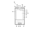
[Selection] Figure 3
Description
本発明は、可撓性を有する外装材を備えた非水電解質電池モジュールに関する。 The present invention relates to a nonaqueous electrolyte battery module provided with a flexible packaging material.
リチウムイオン二次電池に代表される非水電解質電池は、エネルギー密度が高いという特徴から、携帯電話やノート型パーソナルコンピューター等の携帯機器の電源として広く用いられている。携帯機器の高性能化に伴ってリチウムイオン二次電池の高容量化が更に進む傾向にあり、エネルギー密度を更に向上させるため、可撓性を有するラミネート外装材を用いた扁平型非水電解質電池が多く使用されている。 A non-aqueous electrolyte battery represented by a lithium ion secondary battery is widely used as a power source for portable devices such as a mobile phone and a notebook personal computer because of its high energy density. A flat non-aqueous electrolyte battery using a flexible laminate sheathing material to further improve the energy density as the capacity of the lithium ion secondary battery tends to increase further as the performance of portable devices increases. Is often used.
一方、最近では非水電解質電池の高性能化に伴い、非水電解質電池が携帯機器の電源以外の電源としても用いられようとしている。例えば、自動車用やバイク用の電源、ロボット等の移動体用の電源等に非水電解質電池が用いられ始めた。また、非水電解質電池を自動車用やバイク用の電源、ロボット等の移動体用の電源等に用いる場合には、更なる高容量化のため非水電解質電池を複数組み合わせてモジュール化して用いられる。非水電解質電池をこのようにモジュール化して用いる場合には、モジュールを構成する各非水電解質電池の安全性と、モジュール全体の安全性とが要求される。特に、非水電解質電池をこのようにモジュール化して用いると、モジュール全体として高容量、高電圧となるため、各非水電解質電池に異常が発生した場合の発煙・発火に対する対策が必要になる。 On the other hand, recently, with the improvement in performance of nonaqueous electrolyte batteries, nonaqueous electrolyte batteries are being used as power sources other than the power source of portable devices. For example, non-aqueous electrolyte batteries have begun to be used for power sources for automobiles and motorcycles, power sources for moving bodies such as robots, and the like. Further, when the nonaqueous electrolyte battery is used for a power source for automobiles or motorcycles, a power source for a moving body such as a robot, etc., it can be used in combination with a plurality of nonaqueous electrolyte batteries to further increase the capacity. . When the non-aqueous electrolyte battery is modularized in this way, the safety of each non-aqueous electrolyte battery constituting the module and the safety of the entire module are required. In particular, when the nonaqueous electrolyte battery is modularized in this manner, the module as a whole has a high capacity and a high voltage, and thus measures against smoke and ignition when an abnormality occurs in each nonaqueous electrolyte battery is required.
例えば、特許文献1には、正極と、負極と、セパレータと、非水電解液とを含む発電要素と、上記発電要素を封入するラミネートフィルム外装材と、上記外装材の外側を封止する外周熱融着部を備える二次電池と;上記外周熱融着部の少なとも一部に配置した消火剤入り容器と;上記二次電池と、消化剤入り容器を収納する筐体と;を備える電池パックが記載されている。これにより、電池内部での発火、燃焼による発熱によって消化剤入り容器が溶融することで消化剤が散布され、電池外部での燃焼を抑制する初期消火に有効であるとことが記載されている。 For example, Patent Document 1 discloses a power generation element including a positive electrode, a negative electrode, a separator, and a non-aqueous electrolyte, a laminate film exterior material that encloses the power generation element, and an outer periphery that seals the exterior of the exterior material. A secondary battery provided with a heat fusion part; a container containing a fire extinguishing agent disposed at least at a part of the outer peripheral heat fusion part; and a housing containing the secondary battery and a container containing a digestive agent. A battery pack is described. As a result, it is described that the digestive agent is dispersed by melting of the container containing the digestive agent due to the heat generated by the ignition and combustion inside the battery, which is effective for the initial fire suppression that suppresses the combustion outside the battery.
また、特許文献2には、扁平型二次電池を加圧しつつ固定するラミネートフィルム外装体と上記扁平型二次電池との間に、流体を密閉内包した流体内包袋を配置してなるモジュールにおいて、上記内包した流体は、消化作用を有する気体又は液体又は粉体又はゲルのいずれか一つであるモジュールが記載されている。これにより、扁平型二次電池が外部からの破壊的損傷を受け、発火に至った場合であっても、流体内包袋が破裂することによって消火剤が散布されるので、従来よりも、より積極的に鎮火作用を持たせることが可能となることが記載されている。 Patent Document 2 discloses a module in which a fluid-enclosed bag in which a fluid is hermetically sealed is disposed between a laminate film exterior body that pressurizes and fixes a flat-type secondary battery and the flat-type secondary battery. In addition, a module is described in which the encapsulated fluid is any one of gas, liquid, powder, or gel having digestive action. As a result, even if the flat-type secondary battery suffers destructive damage from the outside and ignites, the fire-extinguishing agent is sprayed by the bursting of the fluid encapsulating bag. It is described that it is possible to provide a fire suppression effect.
また、特許文献3には、充放電可能な電池体と、この電池体の外部にあって、上記電池体から噴出した内容物に含まれる可燃性物質を吸着するフィルタ部と、上記電池体及び上記フィルタ部を覆い、上記フィルタ部を通過することにより浄化された上記内容物を外部へ排出する排出孔が設けられた外郭部材と、上記外郭部材に圧接して上記電池体を挟み込み、この電池体に圧力をかけた状態で固定すると共に、上記電池体の熱を上記外郭部材に伝達する放熱板を備え、上記フィルタ部が、上記内容物の噴出方向を特定する噴出部近傍に対向して設けられ、上記電池体内の圧力が上昇すると、上記内容物が上記噴出部から噴出する勢いを利用して、上記フィルタ部に噴出直後の上記内容物を進入、通過させる構成とした二次電池パックが記載されている。 Patent Document 3 discloses a battery body that can be charged and discharged, a filter unit that is external to the battery body, and adsorbs combustible substances contained in the contents ejected from the battery body, the battery body, and An outer member provided with a discharge hole for covering the filter portion and discharging the contents purified by passing through the filter portion to the outside, and sandwiching the battery body in pressure contact with the outer member. The body is fixed in a state where pressure is applied, and a heat radiating plate that transmits heat of the battery body to the outer member is provided, and the filter section faces the vicinity of the ejection section that specifies the ejection direction of the contents. A secondary battery pack that is configured to allow the contents immediately after being ejected to enter and pass through the filter portion by using the momentum that the contents are ejected from the ejecting portion when the pressure in the battery body increases. Is listed To have.
これにより、保護回路の異常等により電池体のどの部分から内容物が噴出しても、まず電池体を覆う外郭部材により内容物が外郭部材内に留められ、二次電池パック外部へ漏れ出すことがない。そして、外郭部材内に留められた当該内容物に含まれる可燃性物質がフィルタ部により確実に吸着され、外郭部材に設けた排出孔から可燃性物質を含有しない内容物のみが外郭部材外部へ排出されるため、二次電池パック周囲への可燃性物質の流出を阻止し、発煙、発火を防止できることが記載されている。 As a result, even if the contents are ejected from any part of the battery body due to an abnormality of the protection circuit, the contents are first retained in the outer member by the outer member covering the battery body, and leak out of the secondary battery pack. There is no. And the combustible substance contained in the contents held in the outer member is surely adsorbed by the filter part, and only the contents not containing the combustible substance are discharged out of the outer member from the discharge hole provided in the outer member. Therefore, it is described that flammable substances can be prevented from flowing out to the periphery of the secondary battery pack, and smoke and ignition can be prevented.
しかし、特許文献1〜3では、電池外部における発煙・発火の抑制については考慮されているものの、電池内部の燃焼により発生する発煙成分、臭気成分等の抑制については何ら考慮されておらず、各電池の安全性及びモジュール全体の安全性については更に改善の余地がある。 However, in Patent Documents 1 to 3, although suppression of smoke and ignition outside the battery is considered, no consideration is given to suppression of smoke components and odor components generated by combustion inside the battery. There is room for further improvement in battery safety and overall module safety.
本発明は上記問題を解決したもので、電池内部の燃焼により発生する発煙成分、臭気成分等を吸収でき、安全性が高い非水電解質電池モジュールを提供するものである。 The present invention solves the above-described problems, and provides a non-aqueous electrolyte battery module that can absorb fuming components, odor components, and the like generated by combustion inside the battery and has high safety.
本発明の非水電解質電池モジュールは、複数の非水電解質電池と、前記非水電解質電池を収納した外装体とを含む非水電解質電池モジュールであって、前記非水電解質電池は、電池要素と、前記電池要素を収納した可撓性を有する外装材とを含み、前記外装材は、封止部を有し、前記非水電解質電池と前記外装体との間には、空間部と、包接化合物が充填された化合物充填部とが形成されていることを特徴とする。 The non-aqueous electrolyte battery module of the present invention is a non-aqueous electrolyte battery module including a plurality of non-aqueous electrolyte batteries and an exterior body housing the non-aqueous electrolyte battery, wherein the non-aqueous electrolyte battery includes a battery element and A flexible exterior material that houses the battery element, the exterior material having a sealing portion, and a space portion and a package between the nonaqueous electrolyte battery and the exterior body. A compound filling portion filled with a contact compound is formed.
本発明によると、電池内部の燃焼により発生する発煙成分、臭気成分等を吸収でき、安全性が高い非水電解質電池モジュールを提供できる。 According to the present invention, it is possible to provide a highly safe non-aqueous electrolyte battery module that can absorb smoke components, odor components, and the like generated by combustion inside the battery.
本発明の非水電解質電池モジュールは、複数の非水電解質電池と、上記非水電解質電池を収納した外装体とを備えている。また、上記非水電解質電池は、電池要素と、上記電池要素を収納した可撓性を有する外装材とを含み、上記外装材は、封止部を有している。更に、上記非水電解質電池と上記外装体との間には、空間部と、包接化合物が充填された化合物充填部とが形成されている。 The nonaqueous electrolyte battery module of the present invention includes a plurality of nonaqueous electrolyte batteries and an exterior body that houses the nonaqueous electrolyte batteries. The nonaqueous electrolyte battery includes a battery element and a flexible exterior material that houses the battery element, and the exterior material has a sealing portion. Furthermore, a space portion and a compound filling portion filled with an inclusion compound are formed between the nonaqueous electrolyte battery and the outer package.
本発明の非水電解質電池モジュールは、包接化合物が充填された化合物充填部を有しているので、非水電解質電池の内部に燃焼が発生して、発煙成分、臭気成分等が電池外に漏れ出しても、上記包接化合物が発煙成分、臭気成分等を吸収でき、モジュールの外部まで発煙成分、臭気成分等が放出されることがない。これにより、モジュールの安全性を向上できる。 Since the nonaqueous electrolyte battery module of the present invention has a compound filling portion filled with an inclusion compound, combustion occurs inside the nonaqueous electrolyte battery, and smoke components, odor components and the like are outside the battery. Even if it leaks, the inclusion compound can absorb the smoke component, odor component, etc., and the smoke component, odor component, etc. are not released to the outside of the module. Thereby, the safety | security of a module can be improved.
上記包接化合物は、その分子構造において分子サイズの空間を有する化合物であって、上記空間に他の物質の分子を取り込んで、複合体を形成し得るものであればよい。具体的には、例えば、クリタ工業社製の包接化合物“KC−103”(商品名)等が使用できる。 The inclusion compound may be a compound having a molecular size space in its molecular structure and capable of forming a complex by incorporating molecules of another substance into the space. Specifically, for example, inclusion compound “KC-103” (trade name) manufactured by Kurita Kogyo Co., Ltd. can be used.
上記包接化合物は、粉末状であることが好ましい。粉末状であると、包接化合物全体の表面積が大きくなり、発煙成分、臭気成分等の吸収効率が向上するからである。また、上記包接化合物は、比重が0.5以下であり、粒径が50μm以上3mm以下とすることができる。 The inclusion compound is preferably in the form of powder. It is because the surface area of the whole clathrate compound becomes large and the absorption efficiency of a fuming component, an odor component, etc. improves that it is a powder form. The clathrate compound may have a specific gravity of 0.5 or less and a particle size of 50 μm or more and 3 mm or less.
以下、本発明の実施形態を図面に基づき説明する。但し、図1〜図8では、同一部分には同一の符号を付し、重複した説明は省略する場合がある。 Hereinafter, embodiments of the present invention will be described with reference to the drawings. However, in FIGS. 1-8, the same code | symbol is attached | subjected to the same part and the overlapping description may be abbreviate | omitted.
先ず、本発明に用いる非水電解質電池の実施形態について扁平型リチウムイオン二次電池を例に説明する。図1Aは本実施形態で用いる電極体を説明するための斜視図であり、図1Bは電極体を外装材に収納している状態を示す斜視図であり、図1Cは電極体を外装材に収納して扁平型リチウムイオン二次電池を完成した状態の斜視図である。 First, an embodiment of a non-aqueous electrolyte battery used in the present invention will be described by taking a flat lithium ion secondary battery as an example. FIG. 1A is a perspective view for explaining an electrode body used in this embodiment, FIG. 1B is a perspective view showing a state in which the electrode body is housed in an exterior material, and FIG. 1C is an electrode body as an exterior material. It is a perspective view of the state which accommodated and completed the flat type lithium ion secondary battery.
図1Aにおいて、電池要素に含まれる電極体10は、矩形状の正極11と矩形状の負極12とを、矩形状のセパレータ13を介して積層して作製される。正極11の一端には、正極リード端子11aが設けられ、負極12の一端には、負極リード端子12aが設けられている。
In FIG. 1A, an
図1Bにおいて、可撓性を有する矩形状の外装材14は、谷折りされて第1外装面14aと第2外装面14bとから構成されている。第1外装面14aには、深絞り成形により電極収納部15が形成されている。また、各正極リード端子11a(図1A)及び各負極リード端子12a(図1A)は、それぞれ重ね合わされて溶接されて、それぞれ正極リード端子部16a及び負極リード端子部16bを形成している。
In FIG. 1B, the flexible rectangular
図1Cにおいて、電極体10は、非水電解質と共に谷折りされた第1外装面14aと第2外装面14bとが形成する電極収納部15に収納されている。また、外装材14の外周辺のうち、谷折りされた一辺以外の三辺が所定の幅をもって接合されて封止部17a、17b、17cを形成している。正極リード端子部16a及び負極リード端子部16bは、外装材14の谷折りされた一辺と対向する封止部17cから外部に引き出されている。このようにして、非水電解質電池(扁平型リチウムイオン二次電池)20が完成する。
In FIG. 1C, the
正極11は、正極活物質、正極用導電助剤、正極用バインダ等を含む混合物に、溶剤を加えて十分に混練して得た正極合剤ペーストを、正極集電体の両面に塗布して乾燥した後に、その正極合剤層を所定の厚さ及び所定の電極密度に制御することにより形成できる。
The
上記正極活物質としては、マンガンを含むスピネル構造のリチウム含有複合酸化物の単体、又はマンガンを含むスピネル構造のリチウム含有複合酸化物と他の正極活物質との混合体を用いることができる。上記マンガンを含むスピネル構造のリチウム含有複合酸化物の含有量は、正極活物質全体の質量割合で、70〜100質量%であることが好ましい。上記含有量が、70質量%を下回ると正極活物質の熱的安定性が不十分となる傾向にあるからである。 As the positive electrode active material, a spinel-structure lithium-containing composite oxide containing manganese alone or a mixture of a spinel-structure lithium-containing composite oxide containing manganese and another positive electrode active material can be used. The content of the lithium-containing composite oxide having a spinel structure containing manganese is preferably 70 to 100% by mass in terms of the mass ratio of the entire positive electrode active material. This is because if the content is less than 70% by mass, the thermal stability of the positive electrode active material tends to be insufficient.
上記マンガンを含むスピネル構造のリチウム含有複合酸化物としては、例えば、一般式LixMn2O4(0.98<x≦1.1)の組成を有するリチウム含有複合酸化物、又は上記Mnの一部がGe、Zr、Mg、Ni、Al及びCoより選ばれる少なくとも1種の元素で置換されたリチウム含有複合酸化物(例えば、LiCoMnO4、LiNi0.5Mn1.5O4等)等が挙げられる。上記マンガンを含むスピネル構造のリチウム含有複合酸化物は、1種単独で使用してもよく、2種以上を併用してもよい。 As the lithium-containing composite oxide having a spinel structure containing manganese, for example, a lithium-containing composite oxide having a composition of the general formula Li x Mn 2 O 4 (0.98 <x ≦ 1.1), or Examples thereof include lithium-containing composite oxides partially substituted with at least one element selected from Ge, Zr, Mg, Ni, Al, and Co (for example, LiCoMnO 4 , LiNi 0.5 Mn 1.5 O 4, etc.). The spinel structure lithium-containing composite oxide containing manganese may be used alone or in combination of two or more.
上記他の正極活物質としては、例えば、一般式LiCoO2に代表されるリチウムコバルト複合酸化物(構成元素の一部が、Ni、Al、Mg、Zr、Ti、B等の元素で置換された複合酸化物も含む。)、一般式LiNiO2、Li1+xNi0.7Co0.25Al0.05O2等に代表されるリチウムニッケル複合酸化物(構成元素の一部が、Co、Al、Mg、Zr、Ti、B等の元素で置換された複合酸化物も含む。)等の層状構造の複合酸化物;一般式Li4Ti5O12に代表されるリチウムチタン複合酸化物(構成元素の一部が、Ni、Co、Al、Mg、Zr、B等の元素で置換された複合酸化物も含む。)等のスピネル構造の複合酸化物;一般式LiMPO4に代表されるオリビン構造のリチウム複合酸化物(但し、MはNi、Co及びFeより選ばれる少なくとも1種)等が例示される。 As the other positive electrode active material, for example, a lithium cobalt composite oxide typified by a general formula LiCoO 2 (a part of the constituent elements is substituted with an element such as Ni, Al, Mg, Zr, Ti, B, etc. Composite oxides are also included.), Lithium nickel composite oxides represented by general formulas LiNiO 2 , Li 1 + x Ni 0.7 Co 0.25 Al 0.05 O 2 and the like (some of the constituent elements are Co, Al, Mg, Zr) , Including composite oxides substituted with elements such as Ti, B, etc.); lithium titanium composite oxides represented by the general formula Li 4 Ti 5 O 12 (part of constituent elements) Including complex oxides substituted with elements such as Ni, Co, Al, Mg, Zr, and B.) Complex oxides of spinel structure such as: Lithium complex oxidation of olivine structure represented by general formula LiMPO 4 Thing (however, M is Ni, Co and F and at least one selected from e).
上記正極用導電助剤は、正極合剤層の導電性向上等の目的で必要に応じて添加すればよく、通常は導電性粉末が用いられる。上記導電性粉末としては、例えば、カーボンブラック、ケッチェンブラック、アセチレンブラック、繊維状炭素、黒鉛等の炭素粉末や、ニッケル粉末等の金属粉末を利用することができる。 What is necessary is just to add the said conductive support agent for positive electrodes as needed for the objective, such as the electroconductivity improvement of a positive mix layer, and a conductive powder is normally used. Examples of the conductive powder include carbon powder such as carbon black, ketjen black, acetylene black, fibrous carbon, and graphite, and metal powder such as nickel powder.
上記正極用バインダには、ポリフッ化ビニリデン(PVDF)、ポリテトラフルオロエチレン(PTFE)等が挙げられるが、これらに限定されるものではない。 Examples of the positive electrode binder include, but are not limited to, polyvinylidene fluoride (PVDF) and polytetrafluoroethylene (PTFE).
上記正極集電体としては、構成された電池において実質的に化学的に安定な電子伝導体であれば特に限定されない。正極集電体としては、例えば、厚さが10〜30μmのアルミニウム箔等が用いられる。 The positive electrode current collector is not particularly limited as long as it is an electron conductor that is substantially chemically stable in the battery. As the positive electrode current collector, for example, an aluminum foil having a thickness of 10 to 30 μm is used.
上記溶剤としては、例えば、N−メチル−2−ピロリドン等が使用できる。 As the solvent, for example, N-methyl-2-pyrrolidone or the like can be used.
正極11の厚さは特に限定されないが、通常は110〜230μmである。
Although the thickness of the
負極12は、負極活物質、負極用導電助剤、負極用バインダ等を含む混合物に、溶剤を加えて十分に混練して得た負極合剤ペーストを、負極集電体の両面に塗布して乾燥した後に、その負極合剤層を所定の厚さ及び所定の電極密度に制御することにより形成できる。
The
上記負極活物質としては、例えば、天然黒鉛又は塊状黒鉛、鱗片状黒鉛、土状黒鉛等の人造黒鉛等の炭素材料が用いられるが、リチウムイオンを吸蔵・放出可能であればこれらに限定はされない。 Examples of the negative electrode active material include carbon materials such as natural graphite or artificial graphite such as massive graphite, flaky graphite, and earthy graphite, but are not limited thereto as long as lithium ions can be occluded / released. .
上記負極集電体としては、構成された電池において実質的に化学的に安定な電子伝導体であれば特に限定されない。負極集電体としては、例えば、厚さが5〜20μmの銅箔等が用いられる。 The negative electrode current collector is not particularly limited as long as it is an electron conductor that is substantially chemically stable in the constituted battery. As the negative electrode current collector, for example, a copper foil having a thickness of 5 to 20 μm is used.
上記負極用導電助剤、負極用バインダ、溶剤については、正極に用いたものと同様のものを使用できる。 About the said conductive additive for negative electrodes, the binder for negative electrodes, and a solvent, the thing similar to what was used for the positive electrode can be used.
負極12の厚さは特に限定されないが、通常は65〜220μmである。
Although the thickness of the
セパレータ13としては、厚さが10〜50μmの耐熱性多孔質基体と、厚さが10〜30μmの熱可塑性樹脂からなる微多孔フィルムとを備えた2層構造のセパレータを用いることができる。耐熱性多孔質基体としては、例えば、耐熱温度が150℃以上の繊維状物で形成してもよく、上記繊維状物は、セルロース及びその変成体、ポリオレフィン、ポリエステル、ポリアクリロニトリル、アラミド、ポリアミドイミド及びポリイミドよりなる群から選択される少なくとも1種の材料で形成することができ、より具体的には上記材料からなる織布、不織布(紙を含む。)等のシート状物を耐熱性多孔質基体として用いることができる。
As the
また、上記熱可塑性樹脂からなる微多孔フィルムとしては、一定温度以上(100〜140℃)で微孔を閉塞し、抵抗を上げるシャットダウン機能をセパレータに付与するために、例えば、融点が80〜140℃である熱可塑性樹脂からなる微多孔フィルムを用いることができる。より具体的には、耐有機溶剤性及び疎水性を有するポリプロピレン、ポリエチレン等のオレフィン系ポリマーからなる微多孔シートを用いることができる。 In addition, the microporous film made of the thermoplastic resin has a melting point of, for example, 80 to 140 in order to provide the separator with a shutdown function that closes the micropores at a certain temperature or higher (100 to 140 ° C.) and increases the resistance. A microporous film made of a thermoplastic resin at a temperature of ° C can be used. More specifically, a microporous sheet made of an olefin polymer such as polypropylene and polyethylene having resistance to organic solvents and hydrophobicity can be used.
セパレータ13の厚さは特に限定されないが、通常は25〜90μmである。
Although the thickness of the
外装材14としては、アルミニウム等の金属層と熱可塑性樹脂層とが積層されたラミネートフィルム等を用いることができる。例えば、厚さが20〜100μmのアルミニウム層の外側に厚さが20〜50μmの熱可塑性樹脂層を設け、そのアルミニウム層の内側に20〜100μmの接着層を設けたラミネートフィルムを用いることができる。これにより、封止部17a、17b、17cは、熱溶着により確実に接合できる。
As the
外装材14の厚さは特に限定されないが、通常は60〜250μmである。
Although the thickness of the
上記非水電解質としては、有機溶媒にリチウム塩を溶解させた非水電解液を使用することができる。 As the non-aqueous electrolyte, a non-aqueous electrolyte solution in which a lithium salt is dissolved in an organic solvent can be used.
上記有機溶媒としては、例えば、ビニレンカーボネート(VC)、プロピレンカーボネート(PC)、エチレンカーボネート(EC)、ブチレンカーボネート(BC)、ジメチルカーボネート(DMC)、ジエチルカーボネート(DEC)、メチルエチルカーボネート(MEC)、γ−ブチロラクトン等の有機溶媒を1種類又は2種類以上混合して用いることができる。また、上記リチウム塩としては、例えば、LiClO4、LiPF6、LiBF4、LiAsF6、LiSbF6、LiCF3SO3等から選ばれる少なくとも1種類のリチウム塩を用いることができる。非水電解液中のLiイオンの濃度は、0.5〜1.5mol/Lとすればよい。 Examples of the organic solvent include vinylene carbonate (VC), propylene carbonate (PC), ethylene carbonate (EC), butylene carbonate (BC), dimethyl carbonate (DMC), diethyl carbonate (DEC), and methyl ethyl carbonate (MEC). , Γ-butyrolactone or other organic solvents can be used alone or in combination. Furthermore, as the lithium salt, for example, it can be used at least one lithium salt selected from LiClO 4, LiPF 6, LiBF 4 , LiAsF 6, LiSbF 6, LiCF 3 SO 3 and the like. The concentration of Li ions in the nonaqueous electrolytic solution may be 0.5 to 1.5 mol / L.
次に、本発明の非水電解質電池モジュールの実施形態について説明する。本実施形態の非水電解質電池モジュールは、上記非水電解質電池を複数積層して外装体に挿入したものである。 Next, an embodiment of the nonaqueous electrolyte battery module of the present invention will be described. The nonaqueous electrolyte battery module of the present embodiment is obtained by stacking a plurality of the above nonaqueous electrolyte batteries and inserting them into an outer package.
図2は、本実施形態の非水電解質電池モジュールの断面図である。図2において、非水電解質電池モジュール50の外装体40の内部には、非水電解質電池20が5個積層されて収納されている。非水電解質電池20は、放熱シート(図示せず。)を介して積層してもよい。また、非水電解質電池20と外装体40との間には、空間部30が形成されている。但し、図2では、図面の理解を容易にするため、非水電解質電池20については、断面を示すハッチングを省略している。
FIG. 2 is a cross-sectional view of the nonaqueous electrolyte battery module of the present embodiment. In FIG. 2, five
図3は、図2のI−I線の断面図である。図3において、空間部30は、非水電解質電池20と外装体40との間の、非水電解質電池20の封止部17a、17b、17cの部分に形成されている。また、非水電解質電池20の外装材14の外周辺のうち、谷折された一辺側の、非水電解質電池20と外装体40との間には、化合物充填部41が形成され、化合物充填部41には包接化合物35が充填されている。
3 is a cross-sectional view taken along the line II of FIG. In FIG. 3, the
図3において、外装体40は、開口部42を備え、開口部42には、封止樹脂31が充填されている。封止樹脂31としては、例えば、ウレタン樹脂、エポキシ樹脂、ユリア樹脂、フェノール樹脂等を使用できる。また、各非水電解質電池20の正極リード端子16a及び負極リード端子16bは、例えば直列にそれぞれ接続されて正極外部端子19a及び負極外部端子19bとして外部に引き出されている。
In FIG. 3, the
ここで、何らかの異常により非水電解質電池20の内部が燃焼状態に至ると、電池内圧が上昇して封止部17a、17b、17cのいずれかの部分が開裂して、電池内部から発煙成分、臭気成分等が放出される場合がある。その場合、空間部30は、その発煙成分、臭気成分等を包接化合物35が充填された化合物充填部41へ導入する排気通路となる。これにより、電池内部から放出された発煙成分、臭気成分等を包接化合物35が充填された化合物充填部41で吸収することができ、外装体40の外部まで発煙成分、臭気成分等が放出されることがなく、モジュールの安全性を向上できる。
Here, when the inside of the
図4は、本実施形態の非水電解質電池モジュールの外観斜視図である。本実施形態の非水電解質電池モジュール50を作製するには、外装体40の内部に、包接化合物35及び非水電解質電池20を配置した後に、封止樹脂31を充填して硬化させればよい。
FIG. 4 is an external perspective view of the nonaqueous electrolyte battery module of the present embodiment. In order to fabricate the nonaqueous
図5は、本発明の非水電解質電池モジュールの他の形態を示す上記実施形態の図3に対応する図である。図5の形態では、化合物充填部41の底面に排気孔43を設け、更に排気孔43を覆うようにフィルタ44を配置した以外は、図3に示した実施形態と同様である。何らかの異常により非水電解質電池20の内部が燃焼状態に至り、電池内圧が上昇して封止部17a、17b、17cのいずれかの部分が開裂して、電池内部から発煙成分、臭気成分等が放出されると、放出された発煙成分、臭気成分等は、一旦包接化合物35に吸収されるが、化合物充填部41には、排気孔43とフィルタ44が備えられているので、包接化合物35に吸収されなかったガス等は、フィルタ44を介して排気孔43からモジュールの外部へ排出される。これにより、モジュール内の内圧上昇による外装体40の破裂等の発生を確実に防止でき、非水電解質電池モジュール50の安全性を向上できる。また、排気孔43はフィルタ44で覆われているので、包接化合物35がモジュールの外部に放出されることはない。
FIG. 5 is a view corresponding to FIG. 3 of the above embodiment showing another embodiment of the nonaqueous electrolyte battery module of the present invention. 5 is the same as the embodiment shown in FIG. 3 except that an
フィルタ44の材質は特に限定されないが、不織布等が使用できる。また、フィルタ44の細孔径は包接化合物35の粒径未満であることが好ましい。例えば、包接化合物35の粒径が50μm以上の場合は、フィルタ44の細孔径は50μm未満であることが好ましい。これにより、包接化合物35のモジュール外部への放出を確実に防止できる。
Although the material of the
また、排気孔43の大きさも特に限定されないが、通常は孔径が1〜2mm程度の大きさとすればよい。
Also, the size of the
図6は、本発明の非水電解質電池モジュールの更に他の形態を示す上記実施形態の図3に対応する図である。図6の形態では、排気孔43に逆止弁45を設置した以外は、図5に示した実施形態と同様である。逆止弁45は、モジュール内部から外部へガス等を放出可能であるが、モジュール外部から内部への空気等の流入を防止する機能を有している。本実施形態では、排気孔43に逆止弁45を設置しているので、モジュール内部のガス等をモジュール外部へ放出できると共に、モジュール外部から内部への空気等の流入を防止できる。
FIG. 6 is a view corresponding to FIG. 3 of the above embodiment showing still another embodiment of the nonaqueous electrolyte battery module of the present invention. 6 is the same as the embodiment shown in FIG. 5 except that a check valve 45 is provided in the
図7は、本発明の非水電解質電池モジュールの更に他の形態を示す上記実施形態の図3に対応する図である。図7の形態では、化合物充填部41にバッフル板46を設置した以外は、図5に示した実施形態と同様である。バッフル板46を設置することにより、化合物充填部41内における、電池内部から放出された発煙成分、臭気成分等の流路を長くすることができる。これにより、上記発煙成分、臭気成分等の包接化合物35への吸収効率を向上できる。本実施形態では、排気孔43に前述の逆止弁45(図6)を更に設置してもよい。
FIG. 7 is a view corresponding to FIG. 3 of the above embodiment showing still another embodiment of the nonaqueous electrolyte battery module of the present invention. 7 is the same as the embodiment shown in FIG. 5 except that a
図8は、本発明の非水電解質電池モジュールの更に他の形態を示す上記実施形態の図3に対応する図である。図8の形態では、排気孔43にエアバック47を設置した以外は、図5に示した実施形態と同様である。エアバック47を設置することにより、包接化合物35に吸収されず、フィルタ44を透過したガス等を捕集することができる。
FIG. 8 is a view corresponding to FIG. 3 of the above embodiment showing still another embodiment of the nonaqueous electrolyte battery module of the present invention. 8 is the same as the embodiment shown in FIG. 5 except that an
以上説明したように、本発明は、電池内部の燃焼により発生する発煙成分、臭気成分等を吸収でき、安全性が高い非水電解質電池モジュールを提供できる。従って、本発明の非水電解質電池モジュールは、高い安全性が要求される自動車用やバイク用の電源、ロボット等の移動体用の電源等として広く利用できる。 As described above, the present invention can provide a non-aqueous electrolyte battery module that can absorb smoke components, odor components, and the like generated by combustion inside the battery and has high safety. Therefore, the non-aqueous electrolyte battery module of the present invention can be widely used as a power source for automobiles or motorcycles that require high safety, a power source for moving bodies such as robots, and the like.
10 電極体
11 正極
11a 正極リード端子
12 負極
12a 負極リード端子
13 セパレータ
14 外装材
14a 第1外装面
14b 第2外装面
15 電極収納部
16a 正極リード端子部
16b 負極リード端子部
17a、17b、17c 封止部
19a 正極外部端子
19b 負極外部端子
20 非水電解質電池
30 空間部
31 封止樹脂
35 包接化合物
40 外装体
41 化合物充填部
42 開口部
43 排気孔
44 フィルタ
45 逆止弁
46 バッフル板
47 エアバック
50 非水電解質電池モジュール
DESCRIPTION OF
Claims (8)
前記非水電解質電池は、電池要素と、前記電池要素を収納した可撓性を有する外装材とを含み、
前記外装材は、封止部を有し、
前記非水電解質電池と前記外装体との間には、空間部と、包接化合物が充填された化合物充填部とが形成されていることを特徴とする非水電解質電池モジュール。 A non-aqueous electrolyte battery module comprising a plurality of non-aqueous electrolyte batteries and an exterior body containing the non-aqueous electrolyte batteries,
The non-aqueous electrolyte battery includes a battery element and a flexible exterior material that houses the battery element,
The exterior material has a sealing portion,
A space part and a compound filling part filled with an inclusion compound are formed between the non-aqueous electrolyte battery and the exterior body.
前記外装材の外周辺のうち、谷折りされた一辺以外の三辺が所定の幅をもって接合されて前記封止部を形成し、
前記谷折りされた一辺と対向する辺に形成された前記封止部から電極リード端子部が引き出され、
前記化合物充填部は、前記非水電解質電池の前記谷折りされた一辺側に配置され、
前記外装体は、前記非水電解質電池の前記電極リード端子部が配置された側に開口部を備え、
前記開口部は、封止樹脂により封止されている請求項1〜3のいずれか1項に記載の非水電解質電池モジュール。 The exterior material is folded into a rectangular shape,
Of the outer periphery of the exterior material, three sides other than the one side folded in the valley are joined with a predetermined width to form the sealing portion,
The electrode lead terminal portion is drawn out from the sealing portion formed on the side facing the one side that is folded at the valley,
The compound filling portion is disposed on the side of the non-aqueous electrolyte battery that is folded in the valley,
The exterior body includes an opening on the side where the electrode lead terminal portion of the nonaqueous electrolyte battery is disposed,
The non-aqueous electrolyte battery module according to claim 1, wherein the opening is sealed with a sealing resin.
前記排気孔には、フィルタが配置され、
前記フィルタの細孔径が、50μm未満である請求項4に記載の非水電解質電池モジュール。 The exterior body includes an exhaust hole that communicates the compound filling portion with the outside,
A filter is disposed in the exhaust hole,
The nonaqueous electrolyte battery module according to claim 4, wherein a pore diameter of the filter is less than 50 μm.
Priority Applications (1)
| Application Number | Priority Date | Filing Date | Title |
|---|---|---|---|
| JP2011125291A JP2012252902A (en) | 2011-06-03 | 2011-06-03 | Nonaqueous electrolyte battery module |
Applications Claiming Priority (1)
| Application Number | Priority Date | Filing Date | Title |
|---|---|---|---|
| JP2011125291A JP2012252902A (en) | 2011-06-03 | 2011-06-03 | Nonaqueous electrolyte battery module |
Publications (1)
| Publication Number | Publication Date |
|---|---|
| JP2012252902A true JP2012252902A (en) | 2012-12-20 |
Family
ID=47525533
Family Applications (1)
| Application Number | Title | Priority Date | Filing Date |
|---|---|---|---|
| JP2011125291A Pending JP2012252902A (en) | 2011-06-03 | 2011-06-03 | Nonaqueous electrolyte battery module |
Country Status (1)
| Country | Link |
|---|---|
| JP (1) | JP2012252902A (en) |
Cited By (5)
| Publication number | Priority date | Publication date | Assignee | Title |
|---|---|---|---|---|
| WO2015008341A1 (en) * | 2013-07-17 | 2015-01-22 | 株式会社 日立製作所 | Secondary battery module and battery system |
| WO2016009989A1 (en) * | 2014-07-14 | 2016-01-21 | 株式会社カネカ | Cell pack and power storage unit including plurality of same |
| CN113488729A (en) * | 2020-07-31 | 2021-10-08 | 惠州市合盈科技有限公司 | Lithium battery with flame retardant effect |
| WO2025205100A1 (en) * | 2024-03-25 | 2025-10-02 | オルガノ株式会社 | Battery accommodation body, battery module, and battery pack |
| JP2026505863A (en) * | 2023-02-16 | 2026-02-18 | エーヴィエル・リスト・ゲーエムベーハー | Battery Storage Device |
Citations (5)
| Publication number | Priority date | Publication date | Assignee | Title |
|---|---|---|---|---|
| JP2006228610A (en) * | 2005-02-18 | 2006-08-31 | Densei Lambda Kk | Secondary battery pack |
| JP2007103162A (en) * | 2005-10-04 | 2007-04-19 | Densei Lambda Kk | Battery pack |
| JP2007194001A (en) * | 2006-01-18 | 2007-08-02 | Matsushita Electric Ind Co Ltd | Battery application equipment |
| JP2008226560A (en) * | 2007-03-09 | 2008-09-25 | Gs Yuasa Corporation:Kk | Battery pack |
| JP2009099322A (en) * | 2007-10-15 | 2009-05-07 | Sharp Corp | Battery pack |
-
2011
- 2011-06-03 JP JP2011125291A patent/JP2012252902A/en active Pending
Patent Citations (5)
| Publication number | Priority date | Publication date | Assignee | Title |
|---|---|---|---|---|
| JP2006228610A (en) * | 2005-02-18 | 2006-08-31 | Densei Lambda Kk | Secondary battery pack |
| JP2007103162A (en) * | 2005-10-04 | 2007-04-19 | Densei Lambda Kk | Battery pack |
| JP2007194001A (en) * | 2006-01-18 | 2007-08-02 | Matsushita Electric Ind Co Ltd | Battery application equipment |
| JP2008226560A (en) * | 2007-03-09 | 2008-09-25 | Gs Yuasa Corporation:Kk | Battery pack |
| JP2009099322A (en) * | 2007-10-15 | 2009-05-07 | Sharp Corp | Battery pack |
Cited By (5)
| Publication number | Priority date | Publication date | Assignee | Title |
|---|---|---|---|---|
| WO2015008341A1 (en) * | 2013-07-17 | 2015-01-22 | 株式会社 日立製作所 | Secondary battery module and battery system |
| WO2016009989A1 (en) * | 2014-07-14 | 2016-01-21 | 株式会社カネカ | Cell pack and power storage unit including plurality of same |
| CN113488729A (en) * | 2020-07-31 | 2021-10-08 | 惠州市合盈科技有限公司 | Lithium battery with flame retardant effect |
| JP2026505863A (en) * | 2023-02-16 | 2026-02-18 | エーヴィエル・リスト・ゲーエムベーハー | Battery Storage Device |
| WO2025205100A1 (en) * | 2024-03-25 | 2025-10-02 | オルガノ株式会社 | Battery accommodation body, battery module, and battery pack |
Similar Documents
| Publication | Publication Date | Title |
|---|---|---|
| JP5451694B2 (en) | Non-aqueous electrolyte battery module | |
| JP5449695B2 (en) | Assembled battery | |
| JP5592819B2 (en) | Non-aqueous electrolyte battery module | |
| JP5094215B2 (en) | Battery and battery pack | |
| JP6556256B2 (en) | Pouch-type secondary battery including safety member | |
| US8309250B2 (en) | Battery having fire extinguishing element in mesh form | |
| US20110244304A1 (en) | Stack type battery | |
| CN207818629U (en) | Pouch type secondary battery | |
| EP3279976A1 (en) | Sealed battery and battery pack | |
| WO2014119308A1 (en) | Sealed battery | |
| JP2009099322A (en) | Battery pack | |
| CN107925137A (en) | Battery cell including electrode leads containing gas sorbent | |
| JP2012113875A (en) | Nonaqueous electrolyte battery module | |
| JP2019087336A (en) | Secondary battery | |
| JP2011090929A (en) | Secondary battery | |
| JP6783146B2 (en) | Electrodes and lithium-ion secondary batteries using them | |
| JP3583592B2 (en) | Thin rechargeable battery | |
| JP2013051121A (en) | Nonaqueous electrolyte battery module | |
| JP2004158344A (en) | Laminated secondary battery, assembled battery module including a plurality of laminated secondary batteries, assembled battery including a plurality of assembled battery modules, and electric vehicle equipped with any one of these batteries | |
| JP4103471B2 (en) | Laminated battery and vehicle equipped with the same | |
| JP3579227B2 (en) | Thin rechargeable battery | |
| JP2012064459A (en) | Nonaqueous electrolyte battery | |
| JP5201557B2 (en) | Nonaqueous electrolyte battery and nonaqueous electrolyte battery module | |
| JP6941796B2 (en) | Non-aqueous electrolyte secondary battery | |
| JP2007087652A (en) | Nonaqueous electrolyte battery |
Legal Events
| Date | Code | Title | Description |
|---|---|---|---|
| A711 | Notification of change in applicant |
Free format text: JAPANESE INTERMEDIATE CODE: A712 Effective date: 20130123 |
|
| A621 | Written request for application examination |
Free format text: JAPANESE INTERMEDIATE CODE: A621 Effective date: 20140120 |
|
| A977 | Report on retrieval |
Free format text: JAPANESE INTERMEDIATE CODE: A971007 Effective date: 20140521 |
|
| A131 | Notification of reasons for refusal |
Free format text: JAPANESE INTERMEDIATE CODE: A131 Effective date: 20140605 |
|
| A02 | Decision of refusal |
Free format text: JAPANESE INTERMEDIATE CODE: A02 Effective date: 20141009 |