JP2012253902A - Method and device for changing electric power system model - Google Patents
Method and device for changing electric power system model Download PDFInfo
- Publication number
- JP2012253902A JP2012253902A JP2011124479A JP2011124479A JP2012253902A JP 2012253902 A JP2012253902 A JP 2012253902A JP 2011124479 A JP2011124479 A JP 2011124479A JP 2011124479 A JP2011124479 A JP 2011124479A JP 2012253902 A JP2012253902 A JP 2012253902A
- Authority
- JP
- Japan
- Prior art keywords
- power system
- equipment
- changed
- system model
- facilities
- Prior art date
- Legal status (The legal status is an assumption and is not a legal conclusion. Google has not performed a legal analysis and makes no representation as to the accuracy of the status listed.)
- Pending
Links
Images

Landscapes
- Supply And Distribution Of Alternating Current (AREA)
Abstract
【課題】簡易な方法で訓練用の単結図を変更する。
【解決手段】母線およびブランチを含む設備を、複数有する電力系統のモデルである基本系統モデルの構成を変更する訓練用系統データ生成装置1において、入力部30を介して、電力系統モデルにおいて変更対象となる複数の設備の情報や、変更後における当該設備の線路定数が、擬似オフラインデータとして入力され、変更対象となる複数の設備を、擬似オフラインデータにおける線路定数を有する1つの設備に置き換えることで、前記変更対象となる複数の設備を変更することを特徴とする。また、設備の変更とは、直列的あるいは並列的に配置されている設備の縮約や、ダミー設備への変換であることを特徴とする。
【選択図】図1A simple diagram for training is changed by a simple method.
In a system data generator for training 1 that changes the configuration of a basic system model that is a model of an electric power system having a plurality of facilities including busbars and branches, an object to be changed in the power system model via an input unit 30. By replacing the information on the plurality of facilities and the line constant of the facility after the change as pseudo-offline data, and replacing the plurality of facilities to be changed with one facility having the line constant in the pseudo-offline data. The plurality of facilities to be changed are changed. The change of equipment is characterized by contraction of equipment arranged in series or in parallel or conversion to dummy equipment.
[Selection] Figure 1
Description
本発明は、訓練用の電力系統のモデルの変更を行う電力系統モデル変更方法および電力系統モデル変更装置の技術に関する。 The present invention relates to a technique of a power system model changing method and a power system model changing apparatus for changing a model of a power system for training.
電力系統の給電運用業務は、電圧階級に応じて中央給電指令所、基幹給電所、給電制御所のそれぞれにおいて、監視・制御業務を行っている。
そして、中央給電指令所、基幹給電所、給電制御所のそれぞれにおいて、実際の運用にあった電力系統で単線結線図(以下、単結図と称する)のデータを生成し、この単結図を用いて監視・制御業務を行っている。このような単結図は、平常時の系統操作の状況確認はもちろんのこと、事故時の状態把握やその事故に対する復旧操作を的確に判断することにも用いる。
The power supply operation of the power system is monitored and controlled at each of the central power supply command station, the main power supply station, and the power supply control station according to the voltage class.
Then, in each of the central power supply command station, the main power supply station, and the power supply control station, data of a single-line connection diagram (hereinafter referred to as a single connection diagram) is generated with the power system that is in actual operation, and this single connection diagram is generated. It is used for monitoring and control work. Such a single diagram is used not only for confirming the status of system operation during normal times, but also for grasping the state at the time of an accident and accurately determining the recovery operation for the accident.
特許文献1には、電力系統における各設備間の任意の接続に対応し、かつ潮流計算の処理性能を向上できる系統モデル作成方法、潮流計算装置およびそのプログラムが開示されている。 Patent Document 1 discloses a system model creation method, a power flow calculation device, and a program thereof that can cope with any connection between facilities in an electric power system and can improve the processing performance of power flow calculation.
ところで、近年、電力系統の監視・制御業務の自由化などにより、平常時の系統操作に対する訓練や故障時の系統操作への的確さが運用者に求められてきている。
通常、電力系統の監視・制御の訓練業務を行うためのシステムは、実際の電力系統(以下、実電力系統と称する)における給電運用業務を行うための運用系システムとは分離されている。
By the way, in recent years, due to the liberalization of power system monitoring and control work, etc., operators have been required to be trained in normal system operation and accurate in system operation at the time of failure.
In general, a system for performing training work for monitoring and controlling the power system is separated from an operation system for performing power supply operation work in an actual power system (hereinafter referred to as an actual power system).
ここで、電力系統のメンテナンスにはオフラインメンテナンスと、オンラインメンテナンスとがある。
オフラインメンテナンスとは、実電力系統とは接続していないメンテナンス用の端末で行われるメンテナンスであり、メンテナンスの結果は、システム内のサーバに送られた後、システム内のデータに反映されるメンテナンスである。そして、オンラインメンテナンスとは、システム中のサーバなどで行われ、メンテナンスの結果がすぐにシステム内に反映されるメンテナンスである。オンラインメンテナンスは監視対象の変更など、小さな変更を伴うメンテナンスに使用され、オフラインメンテナンスは実電力系統の母線構造の変更などに合わせて行い、大きな変更を伴うメンテナンスに使用される。
Here, there are offline maintenance and online maintenance in power system maintenance.
Offline maintenance is maintenance performed on a maintenance terminal that is not connected to the actual power system, and the result of the maintenance is reflected in the data in the system after it is sent to the server in the system. is there. The online maintenance is a maintenance performed on a server in the system and the result of the maintenance is immediately reflected in the system. Online maintenance is used for maintenance with small changes such as monitoring changes, and offline maintenance is performed according to changes in the bus structure of the actual power system and used for maintenance with large changes.
従来の訓練業務用システムには、オンラインメンテナンスを行うための処理が用意されているが、訓練用のオフラインメンテナンスを行うための処理が用意されていない。つまり、訓練用の電力系統の構成を大きく変更するための方法が用意されていない。
そこで、従来の訓練業務用システムでは、運用系のオフラインメンテナンスの結果を、訓練業務用システムに反映させることで、訓練用の電力系統にオフラインメンテナンスを行う方法が行われている。しかしながら、このような方法では、手間がかかるため、ユーザの負担が大きくなるという問題がある。また、将来使用される予定の電力系統や、実電力系統を改良した電力系統や、新しく作成した電力系統など実電力系統とは異なる電力系統での訓練が困難である。
In the conventional training business system, a process for performing online maintenance is prepared, but a process for performing offline maintenance for training is not prepared. That is, a method for greatly changing the configuration of the power system for training is not prepared.
Therefore, in the conventional training business system, a method of performing offline maintenance on the training power system is performed by reflecting the result of the operational offline maintenance in the training business system. However, such a method is troublesome, and there is a problem that the burden on the user increases. In addition, it is difficult to train in a power system that is different from the actual power system, such as a power system scheduled to be used in the future, a power system improved from the actual power system, or a newly created power system.
なお、特許文献1には、設備をまとめる旨の記載や、DC(Direct Current)不要設備を省略する旨の記載がある。しかしながら、設備をまとめる手法については、その具体的な手法が記載されておらず、DC不要設備を省略する手法については、装置側ですべてのノードを検索し、装置側がDC不要設備を判定するため、設定および処理が複雑になるという問題がある。 Note that Patent Document 1 includes a description that the facilities are gathered and a description that a DC (Direct Current) unnecessary facility is omitted. However, no specific method is described for the method of organizing facilities, and for the method of omitting DC unnecessary facilities, all nodes are searched on the device side, and the device side determines DC unnecessary facilities. There is a problem that the setting and processing become complicated.
このような背景に鑑みて本発明がなされたのであり、本発明は、簡易な方法で訓練用の単結図を変更することを目的とする。 The present invention has been made in view of such a background, and an object of the present invention is to change a single diagram for training by a simple method.
前記課題を解決するため、本発明は、母線およびブランチを含む設備を、複数有する電力系統のモデルである電力系統モデルの構成を変更する電力系統モデル変更装置による電力系統モデル変更方法であって、前記電力系統モデル変更装置は、入力部を介して、前記電力系統モデルにおいて変更対象となる複数の設備の情報および変更後における当該設備の属性情報が入力され、前記変更対象となる複数の設備を、前記属性情報を有する1つの設備に置き換えることで、前記変更対象となる複数の設備を変更することを特徴とする。
その他の解決手段については、実施形態中にて適宜説明する。
In order to solve the above problems, the present invention is a power system model changing method by a power system model changing device that changes the configuration of a power system model that is a model of a power system having a plurality of facilities including busbars and branches, The power system model changing device receives, via the input unit, information on a plurality of facilities to be changed in the power system model and attribute information on the equipment after the change, and the plurality of facilities to be changed. The plurality of facilities to be changed are changed by replacing with one facility having the attribute information.
Other solutions will be described as appropriate in the embodiments.
本発明によれば、簡易な方法で訓練用の単結図を変更することができる。 According to the present invention, a single figure for training can be changed by a simple method.
次に、本発明を実施するための形態(「実施形態」という)について、適宜図面を参照しながら詳細に説明する。 Next, modes for carrying out the present invention (referred to as “embodiments”) will be described in detail with reference to the drawings as appropriate.
《システム構成》
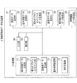
図1は、本実施形態に係る訓練用系統データ生成装置の構成例を示す図である。
訓練用系統データ生成装置(電力系統モデル変更装置)1は、処理部10と、設備データ記憶部21と、基本系統データ記憶部22と、擬似オフラインメンテナンスデータ記憶部23と、変更用データ記憶部24と、変更基本系統データ記憶部25と、開閉機器データ記憶部26と、入力部30と、表示部40とを有する。
さらに、処理部10は基本系統データ生成部11と、擬似オフラインメンテナンス部12と、変更用データ生成部13と、基本系統変更部(電力系統変更部)14と、解析計算部15とを有する。
"System configuration"
FIG. 1 is a diagram illustrating a configuration example of a training system data generation device according to the present embodiment.
A training system data generation device (power system model change device) 1 includes a processing unit 10, an equipment
The processing unit 10 further includes a basic system
基本系統データ生成部11は、入力部30を介して入力された情報を基に、設備データから基本系統データを生成し、基本系統データ記憶部22に格納する。ここで、基本系統とは、設備データから生成される、基本となる電力系統のモデル(電力系統モデル)であり、表示部40に単結図の形式で表示される。
擬似オフラインメンテナンス部12は、設備の縮約や、ダミー設備への置換を行い、処理の結果である擬似オフラインメンテナンスデータ(設備の情報および属性情報)を擬似オフラインメンテナンスデータ記憶部23に格納する。
The basic system
The pseudo
変更用データ生成部13は、擬似オフラインメンテナンスデータ記憶部23の擬似オフラインメンテナンスデータと、基本系統データ記憶部22の基本系統データとから、基本系統変更部14による処理に必要な一時データである変更用データを生成し、変更用データ記憶部24に格納する。
基本系統変更部14は、変更用データ記憶部24の変更用データや、開閉機器データ記憶部26の開閉機器データを基に、基本系統の単結図における設備の縮約や、ダミー設備への置換といった基本系統の変更を行い、その結果を変更基本系統データとして変更基本系統データ記憶部25に格納する。
解析計算部15は、変更基本系統データに対し、訓練用の潮流計算などを行う。
なお、各部11〜15における処理の詳細は、後記して説明する。
The change
Based on the change data in the change data storage unit 24 and the switchgear data in the switchgear
The
Details of the processing in each of the
設備データ記憶部21には、各設備に関する情報である設備データが格納されている。設備データとして格納されている情報は、例えば、設備の固有番号である設備固有番号(設備の情報)や、設備の線路定数(抵抗値や、リアクタンス値など:属性情報)や、該当する設備に接続している設備の設備固有番号などである。
基本系統データ記憶部22には、設備データから、後に行われる解析計算に必要な情報を抽出した基本系統データが格納されている。
擬似オフラインメンテナンスデータ記憶部23には、設備データに対し、擬似的なオフラインメンテナンスを行った結果である擬似オフラインメンテナンスデータが格納されている。
The equipment
The basic system
The pseudo offline maintenance
変更用データ記憶部24には、擬似オフラインメンテナンスデータと、基本系統データとを基に生成され、後に行われる基本系統変更を行うための一時データである変更用データが格納されている。
変更基本系統データ記憶部25には、基本系統変更部14によって変更された基本系統データである変更基本系統データが格納されている。
開閉機器データ記憶部26には、スイッチのオン・オフに関する情報である開閉機器データが格納されている。
The change data storage unit 24 stores change data that is generated based on the pseudo offline maintenance data and the basic system data and is temporary data for performing a basic system change to be performed later.
The changed basic system
The switchgear
入力部30はキーボードや、マウスなどの入力装置であり、表示部40はディスプレイなどの表示装置である。
なお、処理部10および各部11〜15は ROM(Read Only Memory)や、HDD(Hard Disk Drive)に格納されたプログラムが、RAM(Random Access Memory)に展開され、CPU(Central Processing Unit)によって実行されることによって具現化する。
The
The processing unit 10 and each of the
《単結図例》
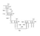
図2は、一般的な単結図の例を示す図である。
単結図において、符号101が母線設備、符号102が変圧器機器、符号103が送電線、符号104がLS(Line Switch)設備、符号105がCB(Circuit Breaker)設備(遮断器)である。各変電所・発電所では、このような単結図を用いてメンテナンスを行っている。
ここで、符号110のように母線から枝分かれしている線をブランチと称する。そして変圧器設備102や、LS設備104や、CB設備105などを機器と総称する。また、ブランチ110や、母線101や、機器を総称して、設備と称することとする。
<Example of single connection>
FIG. 2 is a diagram illustrating an example of a general single diagram.
In the single view,
Here, a line branching from the bus line as indicated by
《フローチャート》
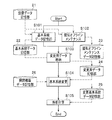
図3は、本実施形態に係る訓練用単結図の生成処理の手順を示すフローチャートである。
ユーザは、入力部30を介して、基本系統データ生成部11を起動すると、基本系統データ生成部11は、設備データ記憶部21の設備データを基に、基本系統データ生成画面(図示せず)を表示部40に表示する。ユーザは、基本系統データ生成画面をみながら、入力部30を介して、設備データから、後に行う解析計算に必要な情報を抽出する。基本系統データ生成部11は、設備データから抽出された情報を基本系統データとし、基本系統データ記憶部22に格納する基本系統データ生成を行う(S101)。なお、設備データには、電力系統に関する情報(母線の位置、接続情報、機器の抵抗値や、リアクタンスなど)のすべてが予め格納されている。
"flowchart"
FIG. 3 is a flowchart showing a procedure of processing for generating a training single figure according to the present embodiment.
When the user activates the basic system
また、ユーザが、擬似オフラインメンテナンス部12を起動し、擬似オフラインメンテナンス部12は、設備データ記憶部21の設備データを基に、後記する単結図画面および変更情報表示画面を表示部40に表示する。そして、ユーザが、表示されている単結図画面および変更情報表示画面をみながら、入力部30を介して擬似的なオフラインメンテナンス(擬似オフラインメンテナンス)を行う(S102)。ここで、擬似的なオフラインメンテナンスとは、一般的な訓練用システムにおけるオンラインメンテナンスと同様の手順で、オフラインメンテナンスも行うことである。
なお、擬似オフラインメンテナンスについては、後記して説明する。また、ステップS102の処理と、ステップS101の処理とは、どちらが先でもよい。
擬似オフラインメンテナンス部12は、擬似オフラインメンテナンスに関する情報を擬似オフラインメンテナンスデータとして、擬似オフラインメンテナンスデータ記憶部23に格納する。
Further, the user activates the
The pseudo off-line maintenance will be described later. In addition, either the process of step S102 or the process of step S101 may be performed first.
The pseudo
そして、変更用データ生成部13は、抽出された擬似オフラインメンテナンスデータと、基本系統データとを合せ、後の基本系統変更を行うための一時データである変更用データとする。そして、変更用データ生成部13は変更用データを変更用データ記憶部24に格納する(S103)。
Then, the change
次に、基本系統変更部14が、変更用データを基に、基本系統、すなわち訓練用の単結図の構成に対して、設備の縮約や、ダミー設備への置換といった変更(基本系統変更)を行う(S104)。基本系統の変更については、後記して説明する。
基本系統変更部14は、基本系統変更の結果を変更基本系統データとして変更基本系統データ記憶部25に格納する。このとき、基本系統変更部14が、開閉機器データ記憶部26の開閉機器データにおけるスイッチのオン・オフの情報を変更基本系統データに反映させてもよい。このような開閉機器データを反映させることで、後の解析計算において、スイッチがオフになっている設備の計算が省略可能となるため、解析計算の処理速度を向上させることができる。
Next, based on the change data, the basic
The basic
そして、ユーザが入力部30を介して訓練用のデータを入力すると、解析計算部15は、変更基本系統データと、入力された訓練用のデータを用いて電力の潮流計算などの訓練用の解析計算を行う(S105)。
When the user inputs training data via the
《擬似オフラインメンテナンス》
次に、図4を参照して、図3のステップS102における擬似オフラインメンテナンスの処理を説明する。
図4は、本実施形態に係る擬似オフラインメンテナンスの説明を行うための図である。
図4(a)は単結図表示画面例を示し、図4(b)は変更情報表示画面例を示す。
まず、ユーザは、図4(a)の単結図表示画面210において、縮約したい設備を選択する。単結図表示画面210に表示される単結図は、設備データを基に表示されるが、基本系統データを基に表示されてもよい。ここで、選択される設備は、母線や、ブランチなどである。図4(a)では、接続元設備としてブランチ211が選択され、接続先設備としてブランチ212が選択されることとする。なお、選択はマウスのクリックなどで行われる。また、ここでは、接続元設備と、接続先設備とを区別しているが、区別されていなくてもよい。
《Pseudo offline maintenance》
Next, the pseudo off-line maintenance process in step S102 of FIG. 3 will be described with reference to FIG.
FIG. 4 is a diagram for explaining the pseudo offline maintenance according to the present embodiment.
FIG. 4A shows an example of a single diagram display screen, and FIG. 4B shows an example of a change information display screen.
First, the user selects equipment to be contracted on the single diagram display screen 210 of FIG. The single diagram displayed on the single diagram display screen 210 is displayed based on the facility data, but may be displayed based on the basic system data. Here, the equipment to be selected is a bus or a branch. In FIG. 4A, the branch 211 is selected as the connection source equipment, and the
単結図表示画面210において、入力部30を介して、設備が選択されると、選択された設備の名称が、図4(b)に示す変更情報表示画面220に表示される。具体的には、選択された母線や、ブランチなどの設備の名称が変更情報表示画面の設備名称に表示される。図4(b)の例では「B12」、「B23」が選択された設備の名称に相当する。ここでは、上段の「B12」が接続元設備名称であり、下段の「B23」が接続先設備名称であるとするが、このような区別を行わなくてもよい。
When an equipment is selected via the
そして、ユーザは入力部30を介して選択された設備を変更した後の線路定数(抵抗値、リアクタンス、対地静電容量など)を入力する。入力された線路定数は、変更情報表示画面の線路定数表示欄に表示される。図4(b)の例では、縮約後の抵抗値(R)として「0.10」が入力され、リアクタンス(X)として「0.20」が入力され、対地静電容量(Y)として「0.30」が入力されている。
Then, the user inputs the line constant (resistance value, reactance, capacitance to ground, etc.) after changing the selected equipment via the
そして、変更した設備を、後の解析計算の対象とするか否かを示すフラグである計算フラグをユーザが入力部30を介して入力する。図4(b)の例では、有効ボタン221が選択されている場合は、計算フラグが「有効」であり、対象となるブランチが潮流計算の対象となることを示している。なお、計算フラグの入力は省略可能であるが、計算フラグを入力した場合、計算フラグが無効のブランチを解析計算の対象外とすることができ、その結果、解析計算の高速化を図ることができる。
And a user inputs the calculation flag which is a flag which shows whether the changed installation is made into the object of subsequent analysis calculation via the
このとき、擬似オフラインメンテナンス部23は、設備名称を基に、設備データを検索して、設備名称に対応する設備固有番号を取得すると、変更情報表示画面に表示されている設備名称(接続元、接続先)、設備固有番号(接続元、接続先)、線路定数、計算フラグの有効/無効の各情報を擬似オフラインメンテナンスデータ(設備の情報および属性情報)として擬似オフラインメンテナンスデータ記憶部23に格納する。
At this time, when the
これは、一般的な訓練用のシステムにおいて、オンラインメンテナンスに用いられている手法を利用したものである。 This uses a technique used for online maintenance in a general training system.
《基本系統変更》
次に、図5および図6を参照して、図3のステップS104における基本系統変更を説明する。
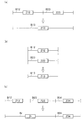
図5は、基本系統変更の例を示す図である。ここで、図5では、設備としてブランチが選択されている例を示す。
図5(a)は直列ブランチ合成(直列設備合成)の例を示す図である。
ここでは、ブランチB12およびブランチB23が1つのブランチB13に縮約され、機器Z12および機器Z23が1つの機器Z13に縮約されている。ここで、図4との対応を説明すると、ブランチB12およびブランチB23のそれぞれが図4(a)における接続元設備、接続先設備であり、機器Z13の線路定数が、図4(b)の線路定数(「R」、「X」、「Y」)に相当する。
《Basic system change》
Next, the basic system change in step S104 of FIG. 3 will be described with reference to FIGS.
FIG. 5 is a diagram illustrating an example of basic system change. Here, FIG. 5 shows an example in which a branch is selected as equipment.
FIG. 5A is a diagram illustrating an example of serial branch synthesis (serial facility synthesis).
Here, the branch B12 and the branch B23 are contracted to one branch B13, and the device Z12 and the device Z23 are contracted to one device Z13. Here, the correspondence with FIG. 4 will be described. Each of the branch B12 and the branch B23 is the connection source equipment and the connection destination equipment in FIG. It corresponds to a constant (“R”, “X”, “Y”).
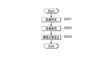
つまり、基本系統変更部14は、図6に示す以下の手順で基本系統変更を行う。
まず、基本系統変更部14は擬似オフラインメンテナンスデータを参照し、接続元設備および接続先設備の設備固有番号を取得すると、この設備固有番号を基に基本系統データにおいて対応する設備(ここではブランチ)を特定する(S201)。
次に、基本系統変更部14は、基本系統データにおいて接続元設備および接続先設備に該当する設備を1つに縮約する(S202)。
そして、基本系統変更部14は、擬似オフラインメンテナンスデータの線路定数を、縮約された設備における機器の線路定数として設定する(S203)。
That is, the basic
First, when the basic
Next, the basic
Then, the basic
図5(a)のような直列ブランチ合成は、2巻線変圧器などに適用される。例えば、2巻変圧器の1次、2次の2ブランチを直列接続することにより、1つのブランチ(設備)に縮約できる。 The series branch combination as shown in FIG. 5A is applied to a two-winding transformer or the like. For example, the primary and secondary branches of a two-winding transformer can be reduced to one branch (equipment) by connecting them in series.
図5(b)は並列ブランチ合成(並列設備合成)の例を示す図である。
ここでは、ブランチB12およびブランチB23が1つの母線B13に縮約され、機器Z12および機器Z23が1つの機器Z13に縮約されている。ここで、図4との対応を説明すると、母線B12および母線B23が図4(a)における接続元設備および接続先設備であり、機器Z13の線路定数が、図4(b)の線路定数(「R」、「X」、「Y」)に相当する。
FIG. 5B is a diagram illustrating an example of parallel branch synthesis (parallel facility synthesis).
Here, branch B12 and branch B23 are reduced to one bus B13, and device Z12 and device Z23 are reduced to one device Z13. Here, the correspondence with FIG. 4 will be described. The bus B12 and the bus B23 are the connection source equipment and the connection destination equipment in FIG. 4A, and the line constant of the device Z13 is the line constant ( "R", "X", "Y").
図5(b)のような並列ブランチ合成は、遮断器などの開閉機器がなく、同じ母線に接続されている2つの並列ブランチに適用される。例えば、開閉機器がなく、同じ母線に接続されている常時並列の2つのブランチは、常時並列であるため1つのブランチに縮約される。
なお、図5(b)に示す並列ブランチ合成の手順は、図6におけるステップS201〜S203の手順と同様であるため、手順の詳細な説明は省略する。
The parallel branch synthesis as shown in FIG. 5B is applied to two parallel branches connected to the same bus without a switching device such as a circuit breaker. For example, two always-parallel branches that have no switchgear and are connected to the same bus are always parallel and are reduced to one branch.
Note that the procedure of parallel branch synthesis shown in FIG. 5B is the same as the procedure of steps S201 to S203 in FIG.
図5(c)はダミーブランチ置換(ダミー設備置換)の例を示す図である。
ここでは、ブランチB12およびブランチB23が1つのダミーブランチBrに置換され、機器Z12および機器Z23が1つのダミー機器Zrに置換されている。なお、ブランチB34および機器Z34は変更されていない。図5(a)の直列ブランチ合成と異なる点は、直列ブランチ合成が2つのブランチを縮約しているのに対し、図5(c)では、まったく異なるダミーブランチで置換している点である。ここで、図4との対応を説明すると、母線B12および母線B23が図4(a)における接続元設備、接続先設備であり、設備Zrの線路定数が、図4(b)の線路定数(「R」、「X」、「Y」)に相当する。
FIG. 5C is a diagram showing an example of dummy branch replacement (dummy equipment replacement).
Here, the branch B12 and the branch B23 are replaced with one dummy branch Br, and the device Z12 and the device Z23 are replaced with one dummy device Zr. The branch B34 and the device Z34 are not changed. The difference from the serial branch composition of FIG. 5A is that the serial branch composition contracts two branches, whereas in FIG. 5C, a completely different dummy branch is substituted. . Here, the correspondence with FIG. 4 will be described. The bus B12 and the bus B23 are the connection source facility and the connection destination facility in FIG. 4A, and the line constant of the facility Zr is the line constant ( "R", "X", "Y").
例えば、図5(a)に示す直列ブランチ合成では、変更後の線路定数が変更前の各設備における線路定数の合成値などとなっているのに対し、図5(c)のダミーブランチ変換では、変更後の線路定数は変更前の各設備における線路定数とは関係のない値などが設定される。
なお、本実施形態では、直列ブランチをダミーブランチで置換しているが、並列ブランチをダミーブランチで置換してもよい。
For example, in the serial branch combination shown in FIG. 5A, the line constant after the change is a combined value of the line constant in each facility before the change, whereas in the dummy branch conversion of FIG. The line constant after the change is set to a value unrelated to the line constant in each facility before the change.
In this embodiment, the serial branch is replaced with a dummy branch, but the parallel branch may be replaced with a dummy branch.
なお、図5(c)に示すダミーブランチ追加の手順はステップS202やステップS203の「縮約」が「置換」となること以外は、図6におけるステップS201〜S203の手順と同様であるため、手順の詳細な説明は省略する。 The procedure for adding a dummy branch shown in FIG. 5C is the same as the procedure in steps S201 to S203 in FIG. 6 except that “contract” in step S202 or step S203 becomes “replacement”. Detailed description of the procedure is omitted.
《まとめ》
このような、基本系統変更を行うことにより、一般的な訓練用システムにおけるオンラインメンテナンスの方法を利用して、設備の構成を大きく変更する擬似オフラインメンテナンスを行った訓練用データを生成することができる。つまり、訓練用の電力系統にオフラインメンテナンスを行う際のユーザの負担を軽減することができる。
<Summary>
By performing such a basic system change, it is possible to generate training data that has been subjected to pseudo-offline maintenance that greatly changes the configuration of the equipment using an online maintenance method in a general training system. . That is, the burden on the user when performing offline maintenance on the power system for training can be reduced.
なお、ここでは、直列ブランチ合成(直列設備合成)、並列ブランチ合成(並列設備合成)、ダミーブランチ置換(ダミー設備置換)の3つについて記述したが、基本系統変更はこれに限らない。 Here, three branches, serial branch composition (serial equipment composition), parallel branch composition (parallel equipment composition), and dummy branch replacement (dummy equipment replacement) are described, but the basic system change is not limited to this.
本実施形態では、特許文献1に記載の技術では明記されていなかった、設備をまとめる手法が明らかになっている。また、本実施形態によれば、特許文献1のDC不要設備の省略に記載されているような複雑な処理を行わなくても、簡易な方法で単結図(基本系統)の変更を行うことが可能となる。 In the present embodiment, a technique for grouping facilities, which was not specified in the technique described in Patent Document 1, is clarified. In addition, according to the present embodiment, a simple diagram (basic system) can be changed by a simple method without performing complicated processing as described in Omission of DC unnecessary equipment in Patent Document 1. Is possible.
1 訓練用系統データ生成装置(電力系統モデル変更装置)
10 処理部
11 基本系統データ生成部
12 擬似オフラインメンテナンス部
13 変更用データ生成部
14 基本系統変更部(電力系統変更部)
15 解析計算部
21 設備データ記憶部
22 基本系統データ記憶部(電力系統モデルの情報を含む)
23 擬似オフラインメンテナンスデータ記憶部(設備の情報および属性情報を含む)
24 変更用データ記憶部
25 変更基本系統データ記憶部
26 開閉機器データ記憶部
30 入力部
40 表示部
1 System data generator for training (power system model change device)
DESCRIPTION OF SYMBOLS 10
15
23 Pseudo offline maintenance data storage (including equipment information and attribute information)
24 change
Claims (5)
前記電力系統モデル変更装置は、
入力部を介して、前記電力系統モデルにおいて変更対象となる複数の設備の情報および変更後における当該設備の属性情報が入力され、
前記変更対象となる複数の設備を、前記属性情報を有する1つの設備に置き換えることで、前記変更対象となる複数の設備を変更する
ことを特徴とする電力系統モデル変更方法。 A power system model changing method by a power system model changing device that changes the configuration of a power system model, which is a model of a power system having a plurality of facilities including busbars and branches,
The power system model changing device is:
Via the input unit, information of a plurality of facilities to be changed in the power system model and attribute information of the facilities after the change are input,
The power system model changing method, wherein the plurality of facilities to be changed are changed by replacing the plurality of facilities to be changed with one facility having the attribute information.
直列に接続されている複数の設備を、1つの設備に合成する直列設備合成、
並列に接続されている複数のブランチを、1つの設備に合成する並列設備合成、
および、複数のブランチを、1つのダミー設備で置換するダミー設備置換、
のいずれか1つである
ことを特徴とする請求項1に記載の電力系統モデル変更方法。 Changing a plurality of facilities to be changed is
Series equipment synthesis that synthesizes multiple equipment connected in series into one equipment,
Parallel facility synthesis that combines multiple branches connected in parallel into one facility,
And dummy equipment replacement to replace multiple branches with one dummy equipment,
It is any one of these. The electric power system model change method of Claim 1 characterized by the above-mentioned.
前記変更された電力系統モデルを基に、電力の解析計算を行う
ことを特徴とする請求項1または請求項2に記載の電力系統モデル変更方法。 The power system model changing device is:
The power system model changing method according to claim 1 or 2, wherein power calculation analysis is performed based on the changed power system model.
前記変更対象の設備を、解析計算の対象とするか否かのフラグである計算フラグが、前記変更された設備の情報に付与されている
ことを特徴とする請求項3に記載の電力系統モデル変更方法。 The power system model changing device is:
The electric power system model according to claim 3, wherein a calculation flag, which is a flag indicating whether or not the equipment to be changed is a target of analysis calculation, is added to the information on the changed equipment. Modification method.
入力部を介して、前記電力系統モデルにおいて変更対象となる複数の設備の情報および変更後における当該設備の属性情報が入力され、
前記変更対象となる複数の設備を、前記属性情報を有する1つの設備に置き換えることで、前記変更対象となる複数の設備を変更する電力系統変更部
を有することを特徴とする電力系統モデル変更装置。 A power system model changing device for changing the configuration of a power system model, which is a model of a power system having a plurality of facilities including busbars and branches,
Via the input unit, information of a plurality of facilities to be changed in the power system model and attribute information of the facilities after the change are input,
A power system model changing device comprising: a power system changing unit that changes the plurality of facilities to be changed by replacing the plurality of facilities to be changed with one facility having the attribute information. .
Priority Applications (1)
| Application Number | Priority Date | Filing Date | Title |
|---|---|---|---|
| JP2011124479A JP2012253902A (en) | 2011-06-02 | 2011-06-02 | Method and device for changing electric power system model |
Applications Claiming Priority (1)
| Application Number | Priority Date | Filing Date | Title |
|---|---|---|---|
| JP2011124479A JP2012253902A (en) | 2011-06-02 | 2011-06-02 | Method and device for changing electric power system model |
Publications (1)
| Publication Number | Publication Date |
|---|---|
| JP2012253902A true JP2012253902A (en) | 2012-12-20 |
Family
ID=47526161
Family Applications (1)
| Application Number | Title | Priority Date | Filing Date |
|---|---|---|---|
| JP2011124479A Pending JP2012253902A (en) | 2011-06-02 | 2011-06-02 | Method and device for changing electric power system model |
Country Status (1)
| Country | Link |
|---|---|
| JP (1) | JP2012253902A (en) |
Cited By (2)
| Publication number | Priority date | Publication date | Assignee | Title |
|---|---|---|---|---|
| JP2015012733A (en) * | 2013-06-28 | 2015-01-19 | 株式会社東芝 | System stabilization device |
| KR101743056B1 (en) * | 2015-12-15 | 2017-06-02 | 한전케이디엔주식회사 | Mapping apparatus for electric power facility |
Citations (4)
| Publication number | Priority date | Publication date | Assignee | Title |
|---|---|---|---|---|
| JPH1056735A (en) * | 1996-08-06 | 1998-02-24 | Chugoku Electric Power Co Inc:The | Power system model creation device |
| US6202041B1 (en) * | 1998-04-29 | 2001-03-13 | Hong Kong Polytechnic University | Electrical power network modelling method |
| JP2003032891A (en) * | 2001-07-13 | 2003-01-31 | Toshiba Corp | Data input support method and system for power system simulator, and data input support program |
| JP2004242452A (en) * | 2003-02-07 | 2004-08-26 | Mitsubishi Electric Corp | Power system reduced model generator |
-
2011
- 2011-06-02 JP JP2011124479A patent/JP2012253902A/en active Pending
Patent Citations (4)
| Publication number | Priority date | Publication date | Assignee | Title |
|---|---|---|---|---|
| JPH1056735A (en) * | 1996-08-06 | 1998-02-24 | Chugoku Electric Power Co Inc:The | Power system model creation device |
| US6202041B1 (en) * | 1998-04-29 | 2001-03-13 | Hong Kong Polytechnic University | Electrical power network modelling method |
| JP2003032891A (en) * | 2001-07-13 | 2003-01-31 | Toshiba Corp | Data input support method and system for power system simulator, and data input support program |
| JP2004242452A (en) * | 2003-02-07 | 2004-08-26 | Mitsubishi Electric Corp | Power system reduced model generator |
Non-Patent Citations (4)
| Title |
|---|
| JPN6014021623; 大坪昭: 「電気回路」 , 19771115, p.44-48, 電気書院 * |
| JPN6015004522; hanzaki: LTSPICE入門(連載4) LTSPICEを使ってみる(1) 回路図編集ツール , 20080324, エレキジャック * |
| JPN6015004523; hanzaki: LTSPICE入門(連載8) LTSPICEを使ってみる(5)電圧源の正弦波の設定方法 , 20080408, エレキジャック * |
| JPN6015048755; 棚木 義則 Yoshinori Tanagi: 'はじめてのPSpice PSpice/Captureインストール&操作マニュアル' トランジスタ技術 第39巻 第5号 Transistor Gijutsu 第39巻, 20020501, CQ出版株式会社 * |
Cited By (2)
| Publication number | Priority date | Publication date | Assignee | Title |
|---|---|---|---|---|
| JP2015012733A (en) * | 2013-06-28 | 2015-01-19 | 株式会社東芝 | System stabilization device |
| KR101743056B1 (en) * | 2015-12-15 | 2017-06-02 | 한전케이디엔주식회사 | Mapping apparatus for electric power facility |
Similar Documents
| Publication | Publication Date | Title |
|---|---|---|
| Lin et al. | A review of key strategies in realizing power system resilience | |
| Resener et al. | Optimization techniques applied to planning of electric power distribution systems: a bibliographic survey | |
| CN102967780B (en) | Modeling method for substation intelligent alarm | |
| Asija et al. | Power flow study and contingency status of WSCC 9 Bus test system using MATLAB | |
| CN112416344B (en) | Black start path generation and system recovery decision making system based on 3D visualization technology | |
| CN111478324B (en) | Power station alarm analysis system | |
| US20200273120A1 (en) | Power grid decision-making support device and method, and system applying same | |
| Sudhakar et al. | Restoration of power network–a bibliographic survey | |
| CN110569557A (en) | An intelligent independent design platform for power transmission and transformation engineering and its working method | |
| Chai et al. | Application of digital twin and hologram technology to achieve distribution network reliability forecast | |
| CN120300780A (en) | A power grid transformation and voltage regulation control system based on artificial intelligence | |
| Bai et al. | Automatic modeling and optimization for the digital twin of a regional multi-energy system | |
| CN106786597A (en) | The generation method and device of electric network fault correcting strategy | |
| JP2018119871A (en) | Accident prediction device, control method for the same, and program | |
| Snodgrass et al. | Case study of enhancing the matpower polish electric grid | |
| Xin | Insulation aging and fault diagnosis of high-voltage equipment based on deep Q-networks | |
| JP2012253902A (en) | Method and device for changing electric power system model | |
| Gérin-Lajoie et al. | Simulation of an extra large network in EMTP: From electromagnetic to electromechanical transients | |
| JP6960263B2 (en) | System operation support devices and methods in the power system, and wide area monitoring protection control system | |
| Xu et al. | Case-based reasoning for coordinated voltage control on distribution networks | |
| CN113489157A (en) | Power distribution network power supply state monitoring method, device, equipment and storage medium | |
| Ilić et al. | Physics-based foundations for cyber and market design in complex electric energy systems | |
| CN113131449B (en) | Setting method and device for protection device in distribution line | |
| UdayaSurian et al. | Distribution network reconfiguration during faults by path planning algorithm using minimum error current mapping technique | |
| CN104732101B (en) | The total active mistake load value of system determines method and system in Forming Electrical Dispatching Command Tickets |
Legal Events
| Date | Code | Title | Description |
|---|---|---|---|
| A621 | Written request for application examination |
Free format text: JAPANESE INTERMEDIATE CODE: A621 Effective date: 20130723 |
|
| A977 | Report on retrieval |
Free format text: JAPANESE INTERMEDIATE CODE: A971007 Effective date: 20140519 |
|
| A131 | Notification of reasons for refusal |
Free format text: JAPANESE INTERMEDIATE CODE: A131 Effective date: 20140603 |
|
| A521 | Written amendment |
Free format text: JAPANESE INTERMEDIATE CODE: A523 Effective date: 20140804 |
|
| A131 | Notification of reasons for refusal |
Free format text: JAPANESE INTERMEDIATE CODE: A131 Effective date: 20150210 |
|
| A521 | Written amendment |
Free format text: JAPANESE INTERMEDIATE CODE: A523 Effective date: 20150407 |
|
| A02 | Decision of refusal |
Free format text: JAPANESE INTERMEDIATE CODE: A02 Effective date: 20151208 |