JP2012255342A - Control device of engine - Google Patents
Control device of engine Download PDFInfo
- Publication number
- JP2012255342A JP2012255342A JP2011127272A JP2011127272A JP2012255342A JP 2012255342 A JP2012255342 A JP 2012255342A JP 2011127272 A JP2011127272 A JP 2011127272A JP 2011127272 A JP2011127272 A JP 2011127272A JP 2012255342 A JP2012255342 A JP 2012255342A
- Authority
- JP
- Japan
- Prior art keywords
- air amount
- predicted
- engine
- time
- amount
- Prior art date
- Legal status (The legal status is an assumption and is not a legal conclusion. Google has not performed a legal analysis and makes no representation as to the accuracy of the status listed.)
- Granted
Links
Images


Classifications
-
- F—MECHANICAL ENGINEERING; LIGHTING; HEATING; WEAPONS; BLASTING
- F02—COMBUSTION ENGINES; HOT-GAS OR COMBUSTION-PRODUCT ENGINE PLANTS
- F02D—CONTROLLING COMBUSTION ENGINES
- F02D41/00—Electrical control of supply of combustible mixture or its constituents
- F02D41/0002—Controlling intake air
-
- F—MECHANICAL ENGINEERING; LIGHTING; HEATING; WEAPONS; BLASTING
- F02—COMBUSTION ENGINES; HOT-GAS OR COMBUSTION-PRODUCT ENGINE PLANTS
- F02D—CONTROLLING COMBUSTION ENGINES
- F02D13/00—Controlling the engine output power by varying inlet or exhaust valve operating characteristics, e.g. timing
- F02D13/02—Controlling the engine output power by varying inlet or exhaust valve operating characteristics, e.g. timing during engine operation
- F02D13/0203—Variable control of intake and exhaust valves
- F02D13/0207—Variable control of intake and exhaust valves changing valve lift or valve lift and timing
-
- F—MECHANICAL ENGINEERING; LIGHTING; HEATING; WEAPONS; BLASTING
- F02—COMBUSTION ENGINES; HOT-GAS OR COMBUSTION-PRODUCT ENGINE PLANTS
- F02D—CONTROLLING COMBUSTION ENGINES
- F02D13/00—Controlling the engine output power by varying inlet or exhaust valve operating characteristics, e.g. timing
- F02D13/02—Controlling the engine output power by varying inlet or exhaust valve operating characteristics, e.g. timing during engine operation
- F02D13/0223—Variable control of the intake valves only
- F02D13/0234—Variable control of the intake valves only changing the valve timing only
- F02D13/0238—Variable control of the intake valves only changing the valve timing only by shifting the phase, i.e. the opening periods of the valves are constant
-
- F—MECHANICAL ENGINEERING; LIGHTING; HEATING; WEAPONS; BLASTING
- F02—COMBUSTION ENGINES; HOT-GAS OR COMBUSTION-PRODUCT ENGINE PLANTS
- F02D—CONTROLLING COMBUSTION ENGINES
- F02D41/00—Electrical control of supply of combustible mixture or its constituents
- F02D41/0002—Controlling intake air
- F02D2041/001—Controlling intake air for engines with variable valve actuation
-
- F—MECHANICAL ENGINEERING; LIGHTING; HEATING; WEAPONS; BLASTING
- F02—COMBUSTION ENGINES; HOT-GAS OR COMBUSTION-PRODUCT ENGINE PLANTS
- F02D—CONTROLLING COMBUSTION ENGINES
- F02D41/00—Electrical control of supply of combustible mixture or its constituents
- F02D41/02—Circuit arrangements for generating control signals
- F02D41/14—Introducing closed-loop corrections
- F02D41/1401—Introducing closed-loop corrections characterised by the control or regulation method
- F02D2041/1412—Introducing closed-loop corrections characterised by the control or regulation method using a predictive controller
-
- F—MECHANICAL ENGINEERING; LIGHTING; HEATING; WEAPONS; BLASTING
- F02—COMBUSTION ENGINES; HOT-GAS OR COMBUSTION-PRODUCT ENGINE PLANTS
- F02D—CONTROLLING COMBUSTION ENGINES
- F02D41/00—Electrical control of supply of combustible mixture or its constituents
- F02D41/02—Circuit arrangements for generating control signals
- F02D41/14—Introducing closed-loop corrections
- F02D41/1401—Introducing closed-loop corrections characterised by the control or regulation method
- F02D2041/1413—Controller structures or design
- F02D2041/1431—Controller structures or design the system including an input-output delay
-
- F—MECHANICAL ENGINEERING; LIGHTING; HEATING; WEAPONS; BLASTING
- F02—COMBUSTION ENGINES; HOT-GAS OR COMBUSTION-PRODUCT ENGINE PLANTS
- F02D—CONTROLLING COMBUSTION ENGINES
- F02D2200/00—Input parameters for engine control
- F02D2200/02—Input parameters for engine control the parameters being related to the engine
- F02D2200/04—Engine intake system parameters
- F02D2200/0402—Engine intake system parameters the parameter being determined by using a model of the engine intake or its components
-
- F—MECHANICAL ENGINEERING; LIGHTING; HEATING; WEAPONS; BLASTING
- F02—COMBUSTION ENGINES; HOT-GAS OR COMBUSTION-PRODUCT ENGINE PLANTS
- F02D—CONTROLLING COMBUSTION ENGINES
- F02D2200/00—Input parameters for engine control
- F02D2200/02—Input parameters for engine control the parameters being related to the engine
- F02D2200/04—Engine intake system parameters
- F02D2200/0411—Volumetric efficiency
-
- F—MECHANICAL ENGINEERING; LIGHTING; HEATING; WEAPONS; BLASTING
- F02—COMBUSTION ENGINES; HOT-GAS OR COMBUSTION-PRODUCT ENGINE PLANTS
- F02D—CONTROLLING COMBUSTION ENGINES
- F02D2250/00—Engine control related to specific problems or objectives
- F02D2250/12—Timing of calculation, i.e. specific timing aspects when calculation or updating of engine parameter is performed
-
- Y—GENERAL TAGGING OF NEW TECHNOLOGICAL DEVELOPMENTS; GENERAL TAGGING OF CROSS-SECTIONAL TECHNOLOGIES SPANNING OVER SEVERAL SECTIONS OF THE IPC; TECHNICAL SUBJECTS COVERED BY FORMER USPC CROSS-REFERENCE ART COLLECTIONS [XRACs] AND DIGESTS
- Y02—TECHNOLOGIES OR APPLICATIONS FOR MITIGATION OR ADAPTATION AGAINST CLIMATE CHANGE
- Y02T—CLIMATE CHANGE MITIGATION TECHNOLOGIES RELATED TO TRANSPORTATION
- Y02T10/00—Road transport of goods or passengers
- Y02T10/10—Internal combustion engine [ICE] based vehicles
- Y02T10/12—Improving ICE efficiencies
-
- Y—GENERAL TAGGING OF NEW TECHNOLOGICAL DEVELOPMENTS; GENERAL TAGGING OF CROSS-SECTIONAL TECHNOLOGIES SPANNING OVER SEVERAL SECTIONS OF THE IPC; TECHNICAL SUBJECTS COVERED BY FORMER USPC CROSS-REFERENCE ART COLLECTIONS [XRACs] AND DIGESTS
- Y02—TECHNOLOGIES OR APPLICATIONS FOR MITIGATION OR ADAPTATION AGAINST CLIMATE CHANGE
- Y02T—CLIMATE CHANGE MITIGATION TECHNOLOGIES RELATED TO TRANSPORTATION
- Y02T10/00—Road transport of goods or passengers
- Y02T10/10—Internal combustion engine [ICE] based vehicles
- Y02T10/40—Engine management systems
Landscapes
- Engineering & Computer Science (AREA)
- Chemical & Material Sciences (AREA)
- Combustion & Propulsion (AREA)
- Mechanical Engineering (AREA)
- General Engineering & Computer Science (AREA)
- Combined Controls Of Internal Combustion Engines (AREA)
- Electrical Control Of Ignition Timing (AREA)
- Control Of Throttle Valves Provided In The Intake System Or In The Exhaust System (AREA)
- Electrical Control Of Air Or Fuel Supplied To Internal-Combustion Engine (AREA)
Abstract
【課題】エンジンの制御装置に関し、シリンダに吸入される空気量を正確に予測してエンジンの制御性を向上させる。
【解決手段】エンジン10に要求される空気量を目標空気量として演算する目標空気量演算手段2bを備える。また、エンジン10のシリンダ19に吸入された実空気量を演算する実空気量演算手段2aを備える。さらに、目標空気量の演算時点から実空気量が目標空気量に達するまでの遅れに基づき、将来の実空気量の予測値を予測空気量として演算する予測手段3を備える。
【選択図】図1The present invention relates to an engine control device that accurately predicts the amount of air taken into a cylinder and improves the controllability of the engine.
SOLUTION: A target air amount calculating means 2b for calculating an air amount required for an engine 10 as a target air amount is provided. In addition, an actual air amount calculating means 2a for calculating the actual air amount sucked into the cylinder 19 of the engine 10 is provided. Furthermore, a predicting unit 3 is provided that calculates a predicted value of the future actual air amount as a predicted air amount based on a delay from when the target air amount is calculated until the actual air amount reaches the target air amount.
[Selection] Figure 1
Description
本発明は、シリンダに吸入される空気量を予測してエンジンを制御する制御装置に関する。 The present invention relates to a control device that controls an engine by predicting the amount of air taken into a cylinder.
一般的なエンジン制御では、エンジンに対する出力要求に応じて正確に燃料噴射量や吸入空気量,点火時期等を制御することが要求されている。燃料噴射量及び吸入空気量は空燃比に影響を与え、点火時期はシリンダ内での燃焼効率や安定性に影響を与える。したがって、これらの制御要素の演算精度は、エンジンの出力や排気性能を大きく左右する。
従来、この種のエンジン制御で用いられる演算手法として微分予測補正法が知られている。この微分予測補正法とは、シリンダに実際に吸入された空気量の過去の変化勾配を外挿して将来の吸気量を予測する演算手法である。
In general engine control, it is required to accurately control a fuel injection amount, an intake air amount, an ignition timing, and the like in accordance with an output request to the engine. The fuel injection amount and the intake air amount affect the air-fuel ratio, and the ignition timing affects the combustion efficiency and stability in the cylinder. Therefore, the calculation accuracy of these control elements greatly affects the output and exhaust performance of the engine.
Conventionally, a differential prediction correction method is known as a calculation method used in this type of engine control. This differential prediction correction method is a calculation method for predicting a future intake air amount by extrapolating a past change gradient of the air amount actually taken into the cylinder.
例えば、特許文献1には、吸気行程が終了する以前に燃料を噴射するエンジンの制御装置に関して、シリンダに吸入される空気量の予測値を演算し、その予測値に基づいて燃料噴射量を演算するものが記載されている。
この技術では、エンジンの一回転あたりの吸気量を周期的に検出するエアフローセンサーの検出値に基づいて最新の吸気量と前回の吸気量との差を演算し、この偏差に所定の予測ゲインを乗じたものを最新の吸気量に加算することによって将来の吸気量を予測している。このような手法を用いることで正確な吸気量の予測が可能となり、予測された吸気量で燃料噴射量を制御することで空燃比の変動やトルク変動を予防することができるとされている。
For example, in
In this technology, the difference between the latest intake air amount and the previous intake air amount is calculated based on the detected value of the air flow sensor that periodically detects the intake air amount per one rotation of the engine, and a predetermined predicted gain is added to this deviation. Future intake volume is predicted by adding the product to the latest intake volume. By using such a method, it is possible to accurately predict the intake air amount, and by controlling the fuel injection amount with the predicted intake air amount, it is said that air-fuel ratio fluctuations and torque fluctuations can be prevented.
しかしながら、上記のような予測手法では、吸気量の変化勾配が変動している状態のときに演算される予測値の精度が低下する場合がある。例えば、図4(a),(b)に実際の吸気量(実空気量)及び予測値の変動例をグラフ化して示す。ここでは、四ストローク四気筒エンジンで一行程毎に実空気量が演算され、実空気量が演算される行程よりも二行程前にその予測値が演算される例を示す。実空気量の予測値は、最新の実空気量と前回の実空気量との差を二倍した(予測ゲインが2である)ものとし、この予測値に基づいて燃料噴射量が設定されるものとする。 However, in the prediction method as described above, the accuracy of the predicted value calculated when the change gradient of the intake air amount is changing may be reduced. For example, FIGS. 4A and 4B are graphs showing examples of fluctuations in the actual intake air amount (actual air amount) and predicted values. Here, an example is shown in which the actual air amount is calculated for each stroke in a four-stroke four-cylinder engine, and the predicted value is calculated two strokes before the stroke in which the actual air amount is calculated. The predicted value of the actual air amount is obtained by doubling the difference between the latest actual air amount and the previous actual air amount (the prediction gain is 2), and the fuel injection amount is set based on this predicted value. Shall.
図4(a)は実空気量の変化勾配が一定の場合に対応し、図4(b)は実空気量の変化勾配が変化する場合に対応する。グラフの横軸は時間に対応し、ここではクランクシャフトの半回転(180[°CA])毎に縦線を引いて行程の区切りを示している。また、グラフの縦軸は空気量(実空気量やその予測値)を示す。なお、図中の太実線は実空気量を示し、破線はその予測値を示し、細実線は二行程後の実空気量を示す参照線である。 4A corresponds to the case where the change gradient of the actual air amount is constant, and FIG. 4B corresponds to the case where the change gradient of the actual air amount changes. The horizontal axis of the graph corresponds to time, and here, a vertical line is drawn for each half rotation of the crankshaft (180 [° CA]) to indicate a stroke delimiter. In addition, the vertical axis of the graph indicates the air amount (actual air amount and its predicted value). In the figure, the thick solid line indicates the actual air amount, the broken line indicates the predicted value, and the thin solid line is a reference line indicating the actual air amount after two strokes.
図中の時刻S0〜S2間では、実空気量が変動しないため、予測値は実空気量と同一値となる。時刻S2以降に実空気量が変化すると、その変化量に応じて予測値が演算される。このとき、実空気量の単位時間あたりの変化量が一定であれば、時刻S2〜S3間の増分が時刻S3〜S4間の増分と同一になり、これ以降も一定の割合で実空気量が増加する。したがって、時刻S2では、一行程あたりの実空気量の変化量を二倍した値が二行程先の実空気量にほぼ一致することになり、将来の実空気量を二行程前に予測することが可能となる。つまり、図4(a)に示すように、時刻S2以降では、破線グラフが細実線グラフに追従するように変化する。 Since the actual air amount does not fluctuate between the times S 0 to S 2 in the figure, the predicted value is the same value as the actual air amount. When the actual air quantity at a time S 2 and subsequent changes, the predicted value is calculated in accordance with the amount of change. At this time, if the amount of change per unit time of the actual air quantity is constant, increments between time S 2 to S 3 is the same as the increment between time S 3 to S 4, which later also at a constant rate The actual air volume increases. Thus, at time S 2, will be a value obtained by doubling the amount of change in the actual amount of air per stroke is substantially equal to the actual air amount of the secondary stroke destination predicting ago two lines the actual air quantity of the future It becomes possible. That is, as shown in FIG. 4 (a), the time S 2 and subsequent changes as a broken line graph follows the thin solid line.
一方、実空気量の単位時間あたりの変化量が一定でない場合には、図4(b)に示すように、予測値と二行程後の実空気量との間にずれが生じ、実空気量の予測精度が予測後の実空気量の変化勾配に左右される。例えば、実空気量の変化勾配が増大傾向にある時刻S2〜S3間では、吸気量がその後も増加するにも関わらず、時刻S2〜S3間の変化量を二倍した値が予測値として演算されるため、破線グラフが細実線グラフを下回り、予測値が二行程先の実空気量よりも小さくなる。時刻S0〜S3間の斜線部分は、空気量の予測値としての不足分に相当する。逆に、実空気量の変化勾配が減少傾向にある時刻S3以降では、破線グラフが細実線グラフを上回り、斜線部分で示される余剰分の空気量が予測値に含まれることとなる。 On the other hand, when the amount of change in the actual air amount per unit time is not constant, as shown in FIG. 4B, a deviation occurs between the predicted value and the actual air amount after the second stroke, and the actual air amount. The prediction accuracy depends on the change gradient of the actual air amount after the prediction. For example, between times S 2 and S 3 where the change gradient of the actual air amount tends to increase, a value obtained by doubling the amount of change between times S 2 and S 3 is obtained even though the intake air amount increases thereafter. Since the calculation is performed as the predicted value, the broken line graph is lower than the thin solid line graph, and the predicted value is smaller than the actual air amount ahead of the second stroke. The hatched portion between times S 0 to S 3 corresponds to a shortage as a predicted value of the air amount. Conversely, at the time S 3 after in the change gradient of the actual air quantity is decreasing, and the broken line graph exceeds a thin solid line, so that the air quantity of surplus represented by the shaded portion contained in the predicted value.
このように、シリンダに実際に吸入された空気量の過去の変化勾配に基づいて将来の吸気量を予測する従来の演算手法は予測エラーが大きく、吸気量の変化率が増加,減少しているような過渡状態では正確な予測が難しいという課題がある。このような予測精度の低下によって空燃比の変動やトルク変動が発生すると、エンジンの制御性が低下するおそれがある。 Thus, the conventional calculation method for predicting the future intake air amount based on the past change gradient of the air amount actually sucked into the cylinder has a large prediction error, and the change rate of the intake air amount is increased or decreased. In such a transient state, there is a problem that accurate prediction is difficult. If fluctuations in the air-fuel ratio and torque fluctuations occur due to such a decrease in prediction accuracy, the controllability of the engine may be reduced.
本件の目的の一つは、上記のような課題に鑑みて創案されたものであり、シリンダに吸入される空気量を正確に予測してエンジンの制御性を向上させることである。
なお、この目的に限らず、後述する発明を実施するための形態に示す各構成により導かれる作用効果であって、従来の技術によっては得られない作用効果を奏することも本件の他の目的として位置づけることができる。
One of the purposes of the present case was invented in view of the above problems, and is to accurately predict the amount of air taken into the cylinder and improve the controllability of the engine.
The present invention is not limited to this purpose, and is a function and effect derived from each configuration shown in the embodiments for carrying out the invention described later, and other effects of the present invention are to obtain a function and effect that cannot be obtained by conventional techniques. Can be positioned.
(1)ここで開示するエンジンの制御装置は、エンジンに要求される空気量を目標空気量として演算する目標空気量演算手段と、前記エンジンのシリンダに吸入された実空気量を演算する実空気量演算手段とを備える。また、前記目標空気量の演算時点から前記実空気量が該目標空気量に達するまでの遅れに基づき、将来の前記実空気量の予測値を予測空気量として演算する予測手段を備える。 (1) An engine control device disclosed herein includes target air amount calculating means for calculating an air amount required for the engine as a target air amount, and actual air for calculating the actual air amount sucked into the engine cylinder. A quantity calculating means. In addition, a predicting unit that calculates a predicted value of the future actual air amount as a predicted air amount based on a delay from when the target air amount is calculated until the actual air amount reaches the target air amount.
ここでいう「目標空気量の演算時点から実空気量が目標空気量に達するまで」とは、必ずしも目標空気量と実空気量とが一致するまでのことを意味するものではなく、実空気量の値が目標空気量の近傍に到達するまでといった意味合いを含む。また、ここでいう「遅れ」とは、目標空気量の演算時を基準時刻として、その目標空気量が実空気量に反映されるまでにかかる時間(例えば駆動遅れ時間)である。 Here, “from the time when the target air amount is calculated until the actual air amount reaches the target air amount” does not necessarily mean that the target air amount and the actual air amount coincide with each other. This means that the value of reaches the vicinity of the target air amount. Further, the “delay” here is a time (for example, drive delay time) required for the target air amount to be reflected in the actual air amount with reference to the calculation time of the target air amount.
(2)また、前記目標空気量の履歴を記憶する記憶手段を備え、前記予測手段が、前記目標空気量の履歴と前記実空気量とに基づいて前記予測空気量を演算することが好ましい。
(3)また、前記目標空気量に基づき、前記エンジンのスロットルバルブを制御する吸気制御手段を備え、前記記憶手段が、前記目標空気量の履歴として、少なくとも前記スロットルバルブの駆動遅れ時間に対応する所定時間分の過去の履歴を記憶することが好ましい。
(2) It is preferable that a storage unit that stores a history of the target air amount is provided, and the prediction unit calculates the predicted air amount based on the history of the target air amount and the actual air amount.
(3) In addition, intake control means for controlling the throttle valve of the engine based on the target air amount is provided, and the storage means corresponds to at least a drive delay time of the throttle valve as a history of the target air amount. It is preferable to store a past history for a predetermined time.
(4)また、前記予測手段が、予測時間幅演算手段,変化量演算手段及び予測空気量演算手段を有することが好ましい。前記予測時間幅演算手段は、前記予測値の演算時点から、前記実空気量が前記予測値になると推定される将来の時刻までの時間幅を演算するものである。また、前記変化量演算手段は、前記記憶手段に記憶された前記履歴のうち、前記予測値の演算時点よりも前記所定時間だけ過去の時点から前記時間幅が経過するまでの前記目標空気量の変化量を演算するものである。さらに、前記予測空気量演算手段は、前記実空気量と前記変化量とに基づいて、前記予測空気量を演算するものである。 (4) Moreover, it is preferable that the said prediction means has a prediction time width calculation means, a change amount calculation means, and a prediction air amount calculation means. The predicted time width calculation means calculates a time width from the time when the predicted value is calculated to a future time when the actual air amount is estimated to be the predicted value. In addition, the change amount calculation unit is configured to determine the target air amount of the history stored in the storage unit until the time width elapses from a point in time past the predetermined time from the calculation point of the predicted value. The amount of change is calculated. Further, the predicted air amount calculation means calculates the predicted air amount based on the actual air amount and the change amount.
(5)また、前記目標空気量演算手段での前記目標空気量の演算周期を検出する演算周期検出手段を備え、前記記憶手段が、前記演算周期を用いて換算された定周期相当の前記目標空気量の変化率の値を前記履歴として記憶することが好ましい。 (5) In addition, a calculation cycle detection unit that detects a calculation cycle of the target air amount in the target air amount calculation unit is provided, and the storage unit corresponds to the target corresponding to a fixed cycle converted using the calculation cycle. It is preferable to store the value of the change rate of the air amount as the history.
(6)また、前記予測空気量に基づき、前記エンジンの燃料噴射量を制御する燃料制御手段を備えることが好ましい。
(7)また、前記予測空気量に基づき、前記エンジンの点火時期を制御する点火制御手段を備えることが好ましい。
(6) Moreover, it is preferable to provide a fuel control means for controlling the fuel injection amount of the engine based on the predicted air amount.
(7) Moreover, it is preferable to provide an ignition control means for controlling the ignition timing of the engine based on the predicted air amount.
開示のエンジンの制御装置によれば、実空気量と目標空気量とを用いることで、実空気量の目標空気量に対する遅れの影響を考慮して予測空気量を正確に演算することができ、エンジンの制御性を向上させることができる。 According to the disclosed engine control device, by using the actual air amount and the target air amount, the predicted air amount can be accurately calculated in consideration of the influence of the delay of the actual air amount on the target air amount, The controllability of the engine can be improved.
図面を参照してエンジンの制御装置について説明する。なお、以下に示す実施形態はあくまでも例示に過ぎず、以下の実施形態で明示しない種々の変形や技術の適用を排除する意図はない。また、以下の実施形態の各構成は、必要に応じて取捨選択することができ、あるいは適宜組み合わせてもよく、実施形態の趣旨を逸脱しない範囲で種々変形して実施することができる。 An engine control apparatus will be described with reference to the drawings. Note that the embodiment described below is merely an example, and there is no intention to exclude various modifications and technical applications that are not explicitly described in the following embodiment. In addition, each configuration of the following embodiment can be selected as necessary, or may be appropriately combined, and various modifications can be made without departing from the spirit of the embodiment.
[1.装置構成]
[1−1.エンジン]
本実施形態のエンジンの制御装置は、車両に搭載された四気筒エンジン10に適用される。図1ではエンジン10に設けられた四つのシリンダ19(気筒)のうちの一つを示す。シリンダ19内を往復摺動するピストン16は、コネクティングロッドを介してクランクシャフト17に接続される。シリンダ19の燃焼室の頂部には、吸気ポート11及び排気ポート12が設けられるとともに、点火プラグ13がその先端を燃焼室側に突出させた状態で設けられる。
[1. Device configuration]
[1-1. engine]
The engine control apparatus of the present embodiment is applied to a four-
本エンジン10は、ピストン16がシリンダ19内を二往復する間に燃焼サイクルが一巡する四ストロークエンジンである。燃焼サイクルは、その進行順に、吸気行程,圧縮行程,燃焼行程,排気行程の四行程から構成される。一回の燃焼サイクルはクランクシャフト17の二回転(720[°CA])に相当し、各行程はクランクシャフト17の半回転(180[°CA])に相当する。
The
エンジン10の四つの気筒の燃焼サイクルは、クランクシャフト17の回転角について、互いに位相差を持つように設定されている。例えば、四つの気筒のそれぞれを#1気筒〜#4気筒とすると、#1気筒で吸気行程が開始されるときに、#2気筒で圧縮行程が開始されるとともに#4気筒で燃焼行程が開始され、同時に#3気筒で排気行程が開始されるように、180[°CA]毎の位相差が設定される。この場合、燃焼行程が実施される順序は、#1気筒,#3気筒,#4気筒,#2気筒の順となる。
The combustion cycles of the four cylinders of the
燃焼室のシリンダヘッド側の頂面には、吸気ポート11の入口を開閉する吸気弁14と、排気ポート12の入口を開閉する排気弁15とが設けられる。また、吸気ポート11内には、燃料を噴射するインジェクター18が設けられる。吸気弁14の開閉駆動により吸気ポート11と燃焼室とが連通又は閉鎖され、排気弁15の開閉駆動により排気ポート12と燃焼室とが連通又は遮断される。
An
吸気弁14及び排気弁15の上端部はそれぞれ、ロッカシャフトの一端に接続される。ロッカシャフトはロッカアームに軸支された揺動部材である。また、ロッカシャフトの他端には、カムシャフトに軸支されたカムが設けられる。これにより、ロッカシャフトの揺動パターンはカムの形状(カムプロファイル)に応じたものとなる。
The upper ends of the
[1−2.動弁系]
本エンジン10には、ロッカアーム31,33又はカム32,34の動作を制御する可変動弁機構9が設けられる。可変動弁機構9は、吸気弁14及び排気弁15のそれぞれについて、最大バルブリフト量及びバルブタイミングを個別に、又は、連動させつつ変更する機構である。可変動弁機構9は、ロッカアーム31,33の揺動量及び揺動のタイミングを変更するための機構として、バルブリフト量制御部9aとバルブタイミング制御部9bとを備える。
[1-2. Valve system]
The
バルブリフト量制御部9aは、吸気弁14や排気弁15の最大バルブリフト量を連続的に変更する機構である。このバルブリフト量制御部9aは、カム32,34からロッカアーム31,33に伝達される揺動の大きさを変更する機能を有する。ロッカアーム31,33の揺動の大きさを変更するための具体的な構造は任意である。
The valve lift
吸気弁14側を例に挙げると、カムシャフトに固定されたカム32とロッカアーム31との間に揺動部材を別途介装させ、この揺動部材を介してカムシャフトの回転運動をロッカアーム31の揺動運動に変換する構造とすることが考えられる。この場合、揺動部材の位置を移動させてカム32との接触位置を変更することで、揺動部材の揺動量が変化し、ロッカアーム31の揺動量も変化する。これにより、吸気弁14のバルブリフト量を連続的に変化させることが可能となる。なお、排気弁15側についても同様であり、カム34とロッカアーム33との間に揺動部材を介装する構造とすることで、排気弁15のバルブリフト量を調整可能となる。
Taking the
以下、ロッカシャフトに対する揺動部材の基準位置からの角度変化量のことを、制御角θVVLと呼ぶ。制御角θVVLはバルブリフト量に対応するパラメーターであり、制御角θVVLが大きいほどバルブリフト量が増大するように、揺動部材の基準位置が設定されている。バルブリフト量制御部9aは、この制御角θVVLを調節することによって、バルブリフト量を任意の値に制御する。
Hereinafter, the angle change amount from the reference position of the swinging member with respect to the rocker shaft is referred to as a control angle θ VVL . The control angle θ VVL is a parameter corresponding to the valve lift amount, and the reference position of the swing member is set so that the valve lift amount increases as the control angle θ VVL increases. The valve lift
バルブタイミング制御部9bは、吸気弁14や排気弁15の開閉のタイミング(バルブタイミング)を変更する機構である。このバルブタイミング制御部9bは、ロッカアーム31,33に揺動を生じさせるカム32,34又はカムシャフトの回転位相を変更する機能を有する。カム32,34又はカムシャフトの回転位相を変更することで、クランクシャフト17の回転位相に対するロッカアーム31,33の揺動のタイミングを連続的にずらすことが可能となる。
The valve timing control unit 9b is a mechanism that changes the opening / closing timing (valve timing) of the
以下、基準となるカムシャフトの位相角から実際のカムシャフトの位相角がどの程度進角又は遅角しているかを示す位相角の変化量のことを、位相角θVVTと呼ぶ。位相角θVVTは、バルブタイミングに対応するパラメーターである。バルブタイミング制御部9bは、この位相角θVVTを調整することによって、バルブタイミングを任意に制御する。 Hereinafter, a change amount of the phase angle indicating how much the actual camshaft phase angle is advanced or retarded from the reference camshaft phase angle is referred to as a phase angle θVVT . The phase angle θ VVT is a parameter corresponding to the valve timing. The valve timing control unit 9b arbitrarily controls the valve timing by adjusting the phase angle θ VVT .
[1−3.吸気系]
吸気ポート11内には、燃料を噴射するインジェクター18が設けられる。インジェクター18から噴射される燃料量は、後述するエンジン制御装置1によって電気的に制御される。また、インジェクター18よりも吸気流の上流側には、インテークマニホールド20(以下、インマニと呼ぶ)が設けられる。このインマニ20には、吸気ポート11側へと流れる空気を一時的に溜めるためのサージタンク21が設けられる。サージタンク21よりも下流側のインマニ20は、複数のシリンダ19に向かって分岐するように形成され、その分岐点にサージタンク21が位置する。サージタンク21は、各々のシリンダ19で発生する吸気脈動や吸気干渉を緩和するように機能する。
[1-3. Intake system]
An
インマニ20の上流端には、スロットルボディ23が接続される。スロットルボディ23の内部には電子制御式のスロットルバルブ24が内蔵され、インマニ20側へと流通する空気量がスロットルバルブ24の開度(スロットル開度θTH)に応じて調節される。このスロットル開度θTHは、エンジン制御装置1によって電子制御される。
A
スロットルボディ23の上流側には、吸気通路25が接続される。また、吸気通路25のさらに上流側にはエアフィルタ28が介装される。これにより、エアフィルタ28で濾過された新気が吸気通路25及びインマニ20を介してエンジン10のシリンダ19に供給される。
An
[1−4.検出系]
クランクシャフト17の一端には、その中心軸がクランクシャフト17の回転軸と一致するように設けられた円盤状のクランク板17aと、その回転角θCRを検出するクランク角センサー29が設けられる。回転角θCRの単位時間あたりの変化量は、エンジン10の実回転数Neに比例する。したがって、クランク角センサー29はエンジン10の実回転数Neを検出する機能を持つものといえる。ここで検出(または演算)された実回転数Neの情報は、エンジン制御装置1に伝達される。なお、クランク角センサー29で検出された回転角θCRに基づき、エンジン制御装置1で実回転数Neを演算する構成としてもよい。以下、エンジン10の実回転数Neのことを単にエンジン回転数Neとも呼ぶ。
[1-4. Detection system]
At one end of the
クランク板17a及びクランク角センサー29の具体的な形状や配置構成は任意である。クランクシャフト17の回転角θCRを把握するための典型的な手法としては、クランク板17aに形成された欠け歯を利用するものが挙げられる。例えば、図1に示すように、クランク板17aの外周面から放射方向に複数の歯部17bを形成し、それらの歯部17bの先端がクランク角センサー29の検出範囲内を通過するように配置する。
Specific shapes and arrangement configurations of the
ここで、複数の歯部17bの周方向の間隔を等間隔としたうえで、部分的に歯部17bを円周上の二箇所で欠落させて欠落部を設ける。これらの二箇所の欠落部の間隔はおよそ180[°CA]に設定する。また、クランク角センサー29は、歯部17bの先端を検知したときにオン信号を出力し、歯部17b間の隙間や欠落部が近接したときには信号出力を停止する(オフ信号を出力する)ポジションセンサとする。
このような構成の場合、クランクシャフト17が半回転する度にクランク角センサー29からオン信号が周期的に出力されることになる。周期的に出力されるオン信号は一般にSGT信号と呼ばれ、クランクシャフト17の回転数に対応する周波数のクロック信号として利用可能である。
Here, after the intervals in the circumferential direction of the plurality of
In such a configuration, an ON signal is periodically output from the
スロットルバルブ24の上流側及び下流側には、それぞれの位置での圧力を検出する大気圧センサー27及びインマニ圧センサー22が設けられる。大気圧センサー27はスロットルバルブ24の上流圧PB(大気圧)を検出するものであり、インマニ圧センサー22はスロットルバルブ24の下流圧PA(インマニ圧,サージタンク21内の圧力)を検出するものである。これらのインマニ圧センサー22及び大気圧センサー27で検出された下流圧PA及び上流圧PBの情報は、エンジン制御装置1に伝達される。
At the upstream side and the downstream side of the
車両の任意の位置には、アクセルペダルの踏み込み量に対応する操作量θACを検出するアクセルペダルセンサー30が設けられる。アクセルペダルの踏み込み操作量θACは、運転者の加速要求に対応するパラメーターであり、すなわちエンジン10への出力要求に対応する。ここで検出された操作量θACの情報は、エンジン制御装置1に伝達される。
An
[1−5.制御系]
この車両には電子制御装置として、エンジン制御装置1(Engine Electronic Control Unit)が設けられる。エンジン制御装置1は、例えばマイクロプロセッサやROM,RAM等を集積したLSIデバイスや組み込み電子デバイスとして構成され、車両に設けられたCAN,FlexRay等の通信ラインを介して他の電子制御装置や可変動弁機構9,各種センサー類と接続される。他の電子制御装置の具体例としては、図示しないCVT装置(変速装置)を制御するCVT-ECU35や空調装置を制御するエアコンECU36,電装品の動作を制御する電装品ECU37などが挙げられる。
[1-5. Control system]
This vehicle is provided with an engine control device 1 (Engine Electronic Control Unit) as an electronic control device. The
このエンジン制御装置1は、エンジン10に関する点火系,燃料系,吸排気系及び動弁系といった広汎なシステムを制御する電子制御装置である。ここでは、エンジン10に要求されるトルクの大きさを基準としたトルクベース制御が実施される。
エンジン制御装置1の具体的な制御対象としては、インジェクター18から噴射される燃料量や噴射時期,点火プラグ13での点火時期,吸気弁14及び排気弁15のバルブリフト量及びバルブタイミング,スロットルバルブ24の開度などが挙げられる。本実施形態では、エンジン10の目標空気量及び実空気量に基づいて数行程後の(将来の)実空気量を予測する予測制御に着目してその機能を説明する。
The
Specific control objects of the
[2.制御構成]
エンジン制御装置1の入力側にはエアフローセンサー26,インマニ圧センサー22,大気圧センサー27,クランク角センサー29及びアクセルペダルセンサー30が接続される。エンジン制御装置1は、これらのセンサーからの情報に基づき、エンジン10に要求されるトルクのうち、吸入空気量の調整によって達成されるトルク分の目標値を目標トルクとして算出する。また、エンジン制御装置1は、その目標トルクを発生させるのに必要な量の空気がシリンダ19に導入されるように、スロットルバルブ24のスロットル開度θTHを制御するとともに、予測される将来の実空気量に基づいてインジェクター18及び点火プラグ13を制御する。
[2. Control configuration]
An
図1に示すように、エンジン制御装置1には、演算部2,予測部3及び制御部4が設けられる。これらの演算部2,予測部3及び制御部4の各機能は、電子回路(ハードウェア)で実現してもよく、ソフトウェアとしてプログラミングされたものとしてよいし、あるいはこれらの機能のうちの一部をハードウェアとして設け、他部をソフトウェアとしたものであってもよい。
As shown in FIG. 1, the
[2−1.演算部]
演算部2は、予測制御に使用される各種パラメーターの演算を行うものである。ここには、実空気量演算部2a,目標空気量演算部2b,行程周期検出部2c,演算周期検出部2d,記憶部2eが設けられる。
[2-1. Calculation unit]
The
実空気量演算部2a(実空気量演算手段)は、エンジン10のシリンダ19に実際に吸入された空気量に対応する実充填効率Ecを演算するものである。ここでは、エアフローセンサー26で検出された吸気流量Qに基づいて実充填効率Ecが演算される。実充填効率Ecとは、一回の吸気行程(例えば、ピストン16が上死点から下死点に移動するまでの一行程)の間にシリンダ19内に充填される空気の体積を標準状態での気体体積に正規化したのちシリンダ容積で除算したものであり、その行程でシリンダ19内に新たに導入された空気量に対応するパラメーターである。
The actual air
実空気量演算部2aは、各シリンダ19での吸気行程が完了するタイミングで、周期的に実充填効率Ecを演算する。例えば、クランク角センサー29から伝達されるSGT信号の周期と同期するように、クランクシャフト17が半回転する毎に実充填効率Ecを演算する。ここで演算された実充填効率Ecの値は、予測部3に伝達される。
The actual air
目標空気量演算部2b(目標空気量演算手段)は、エンジン10に要求される空気量に対応する充填効率を目標充填効率EcTGTとして演算するものである。ここでは、エンジン10が出力すべき目標トルクの大きさが演算され、そのトルクを生じさせるのに必要な空気量が演算され、その空気量に対応する充填効率が目標充填効率EcTGTとして演算される。目標トルクは、エンジン回転数Ne,アクセルペダルの踏み込み操作量θACに応じて設定されるドライバ要求トルクのほか、CVT-ECU35,エアコンECU36,電装品ECU37などの動作に必要とされる外部要求トルク等に基づいて設定される。また、空気量及び目標充填効率EcTGTは、予め設定された目標トルクと目標充填効率EcTGTとの対応マップ,数式等に基づいて演算される。
The target air
目標充填効率EcTGTは、予め設定された演算周期TMAINで演算される。つまり、目標充填効率EcTGTは、エンジン10の燃焼サイクルに応じて演算される実充填効率Ecとは異なる間隔で演算される。なお、目標充填効率EcTGTの演算頻度は、エンジン10の運転状態に関わらず実充填効率Ecよりも高く設定されることが好ましい。例えば、目標充填効率EcTGTの演算周期TMAINを10[ms]〜12[ms]程度とすることが好ましい。ここで演算された目標充填効率EcTGTの値は、記憶部2e及び制御部4に伝達される。なお、制御部4では、目標充填効率EcTGTがスロットルバルブ24の開度制御や点火プラグ13の点火制御等に用いられる。
The target charging efficiency Ec TGT is calculated at a preset calculation cycle T MAIN . That is, the target charging efficiency Ec TGT is calculated at an interval different from the actual charging efficiency Ec calculated according to the combustion cycle of the
行程周期検出部2cは、クランク角センサー29から出力されるSGT信号に基づいてエンジン10の行程周期T180を演算するものである。この行程周期T180は、SGT信号がオンになる間隔に対応する時間である。ここで演算された行程周期T180の値は、予測部3に伝達される。
The stroke cycle detection unit 2 c calculates the stroke cycle T 180 of the
演算周期検出部2d(演算周期検出手段)は、目標空気量演算部2bでの目標充填効率EcTGTの演算周期TMAINを検出するものである。この演算周期TMAINは、上記の通り、基本的には予め設定された一定値(例えば10[ms])であるが、車両の運転状態やエンジン制御装置1の演算負荷などによって周期がやや延びる場合がある。そこで、演算周期検出部2dは、目標空気量演算部2bで目標充填効率EcTGTが演算されたときに、前回の目標充填効率EcTGTの演算時からの経過時間を計測し、これを演算周期TMAINとして記憶部2eに伝達する。
The
記憶部2e(記憶手段)は、目標空気量演算部2bで演算された目標充填効率EcTGTの履歴を記憶するものである。ここには、スロットルバルブ24の駆動遅れ時間に対応する所定時間分の過去の履歴が記憶される。駆動遅れ時間には、スロットルバルブ24がエンジン制御装置1からの制御信号を受けた時点から、実際にスロットルバルブ24の開度が制御信号の指示通りの状態に変化し終わるまでにかかる時間が含まれる。より正確には、目標空気量演算部2bで目標充填効率EcTGTが演算された時点を基準とし、その目標充填効率EcTGTがスロットルバルブ24の開度制御を経て実空気量演算部2aで演算される実充填効率Ecに反映されるまでにかかる時間に対応するパラメーターである。
The storage unit 2e (storage unit) stores the history of the target charging efficiency Ec TGT calculated by the target air
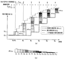
本実施形態では、スロットルバルブ24の駆動遅れ時間が60[ms]前後である場合を想定して、記憶部2eに過去60[ms]分の目標充填効率EcTGTの履歴を記憶させるものとする。例えば、図2(a)に示すように現在の時刻をt0として、前回の演算周期の時刻t10に演算されたものをEcTGT(n-1)とし、さらにその前回の時刻t20に演算されたものをEcTGT(n-2)として、六回前の演算周期の時刻t60に演算されたEcTGT(n-6)までの合計六個の過去のデータを記憶部2eに記憶させる。また、次回の演算周期に新たな目標充填効率EcTGTが演算されたときには、古いデータから順に破棄して常に直近の過去のデータを記憶部2eに記憶させる。
In the present embodiment, assuming that the drive delay time of the
あるいは、図2(b)に示すように、目標空気量演算部2bから新たな目標充填効率EcTGT(n)が入力される毎に、それまで記憶していた前回の目標充填効率EcTGT(n-1)との差dEcTGT10を演算して、記憶部2eに記憶させてもよい。この場合も、前回の演算周期で演算された値dEcTGT10をdEcTGT20に代入し、前回の演算周期で演算された値dEcTGT20をdEcTGT30に代入するといったように、過去60[ms]分の目標充填効率EcTGTの差dEcTGT10〜dEcTGT60の情報を随時更新しながら記憶させることが考えられる。
Alternatively, as shown in FIG. 2B, every time a new target charging efficiency Ec TGT (n) is input from the target air
なお、演算周期検出部2dで検出された演算周期TMAINを用いて、記憶部2eに記憶させる履歴情報を補正することとしてもよい。すなわち、目標空気量演算部2bから新たな目標充填効率EcTGTが入力されたときに、以下の式1に基づいて差dEcTGT10を演算することが考えられる。式1中のmax関数は、演算周期TMAIN [ms]又は10[ms]の何れか大きい一方の値を選択するものである。このような演算により、目標充填効率EcTGTの演算周期TMAINが10[ms]を超えた場合であっても、その目標充填効率EcTGTの変化量が10[ms]間の変化量(言い換えれば変化率)に換算されて記憶部2eに記憶される。
dEcTGT10={ EcTGT(n)− EcTGT(n-1)}×10 [ms]/max{TMAIN,10} [ms] …(式1)
The history information stored in the storage unit 2e may be corrected using the calculation cycle T MAIN detected by the calculation
dEc TGT10 = {Ec TGT (n) − Ec TGT (n-1) } × 10 [ms] / max {T MAIN , 10} [ms]… (Formula 1)
[2−2.予測部]
予測部3(予測手段)は、演算部2で演算された各種パラメーターを用いて、将来の実空気量の予測に係る各種演算を行うものである。ここには、予測時間幅演算部3a,変化量演算部3b及び予測空気量演算部3cが設けられる。
[2-2. Prediction unit]
The prediction unit 3 (prediction means) performs various calculations related to the prediction of the future actual air amount using the various parameters calculated by the
予測時間幅演算部3a(予測時間幅演算手段)は、現在の時刻から予測したい時刻までの時間幅Aを演算するものである。エンジン10の燃焼サイクルの各行程にかかる時間は、エンジン回転数Neに応じて変化する。そこで、予測時間幅演算部3aでは、行程周期検出部2cで検出された行程周期T180又はエンジン回転数Neに基づいて、時間幅Aを演算する。ここで演算された時間幅Aの値は、変化量演算部3bに伝達される。
The predicted time width calculator 3a (predicted time width calculator) calculates a time width A from the current time to the time to be predicted. The time required for each stroke of the combustion cycle of the
例えば、インジェクター18の燃料噴射量を制御する場合には、現時点から二行程先の予測したい将来の時刻までの時間幅Aが演算される。二行程分の時間は、クランクシャフト17が一回転するのに要する時間に等しく、以下の式2で与えられる。
A [ms]=2×T180 [ms](=60000 [rpm・ms]/ Ne [rpm]) …(式2)
For example, when the fuel injection amount of the
A [ms] = 2 × T 180 [ms] (= 60000 [rpm · ms] / Ne [rpm]) (Formula 2)
なお、上記の式2中の行程周期T180に乗じられる係数は、予測したい時刻までの行程数に一致する。つまり、予測したい時刻までの行程数が二行程でない場合(例えば、燃料噴射のタイミングが実充填効率Ecの演算時を基準として2.5行程前である場合や、1.5行程前である場合など)には、その行程数に応じて式2中の係数を適宜変更してもよい。
Note that the coefficient multiplied by the stroke period T 180 in the
変化量演算部3b(変化量演算手段)は、記憶部2eに記憶された過去の目標充填効率EcTGTに基づき、スロットルバルブ24の駆動遅れ時間に対応する60[ms]前の時点の目標充填効率EcTGTが、その時点から時間幅Aが経過するまでの間に変化した変化量ΔEcETMを演算するものである。例えば、予測時間幅演算部3aで演算された時間幅Aが40[ms]である場合には、60[ms]前を基点として40[ms]が経過する時点(20[ms]前の時点)までの目標充填効率EcTGTの変化量ΔEcETMを演算する。ここで演算された変化量ΔEcETMの値は、予測空気量演算部3cに伝達される。
Based on the past target charging efficiency Ec TGT stored in the storage unit 2e, the change
図2(a)に示すように、過去六回分の演算周期で得られた目標充填効率EcTGT(n-1)〜EcTGT(N-6)を記憶している場合には、例えば以下の表1のような関係を用いて変化量ΔEcETMを演算することが考えられる。 As shown in FIG. 2A, when the target charging efficiencies Ec TGT (n-1) to Ec TGT (N-6) obtained in the past six computation cycles are stored, for example, It is conceivable to calculate the change amount ΔEc ETM using the relationship shown in Table 1.

また、図2(b)に示すように、過去六回分の目標充填効率EcTGTの差dEcTGT10〜dEcTGT60を記憶している場合には、以下の表2のような関係を用いて変化量ΔEcETMを演算してもよい。 In addition, as shown in FIG. 2B, when the difference dEc TGT10 to dEc TGT60 of the target filling efficiency Ec TGT for the past six times is stored, the amount of change is calculated using the relationship shown in Table 2 below. ΔEc ETM may be calculated.
予測空気量演算部3c(予測空気量演算手段)は、実空気量演算部2aで演算された実充填効率Ecと、変化量演算部3bで演算された変化量ΔEcETMとに基づいて、実充填効率Ecの予測値を予測充填効率Ectbとして演算するものである。ここでは、実充填効率Ecが予め設定された所定の上限値EcMAX未満である場合に、以下の式3に従って予測充填効率Ectbが演算される。
Ectb=Ec+ΔEcETM …(式3)
The predicted air amount calculation unit 3c (predicted air amount calculation means) is based on the actual charging efficiency Ec calculated by the actual air
Ec tb = Ec + ΔEc ETM (Formula 3)
また、実充填効率Ecが上限値EcMAX以上である場合には、実充填効率EcにΔEcETMを加算することで予測充填効率Ectbが過度に大きくなる場合があるため、実充填効率Ecの値をそのまま予測充填効率Ectb(=Ec)に代入する演算を実施する。ここで演算された予測充填効率Ectbの値は制御部4に伝達される。
In addition, when the actual filling efficiency Ec is equal to or higher than the upper limit value Ec MAX , the predicted filling efficiency Ec tb may be excessively increased by adding ΔEc ETM to the actual filling efficiency Ec. An operation is performed in which the value is directly substituted for the predicted filling efficiency Ec tb (= Ec). Value of the predicted charging efficiency Ec tb computed here is transmitted to the
[2−3.制御部]
制御部4は、スロットルバルブ24やインジェクター18等の制御対象に伝達される具体的な制御信号を生成するものである。制御部4には、吸気制御部4a,燃料制御部4b及び点火制御部4cが設けられる。
[2-3. Control unit]
The
吸気制御部4a(吸気制御手段)は、目標空気量演算部2bで演算された目標充填効率EcTGTに基づいて吸入空気量を制御するものである。ここでは、シリンダ19内に実際に導入される空気量に対応する充填効率が目標充填効率EcTGTとなるように、スロットルバルブ24のスロットル開度θTHが制御される。スロットルバルブ24を通過する吸気量は、スロットル開度θTHと吸気の流速に応じたものとなる。また、吸気の流速は、スロットルバルブ24の上流圧PB及び下流圧PAやエンジン回転数Neなどに応じて演算される。そこで、吸気制御部4aは、目標充填効率EcTGTから算出される目標流量と吸気の流速、および吸気応答遅れ(吸気管容積による吸気遅れ)に応じて、スロットル開度θTHを制御する。
The
なお、吸気制御部4aでのスロットル開度θTHの制御時には、例えばエンジン10の運転状態や可変動弁機構9の制御角θVVL,位相角θVVT等が考慮され、これらが変化したとしても駆動遅れ時間がほぼ一定となる状態を維持するようにスロットルバルブ24が制御される。また、上記の予測部3での予測演算の前提となっている60[ms]前後の駆動遅れ時間には、この吸気制御部4aから制御信号が出力されてから実際にスロットルバルブ24の開度がスロットル開度θTHになるまでにかかる時間が含まれる。
When the throttle opening degree θ TH is controlled by the
燃料制御部4b(燃料制御手段)は、予測空気量演算部3cで演算された予測充填効率Ectbに基づいてシリンダ19毎の燃料噴射量を制御するものである。ここでは、インジェクター18から噴射される燃料量が予測充填効率Ectbに応じた量となるようにパルス幅の励磁信号が設定され、その励磁信号がインジェクター18に出力される。励磁信号のパルス幅は、例えば所望の空燃比と予測充填効率Ectbとに基づいて算出可能である。
この励磁信号の出力対象は、二行程後に吸気行程が終了するシリンダ19に設けられたインジェクター18である。また、インジェクター18に励磁信号が出力されるタイミングは、そのインジェクター18が設けられたシリンダ19の実充填効率Ecが演算される時点からおよそ二行程前である。このように、二行程後にシリンダ19内に吸入されるだろうと推定される空気量の予測値を踏まえて、燃料の噴射量が制御される。
The output target of this excitation signal is an
点火制御部4c(点火制御手段)は、実空気量演算部2aで演算された実充填効率Ecと、予測空気量演算部3cで演算された予測充填効率Ectbとに基づいて気筒毎の点火時期を制御するものである。ここでは、例えば実充填効率Ec又は予測充填効率Ectbで最大のトルクが発生する最適点火時期(MBT,Minimum spark advance for Best Torque)を基準としたリタード量がエンジン回転数Neに応じて設定され、設定されたリタード量となるタイミングで点火プラグ13に制御信号が出力される。
点火のタイミングは、そのシリンダ19への吸気が完了した時点よりも後である。つまり、点火制御が実施されるときには、すでに実充填効率Ecが演算されているため、必ずしも予測充填効率Ectbが要求されるわけではないが、実充填効率Ecが演算されるよりも前に演算された予測充填効率Ectbを用いることも可能である。
The timing of ignition is after the time when the intake to the
[4.作用]
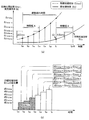
本制御装置による制御作用を説明する。図3(a)中の太実線グラフは実空気量演算部2aで演算される実充填効率Ecの変動を示し、一点鎖線グラフは目標空気量演算部2bで演算される目標充填効率EcTGTの変動を示し、細実線は二行程後の実充填効率を示す参照線である。また、グラフの横軸は時間に対応し、クランクシャフト17の半回転(180[°CA])毎に縦線を引いて行程の区切りを示している。グラフの縦軸は充填効率(実充填効率,目標充填効率,予測充填効率)を示す。
[4. Action]
The control action by this control apparatus will be described. The thick solid line graph in FIG. 3A shows the fluctuation of the actual charging efficiency Ec calculated by the actual air
実充填効率Ecは行程周期T180毎に演算され、目標充填効率EcTGTは演算周期TMAIN毎に演算されて、それぞれの値が随時更新される。図3(a)に示すように、エンジン回転数Neが1000[rpm]のときの行程周期T180は30[ms]であり、演算周期TMAINが10[ms]の場合には一行程の間に目標充填効率EcTGTの値が三回更新される。また、目標充填効率EcTGTが更新されると、その履歴がエンジン制御装置1の記憶部2eに記憶される。
Actual charging efficiency Ec is computed for each stroke cycle T 180, the target charging efficiency Ec TGT is calculated for each calculation cycle T MAIN, each value is updated from time to time. As shown in FIG. 3A, the stroke cycle T 180 when the engine speed Ne is 1000 [rpm] is 30 [ms], and when the calculation cycle T MAIN is 10 [ms] In the meantime , the target filling efficiency Ec TGT value is updated three times. When the target charging efficiency Ec TGT is updated, the history is stored in the storage unit 2e of the
時刻t0以前はエンジン10が定常運転の状態であり、実充填効率Ecが所定値Ec1で一定である。例えば時刻t0に加速要求が入力されると、その加速要求に応じて目標充填効率EcTGT(n)が目標空気量演算部2bで演算され、記憶部2e及び制御部4に伝達される。
Prior to time t 0, the
記憶部2eでは、新たな目標充填効率EcTGT(n)が入力される度に前回の値との差dEcTGTが演算され、順に記憶される。目標充填効率EcTGTが増大し始めた時刻B0以降の差dEcTGTの値は、図3(b)に示すように変動する。以下、時刻B0以降に記憶部2eに記憶される個々の差dEcTGTの大きさを古いものから順にZ1〜Z16と表記して説明する。 In the storage unit 2e, every time a new target charging efficiency Ec TGT (n) is input, a difference dEc TGT from the previous value is calculated and stored in order. The value of the difference dEc TGT after time B 0 when the target charging efficiency Ec TGT starts to increase fluctuates as shown in FIG. Hereinafter, the magnitudes of the individual differences dEc TGT stored in the storage unit 2e after time B 0 will be described in the order of oldest ones as Z 1 to Z 16 .
時刻B0の直後の時刻B1では、目標充填効率EcTGTの変動に対して実充填効率Ecの変動が追いついておらず、これより二行程先の時刻B3以降に実充填効率Ecが増大し始める。一方、時刻B1の時点で時刻B3に吸入されると予測される実充填効率の値が予測され、そのシリンダ19に関わる燃料噴射量,点火時期が制御される。
At time B 1 immediately after time B 0, the variation of the actual charging efficiency Ec for variations in target charging efficiency Ec TGT is not caught up, than this actual charging efficiency Ec is increased at time B 3 since the two-stroke destination Begin to. On the other hand, the value of the actual charging efficiency that is predicted to be sucked at time B 3 at time B 1 is predicted, and the fuel injection amount and ignition timing related to the
時刻B1の時点で予測充填効率Ectbの値を予測したい時刻はB3であり、予測時間幅演算部3aで演算される時間幅Aは60[ms]となる。したがって、変化量演算部3bでは過去六回分の目標充填効率EcTGTの差dEcTGTを加算した値が変化量ΔEcETMとして演算される。時刻B0よりも以前の差dEcTGTの値が0であるから、時刻B1の時点に変化量演算部3bで演算される変化量ΔEcETMの値はZ1となる。したがって、時刻B1に予測空気量演算部3cで演算される予測充填効率Ectbの値は所定値Ec1+Z1となる。
Time you want to predict the value of the predicted charging efficiency Ec tb at time B 1 represents a B 3, the time width A calculated by the prediction time width calculating unit 3a becomes 60 [ms]. Accordingly, the change
目標充填効率EcTGTは吸気制御部4aに伝達され、この値に基づいてスロットルバルブ24の開度が制御される。また、予測充填効率Ectbは燃料制御部4bに伝達され、この値に基づいてインジェクター18から噴射される燃料量が制御される。なお、ここで燃料が噴射されたシリンダ19は、二行程後の時刻B3前後に吸気行程が終了するシリンダ19である。
The target charging efficiency Ec TGT is transmitted to the
時刻B1から一行程分の時間(ここでは30[ms])が経過した時刻B2には、二行程先の時刻B4の実充填効率Ecが予測される。変化量演算部3bでは、時刻B2までの間に目標充填効率EcTGTの差dEcTGTが四回演算され、それぞれの値Z1〜Z4が記憶部2eに記憶されている。したがって、時刻B2に変化量演算部3bで演算される変化量ΔEcETMは、これらの値Z1〜Z4を加算した値となる。また、時刻B2の時点でもまだ実充填効率Ecの変化はないが、予測空気量演算部3cで演算される予測充填効率Ectbの値は所定値Ec1にZ1〜Z4を加算した値となる。
Time B 1 from a stroke amount of time to time B 2 has elapsed (here 30 [ms]) is, the actual charging efficiency Ec of the two stroke destination time B 4 are predicted. In the change
時刻B2からさらに一行程分の時間が経過した時刻B3には、時刻B5の実充填効率Ecが予測される。このとき記憶部2eに記憶されている目標充填効率EcTGTの差dEcTGTの値は、過去六回分のZ2〜Z7となる。したがって、時刻B3に変化量演算部3bで演算される変化量ΔEcETMは、Z2〜Z7を加算した値となる。
Time of one more stroke minutes from time B 2 is the time B 3 has elapsed, the actual charging efficiency Ec time B 5 is predicted. At this time, the value dEc TGT of the target charging efficiency Ec TGT stored in the storage unit 2e is Z 2 to Z 7 for the past six times. Thus, variation .DELTA.Ec ETM calculated by the change
また、時刻B3では、時刻B1における目標充填効率EcTGTの変動に対して実充填効率Ecの変動が追いつき、その値が所定値Ec2となる。したがって、予測空気量演算部3cで演算される予測充填効率Ectbの値は、所定値Ec2にZ2〜Z7を全て加算した値となる。 At time B 3 , the fluctuation of the actual charging efficiency Ec catches up with the fluctuation of the target charging efficiency Ec TGT at the time B 1 , and the value becomes the predetermined value Ec 2 . Therefore, the value of the predicted charging efficiency Ec tb calculated by the predicted air amount calculating unit 3c is a value obtained by adding all the Z 2 to Z 7 to a predetermined value Ec 2.
時刻B3以降も、一行程分の時間が経過する毎に実充填効率Ec及び予測充填効率Ectbが演算され、これらの値に基づいて吸気量及び燃料噴射量が制御される。このように、目標充填効率EcTGTに基づいて制御されるスロットルバルブ24の駆動遅れを利用して、目標充填効率EcTGTの変化量ΔEcETMをその時点の実充填効率Ecに加算することにより、予測充填効率Ectbの値と二行程後の実充填効率Ecの値とが一致する。
Time B 3 since even one actual charging efficiency Ec and predicted charging efficiency Ec tb whenever the stroke amount of time has elapsed are calculated, the intake air amount and the fuel injection amount on the basis of these values are controlled. Thus, by utilizing the driving lag of the
図3(a)に示すように、時刻B1,B2,…,B6の各々の時点で演算される予測充填効率Ectbの値は、細実線で示す二行程先の実充填効率Ecの挙動とほぼ一致したものとなり、すなわち60[ms]先の実充填効率Ecが正確に予測される。 As shown in FIG. 3 (a), the time B 1, B 2, ..., the value of the predicted charging efficiency Ec tb that is calculated at the time of each of B 6, the actual charging efficiency Ec of the two-stroke destination indicated by the thin solid line That is, the actual filling efficiency Ec 60 [ms] ahead is accurately predicted.
[5.効果]
上記の通り、本実施形態のエンジン制御装置1では、実充填効率Ecのみに基づく予測手法が用いられるのではなく、実充填効率Ecと目標充填効率EcTGTとを併用した予測手法が用いられる。これにより、実充填効率Ecの目標充填効率EcTGTに対する遅れの影響を考慮して予測充填効率Ectbを演算することができる。例えば、シリンダ19への吸気が完了するよりも以前に、そのシリンダ19に供給すべき燃料噴射量や点火時期を算出するための予測充填効率Ectbを正確に求めることが可能となり、エンジン10の制御性を向上させることができる。
[5. effect]
As described above, in the
例えば、エンジン制御装置1の燃料制御部4bでは、予測空気量演算部3cで予測された予測充填効率Ectbに基づいて燃料噴射量が制御されるため、吸気行程が完了する時点よりも以前に燃料噴射量を演算,制御することが可能となり、空燃比を正確に制御することが可能となる。特に、過渡時(実充填効率Ecの時間変化勾配が変動している時)の空燃比変動を抑制することができ、エンジントルクを正確に制御することができる。
For example, the engine control device 1 a
また、エンジン10の点火制御に関しても同様であり、予測充填効率Ectbに基づいて点火制御部4cで点火時期が制御されるため、吸気行程が完了する時点よりも以前にリタード量の目標値を演算することが可能となる。したがって、エンジン10の制御性をさらに高めることができる。なお、点火制御は吸気行程が完了した後に実施されるため、予測充填効率Ectb及び実充填効率Ecを併用してリタード量を演算することも可能である。このような演算手法を用いることで、エンジン10の制御性をさらに向上させることができる。
The same applies to the ignition control of the
また、上記のエンジン制御装置1では、目標充填効率EcTGTの履歴を用いて予測充填効率Ectbを演算している。これにより、目標充填効率EcTGTの過去の推移を踏まえて実充填効率Ecの今後の推移を予測することが可能となり、予測充填効率Ectbの予測精度を向上させることができる。したがって、エンジン10の制御性をより向上させることができる。
In the
また、上記のエンジン制御装置1の記憶部2eには、スロットルバルブ24の駆動遅れ時間に対応する所定時間分(例えば過去60[ms]分)の目標充填効率EcTGTの履歴が記憶されている。これにより、少なくとも所定時間が経過するまでの実充填効率Ecの推移を正確に把握することができ、エンジン10の制御性を向上させることができる。また、所定時間が経過する時点よりもさらに将来の予測充填効率Ectbに関しても予測が可能である。例えば、所定時間が経過する時点までの予測充填効率Ectbの変化傾向を外挿すればよい。
The storage unit 2e of the
また、上記のエンジン制御装置1では、予測したい将来の時刻までの時間幅で目標充填効率EcTGTの変化量ΔEcETMを求め、この変化量ΔEcETMと実充填効率Ecとを用いて将来の予測充填効率Ectbを演算している。これにより、目標充填効率EcTGTの値と駆動時間遅れ分だけ将来の実充填効率Ecの値とが一致していない場合であっても、実充填効率Ecの推移を正確に予測することができる。
Further, in the
なお、上記の式1に記載のように、演算周期検出部2dで検出された演算周期TMAINを用いて目標充填効率EcTGTの差dEcTGTを補正する構成とした場合には、目標充填効率EcTGTの演算周期TMAINが予め設定された10[ms]の周期よりも延びたとしても、補正された差dEcTGTの値は10[ms]間の変化率に換算されたものとなる。したがって、演算周期TMAINの増減の有無に関わらず、実充填効率Ecの予測のための変化量ΔEcETMの演算精度を維持することが可能となり、正確な予測充填効率Ectbの値を求めることができる。
In addition, as described in
[6.変形例]
上述の実施形態では、四気筒のエンジン10を制御するエンジン制御装置1を例示したが、上記の制御の適用対象はこれに限定されず、例えばストローク数や気筒数等は任意である。また、可変動弁機構9やCVT-ECU35等を持たないエンジン10であってもよい。
[6. Modified example]
In the above-described embodiment, the
また、上記のエンジン制御装置1では、目標充填効率EcTGTや実充填効率Ecをパラメーターとした予測演算を実施するものを示したが、少なくとも目標空気量に相当するパラメーターと実空気量に相当するパラメーターとが演算されるシステムであれば、上記のエンジン制御装置1を用いて予測充填効率Ectbを演算することが可能である。例えば、充填効率の代わりに、吸気通路25を通過する吸気流量や体積効率等を用いて同様の予測演算を実施してもよい。
Further, in the
また、上述の実施形態では、目標充填効率EcTGTの過去の推移を今後の実充填効率Ecの推移に対応させることで、実充填効率Ecの将来の予測値を求めるものを説明したが、目標充填効率EcTGTの推移と実充填効率Ecの推移との対応関係は必ずしも一定の関係に固定されているとは限らない。したがって、エンジン10の運転状態や環境条件に応じて変化量ΔEcETMを補正し、さらに正確な予測充填効率Ectbを演算することとしてもよい。
Further, in the above-described embodiment, the description has been given of obtaining the predicted value of the actual filling efficiency Ec by matching the past transition of the target filling efficiency Ec TGT with the future transition of the actual filling efficiency Ec. The correspondence relationship between the transition of the filling efficiency Ec TGT and the transition of the actual filling efficiency Ec is not necessarily fixed. Therefore, it is also possible to correct the variation .DELTA.Ec ETM in accordance with the operating conditions and environmental conditions of the
スロットルバルブ24の駆動応答性能が車両の走行条件に応じて変化し、これにより駆動応答遅れ時間が変化するような場合には、車両の走行条件に基づいて記憶部2eに記憶させる目標充填効率EcTGTの履歴データ数を増減させることが考えられる。
When the drive response performance of the
例えば、駆動応答遅れ時間が70[ms]前後である状態では、過去70[ms]分の目標充填効率EcTGTの履歴を記憶部2eに記憶させる。この場合、70[ms]前の時点から時間幅Aが経過するまでの間に変化した目標充填効率EcTGTの量を変化量ΔEcETMとすれば、上述の実施形態と同様に「現在の時刻における実充填効率Ec」に「駆動応答遅れ時間分の過去の時点から時間幅Aが経過するまでの間に変化した目標充填効率EcTGTの量(変化量ΔEcETM)」を加算することで予測充填効率Ectbを演算することが可能である。 For example, in a state where the drive response delay time is around 70 [ms], the history of the target filling efficiency Ec TGT for the past 70 [ms] is stored in the storage unit 2e. In this case, if the amount of the target charging efficiency Ec TGT that has changed from the time point 70 [ms] before the time width A elapses is assumed to be the change amount ΔEc ETM , “the current time” Predicted by adding "the amount of target filling efficiency Ec TGT that has changed from the past point in time corresponding to the drive response delay time to the elapse of time width A (change amount ΔEc ETM )" it is possible to calculate the charging efficiency Ec tb.
1 エンジン制御装置
2 演算部
2a 実空気量演算部(実空気量演算手段)
2b 目標空気量演算部(目標空気量演算手段)
2c 行程周期検出部
2d 演算周期検出部(演算周期検出手段)
2e 記憶部(記憶手段)
3 予測部(予測手段)
3a 予測時間幅演算部(予測時間幅演算手段)
3b 変化量演算部(変化量演算手段)
3c 予測空気量演算部(予測空気量演算手段)
4 制御部
4a 吸気制御部(吸気制御手段)
4b 燃料制御部(燃料制御手段)
4c 点火制御部(点火制御手段)
10 エンジン
Ec 実充填効率
EcTGT 目標充填効率
Ectb 予測充填効率
ΔEcETM 変化量
DESCRIPTION OF
2b Target air amount calculation unit (target air amount calculation means)
2c stroke
2e Storage unit (storage means)
3 Prediction unit (prediction means)
3a Prediction time width calculation unit (Prediction time width calculation means)
3b Change amount calculation unit (change amount calculation means)
3c Predicted air amount calculation unit (predicted air amount calculating means)
4
4b Fuel control unit (fuel control means)
4c Ignition control unit (ignition control means)
10 engine
Ec Actual filling efficiency
Ec TGT target filling efficiency
Ec tb Predicted filling efficiency ΔEc ETM change
Claims (7)
前記エンジンのシリンダに吸入された実空気量を演算する実空気量演算手段と、
前記目標空気量の演算時点から前記実空気量が該目標空気量に達するまでの遅れに基づき、将来の前記実空気量の予測値を予測空気量として演算する予測手段と、を備えた
ことを特徴とする、エンジンの制御装置。 Target air amount calculating means for calculating the air amount required for the engine as the target air amount;
An actual air amount calculating means for calculating an actual air amount sucked into the cylinder of the engine;
Prediction means for calculating a predicted value of the future actual air amount as a predicted air amount based on a delay from the time when the target air amount is calculated until the actual air amount reaches the target air amount. An engine control device.
前記予測手段が、前記目標空気量の履歴と前記実空気量とに基づいて前記予測空気量を演算する
ことを特徴とする、請求項1記載のエンジンの制御装置。 Storage means for storing a history of the target air amount;
2. The engine control apparatus according to claim 1, wherein the predicting unit calculates the predicted air amount based on a history of the target air amount and the actual air amount.
前記記憶手段が、前記目標空気量の履歴として、少なくとも前記スロットルバルブの駆動遅れ時間に対応する所定時間分の過去の履歴を記憶する
ことを特徴とする、請求項2記載のエンジンの制御装置。 Intake control means for controlling the throttle valve of the engine based on the target air amount,
3. The engine control apparatus according to claim 2, wherein the storage means stores a past history of a predetermined time corresponding to at least the throttle valve drive delay time as the target air amount history.
前記予測値の演算時点から、前記実空気量が前記予測値になると推定される将来の時刻までの時間幅を演算する予測時間幅演算手段と、
前記記憶手段に記憶された前記履歴のうち、前記予測値の演算時点よりも前記所定時間だけ過去の時点から前記時間幅が経過するまでの前記目標空気量の変化量を演算する変化量演算手段と、
前記実空気量と前記変化量とに基づいて、前記予測空気量を演算する予測空気量演算手段と、を有する
ことを特徴とする、請求項2又は3記載のエンジンの制御装置。 The prediction means is
Predicted time width calculating means for calculating a time width from the time of calculation of the predicted value to a future time when the actual air amount is estimated to be the predicted value;
Of the history stored in the storage means, a change amount calculation means for calculating a change amount of the target air amount until a time width elapses from a time point that is a predetermined time before the calculation time point of the predicted value. When,
The engine control apparatus according to claim 2, further comprising: a predicted air amount calculation unit that calculates the predicted air amount based on the actual air amount and the change amount.
前記記憶手段が、前記演算周期を用いて換算された定周期相当の前記目標空気量の変化率の値を前記履歴として記憶する
ことを特徴とする、請求項2〜4の何れか1項に記載のエンジンの制御装置。 Computation period detection means for detecting a calculation period of the target air amount in the target air amount calculation means,
5. The storage device according to claim 2, wherein the storage unit stores, as the history, a value of a change rate of the target air amount corresponding to a fixed cycle converted using the calculation cycle. The engine control device described.
ことを特徴とする、請求項1〜5の何れか1項に記載のエンジンの制御装置。 6. The engine control apparatus according to claim 1, further comprising a fuel control unit that controls a fuel injection amount of the engine based on the predicted air amount.
ことを特徴とする、請求項1〜6の何れか1項に記載のエンジンの制御装置。 The engine control device according to any one of claims 1 to 6, further comprising ignition control means for controlling an ignition timing of the engine based on the predicted air amount.
Priority Applications (4)
| Application Number | Priority Date | Filing Date | Title |
|---|---|---|---|
| JP2011127272A JP5594233B2 (en) | 2011-06-07 | 2011-06-07 | Engine control device |
| US13/417,361 US8909456B2 (en) | 2011-06-07 | 2012-03-12 | Engine control apparatus |
| EP12160042.3A EP2532866B1 (en) | 2011-06-07 | 2012-03-19 | Engine control apparatus |
| CN201210075027.8A CN102817728B (en) | 2011-06-07 | 2012-03-20 | Engine control equipment |
Applications Claiming Priority (1)
| Application Number | Priority Date | Filing Date | Title |
|---|---|---|---|
| JP2011127272A JP5594233B2 (en) | 2011-06-07 | 2011-06-07 | Engine control device |
Publications (2)
| Publication Number | Publication Date |
|---|---|
| JP2012255342A true JP2012255342A (en) | 2012-12-27 |
| JP5594233B2 JP5594233B2 (en) | 2014-09-24 |
Family
ID=45887983
Family Applications (1)
| Application Number | Title | Priority Date | Filing Date |
|---|---|---|---|
| JP2011127272A Active JP5594233B2 (en) | 2011-06-07 | 2011-06-07 | Engine control device |
Country Status (4)
| Country | Link |
|---|---|
| US (1) | US8909456B2 (en) |
| EP (1) | EP2532866B1 (en) |
| JP (1) | JP5594233B2 (en) |
| CN (1) | CN102817728B (en) |
Cited By (4)
| Publication number | Priority date | Publication date | Assignee | Title |
|---|---|---|---|---|
| WO2014142158A1 (en) * | 2013-03-12 | 2014-09-18 | ヤマハ発動機株式会社 | Vehicle control device and motorcycle |
| JP2017115777A (en) * | 2015-12-25 | 2017-06-29 | 三菱自動車工業株式会社 | Engine controller |
| JP2022019041A (en) * | 2020-07-17 | 2022-01-27 | 三菱電機株式会社 | Control device of internal combustion engine |
| JP7275416B1 (en) * | 2022-04-27 | 2023-05-17 | ヤマハ発動機株式会社 | Independent throttle 4-stroke engine |
Families Citing this family (1)
| Publication number | Priority date | Publication date | Assignee | Title |
|---|---|---|---|---|
| JP6147289B2 (en) * | 2015-04-08 | 2017-06-14 | 三菱電機株式会社 | Intake air volume estimation device for motorcycles |
Citations (7)
| Publication number | Priority date | Publication date | Assignee | Title |
|---|---|---|---|---|
| JPH07259621A (en) * | 1994-03-18 | 1995-10-09 | Mitsubishi Motors Corp | Fuel supply control device for internal combustion engine |
| JPH1182102A (en) * | 1997-09-04 | 1999-03-26 | Toyota Motor Corp | Control device for internal combustion engine |
| JP2000080952A (en) * | 1998-09-04 | 2000-03-21 | Nissan Motor Co Ltd | Engine intake air amount detection device |
| JP2001098998A (en) * | 1999-09-28 | 2001-04-10 | Toyota Motor Corp | Control device for internal combustion engine |
| JP2002039002A (en) * | 2000-07-25 | 2002-02-06 | Nissan Motor Co Ltd | Control device for supercharged engine |
| JP2002201998A (en) * | 2000-11-06 | 2002-07-19 | Denso Corp | Control device for internal combustion engine |
| JP2007332845A (en) * | 2006-06-14 | 2007-12-27 | Denso Corp | Control device for internal combustion engine |
Family Cites Families (17)
| Publication number | Priority date | Publication date | Assignee | Title |
|---|---|---|---|---|
| JPH0833117B2 (en) * | 1988-07-07 | 1996-03-29 | 三菱自動車工業株式会社 | Fuel injector |
| US6014955A (en) * | 1996-09-19 | 2000-01-18 | Toyota Jidosha Kabushiki Kaisha | Control apparatus for internal combustion engine using air-amount-first fuel-amount-second control method |
| JPH11159377A (en) * | 1997-12-01 | 1999-06-15 | Hitachi Ltd | Engine control device |
| JP2001263142A (en) * | 2000-03-15 | 2001-09-26 | Hitachi Ltd | Fuel injection device for internal combustion engine |
| JP3991619B2 (en) * | 2000-12-26 | 2007-10-17 | 日産自動車株式会社 | Air-fuel ratio control device for internal combustion engine |
| US6708102B2 (en) | 2002-08-01 | 2004-03-16 | Ford Global Technologies, Llc | Method and system for predicting cylinder air charge in an internal combustion engine for a future cylinder event |
| JP3900064B2 (en) * | 2002-10-30 | 2007-04-04 | トヨタ自動車株式会社 | Intake air amount estimation device for internal combustion engine |
| JP2004176638A (en) * | 2002-11-27 | 2004-06-24 | Toyota Motor Corp | Fuel injection amount control method for internal combustion engine and fuel injection amount control device |
| US7331317B2 (en) * | 2003-05-30 | 2008-02-19 | Honda Motor Co., Ltd. | Valve timing control system and control system for an internal combustion engine |
| US7107140B2 (en) * | 2004-10-08 | 2006-09-12 | Nissan Motor Co., Ltd. | Internal combustion engine control apparatus |
| JP4123214B2 (en) | 2004-10-08 | 2008-07-23 | 日産自動車株式会社 | Control device for internal combustion engine |
| US7275426B2 (en) | 2005-04-01 | 2007-10-02 | Wisconsin Alumni Research Foundation | Internal combustion engine control system |
| JP4828502B2 (en) * | 2006-11-29 | 2011-11-30 | 川崎重工業株式会社 | Internal combustion engine |
| JP4335249B2 (en) * | 2006-12-04 | 2009-09-30 | 三菱電機株式会社 | Control device for internal combustion engine |
| JP2008297946A (en) | 2007-05-30 | 2008-12-11 | Toyota Motor Corp | Control device for internal combustion engine |
| US8649959B2 (en) * | 2008-12-04 | 2014-02-11 | Toyota Jidosha Kabushiki Kaisha | Control device for internal combustion engine |
| DE112011104717B4 (en) * | 2011-01-14 | 2015-01-22 | Toyota Jidosha Kabushiki Kaisha | Control device for an internal combustion engine with a supercharger |
-
2011
- 2011-06-07 JP JP2011127272A patent/JP5594233B2/en active Active
-
2012
- 2012-03-12 US US13/417,361 patent/US8909456B2/en active Active
- 2012-03-19 EP EP12160042.3A patent/EP2532866B1/en active Active
- 2012-03-20 CN CN201210075027.8A patent/CN102817728B/en active Active
Patent Citations (7)
| Publication number | Priority date | Publication date | Assignee | Title |
|---|---|---|---|---|
| JPH07259621A (en) * | 1994-03-18 | 1995-10-09 | Mitsubishi Motors Corp | Fuel supply control device for internal combustion engine |
| JPH1182102A (en) * | 1997-09-04 | 1999-03-26 | Toyota Motor Corp | Control device for internal combustion engine |
| JP2000080952A (en) * | 1998-09-04 | 2000-03-21 | Nissan Motor Co Ltd | Engine intake air amount detection device |
| JP2001098998A (en) * | 1999-09-28 | 2001-04-10 | Toyota Motor Corp | Control device for internal combustion engine |
| JP2002039002A (en) * | 2000-07-25 | 2002-02-06 | Nissan Motor Co Ltd | Control device for supercharged engine |
| JP2002201998A (en) * | 2000-11-06 | 2002-07-19 | Denso Corp | Control device for internal combustion engine |
| JP2007332845A (en) * | 2006-06-14 | 2007-12-27 | Denso Corp | Control device for internal combustion engine |
Cited By (7)
| Publication number | Priority date | Publication date | Assignee | Title |
|---|---|---|---|---|
| WO2014142158A1 (en) * | 2013-03-12 | 2014-09-18 | ヤマハ発動機株式会社 | Vehicle control device and motorcycle |
| JP5997362B2 (en) * | 2013-03-12 | 2016-09-28 | ヤマハ発動機株式会社 | Vehicle control apparatus and motorcycle |
| JP2017115777A (en) * | 2015-12-25 | 2017-06-29 | 三菱自動車工業株式会社 | Engine controller |
| JP2022019041A (en) * | 2020-07-17 | 2022-01-27 | 三菱電機株式会社 | Control device of internal combustion engine |
| JP7275416B1 (en) * | 2022-04-27 | 2023-05-17 | ヤマハ発動機株式会社 | Independent throttle 4-stroke engine |
| WO2023209893A1 (en) * | 2022-04-27 | 2023-11-02 | ヤマハ発動機株式会社 | Independent-throttle-type four-stroke engine |
| TWI822628B (en) * | 2022-04-27 | 2023-11-11 | 日商山葉發動機股份有限公司 | Independent throttle four-stroke engine |
Also Published As
| Publication number | Publication date |
|---|---|
| EP2532866A2 (en) | 2012-12-12 |
| EP2532866B1 (en) | 2016-11-30 |
| US8909456B2 (en) | 2014-12-09 |
| US20120316758A1 (en) | 2012-12-13 |
| CN102817728A (en) | 2012-12-12 |
| JP5594233B2 (en) | 2014-09-24 |
| EP2532866A3 (en) | 2014-10-01 |
| CN102817728B (en) | 2016-01-06 |
Similar Documents
| Publication | Publication Date | Title |
|---|---|---|
| US7003390B2 (en) | Control device of internal combustion engine | |
| JP4740775B2 (en) | Engine intake air amount control device | |
| JP2012167636A (en) | Control device for engine | |
| US20110172898A1 (en) | Internal combustion engine system control device | |
| JP4207718B2 (en) | Control device for internal combustion engine | |
| JP5594233B2 (en) | Engine control device | |
| JP5944249B2 (en) | Internal EGR amount calculation device for internal combustion engine | |
| CN108431391A (en) | Method for the injection time started and emitted dose for determining fuel during the normal operating of internal combustion engine | |
| JP5994465B2 (en) | Engine control device | |
| JP5077562B2 (en) | Control device for internal combustion engine | |
| JP5598374B2 (en) | Engine control device | |
| JP5776530B2 (en) | Engine control device | |
| JP2012021434A (en) | Control apparatus of internal combustion engine | |
| JP3945509B2 (en) | Control device for internal combustion engine | |
| JP5002987B2 (en) | Engine cylinder intake gas amount measuring device | |
| JP4696617B2 (en) | Control device for multi-cylinder internal combustion engine | |
| JP4765703B2 (en) | Control device for variable valve mechanism | |
| JP4760604B2 (en) | Apparatus and method for estimating intake air amount of internal combustion engine | |
| JP6060812B2 (en) | Engine control device | |
| JP2010168953A (en) | Internal combustion engine injecting fuel in proportion to lift quantity of variable intake valve | |
| JP5861511B2 (en) | Engine control device | |
| JP2012188956A (en) | Engine control device | |
| JP2010285936A (en) | Control device for internal combustion engine | |
| JP3945510B2 (en) | In-cylinder charged air amount estimation device for internal combustion engine | |
| JP5998731B2 (en) | Engine control device |
Legal Events
| Date | Code | Title | Description |
|---|---|---|---|
| A621 | Written request for application examination |
Free format text: JAPANESE INTERMEDIATE CODE: A621 Effective date: 20130607 |
|
| A977 | Report on retrieval |
Free format text: JAPANESE INTERMEDIATE CODE: A971007 Effective date: 20131011 |
|
| A131 | Notification of reasons for refusal |
Free format text: JAPANESE INTERMEDIATE CODE: A131 Effective date: 20131022 |
|
| A521 | Written amendment |
Free format text: JAPANESE INTERMEDIATE CODE: A523 Effective date: 20131205 |
|
| TRDD | Decision of grant or rejection written | ||
| A01 | Written decision to grant a patent or to grant a registration (utility model) |
Free format text: JAPANESE INTERMEDIATE CODE: A01 Effective date: 20140708 |
|
| A61 | First payment of annual fees (during grant procedure) |
Free format text: JAPANESE INTERMEDIATE CODE: A61 Effective date: 20140721 |
|
| R151 | Written notification of patent or utility model registration |
Ref document number: 5594233 Country of ref document: JP Free format text: JAPANESE INTERMEDIATE CODE: R151 |
|
| S531 | Written request for registration of change of domicile |
Free format text: JAPANESE INTERMEDIATE CODE: R313531 |
|
| R350 | Written notification of registration of transfer |
Free format text: JAPANESE INTERMEDIATE CODE: R350 |