JP2012505809A - Method and transporting device for collecting empty items, especially bottles and cans - Google Patents
Method and transporting device for collecting empty items, especially bottles and cans Download PDFInfo
- Publication number
- JP2012505809A JP2012505809A JP2011535025A JP2011535025A JP2012505809A JP 2012505809 A JP2012505809 A JP 2012505809A JP 2011535025 A JP2011535025 A JP 2011535025A JP 2011535025 A JP2011535025 A JP 2011535025A JP 2012505809 A JP2012505809 A JP 2012505809A
- Authority
- JP
- Japan
- Prior art keywords
- empty
- transport device
- roller
- empty article
- article
- Prior art date
- Legal status (The legal status is an assumption and is not a legal conclusion. Google has not performed a legal analysis and makes no representation as to the accuracy of the status listed.)
- Granted
Links
Images


Classifications
-
- B—PERFORMING OPERATIONS; TRANSPORTING
- B07—SEPARATING SOLIDS FROM SOLIDS; SORTING
- B07C—POSTAL SORTING; SORTING INDIVIDUAL ARTICLES, OR BULK MATERIAL FIT TO BE SORTED PIECE-MEAL, e.g. BY PICKING
- B07C5/00—Sorting according to a characteristic or feature of the articles or material being sorted, e.g. by control effected by devices which detect or measure such characteristic or feature; Sorting by manually actuated devices, e.g. switches
- B07C5/04—Sorting according to size
- B07C5/12—Sorting according to size characterised by the application to particular articles, not otherwise provided for
- B07C5/122—Sorting according to size characterised by the application to particular articles, not otherwise provided for for bottles, ampoules, jars and other glassware
-
- B—PERFORMING OPERATIONS; TRANSPORTING
- B65—CONVEYING; PACKING; STORING; HANDLING THIN OR FILAMENTARY MATERIAL
- B65G—TRANSPORT OR STORAGE DEVICES, e.g. CONVEYORS FOR LOADING OR TIPPING, SHOP CONVEYOR SYSTEMS OR PNEUMATIC TUBE CONVEYORS
- B65G2201/00—Indexing codes relating to handling devices, e.g. conveyors, characterised by the type of product or load being conveyed or handled
- B65G2201/02—Articles
- B65G2201/0235—Containers
- B65G2201/0244—Bottles
-
- B—PERFORMING OPERATIONS; TRANSPORTING
- B65—CONVEYING; PACKING; STORING; HANDLING THIN OR FILAMENTARY MATERIAL
- B65G—TRANSPORT OR STORAGE DEVICES, e.g. CONVEYORS FOR LOADING OR TIPPING, SHOP CONVEYOR SYSTEMS OR PNEUMATIC TUBE CONVEYORS
- B65G47/00—Article or material-handling devices associated with conveyors; Methods employing such devices
- B65G47/02—Devices for feeding articles or materials to conveyors
- B65G47/04—Devices for feeding articles or materials to conveyors for feeding articles
- B65G47/12—Devices for feeding articles or materials to conveyors for feeding articles from disorderly-arranged article piles or from loose assemblages of articles
- B65G47/14—Devices for feeding articles or materials to conveyors for feeding articles from disorderly-arranged article piles or from loose assemblages of articles arranging or orientating the articles by mechanical or pneumatic means during feeding
- B65G47/1407—Devices for feeding articles or materials to conveyors for feeding articles from disorderly-arranged article piles or from loose assemblages of articles arranging or orientating the articles by mechanical or pneumatic means during feeding the articles being fed from a container, e.g. a bowl
- B65G47/1442—Devices for feeding articles or materials to conveyors for feeding articles from disorderly-arranged article piles or from loose assemblages of articles arranging or orientating the articles by mechanical or pneumatic means during feeding the articles being fed from a container, e.g. a bowl by means of movement of the bottom or a part of the wall of the container
- B65G47/1471—Movement in one direction, substantially outwards
-
- G—PHYSICS
- G07—CHECKING-DEVICES
- G07F—COIN-FREED OR LIKE APPARATUS
- G07F7/00—Mechanisms actuated by objects other than coins to free or to actuate vending, hiring, coin or paper currency dispensing or refunding apparatus
- G07F7/06—Mechanisms actuated by objects other than coins to free or to actuate vending, hiring, coin or paper currency dispensing or refunding apparatus by returnable containers, i.e. reverse vending systems in which a user is rewarded for returning a container that serves as a token of value, e.g. bottles
- G07F7/0609—Mechanisms actuated by objects other than coins to free or to actuate vending, hiring, coin or paper currency dispensing or refunding apparatus by returnable containers, i.e. reverse vending systems in which a user is rewarded for returning a container that serves as a token of value, e.g. bottles by fluid containers, e.g. bottles, cups, gas containers
Landscapes
- Engineering & Computer Science (AREA)
- Mechanical Engineering (AREA)
- Physics & Mathematics (AREA)
- General Physics & Mathematics (AREA)
- Control Of Conveyors (AREA)
- Sorting Of Articles (AREA)
- Attitude Control For Articles On Conveyors (AREA)
- Chain Conveyers (AREA)
- Feeding Of Articles To Conveyors (AREA)
- Vending Machines For Individual Products (AREA)
- Rollers For Roller Conveyors For Transfer (AREA)
Abstract
本発明は、大量投入により空物品特にびん及び缶を回収する方法であって、大量投入の際空物品(10)が、投入空間(8)から出て、運搬装置(1)によりその縦軸線の周りに回転しながら検出装置(14)のそばを通って導かれるものに関し、またこの方法を実施するため運搬方向に対して直角に設けられて互いに間隔を置く複数の連行体を持つ運搬装置に関する。このような方法及びこのような運搬装置において、高い処理能力が得られるようにする。これは、空物品(10)が運搬装置(1)により投入空間(8)から出て平行にされ、範囲配置の検出装置(14)へ供給されることによって、また連行体(4)が、少なくとも2個の空物品(10)を横に並んで受入れることができる幅に構成され、空物品(10)が少なくとも検出装置(14)の検出領域(15)で回転衝撃を受けることによって達せられる。The present invention is a method for recovering empty articles, particularly bottles and cans, by mass input, and in the case of mass input, empty articles (10) exit from the input space (8) and are conveyed by the conveying device (1) to the vertical axis thereof. Carrying apparatus having a plurality of entrainers spaced perpendicular to the carrying direction for carrying out the method, with respect to those guided by the detection device (14) while rotating around About. High throughput is obtained in such a method and in such a transport device. This is due to the empty article (10) being brought out of the input space (8) by the conveying device (1) and paralleled and fed to the detection device (14) in the range arrangement, and the entrainment (4) The width is configured to be able to receive at least two empty articles (10) side by side, and is achieved when the empty article (10) is subjected to a rotational impact at least in the detection region (15) of the detection device (14). .
Description
本発明は、請求項1及び2に記載の空物品特にびん及び缶を回収する方法及び運搬装置に関する。 The invention relates to a method and a transport device for recovering empty articles, in particular bottles and cans, according to
このような方法及び運搬装置は、自動空物品回収装置において使用される。この自動装置により、びん及び缶の形の使い捨て容器及び何回も使える容器を回収することができる。その際個別引込みシステムと大量引込みシステムとが区別される。 Such a method and conveying device is used in an automatic empty article collection device. With this automatic device, disposable containers in the form of bottles and cans and containers that can be used many times can be collected. In this case, a distinction is made between an individual withdrawal system and a mass withdrawal system.
個別引込みシステムを持つ自動空物品回収装置は、国際公開第02/12095号に開示されている。このような自動装置では、容器が手により連続して順次投入され、それから運搬装置により連続して即ち列をなして検出装置のそばを通され、検出装置により形状、状態、無傷、バーコード又は特別符号を検査される。 An automatic empty article collection device having an individual pull-in system is disclosed in WO 02/12095. In such an automatic device, the containers are successively inserted by hand and then continuously by the transport device, i.e. in a row, passed by the detection device, and by the detection device the shape, condition, intact, barcode or Special code is inspected.
大量引込みシステムを持つ自動空物品回収装置は、ドイツ連邦共和国の特許出願公開第102005025965号明細書、第102004010133号明細書及び第10335188号明細書に記載されている。この自動装置では、回収すべき空物品は、個々に即ち1個ずつ投入されるのではなく、大量に即ちいわばばら荷として投入される。投入は投入空間へ行われ、投入空間から空物品が運搬装置により搬出される。従来技術による自動装置では、投入空間から出て、空物品が連続的にばらばらにされ、それからこの配置で個別引込みシステムにおけるのと同じように、運搬装置により検出装置のそばを通され、この検出装置により空物品が順番に個々に検出される。 Automatic empty article collection devices with a mass pull-in system are described in German patent applications 102005025965, 102004010133 and 10335188. In this automatic apparatus, the empty articles to be collected are not supplied individually, that is, one by one, but are supplied in large quantities, that is, as bulk goods. Input is performed to the input space, and empty articles are carried out of the input space by the transport device. In the automatic device according to the prior art, the empty articles are continuously separated out of the input space, and then in this arrangement are passed by the detection device by the conveying device as in the individual retracting system. The apparatus detects empty articles individually in order.
上述した大量引込みシステムは、自動装置への空物品の投入が利用者のために急速に問題なく行われる、という利点を持っている。しかしその欠点は、連続的にばらばらにするため、自動装置による処理は、空物品の部分的に高い個別運搬速度にもかかわらず、多くの時間を要するので、顧客は比較的長時間保証受領の表出を待たねばならない。 The mass pull-in system described above has the advantage that empty articles can be loaded into an automatic device quickly and without problems for the user. However, the disadvantage is that it breaks down continuously, so that processing by automated equipment takes a lot of time despite the partially high individual transport speeds of empty articles, so customers can receive a warranty for a relatively long time. I have to wait for the expression.
従って本発明の課題は、空物品特にびん及び缶の回収のための方法及び運搬装置を、高い処理能力で利用可能にすることである。 The object of the present invention is therefore to make available a method and a transport device for the recovery of empty articles, in particular bottles and cans, with high throughput.
この課題は、本発明によれば請求項1に記載の方法及び2に記載の運搬装置によって解決される。 This problem is solved according to the invention by the method according to claim 1 and the transport device according to
本発明によれば、投入空間からの空物品の搬出は平行にされて行われ、それにより空物品は範囲配置で検出装置へ供給される。範囲配置とは、運搬装置にある空物品が搬送方向に見て順番に上下に又は前後に配置されているだけでなく、同時に横に並んで配置されていることも意味する。この方法を実現するため、運搬装置の連行体が、少なくとも2個の空物品を横に並んで受入れることができる幅に構成され、空物品が少なくとも検出装置の検出領域で回転衝撃を受けるので、空物品は同時に並進搬送されながらその縦軸線の周りに回転する。縦軸線の周りの回転運動は、個別引込みシステムにおけるように、空物品の周面に存在する標識等を検出装置により検出できるようにするために必要である。この手段により、自動回収装置による空物品の処理能力が著しく高められる。 According to the present invention, empty articles are carried out from the input space in parallel, whereby empty articles are supplied to the detection device in a range arrangement. Range arrangement means not only that the empty articles in the transporting device are arranged in order in the conveyance direction, but are arranged side by side at the same time. In order to realize this method, the entrainment body of the transport device is configured to have a width that can receive at least two empty articles side by side, and the empty article receives a rotational impact at least in the detection region of the detection apparatus. The empty article rotates around its longitudinal axis while being simultaneously translated. Rotational motion about the longitudinal axis is necessary to enable the detection device to detect signs or the like present on the peripheral surface of the empty article, as in an individual retraction system. By this means, the processing capacity of the empty article by the automatic recovery apparatus is remarkably enhanced.
本発明の第1の有利な実施形態では、運搬装置が空物品用の当接面を持っている。この当接面の周りに線状辺特に鎖辺が循環し、互いに間隔をおいて設けられるローラがこの鎖辺に回転可能に支持されて、空物品用連行体として機能する。ローラ上にある空物品の回転駆動は、当接面を持ちかつこの当接面に対して並進運動せしめられるローラの摩擦係合により簡単に行うことができ、それによりローラが回転し、回転衝撃を空物品へ伝達する。基礎が両側にラック状範囲を持ち、ローラにかみ合う歯車がこれらのラック状範囲にかみ合うことによって、ローラと基礎とのはまり合いによりローラを回転駆動することも考えられる。 In a first advantageous embodiment of the invention, the conveying device has an abutment surface for empty articles. A linear side, particularly a chain side, circulates around the contact surface, and rollers provided at intervals are rotatably supported by the chain side to function as an empty article entrainment body. The rotational driving of the empty article on the roller can be easily performed by the frictional engagement of the roller having a contact surface and being translated with respect to the contact surface. To the empty article. It is also conceivable that the foundation has a rack-like area on both sides, and a gear meshing with the roller meshes with these rack-like areas, so that the roller is rotationally driven by the fit between the roller and the foundation.
本発明の別の実施形態では、ローラが当接面から両側へ突出し、これらの突出範囲で回転駆動のため、当接面に関し駆動鎖の互いに反対の側に設けられているレールに、摩擦係合又ははまり合いで当接している。それによりローラの回転方向従って空物品の回転方向も、前述した構成に対して逆にされ、その結果検出装置の検出領域の高さが有利に減少する。この実施形態では、検出装置の検出領域の高さのそれ以上の減少は、両方の突出範囲におけるローラ(はまり合いの場合歯車)の直径が、ローラの連行体範囲おけるより小さいことによって実現され、ここで連行体範囲とは、空物品が載っているローラの範囲を意味する。この手段により、空物品の周速が高められる。 In another embodiment of the present invention, the roller protrudes from the abutting surface to both sides, and in order to drive the rotation within these protruding ranges, a frictional engagement is applied to rails provided on opposite sides of the drive chain with respect to the abutting surface. They are in contact with each other. As a result, the direction of rotation of the roller, and hence the direction of rotation of the empty article, is also reversed with respect to the configuration described above, with the result that the height of the detection area of the detection device is advantageously reduced. In this embodiment, a further reduction in the height of the detection area of the detection device is realized by the fact that the diameter of the rollers (gears in the case of mating) in both protruding ranges is smaller in the roller entrainment range, Here, the entrained body range means a range of the roller on which the empty article is placed. By this means, the peripheral speed of the empty article is increased.
上述した実施形態に対し、次のようにすることによっても検出装置の検出領域を短くすることができる。即ちローラが当接面から両側へ突出し、これらの突出範囲で回転駆動のため、駆動鎖に関し当接面の側に設けられているレールに、摩擦係合又ははまり合いで当接し、突出範囲におけるローラ(はまり合いの場合歯車)の直径が、ローラの連行体範囲おけるより小さい。この構成では、空物品は第1の実施形態におけるのと同じ回転方向を持つが、もっと大きい周速を持っている。 The detection area of the detection device can be shortened by performing the following as compared with the above-described embodiment. That is, the roller protrudes from the contact surface to both sides, and is driven to rotate in these protrusion ranges, so that it contacts the rail provided on the contact surface side with respect to the drive chain with frictional engagement or interference, and in the protrusion range. The diameter of the roller (gear in the case of mating) is smaller than the roller entrainment range. In this configuration, the empty article has the same rotational direction as in the first embodiment, but has a higher peripheral speed.
ローラが交互に小さい直径の部分及び大きい直径の部分から成り、空物品が大きい直径の部分に載っていると、有利なことがわかった。その場合空物品の連行は障害なく行われ、特にローラのこの構成では、空物品がローラと当接面との間に食い込むことがない。 It has been found to be advantageous if the roller consists of alternating small diameter and large diameter parts and the empty article rests on the large diameter part. In that case, the empty article is carried without any obstacle, and in this configuration of the roller in particular, the empty article does not bite between the roller and the contact surface.
本発明の別の実施形態では、空物品用当接面に、連行体上にある空物品の回転駆動用駆動ローラ又は駆動ベルトがはめられていることによって、空物品の回転駆動を行うことができる。この場合連行体は例えば桟片として構成することができる。 In another embodiment of the present invention, an empty article is driven to rotate by being fitted with a driving roller or drive belt for rotating the empty article on the entrained body on the contact surface for the empty article. it can. In this case, the entrainment body can be configured as a crosspiece, for example.
本発明の別の構成では、運搬装置が、特に60°〜85°の傾斜角を持つ急傾斜コンベアとして構成されている。それにより自動回収装置の全体深さが小さくされる。他方この急傾斜範囲では、連行体上に複数個の空物品が重なって運搬されるのを防止されることがわかった。なぜならば、余分な個数の空物品は投入空間へ戻るからである。 In another configuration of the invention, the conveying device is configured as a steeply inclined conveyor having an inclination angle of 60 ° to 85 ° in particular. This reduces the overall depth of the automatic recovery device. On the other hand, it has been found that in this steep slope range, it is possible to prevent a plurality of empty articles from being overlapped and transported on the entrainment body. This is because an extra number of empty articles returns to the input space.
本発明が実施例により以下に説明される。 The invention is explained below by means of examples.
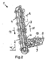
概略的な図面は、他の部分を示してない自動空物品回収装置の急傾斜コンベア1を示す。この実施例では、急傾斜コンベア1の傾斜角αは60°〜85°の範囲にある。急傾斜コンベア1は、その両方の縦辺に循環する駆動鎖2,3を持ち搬送方向に対して直角に設けられるローラ4がこれらの駆動鎖に回転可能に支持されている。ローラ4は、等間隔で周囲に分布して駆動鎖2及び3に支持され、交互の部分5及び6は小さい直径及び大きい直径を持っている。ローラ4は、少なくとも駆動鎖2及び3の上辺で、剛性の定置当接面7上を移動し、それにより摩擦係合により回転駆動される。 The schematic drawing shows a steeply inclined conveyor 1 of an automatic empty article collection device that does not show other parts. In this embodiment, the inclination angle α of the steeply inclined conveyor 1 is in the range of 60 ° to 85 °. The steeply inclined conveyor 1 has drive
急傾斜コンベアの傾斜角αは最大90°であってもよい。この場合ローラ4は、搬送すべき空物品10の最大直径より大きい直径を持たねばならない。 The maximum inclination angle α of the steep conveyor may be 90 °. In this case, the
急傾斜コンベア1の下端に、上方へ開くホッパ状投入空間8が設けられている。投入空間8の底9は、急傾斜コンベア1の方へ下方へ傾斜している。投入空間8へ、缶及びびんの形の空物品10が、ぶちあげにより例えばポケットからばら荷として投入される。底9の傾斜のため駆動力が存在して、空物品10を急傾斜コンベア1の方へ転がらせるか又は滑らせる。急傾斜コンベア1のローラ4は投入空間8を通過し、それによる空物品10が、ローラ4の直径の大きい方の部分6上に載って連行される。ローラ4は、図1からわかるように、少なくとも2個の空物品10がローラ4上に載ることができるような幅である。 A hopper-
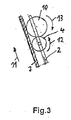
急傾斜コンベア1は空物品10を投入空間8から上方へ搬送する。搬送方向は図2及び3に矢印11で示されている。ローラ4が当接面7上で転がるので、ローラ4は図3に矢印12で示すように反時計方向に回転駆動される。それによりローラ4にある空物品10は、図3に矢印13で示すように時計方向に駆動される。この回転方向のため、空物品10は当接面7へ押付けられるので、それがローラ4から滑り落ちることはない。急傾斜コンベア1の上端で空物品10は、自動回収装置の図示してない次の装置へ引渡される。 The steeply inclined conveyor 1 conveys the
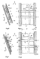
急傾斜コンベア1は、投入空間8及びローラ4を除いて図4に示されるように、検出装置に属するカメラ14にそばを通って空物品を導く。カメラ14は広がった検出領域15を持っている。この検出領域15は急傾斜コンベア1の全幅を持ち、検出領域15の高さHは、それが最大直径を持つ空物品10の少なくとも転がる周面に等しいように選ばれている。それにより1個の空物品10の周面にあるすべての標識、バーコード又はその他の特徴を確実に検出することがえきる。カメラは、適当な機能照明付きで特定の角をなして急傾斜コンベアの上方に特定の間隔をおいて設けられ、それにより回転する空物品10の上方運搬中に、その周囲にある標識等を光電的に実時間で検出することができる。更にカメラ装置によって、全装置を監視し、その撮影を適切なサービス手段のために利用することができる。 As shown in FIG. 4, except for the
図5及び6には本発明の第2実施例が示されている。これらの図において、同じ部材に対して第1実施例の符号が引継がれる。急傾斜コンベア1は、その原理的構造において第1実施例のそれに一致している。従って急傾斜コンベアは、空物品10用の装置剛性当接面7、投入空間8及び連行体として機能するローラ4を持ち、これらのローラ4は当接面7の周りに循環する駆動鎖2,3に回転可能に支持されている。第1実施例におけるようにローラ4は当接面上を転がらず、両側へ当接面7から突出し、それにより形成される突

図7及び8には本発明の別の実施例が示されている。前述した第2実施例とは異なり、ここではレール16が、駆動鎖2及び3に関して、当接面7の側に設けられている。ロー
Claims (12)
Applications Claiming Priority (3)
| Application Number | Priority Date | Filing Date | Title |
|---|---|---|---|
| DE102008052330A DE102008052330A1 (en) | 2008-10-20 | 2008-10-20 | Method and transport device for taking back empties, in particular bottles and cans |
| DE102008052330.5 | 2008-10-20 | ||
| PCT/EP2009/007507 WO2010046085A1 (en) | 2008-10-20 | 2009-10-20 | Method and conveyor device for returning empties, in particular bottles and cans |
Publications (2)
| Publication Number | Publication Date |
|---|---|
| JP2012505809A true JP2012505809A (en) | 2012-03-08 |
| JP5833445B2 JP5833445B2 (en) | 2015-12-16 |
Family
ID=41508390
Family Applications (1)
| Application Number | Title | Priority Date | Filing Date |
|---|---|---|---|
| JP2011535025A Active JP5833445B2 (en) | 2008-10-20 | 2009-10-20 | Method and transporting device for collecting empty items, especially bottles and cans |
Country Status (9)
| Country | Link |
|---|---|
| US (1) | US9010519B2 (en) |
| EP (1) | EP2353149B1 (en) |
| JP (1) | JP5833445B2 (en) |
| CN (1) | CN102349094B (en) |
| AU (1) | AU2009306699B2 (en) |
| CA (1) | CA2741056C (en) |
| DE (1) | DE102008052330A1 (en) |
| DK (1) | DK2353149T3 (en) |
| WO (1) | WO2010046085A1 (en) |
Families Citing this family (17)
| Publication number | Priority date | Publication date | Assignee | Title |
|---|---|---|---|---|
| DE102008052330A1 (en) | 2008-10-20 | 2010-06-17 | Envipco Holding N.V. | Method and transport device for taking back empties, in particular bottles and cans |
| DE102009017211B3 (en) * | 2009-04-09 | 2010-11-18 | Envipco Holding N.V. | Device for taking back empties, in particular plastic bottles and metal cans |
| DE102010037274A1 (en) * | 2010-09-02 | 2012-03-08 | Wincor Nixdorf International Gmbh | Empty bottle acceptance method used in reverse vending machine, involves sorting the empty bottles based on the bottle characteristic determined by bottle characteristic recognition unit |
| DE102010048840A1 (en) * | 2010-10-18 | 2012-04-19 | Envipco Holding N.V. | Device for taking back empties, in particular plastic bottles and metal cans |
| DE102011015239B3 (en) | 2011-03-26 | 2012-06-06 | Envipco Holding N.V. | Method and transport device for taking back empties |
| CN104029982B (en) * | 2013-03-05 | 2016-11-02 | 常州江润精密机械有限公司 | The automatic detection production line of bottle |
| CN103922110B (en) * | 2014-04-17 | 2016-03-23 | 石家庄开发区冀科双实科技有限公司 | The Bottle arrangement machine structure of medicinal glass bottle manufacturing line |
| EP3152137A4 (en) * | 2014-06-06 | 2017-11-22 | Gebo Cermex Canada Inc. | Device and method for intervening on a conveyor line |
| US9382025B2 (en) * | 2014-06-30 | 2016-07-05 | Marel Meat Processing Inc. | Conveying system for transporting, transferring and staging food products |
| EP2996092A1 (en) * | 2014-09-09 | 2016-03-16 | Envipco Holding N.V. | Device for collecting empty containers |
| US9729832B2 (en) | 2014-11-14 | 2017-08-08 | Envipco Holding N.V. | Device for measuring the length and diameter of a container using structured lighting, and method of use |
| WO2017111978A1 (en) * | 2015-12-23 | 2017-06-29 | Fives Intralogistics Corp. | Stepped wall singulator conveyor for oversized item removal |
| EP3452536B1 (en) * | 2016-05-04 | 2024-01-17 | Basf Se | Self-cooling foam-containing composite materials |
| KR102055052B1 (en) * | 2018-02-27 | 2019-12-11 | 주식회사 에버스톤 | Apparatus for injecting dough to make ice cream |
| CN108273762A (en) * | 2018-03-26 | 2018-07-13 | 天津中德应用技术大学 | Rotary type product image harvester and application method |
| CN108535276A (en) * | 2018-06-20 | 2018-09-14 | 建湖国创机械制造有限公司 | A kind of Bottle detection stage apparatus of intelligence image checking machine |
| CN112722490B (en) * | 2021-01-09 | 2022-07-15 | 杭州本浩科技有限公司 | Feeding device of packaging machine |
Citations (11)
| Publication number | Priority date | Publication date | Assignee | Title |
|---|---|---|---|---|
| JPS5337649U (en) * | 1976-09-04 | 1978-04-03 | ||
| JPS5341247U (en) * | 1976-09-16 | 1978-04-10 | ||
| JPS59227611A (en) * | 1983-06-10 | 1984-12-20 | 東急車輌製造株式会社 | Selector for empty can of recovery car for empty can |
| JPH02100906A (en) * | 1988-10-08 | 1990-04-12 | Sato Noki Kk | Feeder for carrots and the like |
| JPH03100217U (en) * | 1990-02-01 | 1991-10-21 | ||
| JPH04130227U (en) * | 1991-05-20 | 1992-11-30 | 有限会社武藤選果機製作所 | Agricultural product sorting equipment |
| JPH0731937A (en) * | 1993-07-19 | 1995-02-03 | Techno Frontier:Kk | Bottle automatic flat-layer sorting device |
| JPH0721504U (en) * | 1993-05-14 | 1995-04-18 | 株式会社南部電機製作所 | Egg orientation device |
| JP2000105202A (en) * | 1998-09-29 | 2000-04-11 | Minolta Co Ltd | Inspecting device for pinhole in cylindrical container |
| JP2002338026A (en) * | 2001-05-16 | 2002-11-27 | Sekisui House Ltd | Support structure for the intermediate part of the roller chain conveyor |
| JP2004059093A (en) * | 2002-07-30 | 2004-02-26 | Nikka Densoku Kk | Inspection system |
Family Cites Families (41)
| Publication number | Priority date | Publication date | Assignee | Title |
|---|---|---|---|---|
| US2702112A (en) * | 1952-04-15 | 1955-02-15 | Fmc Corp | Fruit inspecting means |
| GB981328A (en) * | 1960-05-21 | 1965-01-20 | Erik Harry Laurentius Olofsson | A method and apparatus for receiving returnable containers |
| US3300021A (en) * | 1963-08-29 | 1967-01-24 | Fmc Corp | Method and apparatus for handling articles |
| US3282394A (en) * | 1963-08-30 | 1966-11-01 | Abc Packaging Machine Corp | Bottle orienting machine |
| US3331486A (en) * | 1966-04-27 | 1967-07-18 | Giorgio Corp Di | Bottle handling apparatus |
| US3580380A (en) * | 1968-09-11 | 1971-05-25 | Reynolds Metals Co | Method of and apparatus for orienting indicia bearing cylindrical objects |
| US3598222A (en) * | 1969-04-03 | 1971-08-10 | Int Machinery Corp Sa | High-speed feed mechanism |
| US3624773A (en) * | 1970-06-17 | 1971-11-30 | Pace Packaging Corp | Continuously moving apparatus for uprighting bottles |
| US3715024A (en) * | 1971-04-23 | 1973-02-06 | Fmc Corp | Fruit orienting apparatus |
| US3835985A (en) * | 1972-06-19 | 1974-09-17 | Wiebe Mfg Inc | Vacuum assist can unscrambler |
| US4285426A (en) * | 1979-01-25 | 1981-08-25 | Pepsico Inc. | Container redemption apparatus and process |
| US4463844A (en) * | 1981-12-23 | 1984-08-07 | Adolph Coors Company | Apparatus and method for return of empty aluminum cans |
| ATE85538T1 (en) * | 1987-05-12 | 1993-02-15 | Lescha Maschf Gmbh | DEVICE FOR THE MECHANICAL COLLECTION OF EMPTY CONTAINERS. |
| FR2624838B1 (en) * | 1987-12-18 | 1991-10-31 | Marti Jaime | AUTOMATIC DEVICE FOR STRAIGHTENING AND ALIGNING CONTAINERS |
| US5052543A (en) * | 1989-09-26 | 1991-10-01 | Hagan Electronics International | Method and apparatus for positioning work objects |
| NL8903017A (en) * | 1989-12-07 | 1991-07-01 | Staalkat Bv | TARGETING MECHANISM FOR DIRECTING FRUIT FOR EXAMPLE. |
| DE29517013U1 (en) * | 1995-10-27 | 1996-01-11 | Strautmann Umwelttechnik GmbH + Co. KG, 49326 Melle | Material input device for a collection station of empty recyclable packaging |
| US6186308B1 (en) | 1999-04-21 | 2001-02-13 | Can & Bottle Systems, Inc. | Reverse vending machine |
| NL1012258C2 (en) * | 1999-06-08 | 2000-12-11 | Greefs Wagen Carrosserie | Device for aiming a number of similar objects such as fruits. |
| FR2795499B1 (en) * | 1999-06-28 | 2001-09-28 | Materiel Arboriculture | ANALYSIS METHOD AND DEVICE FOR THE AUTOMATIC SORTING OF PRODUCTS SUCH AS FRUIT |
| NO319334B1 (en) * | 2000-08-04 | 2005-07-18 | Tomra Systems Asa | Method and apparatus for handling liquid containers |
| JP2003040432A (en) * | 2001-07-31 | 2003-02-13 | Nagoya Seiko Kk | Medal conveyer machine |
| JP2002211739A (en) * | 2001-10-22 | 2002-07-31 | Yuyama Manufacturing Co Ltd | Delivery device for medicine |
| DE10335188A1 (en) | 2003-07-30 | 2005-03-03 | Mrv Multi Reverse Vending Gmbh | Singling unit for use with a random mixture of objects such as empty glass and plastic bottle, drink cans and the like comprises an inclined rotating disk with means capable of singly picking up objects |
| AT500087A1 (en) * | 2003-12-15 | 2005-10-15 | Sticht Fertigungstech Stiwa | UNITING DEVICE FOR LONG PARTS AND DEVICE FOR TRANSPORTING THE SAME |
| WO2005069233A1 (en) * | 2004-01-16 | 2005-07-28 | Tomra Systems Asa | Method and device for observing features of an object |
| DE102004010133B4 (en) | 2004-02-27 | 2020-06-18 | Envipco Holding N.V. | Separating device |
| KR200390957Y1 (en) * | 2005-05-10 | 2005-07-28 | 명화기계(주) | chain - conveyer of having change direct roller |
| CN100357980C (en) * | 2005-05-18 | 2007-12-26 | 张炎 | Compensable recovering apparatus for used zip-top cans and beverage bottles |
| DE102005025965A1 (en) | 2005-06-03 | 2006-12-07 | Mrv Multi Reverse Vending Gmbh | Recyclable material, e.g. beverage package, collecting system, e.g. for use in shop area, has mobile enclosure in thermo and sound insulation constructive form arranged around system, where system is modularly assembled |
| NL1031823C2 (en) * | 2006-05-16 | 2007-11-20 | Staalkat Internat B V | Detection of open fractures in eggs. |
| EP1953674A1 (en) * | 2007-01-29 | 2008-08-06 | Datalogic S.P.A. | Identifying apparatus |
| DE102007013204B3 (en) * | 2007-03-15 | 2008-08-28 | Wincor Nixdorf International Gmbh | Transport device for use in withdrawal machine for container e.g. bottle, has continuous conveyor belt and rotation roller forming conveyor belt-rotation roller unit, where swivel mechanism rotates unit about intended swivel axis |
| DE102008015815A1 (en) * | 2008-03-27 | 2009-10-01 | Wincor Nixdorf International Gmbh | Reverse vending machine |
| DE102008052330A1 (en) | 2008-10-20 | 2010-06-17 | Envipco Holding N.V. | Method and transport device for taking back empties, in particular bottles and cans |
| DE202008017890U1 (en) | 2008-11-13 | 2010-09-23 | Envipco Holding N.V. | compactor |
| DE102009017211B3 (en) * | 2009-04-09 | 2010-11-18 | Envipco Holding N.V. | Device for taking back empties, in particular plastic bottles and metal cans |
| DE102009049070A1 (en) | 2009-10-12 | 2011-04-14 | Envipco Holding N.V. | Device for compacting hollow bodies, in particular beverage tin cans |
| DE102010048840A1 (en) | 2010-10-18 | 2012-04-19 | Envipco Holding N.V. | Device for taking back empties, in particular plastic bottles and metal cans |
| DE102011011726A1 (en) | 2011-02-18 | 2012-08-23 | Envipco Holding N.V. | Unit for container reverse vending machines |
| US8729455B2 (en) | 2012-03-22 | 2014-05-20 | Envipco Holding NV | Device for capturing and detecting of objects |
-
2008
- 2008-10-20 DE DE102008052330A patent/DE102008052330A1/en not_active Ceased
-
2009
- 2009-10-20 WO PCT/EP2009/007507 patent/WO2010046085A1/en not_active Ceased
- 2009-10-20 US US13/125,015 patent/US9010519B2/en active Active
- 2009-10-20 JP JP2011535025A patent/JP5833445B2/en active Active
- 2009-10-20 CA CA2741056A patent/CA2741056C/en active Active
- 2009-10-20 AU AU2009306699A patent/AU2009306699B2/en active Active
- 2009-10-20 EP EP09744068.9A patent/EP2353149B1/en active Active
- 2009-10-20 CN CN200980151655.6A patent/CN102349094B/en active Active
- 2009-10-20 DK DK09744068.9T patent/DK2353149T3/en active
Patent Citations (11)
| Publication number | Priority date | Publication date | Assignee | Title |
|---|---|---|---|---|
| JPS5337649U (en) * | 1976-09-04 | 1978-04-03 | ||
| JPS5341247U (en) * | 1976-09-16 | 1978-04-10 | ||
| JPS59227611A (en) * | 1983-06-10 | 1984-12-20 | 東急車輌製造株式会社 | Selector for empty can of recovery car for empty can |
| JPH02100906A (en) * | 1988-10-08 | 1990-04-12 | Sato Noki Kk | Feeder for carrots and the like |
| JPH03100217U (en) * | 1990-02-01 | 1991-10-21 | ||
| JPH04130227U (en) * | 1991-05-20 | 1992-11-30 | 有限会社武藤選果機製作所 | Agricultural product sorting equipment |
| JPH0721504U (en) * | 1993-05-14 | 1995-04-18 | 株式会社南部電機製作所 | Egg orientation device |
| JPH0731937A (en) * | 1993-07-19 | 1995-02-03 | Techno Frontier:Kk | Bottle automatic flat-layer sorting device |
| JP2000105202A (en) * | 1998-09-29 | 2000-04-11 | Minolta Co Ltd | Inspecting device for pinhole in cylindrical container |
| JP2002338026A (en) * | 2001-05-16 | 2002-11-27 | Sekisui House Ltd | Support structure for the intermediate part of the roller chain conveyor |
| JP2004059093A (en) * | 2002-07-30 | 2004-02-26 | Nikka Densoku Kk | Inspection system |
Also Published As
| Publication number | Publication date |
|---|---|
| JP5833445B2 (en) | 2015-12-16 |
| CA2741056C (en) | 2016-09-27 |
| AU2009306699A1 (en) | 2010-04-29 |
| DE102008052330A1 (en) | 2010-06-17 |
| EP2353149B1 (en) | 2019-06-19 |
| EP2353149A1 (en) | 2011-08-10 |
| CN102349094B (en) | 2014-09-24 |
| CA2741056A1 (en) | 2010-04-29 |
| AU2009306699B2 (en) | 2015-10-01 |
| DK2353149T3 (en) | 2019-09-30 |
| US20110259714A1 (en) | 2011-10-27 |
| WO2010046085A1 (en) | 2010-04-29 |
| US9010519B2 (en) | 2015-04-21 |
| CN102349094A (en) | 2012-02-08 |
Similar Documents
| Publication | Publication Date | Title |
|---|---|---|
| JP5833445B2 (en) | Method and transporting device for collecting empty items, especially bottles and cans | |
| CA2757936C (en) | Device for the return of empties, in particular plastic bottles and metal cans | |
| US9533836B2 (en) | Singulator | |
| KR102442707B1 (en) | Tray transfer device for fruit sorting | |
| JPH09503470A (en) | Stock and transport system for stock products | |
| JP5213247B2 (en) | Roller conveyor apparatus and article sorting apparatus provided with the same | |
| US9187254B2 (en) | Method and transport device for returning empty packaging, particularly bottles and cans | |
| US7303059B2 (en) | Conveyor apparatus for placing articles in a single file | |
| CN214347965U (en) | Magnetic shoe unordered feeding and orderly arranging system | |
| US12037198B2 (en) | Reverse vending machine transport device | |
| JP4610288B2 (en) | Article retention prevention device and sorting equipment | |
| KR102367804B1 (en) | Apparatus for feeding fruit | |
| JP4990537B2 (en) | Fruit vegetable sorting method, fruit vegetable sorting device, fruit vegetable carrier for fruit vegetable sorting device, and slide body for fruit vegetable sorting device | |
| JP2001354203A (en) | Greengrocery boxing apparatus | |
| JP3242500U (en) | Transfer device | |
| JP5747600B2 (en) | Fruit and vegetable processing facility | |
| JP2014234300A (en) | Article classifying device | |
| JP4955360B2 (en) | Sorting / conveying and accumulating device for workpieces | |
| JPH04243721A (en) | Conveyor for sorting farm product | |
| CN113003096A (en) | Removing device and article conveying equipment thereof | |
| JP2025092982A (en) | Article alignment mechanism and blood collecting tube sorting device | |
| CN117104851A (en) | Cross belt type sorting and conveying device | |
| CN118341692A (en) | A logistics transportation intelligent sorting device and method | |
| JP2022057811A (en) | Flexible article take-out device | |
| JP2007137591A (en) | Conveyor facility |
Legal Events
| Date | Code | Title | Description |
|---|---|---|---|
| A621 | Written request for application examination |
Free format text: JAPANESE INTERMEDIATE CODE: A621 Effective date: 20121019 |
|
| A977 | Report on retrieval |
Free format text: JAPANESE INTERMEDIATE CODE: A971007 Effective date: 20131218 |
|
| A131 | Notification of reasons for refusal |
Free format text: JAPANESE INTERMEDIATE CODE: A131 Effective date: 20140114 |
|
| RD03 | Notification of appointment of power of attorney |
Free format text: JAPANESE INTERMEDIATE CODE: A7423 Effective date: 20140325 |
|
| A521 | Request for written amendment filed |
Free format text: JAPANESE INTERMEDIATE CODE: A821 Effective date: 20140326 |
|
| A601 | Written request for extension of time |
Free format text: JAPANESE INTERMEDIATE CODE: A601 Effective date: 20140411 |
|
| A602 | Written permission of extension of time |
Free format text: JAPANESE INTERMEDIATE CODE: A602 Effective date: 20140502 |
|
| A601 | Written request for extension of time |
Free format text: JAPANESE INTERMEDIATE CODE: A601 Effective date: 20140513 |
|
| A602 | Written permission of extension of time |
Free format text: JAPANESE INTERMEDIATE CODE: A602 Effective date: 20140520 |
|
| A521 | Request for written amendment filed |
Free format text: JAPANESE INTERMEDIATE CODE: A523 Effective date: 20140613 |
|
| A131 | Notification of reasons for refusal |
Free format text: JAPANESE INTERMEDIATE CODE: A131 Effective date: 20141224 |
|
| A601 | Written request for extension of time |
Free format text: JAPANESE INTERMEDIATE CODE: A601 Effective date: 20150320 |
|
| A601 | Written request for extension of time |
Free format text: JAPANESE INTERMEDIATE CODE: A601 Effective date: 20150422 |
|
| A601 | Written request for extension of time |
Free format text: JAPANESE INTERMEDIATE CODE: A601 Effective date: 20150522 |
|
| A521 | Request for written amendment filed |
Free format text: JAPANESE INTERMEDIATE CODE: A523 Effective date: 20150526 |
|
| TRDD | Decision of grant or rejection written | ||
| A01 | Written decision to grant a patent or to grant a registration (utility model) |
Free format text: JAPANESE INTERMEDIATE CODE: A01 Effective date: 20151021 |
|
| A61 | First payment of annual fees (during grant procedure) |
Free format text: JAPANESE INTERMEDIATE CODE: A61 Effective date: 20151029 |
|
| R150 | Certificate of patent or registration of utility model |
Ref document number: 5833445 Country of ref document: JP Free format text: JAPANESE INTERMEDIATE CODE: R150 |
|
| R250 | Receipt of annual fees |
Free format text: JAPANESE INTERMEDIATE CODE: R250 |
|
| R250 | Receipt of annual fees |
Free format text: JAPANESE INTERMEDIATE CODE: R250 |
|
| R250 | Receipt of annual fees |
Free format text: JAPANESE INTERMEDIATE CODE: R250 |
|
| R250 | Receipt of annual fees |
Free format text: JAPANESE INTERMEDIATE CODE: R250 |
|
| R250 | Receipt of annual fees |
Free format text: JAPANESE INTERMEDIATE CODE: R250 |
|
| R250 | Receipt of annual fees |
Free format text: JAPANESE INTERMEDIATE CODE: R250 |
|
| R250 | Receipt of annual fees |
Free format text: JAPANESE INTERMEDIATE CODE: R250 |
|
| R250 | Receipt of annual fees |
Free format text: JAPANESE INTERMEDIATE CODE: R250 |