JP2012507367A - Golf club head or other ball striking device having adjustable stiffening face portion - Google Patents
Golf club head or other ball striking device having adjustable stiffening face portion Download PDFInfo
- Publication number
- JP2012507367A JP2012507367A JP2011534775A JP2011534775A JP2012507367A JP 2012507367 A JP2012507367 A JP 2012507367A JP 2011534775 A JP2011534775 A JP 2011534775A JP 2011534775 A JP2011534775 A JP 2011534775A JP 2012507367 A JP2012507367 A JP 2012507367A
- Authority
- JP
- Japan
- Prior art keywords
- face
- stiffening element
- golf club
- club head
- movable
- Prior art date
- Legal status (The legal status is an assumption and is not a legal conclusion. Google has not performed a legal analysis and makes no representation as to the accuracy of the status listed.)
- Granted
Links
- 238000000034 method Methods 0.000 claims description 30
- 230000008859 change Effects 0.000 claims description 4
- 239000000463 material Substances 0.000 description 11
- 238000005304 joining Methods 0.000 description 8
- 239000000853 adhesive Substances 0.000 description 7
- 230000001070 adhesive effect Effects 0.000 description 7
- 230000008901 benefit Effects 0.000 description 7
- 239000002131 composite material Substances 0.000 description 7
- 239000002023 wood Substances 0.000 description 7
- 229910052751 metal Inorganic materials 0.000 description 5
- 239000002184 metal Substances 0.000 description 5
- 230000000295 complement effect Effects 0.000 description 4
- 230000002093 peripheral effect Effects 0.000 description 4
- 229920000642 polymer Polymers 0.000 description 4
- 238000003780 insertion Methods 0.000 description 3
- 230000037431 insertion Effects 0.000 description 3
- 238000012545 processing Methods 0.000 description 3
- 230000004044 response Effects 0.000 description 3
- OKTJSMMVPCPJKN-UHFFFAOYSA-N Carbon Chemical compound [C] OKTJSMMVPCPJKN-UHFFFAOYSA-N 0.000 description 2
- 229920000049 Carbon (fiber) Polymers 0.000 description 2
- 241000288673 Chiroptera Species 0.000 description 2
- 241000333074 Eucalyptus occidentalis Species 0.000 description 2
- XEEYBQQBJWHFJM-UHFFFAOYSA-N Iron Chemical compound [Fe] XEEYBQQBJWHFJM-UHFFFAOYSA-N 0.000 description 2
- 239000012790 adhesive layer Substances 0.000 description 2
- 239000004917 carbon fiber Substances 0.000 description 2
- 239000000919 ceramic Substances 0.000 description 2
- 238000009826 distribution Methods 0.000 description 2
- 238000005516 engineering process Methods 0.000 description 2
- 230000007246 mechanism Effects 0.000 description 2
- -1 metal alloys) Chemical class 0.000 description 2
- 150000002739 metals Chemical class 0.000 description 2
- 239000010935 stainless steel Substances 0.000 description 2
- 229910001220 stainless steel Inorganic materials 0.000 description 2
- 238000003466 welding Methods 0.000 description 2
- 229910000838 Al alloy Inorganic materials 0.000 description 1
- 241000238814 Orthoptera Species 0.000 description 1
- 229910000831 Steel Inorganic materials 0.000 description 1
- 229910001069 Ti alloy Inorganic materials 0.000 description 1
- RTAQQCXQSZGOHL-UHFFFAOYSA-N Titanium Chemical compound [Ti] RTAQQCXQSZGOHL-UHFFFAOYSA-N 0.000 description 1
- 229910052782 aluminium Inorganic materials 0.000 description 1
- XAGFODPZIPBFFR-UHFFFAOYSA-N aluminium Chemical compound [Al] XAGFODPZIPBFFR-UHFFFAOYSA-N 0.000 description 1
- 239000011230 binding agent Substances 0.000 description 1
- 238000005219 brazing Methods 0.000 description 1
- 229910052799 carbon Inorganic materials 0.000 description 1
- 238000005266 casting Methods 0.000 description 1
- 230000008878 coupling Effects 0.000 description 1
- 238000010168 coupling process Methods 0.000 description 1
- 238000005859 coupling reaction Methods 0.000 description 1
- 230000003247 decreasing effect Effects 0.000 description 1
- 238000013461 design Methods 0.000 description 1
- 230000000694 effects Effects 0.000 description 1
- 239000003733 fiber-reinforced composite Substances 0.000 description 1
- 239000006260 foam Substances 0.000 description 1
- 238000005242 forging Methods 0.000 description 1
- 229910002804 graphite Inorganic materials 0.000 description 1
- 239000010439 graphite Substances 0.000 description 1
- 230000008595 infiltration Effects 0.000 description 1
- 238000001764 infiltration Methods 0.000 description 1
- 229910052742 iron Inorganic materials 0.000 description 1
- 235000000396 iron Nutrition 0.000 description 1
- 230000002427 irreversible effect Effects 0.000 description 1
- 238000003754 machining Methods 0.000 description 1
- 230000014759 maintenance of location Effects 0.000 description 1
- 238000004519 manufacturing process Methods 0.000 description 1
- 238000005259 measurement Methods 0.000 description 1
- 239000000155 melt Substances 0.000 description 1
- 229910001092 metal group alloy Inorganic materials 0.000 description 1
- VNWKTOKETHGBQD-UHFFFAOYSA-N methane Chemical compound C VNWKTOKETHGBQD-UHFFFAOYSA-N 0.000 description 1
- 238000000465 moulding Methods 0.000 description 1
- 239000002861 polymer material Substances 0.000 description 1
- 229920001343 polytetrafluoroethylene Polymers 0.000 description 1
- 239000004810 polytetrafluoroethylene Substances 0.000 description 1
- 239000000843 powder Substances 0.000 description 1
- 230000001105 regulatory effect Effects 0.000 description 1
- 238000011160 research Methods 0.000 description 1
- 238000005096 rolling process Methods 0.000 description 1
- 238000000926 separation method Methods 0.000 description 1
- 238000005476 soldering Methods 0.000 description 1
- 239000011343 solid material Substances 0.000 description 1
- 239000010959 steel Substances 0.000 description 1
- 229910052719 titanium Inorganic materials 0.000 description 1
- 239000010936 titanium Substances 0.000 description 1
- 238000012546 transfer Methods 0.000 description 1
Images





Classifications
-
- A—HUMAN NECESSITIES
- A63—SPORTS; GAMES; AMUSEMENTS
- A63B—APPARATUS FOR PHYSICAL TRAINING, GYMNASTICS, SWIMMING, CLIMBING, OR FENCING; BALL GAMES; TRAINING EQUIPMENT
- A63B53/00—Golf clubs
- A63B53/04—Heads
- A63B53/0466—Heads wood-type
-
- A—HUMAN NECESSITIES
- A63—SPORTS; GAMES; AMUSEMENTS
- A63B—APPARATUS FOR PHYSICAL TRAINING, GYMNASTICS, SWIMMING, CLIMBING, OR FENCING; BALL GAMES; TRAINING EQUIPMENT
- A63B53/00—Golf clubs
- A63B53/04—Heads
- A63B53/0433—Heads with special sole configurations
-
- A—HUMAN NECESSITIES
- A63—SPORTS; GAMES; AMUSEMENTS
- A63B—APPARATUS FOR PHYSICAL TRAINING, GYMNASTICS, SWIMMING, CLIMBING, OR FENCING; BALL GAMES; TRAINING EQUIPMENT
- A63B53/00—Golf clubs
- A63B53/04—Heads
- A63B53/0437—Heads with special crown configurations
-
- A—HUMAN NECESSITIES
- A63—SPORTS; GAMES; AMUSEMENTS
- A63B—APPARATUS FOR PHYSICAL TRAINING, GYMNASTICS, SWIMMING, CLIMBING, OR FENCING; BALL GAMES; TRAINING EQUIPMENT
- A63B53/00—Golf clubs
- A63B53/04—Heads
- A63B53/06—Heads adjustable
-
- A—HUMAN NECESSITIES
- A63—SPORTS; GAMES; AMUSEMENTS
- A63B—APPARATUS FOR PHYSICAL TRAINING, GYMNASTICS, SWIMMING, CLIMBING, OR FENCING; BALL GAMES; TRAINING EQUIPMENT
- A63B60/00—Details or accessories of golf clubs, bats, rackets or the like
-
- A—HUMAN NECESSITIES
- A63—SPORTS; GAMES; AMUSEMENTS
- A63B—APPARATUS FOR PHYSICAL TRAINING, GYMNASTICS, SWIMMING, CLIMBING, OR FENCING; BALL GAMES; TRAINING EQUIPMENT
- A63B53/00—Golf clubs
- A63B53/04—Heads
- A63B53/0416—Heads having an impact surface provided by a face insert
-
- A—HUMAN NECESSITIES
- A63—SPORTS; GAMES; AMUSEMENTS
- A63B—APPARATUS FOR PHYSICAL TRAINING, GYMNASTICS, SWIMMING, CLIMBING, OR FENCING; BALL GAMES; TRAINING EQUIPMENT
- A63B53/00—Golf clubs
- A63B53/04—Heads
- A63B53/045—Strengthening ribs
-
- A—HUMAN NECESSITIES
- A63—SPORTS; GAMES; AMUSEMENTS
- A63B—APPARATUS FOR PHYSICAL TRAINING, GYMNASTICS, SWIMMING, CLIMBING, OR FENCING; BALL GAMES; TRAINING EQUIPMENT
- A63B53/00—Golf clubs
- A63B53/04—Heads
- A63B53/045—Strengthening ribs
- A63B53/0454—Strengthening ribs on the rear surface of the impact face plate
-
- A—HUMAN NECESSITIES
- A63—SPORTS; GAMES; AMUSEMENTS
- A63B—APPARATUS FOR PHYSICAL TRAINING, GYMNASTICS, SWIMMING, CLIMBING, OR FENCING; BALL GAMES; TRAINING EQUIPMENT
- A63B53/00—Golf clubs
- A63B53/04—Heads
- A63B53/047—Heads iron-type
-
- A—HUMAN NECESSITIES
- A63—SPORTS; GAMES; AMUSEMENTS
- A63B—APPARATUS FOR PHYSICAL TRAINING, GYMNASTICS, SWIMMING, CLIMBING, OR FENCING; BALL GAMES; TRAINING EQUIPMENT
- A63B53/00—Golf clubs
- A63B53/04—Heads
- A63B53/0487—Heads for putters
-
- A—HUMAN NECESSITIES
- A63—SPORTS; GAMES; AMUSEMENTS
- A63B—APPARATUS FOR PHYSICAL TRAINING, GYMNASTICS, SWIMMING, CLIMBING, OR FENCING; BALL GAMES; TRAINING EQUIPMENT
- A63B53/00—Golf clubs
- A63B53/08—Golf clubs with special arrangements for obtaining a variable impact
Landscapes
- Health & Medical Sciences (AREA)
- General Health & Medical Sciences (AREA)
- Physical Education & Sports Medicine (AREA)
- Life Sciences & Earth Sciences (AREA)
- Engineering & Computer Science (AREA)
- Wood Science & Technology (AREA)
- Golf Clubs (AREA)
Abstract
ボールを打つように構成されたフェース、および該フェースに接続され、シャフトをそれに接続するように適合されたボディを含むヘッドを有する打球装置、たとえばゴルフクラブヘッドに関する。ヘッドは、フェースと係合して局所的に増大した剛性をフェースの特定区域に提供する一つまたは複数の補剛要素または他の構造を含みうる。補剛要素は、増大した剛性の領域を所望の場所に創製するように移動可能であるようにすることができ、フェースの他の領域が補剛領域に比較して増大した可撓性を有するようにしておく。
Description
本発明は一般に、補剛された部分をその打球面に有する打球装置、たとえばゴルフクラブヘッドに関する。本発明の特定の局面は、増大したフェース剛性の区域を所望の場所に創製するために移動可能である補剛要素を有するゴルフクラブヘッドに関する。 The present invention relates generally to a ball striking device, such as a golf club head, having a stiffened portion on its ball striking surface. Certain aspects of the present invention relate to golf club heads having stiffening elements that are movable to create areas of increased face stiffness where desired.
背景
ゴルフは、多種多様なプレーヤ、すなわち異なる性別ならびに劇的に異なる年齢および熟練度レベルのプレーヤによって楽しまれている。ゴルフは、そのような多様なプレーヤの集まりがゴルフのラウンドまたはイベントで互いに直接競いながらいっしょにプレーし(たとえば、ハンデ付きのスコア、異なるティーボックスなどを使用して)、なおもゴルフのラウンドまたは競技を楽しむことができるという点で、スポーツの世界ではいくぶんユニークである。これらの要因が、テレビにおけるゴルフ番組(たとえばゴルフトーナメント、ゴルフニュース、ゴルフの歴史および/または他のゴルフ番組)の増加および著名なゴルフスーパースターの出現と相まって、少なくとも部分的に、近年、米国および世界中でのゴルフ人気を高めた。
Background Golf is enjoyed by a wide variety of players: players of different genders and dramatically different ages and proficiency levels. Golf plays together with such a diverse group of players competing directly with each other in a golf round or event (eg, using a handed score, different tee boxes, etc.) and still playing golf rounds or It is somewhat unique in the sports world in that you can enjoy the competition. These factors, coupled with the increase in golf programs on television (eg, golf tournaments, golf news, golf history and / or other golf programs) and the emergence of prominent golf superstars, at least in part, in recent years Increased golf popularity all over the world.
ゴルファーは、すべての熟練度レベルにおいて、パフォーマンスを改善し、ゴルフスコアを良くし、その次のパフォーマンス「レベル」に到達しようとする。すべてのタイプのゴルフ用具の製造者はこれらの要求に応え、近年、ゴルフ用具における劇的な変化および改良を見た。たとえば、今や、広い範囲の異なるゴルフボールモデルが利用可能であり、一部のボールは、より遠く、よりまっすぐに飛び、より高いまたはよりフラットな弾道を提供し、より多くのスピン、コントロールおよび感触(特にグリーン周りの)を提供するなどのように設計されている。 Golfers attempt to improve performance, improve golf scores, and reach the next performance “level” at all proficiency levels. Manufacturers of all types of golf equipment have responded to these demands and have recently seen dramatic changes and improvements in golf equipment. For example, a wide range of different golf ball models are now available, some balls fly farther, more straight, provide higher or flatter trajectories, more spin, control and feel Designed to provide (especially around the green).
プレー中にゴルフボールを動かす唯一の道具であることから、ゴルフクラブもまた、近年、多大な技術的研究および進歩の対象であった。たとえば、市場は、近年、ゴルフクラブヘッド、シャフトおよびグリップにおける改良を見てきた。さらには、ゴルフクラブの様々な要素およびゴルフボールの特性を特定のユーザのスイング特徴または特性により良く適合させようとして、他の技術的進歩が達成されてきた(たとえばクラブフィッティング技術、ボール打ち出し角計測技術など)。 Golf clubs have also been the subject of significant technical research and progress in recent years, as they are the only tool for moving a golf ball during play. For example, the market has recently seen improvements in golf club heads, shafts and grips. In addition, other technical advances have been achieved (eg, club fitting techniques, ball launch angle measurements) in an attempt to better match various golf club elements and golf ball characteristics to the swing characteristics or characteristics of a particular user. Technology).
様々な技術的改良にもかかわらず、ゴルフは依然として高いレベルではプレーしにくい競技である。ゴルフボールをまっすぐかつ所望の方向に確実に飛ばすためには、ゴルフクラブが、所望の目標経路に対してスクエアに(または実質的にスクエアに)ゴルフボールと当たらなければならない。そのうえ、まっすぐかつ所望の方向に所望の距離だけ確実に飛ばすためには、ゴルフクラブは、クラブヘッドフェースの所望の場所またはその近くで(すなわち、「所望の」または「最適な」ボール接触場所またはその近くで)ゴルフボールと当たらなければならない。芯を外した(オフセンター)ヒットは、クラブフェースがボールと接触したときクラブフェースを「ひねる」傾向にあり、それにより、ボールを誤った方向に送り出したり、望まれないフックまたはスライススピンをかけたり、および/または飛距離を奪ったりする。スクエアな接触を逸する、および/または、相対的にわずかな距離であってもクラブの所望のボール接触場所から離れた場所で起こるクラブフェース/ボール接触もまた、しばしば望まれないフックまたはスライススピンをかけながらゴルフボールを誤った方向に打ち出したり、および/またはショットの飛距離を奪ったりするおそれがある。したがって、ユーザがクラブフェースをボールとスクエアに維持することを支援することができるクラブヘッド特徴は、ボールを所望の方向によりまっすぐかつより忠実に、そして多くの場合には改善された、および/または信頼しうる距離で飛ばすことを支援する傾向を示すであろう。 Despite various technical improvements, golf remains a difficult game to play at high levels. In order to fly the golf ball straight and in the desired direction, the golf club must hit the golf ball squarely (or substantially squarely) with respect to the desired target path. In addition, to ensure that the golf club flies straight and in the desired direction for the desired distance, the golf club is at or near the desired location of the club head face (ie, the “desired” or “optimal” ball contact location or You have to hit a golf ball nearby. An off-center (off-center) hit tends to “twist” the club face when it comes into contact with the ball, thereby feeding the ball in the wrong direction or applying an unwanted hook or slice spin. And / or take away flight distance. Club face / ball contact that misses square contact and / or occurs at a relatively small distance away from the desired ball contact location of the club is also often undesired hook or slice spin The golf ball may be launched in the wrong direction and / or the shot distance may be lost. Thus, the club head features that can help the user maintain the club face in the ball and square have been improved in a straight and more faithful and often more desirable direction of the ball and / or It will show a tendency to support flying at a reliable distance.
他のゴルフクラブと同じく、ドライバまたは他の「ウッド」もまた、所望の方向にまっすぐかつ忠実なショットを生むためには、所望の方向または経路でゴルフボールとスクエアな接触を起こさなければならない。接触点におけるクラブヘッドとゴルフボールとの間のスクエアさからのわずかな逸脱さえ、誤差を生じさせることができる。ドライバおよび他のウッドタイプゴルフクラブは一般に、他のクラブよりも大きな距離でボールを飛ばすため、これらの誤差が拡大するおそれがある。 As with other golf clubs, the driver or other “wood” must also make square contact with the golf ball in the desired direction or path in order to produce a straight and faithful shot in the desired direction. Even slight deviations from the squareness between the club head and the golf ball at the point of contact can cause errors. Since drivers and other wood type golf clubs generally fly the ball at a greater distance than other clubs, these errors can be magnified.
オフセンターゴルフヒットの多くは、ゴルフクラブをスイングする際にゴルファーによって繰り返し犯され、多くの他のゴルファーによっても同じく犯されるかもしれない一般的な過ちによって生じる。その結果、多くの場合、オフセンターヒットの大きな割合がクラブフェースの特定の区域で起こるパターンを検出することができる。たとえば、検出されている一つのそのようなパターンは、多くの高ハンデゴルファーがクラブフェースの低ヒール区域および/またはクラブフェースの高トウ区域でボールを打つ傾向にあるということである。他のゴルファーは、クラブフェースの他の区域でミスする傾向にあるかもしれない。ゴルフクラブは一般に、フェースの中央またはその辺りでボールと接触するように設計されているため、そのようなオフセンターヒットは、ボールに伝達されるエネルギーを減らして、ショットの距離を縮める結果を招くおそれがある。また、ゴルフクラブによってボールに伝達されるエネルギーまたは速度は、少なくとも部分的に、クラブフェースの接触点における可撓性に関連することもあり、「反発係数」(または「COR」)と呼ばれる計測値を使用して表すことができる。ゴルフクラブヘッドの最大CORは、現在、USGAによって0.83に制限されている。したがって、オフセンターヒットがもっとも起こりやすいフェースの区域で最大化CORを提供するために、現在のCOR制限を超えることなく、ゴルフクラブフェースの局所的可撓性をカスタマイズまたは調節する必要性が存在する。 Many off-center golf hits are caused by common mistakes that are repeatedly committed by golfers when swinging golf clubs and may also be committed by many other golfers. As a result, it is often possible to detect patterns in which a large percentage of off-center hits occur in specific areas of the club face. For example, one such pattern that has been detected is that many high hand golfers tend to hit the ball in the low heel area of the club face and / or the high toe area of the club face. Other golfers may tend to miss in other areas of the club face. Since golf clubs are generally designed to contact the ball at or near the center of the face, such off-center hits result in less energy transferred to the ball and reduced shot distance. There is a fear. Also, the energy or velocity transmitted to the ball by the golf club may be related, at least in part, to the flexibility at the contact point of the club face, a measure called “coefficient of restitution” (or “COR”) Can be used to express. The maximum COR of a golf club head is currently limited to 0.83 by the USGA. Thus, there is a need to customize or adjust the local flexibility of a golf club face without exceeding current COR limits to provide a maximized COR in the area of the face where off-center hits are most likely. .
本装置および方法は、上述した問題および他の問題に対処し、このタイプの従来の打球装置によって提供されていない利点および局面を提供するために提供される。本発明の特徴および利点の十分な説明は、添付図面を参照しながら進める以下の詳細な説明にゆだねることとする。 The present apparatus and method are provided to address the above-mentioned problems and other problems and provide advantages and aspects not provided by this type of conventional ball striking apparatus. A full description of the features and advantages of the present invention is deferred to the following detailed description, which proceeds with reference to the accompanying drawings.
概要
以下、本発明の基本的理解を提供するために、本発明の局面の概要を提示する。この概要は本発明の広範な概観ではない。発明の主要または重要な要素を特定することを意図したものでもなく、本発明の範囲を限定することを意図したものでもない。以下の概要は、本発明のいくつかの概念を、以下に提供される詳細な説明への前置きとして一般的な形態で提示するだけである。
SUMMARY In order to provide a basic understanding of the present invention, an overview of aspects of the present invention is presented below. This summary is not an extensive overview of the invention. It is not intended to identify key or critical elements of the invention nor is it intended to limit the scope of the invention. The following summary merely presents some concepts of the invention in a general form as a prelude to the detailed description provided below.
本発明の局面は、ボールを打つように構成されたフェース、およびこのフェースに接続され、シャフトをそれに接続するために適合されたボディを含むヘッドを有する打球装置、たとえばゴルフクラブに関する。本明細書に記載されるヘッドの様々な例示的構造は、フェースと係合して局所的に増大した剛性をフェースの特定区域に提供する一つまたは複数の補剛要素または他の構造を含む。補剛要素は、増大した剛性の標的領域(たとえば上ヒールおよび/または下トウ四分円中)を所望の場所に創製するように移動可能であり、フェースの他の標的領域が補剛領域に比較して増大した可撓性を有するようにしておく。増大したフェース可撓性の標的領域を、ゴルファーがボールを打つ傾向にあるフェース上の場所に配置することにより、ゴルフショットは、オフセンターヒットの場合に、たとえばこれらのオフセンターの場所における増大したCOR応答およびトランポリン様効果により、フェースからの増大した「反発力」を体感することができる(そのオフセンターヒットが、増大した可撓性の場所で十分な速度でフェースに衝突するならば)。増大した剛性の領域は、いくつかの標的オフセンターの場所でCOR応答を増大させながらも、クラブヘッド全体のCOR応答を制御し、かつクラブヘッドのCORがゴルフ規則の制約内にとどまることを保証するために使用することができる。 Aspects of the invention relate to a ball striking device, such as a golf club, having a face configured to hit a ball and a head connected to the face and adapted to connect a shaft to the face. Various exemplary structures of the head described herein include one or more stiffening elements or other structures that engage the face to provide locally increased stiffness to a particular area of the face. . The stiffening element can be moved to create an increased stiffness target area (eg, in the upper heel and / or lower toe quadrant) at the desired location, while other target areas of the face move to the stiffening area. Compared to increased flexibility. By placing increased face flexible target areas at locations on the face where golfers tend to hit the ball, golf shots have increased in the case of off-center hits, for example at these off-center locations. The COR response and trampoline-like effects allow you to experience an increased “repulsive force” from the face (if the off-center hit hits the face at a sufficient speed in an increased flexible location). Increased stiffness area controls the overall club head COR response while increasing the COR response at several target off-center locations, and ensures that the club head COR remains within the constraints of the golf rules Can be used to
一つの局面にしたがって、補剛要素は移動可能であり、フェースの内面上の接触点と係合し、それが、接触点に近接するフェースの区域に局所的に増大した剛性を提供することができる。補剛要素の移動が内面上の接触点を変え、それがまた、局所的に増大した剛性の区域を変える。 According to one aspect, the stiffening element is movable and engages a contact point on the inner surface of the face, which provides locally increased stiffness to the area of the face proximate to the contact point. it can. The movement of the stiffening element changes the contact point on the inner surface, which also changes the area of locally increased stiffness.
本発明の別の局面にしたがって、移動可能な補剛要素はフェースに回転可能に取り付けられ、回転運動のために構成されている。移動可能な補剛要素は、フェースの内面に取り付けられたピボット部材を含んでもよく、アームが、ピボット部材から延び、ピボット部材を中心に回転することによって移動可能である。 In accordance with another aspect of the invention, the movable stiffening element is rotatably mounted on the face and configured for rotational movement. The movable stiffening element may include a pivot member attached to the inner surface of the face, and the arm extends from the pivot member and is movable by rotating about the pivot member.
本発明の別の局面にしたがって、移動可能な補剛要素は、フェースの内面上の複数の接触点と係合し、補剛要素の移動が複数の接触点の少なくとも一つを変える。一つの態様において、移動可能な補剛要素は、フェースの内面から離間した複数のアームを有する。各アームは、そこから延びてフェースの内面上の複数の接触点の一つと係合する係合部材を有し、補剛要素の移動が複数の接触点の少なくとも一つを変える。補剛要素のアームは、X字形、Y字形または他の形に配設されることができる。 In accordance with another aspect of the present invention, the movable stiffening element engages a plurality of contact points on the inner surface of the face, and movement of the stiffening element changes at least one of the plurality of contact points. In one embodiment, the movable stiffening element has a plurality of arms spaced from the inner surface of the face. Each arm has an engagement member extending therefrom to engage one of a plurality of contact points on the inner surface of the face, and movement of the stiffening element changes at least one of the plurality of contact points. The arms of the stiffening element can be arranged in an X shape, a Y shape or other shapes.
本発明のさらに別の局面にしたがって、ボディの少なくとも一部分が、移動可能な補剛要素へのアクセスを提供するために取り外し可能である。一例において、ヘッドは、フェースおよびフェースから後方に延びる壁を含むカップフェース構造を有するフェース部材、ならびにフェース部材の壁に接続されたバックボディ部材で形成されている。バックボディ部材およびフェース部材の壁の少なくとも一部分がボディを画定する。バックボディ部材は、移動可能な補剛部要素へのアクセスを提供するために取り外し可能であってもよい。 In accordance with yet another aspect of the present invention, at least a portion of the body is removable to provide access to the movable stiffening element. In one example, the head is formed of a face member having a cup face structure including a face and a wall extending rearward from the face, and a back body member connected to the wall of the face member. At least a portion of the back body member and face member walls define the body. The back body member may be removable to provide access to the movable stiffening element.
本発明の他の局面は、フェース、フェースの外周から後方に延びる壁およびフェースに結合された移動可能な補剛要素を含む、打球装置において使用するためのフェース部材に関する。フェースは、ボールを打つように構成された外面、および外面の後方に外面とは反対側に位置する内面を有する。移動可能な補剛要素は、フェースの内面上の接触点と係合して、接触点に近接するフェースの区域に増大した剛性を提供する。補剛要素の移動が内面上の接触点を変え、それがまた、増大した剛性の区域を移動させる。 Another aspect of the invention relates to a face member for use in a ball striking device including a face, a wall extending rearwardly from the outer periphery of the face, and a movable stiffening element coupled to the face. The face has an outer surface configured to hit the ball and an inner surface located on the opposite side of the outer surface behind the outer surface. The movable stiffening element engages a contact point on the inner surface of the face to provide increased stiffness to the area of the face proximate to the contact point. The movement of the stiffening element changes the contact point on the inner surface, which also moves the area of increased stiffness.
本発明のさらなる局面は、ボールをその外面で打つように構成されたフェース、フェースに接続されたボディ、およびフェースに接続され、かつフェースの内面上の接触点と係合して、接触点に近接するフェースの区域に増大した剛性を提供する移動可能な補剛要素を備えたゴルフクラブヘッドをカスタマイズまたは調節するために使用することができる方法に関する。方法は、補剛要素を移動させて内面上の接触点を変えることを含み、それが、増大した剛性の区域を移動させる。 Further aspects of the invention include a face configured to hit a ball on its outer surface, a body connected to the face, and a contact point connected to the face and on the inner surface of the face to engage the contact point. It relates to a method that can be used to customize or adjust a golf club head with a movable stiffening element that provides increased stiffness to an area of an adjacent face. The method includes moving the stiffening element to change the contact point on the inner surface, which moves the area of increased stiffness.
一つの局面にしたがって、補剛要素は、工具による係合のために適合されており、補剛要素を移動させることは、工具を使用して補剛要素を移動させることを含む。 According to one aspect, the stiffening element is adapted for engagement by a tool, and moving the stiffening element includes moving the stiffening element using the tool.
別の局面にしたがって、移動可能な補剛要素へのアクセスを提供するために、ボディの一部分が取り外し可能である。方法はさらに、補剛要素を移動させる前にボディの一部分を取り外すこと、および補剛要素を移動させたのちボディの一部分を再び接続することを含む。 In accordance with another aspect, a portion of the body is removable to provide access to the movable stiffening element. The method further includes removing a portion of the body prior to moving the stiffening element and reconnecting the portion of the body after moving the stiffening element.
さらなる局面にしたがって、ヘッドは、フェースおよびフェースから後方に延びる壁を含むカップフェース部材ならびにカップフェース部材の壁に接続されたバックボディ部材を含む。バックボディ部材およびカップフェース部材の壁の少なくとも一部分がボディを画定し、バックボディ部材は、移動可能な補剛部要素へのアクセスを提供するために取り外し可能である。一例において、方法はさらに、補剛要素を移動させる前にバックボディ部材を取り外すこと、および補剛要素を移動させたのちバックボディ部材を再び接続することを含む。 In accordance with further aspects, the head includes a cup face member including a face and a wall extending rearwardly from the face, and a back body member connected to the wall of the cup face member. At least a portion of the back body member and the cup face member walls define a body, the back body member being removable to provide access to the moveable stiffening element. In one example, the method further includes removing the back body member prior to moving the stiffening element and reconnecting the back body member after moving the stiffening element.
本発明のさらなる局面は、上記のようなゴルフクラブヘッド、複数の異なるバックボディ部材および複数の異なるガスケットを含むシステムに関する。各バックボディ部材は、カップフェース部材の壁に接続されるように構成され、各ガスケットは、各バックボディ部材がカップフェース部材に接続されたとき、バックボディ部材の一つまたは複数とカップフェース部材の壁との間に配置されるように構成されている。各バックボディ部材および各ガスケット部材は、カップフェース部材への接続ののち、取り外し可能かつ交換可能である。 A further aspect of the invention relates to a system comprising a golf club head as described above, a plurality of different back body members and a plurality of different gaskets. Each back body member is configured to be connected to a wall of the cup face member, and each gasket is connected to one or more of the back body members and the cup face member when each back body member is connected to the cup face member. It is comprised so that it may be arrange | positioned between walls. Each back body member and each gasket member is removable and replaceable after connection to the cup face member.
本発明のなおさらなる局面は、上記のようなゴルフクラブヘッドおよびヘッドに接続されたシャフトを含むゴルフクラブに関する。 A still further aspect of the invention relates to a golf club comprising a golf club head as described above and a shaft connected to the head.
本発明の他の特徴および利点は、添付図面と併せて読まれる以下の詳細な説明から明らかになるであろう。 Other features and advantages of the present invention will become apparent from the following detailed description, read in conjunction with the accompanying drawings.
本発明のより完全な理解を可能にするために、以下、添付図面を参照しながら本発明を実例として説明する。 In order that the present invention may be more fully understood, the invention will now be described by way of example with reference to the accompanying drawings in which:
詳細な説明
本発明の様々な例示的構造に関する以下の説明においては、本明細書の一部を形成し、本発明の局面を実施することができる様々な例示的装置、システムおよび環境が実例として示されている添付図面を参照する。発明の範囲を逸脱することなく、パーツ、例示的装置、システムおよび環境の他の具体的配設を利用することができ、構造的および機能的変更を加えることができることが理解されよう。また、本明細書においては、本発明の様々な例示的特徴および要素を説明するために「上」、「下」、「前」、「後」、「側方」、「後方」などの語が使用されることがあるが、これらの語は、本明細書中、たとえば図に示す例示的向きまたは通常の使用における向きに基づいて便宜上使用される。さらには、本明細書において使用される語「複数の」は、1を超える、離接的または接続的に、必要ならば無限数までの任意の数を示す。本明細書におけるいかなる記載も、本発明の範囲に入るために構造の特定の三次元的向きを要するものと解釈されるべきではない。また、読者は、添付図面が必ずしも原寸に比例して描かれてはいないことに留意されたい。
DETAILED DESCRIPTION In the following description of various exemplary structures of the present invention, various exemplary devices, systems, and environments that form part of this specification and that can implement aspects of the invention are illustrative. Reference is made to the accompanying drawings shown. It will be appreciated that other specific arrangements of parts, exemplary devices, systems and environments may be utilized and structural and functional changes may be made without departing from the scope of the invention. Also, in this specification, terms such as “top”, “bottom”, “front”, “back”, “side”, “back” and the like are used to describe various exemplary features and elements of the present invention. These terms are used herein for convenience based on, for example, the exemplary orientation shown in the figures or orientation in normal use. Further, as used herein, the term “plurality” refers to any number greater than one, either disjunctive or connective, up to an infinite number if necessary. Nothing herein should be construed as requiring a specific three-dimensional orientation of the structure to fall within the scope of the invention. Also, the reader should note that the attached drawings are not necessarily drawn to scale.
本明細書においては以下の用語が使用されるが、特に断りない限り、または文脈から明らかでない限り、これらの用語は、以下に提供する意味を有する。 The following terms are used herein, and unless otherwise stated or apparent from the context, these terms have the meanings provided below.
「打球装置」とは、ボールまたは他の類似物体(たとえばホッケーのパック)を打つように構築され、設計された任意の装置をいう。以下さらに詳細に説明する「打球ヘッド」を総称的に包含することに加えて、「打球装置」の例は、ゴルフクラブ、パター、クロケットのマレット、ポロのマレット、野球またはソフトボールのバット、クリケットのバット、テニスラケット、バドミントンラケット、フィールドホッケーのスティック、アイスホッケーのスティックなどを含むが、これらに限定されない。 “Hitting device” refers to any device constructed and designed to strike a ball or other similar object (eg, a hockey puck). In addition to generically including “hitting head” described in more detail below, examples of “hitting devices” include golf clubs, putters, croquet mallets, polo mallets, baseball or softball bats, crickets. Bats, tennis rackets, badminton rackets, field hockey sticks, ice hockey sticks, and the like.
「打球ヘッド」とは、「打球装置」のうち、使用中にボール(または他の物体)と接触するように設計された打球装置の部分を含む、またはそれに隣接する(場合によってはそれを包囲する)部分をいう。いくつかの例、たとえば多くのゴルフクラブおよびパターにおいて、打球ヘッドは、任意のシャフトまたはハンドル部材から切り離され、独立した実体であってもよいし、何らかのやり方でシャフトまたはハンドルに取り付けられてもよい。 “Hitting head” includes or is adjacent to (possibly surrounds) a portion of a “hitting device” of a “hitting device” designed to contact a ball (or other object) during use. Part). In some examples, such as many golf clubs and putters, the hitting head may be detached from any shaft or handle member and may be a separate entity or attached in some way to the shaft or handle. .
用語「シャフト」および「ハンドル」は、本明細書においては同義かつ互換可能に使用され、打球装置のうち、打球装置のスイング時にユーザが保持する部分(あるならば)を含む。 The terms “shaft” and “handle” are used interchangeably and interchangeably herein and include the portion of the ball striking device that the user holds (if any) when the ball striking device swings.
「一体接合技術」とは、構造的損傷を加えない限り、接合されたピースの分離を達成することができない不可逆的接合技術、たとえば接着剤接合、セメンティング、溶接、ろう付け、はんだ付けなどをはじめとするが、これらに限定されない、二つのピースをそれらが事実上一つの一体化されたピースになるように接合するための技術をいう。 “Integral joining technology” refers to irreversible joining techniques that cannot achieve separation of the joined pieces without structural damage, such as adhesive joining, cementing, welding, brazing, soldering, etc. First, but not limited to, this refers to a technique for joining two pieces so that they are effectively one integrated piece.
「横向き」とは、垂直またはほぼ垂直な交差に限定されず、広くは、任意の斜角の交差を指す。 “Landscape” is not limited to a vertical or nearly vertical intersection, but broadly refers to any beveled intersection.
一般に、本発明の局面は、打球装置、たとえばゴルフクラブヘッド、ゴルフクラブ、パターヘッド、パターなどに関する。本発明の少なくともいくつかの例のそのような打球装置は、打球ヘッドおよび打球面を含みうる。ゴルフクラブの場合、打球面は、打球ヘッドの一面上の実質的に平坦な面である。本発明のいくつかのより具体的な局面は、ドライバ、フェアウェイウッド、ウッドタイプハイブリッドクラブなどを含むウッドタイプゴルフクラブおよびゴルフクラブヘッドに関するが、本発明の局面はまた、アイアン、アイアンタイプハイブリッドクラブなどで実施することもできる。 In general, aspects of the present invention relate to ball striking devices such as golf club heads, golf clubs, putter heads, putters and the like. Such a ball striking device of at least some examples of the present invention may include a ball striking head and a ball striking surface. In the case of a golf club, the ball striking surface is a substantially flat surface on one surface of the ball striking head. While some more specific aspects of the invention relate to wood type golf clubs and golf club heads including drivers, fairway woods, wood type hybrid clubs, etc., aspects of the invention also include irons, iron type hybrid clubs, etc. Can also be implemented.
本発明の様々な局面にしたがって、本発明を逸脱することなく、打球装置は、多様な材料、たとえば金属(金属合金を含む)、セラミックス、ポリマー、複合材、繊維強化複合材および木の一つまたは複数で形成されることができ、多様な構成のいずれかで形成されてもよい。一つの例示的態様において、ヘッドのいくつかまたはすべてのコンポーネントは、フェースおよびヘッドのボディの少なくとも一部分を含め、金属でできている。ヘッドは、炭素繊維を含むいくつかの異なる材料でできたコンポーネントおよび他のコンポーネントを含むことができることが理解されよう。さらには、コンポーネントは、様々な形成法によって形成されてもよい。たとえば、金属コンポーネント(たとえばチタン、アルミニウム、チタン合金、アルミニウム合金、鋼(ステンレス鋼を含む)など)は、鍛造、成形、鋳造、スタンピング、機械加工および/または他の公知の技術によって形成されうる。別の例において、複合コンポーネント、たとえば炭素繊維・ポリマー複合材は、多様な複合材加工技術、たとえばプレグレグ加工、パウダーベースの技術、型浸潤および/または他の公知の技術によって製造することができる。 In accordance with various aspects of the present invention, without departing from the present invention, the ball striking device can be one of a variety of materials such as metals (including metal alloys), ceramics, polymers, composites, fiber reinforced composites and wood. Alternatively, it may be formed in plural, and may be formed in any of various configurations. In one exemplary embodiment, some or all components of the head are made of metal, including at least a portion of the face and the body of the head. It will be appreciated that the head can include components made of several different materials including carbon fibers and other components. Further, the component may be formed by various forming methods. For example, metal components (eg, titanium, aluminum, titanium alloys, aluminum alloys, steel (including stainless steel), etc.) can be formed by forging, molding, casting, stamping, machining, and / or other known techniques. In another example, composite components, such as carbon fiber / polymer composites, can be manufactured by a variety of composite processing techniques, such as prepreg processing, powder-based techniques, mold infiltration and / or other known techniques.
本出願における様々な図面が本発明の打球装置の例を示す。一つを超える図面で同じ参照番号が見られる場合、その参照番号は、本明細書および図面を通して同じまたは類似パーツを指すために一貫して使用される。 Various drawings in this application show examples of ball striking devices of the present invention. Where the same reference number appears in more than one drawing, that reference number is used consistently to refer to the same or similar parts throughout the specification and drawings.
本発明の打球装置の少なくともいくつかの例は、ドライバのようなウッドタイプゴルフクラブのためのヘッドを含むゴルフクラブヘッド構造に関する。そのような装置は1ピース構成またはマルチピース構成を含みうる。本発明の打球装置の例示的構造は、以下、図1に関連して詳細に説明され、参照番号「100」を使用して一般に参照される。 At least some examples of ball striking devices of the present invention relate to a golf club head structure that includes a head for a wood type golf club such as a driver. Such a device may include a one-piece configuration or a multi-piece configuration. An exemplary structure of the ball striking device of the present invention is described in detail below in connection with FIG. 1 and is generally referenced using the reference numeral “100”.
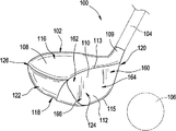
図1は、本発明の少なくともいくつかの例の、ゴルフドライバの形態の打球装置100の一例を示す。打球装置100は、打球ヘッド102および打球ヘッド102に接続され、そこから延びるシャフト104を含む。また、図1には、使用されるボール106が、打球装置100によって打たれる位置で示されている。
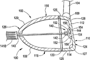
FIG. 1 shows an example of a ball
図1の打球装置100の打球ヘッド102は、ボディ108に接続されたフェース112を有し、ボディからホーゼル109が延びている。本発明を逸脱することなく、当技術分野において公知であり、使用されている従来のホーゼルおよび/またはヘッド/シャフト相互接続構造を含む任意の所望のホーゼルおよび/またはヘッド/シャフト相互接続構造を使用することができる。参照のために、ヘッド102は一般に、上部116、下部またはソール118、ホーゼル109に近接するヒール120、ホーゼル109から遠いトウ122、前面124および背面または後部126を有する。ヘッド102の形状および設計は、装置100の所期の用途によって部分的に決まることもある。図1に示すクラブ100において、クラブ100は、ボールを正確に遠くまで打つためのドライバまたはウッドタイプゴルフクラブとしての使用のために設計されているため、ヘッド102は相対的に大きな体積を有する。たとえば異なるタイプのゴルフクラブのための他の用途において、ヘッドは、異なる寸法および構成を有するように設計されてもよい。ドライバとして構成される場合、クラブヘッドは、少なくとも400cc、いくつかの構造においては少なくとも450ccまたはさらに少なくとも460ccの体積を有しうる。他のクラブヘッドの場合の他の適切なサイズは当業者によって容易に決定しうる。
1 has a
図1〜3に示す例示的態様において、ヘッド102は、内部キャビティを画定する中空構造(たとえば、フェース112およびボディ108によって画定される)を有する。したがって、ヘッド102は、その中に画定された複数の内面を有する。一つの態様において、中空の中心キャビティは空気で満たされてもよい。しかし、他の態様において、ヘッド102は、別の材料、たとえばフォームで満たされることもできる。なおさらなる態様においては、ヘッドの固形材料が体積の比較的大きな割合を占めてもよく、ヘッドは、より小さなキャビティを有する、または内部キャビティを全く有しないこともできる。いくつかの態様において、内部キャビティは完全には包囲されなくてもよいことが理解されよう。
In the exemplary embodiment shown in FIGS. 1-3, the
フェース112は、ヘッド102の前面124に位置し、その上に位置する打球面110を有する。打球面110は、使用中にボール106に対面するように構成され、たとえばスイングによって装置100が動かされたとき、ボール106を打つように適合されている。図示するように、打球面110は、相対的に平坦であり、フェース112の大部分を占める。参照のために、フェース上縁113およびヘッド102のヒール120に近いフェース112の部分を「ハイヒール区域」160と呼び、フェース上縁113およびヘッド102のトウ122に近いフェース112の部分を「ハイトウ区域」162と呼び、フェース下縁115およびヘッド102のヒール120に近いフェース112の部分を「ロウヒール区域」164と呼び、フェース下縁115およびヘッド102のトウ122に近いフェース112の部分を「ロウトウ区域」166と呼ぶ。概念的に、これらの区域160〜166は、実質的に等しいサイズの四分円(および/またはフェース112の幾何学的中心から延びる四分円)と認識することができるが、必ずしも対称な寸法を有するわけではない。フェース112は、当技術分野において公知であり、一般的であるように、上下方向および/またはヒール−トウ方向にいくらかのカーブ(たとえばバルジおよびロール特性)を含みうる。他の態様においては、表面110がフェース112の異なる割合を占めることもできるし、またはボディ108が、その上に多数の打球面110を有することもできる。図1に示す例示的態様において、打球面110はわずかに傾斜して(すなわちロフト角を有して)、打ったときにボール106にわずかなリフトおよびスピンを加える。他の例示的態様において、打球面110は、ボール106の弾道に影響するように異なる傾斜またはロフト角を有しうる。さらには、いくつかの態様において、フェース112は、可変性の厚さを有してもよく、および/または一つまたは複数の内部もしくは外部インサートを有してもよい。
The
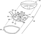
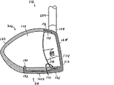
フェース112、ボディ108および/またはホーゼル109は、単一のピースとして形成されることもできるし、または接合される別々のピースとして形成されることもできることが理解されよう。一つの態様において、フェース112は、たとえば図2に示すようにフェースフレーム部材128の一部として形成され、フェース112の縁127から壁125が後方に延びている。この構成はカップフェース構造とも知られている。ボディ108は、フェースフレーム部材128の壁125に接合された別々のピースとして形成されることができる。図2に示す例示的態様において、ボディ108は、一つのピースまたは多数のピースであることができるバックボディ部材129によって部分的に形成されている。フェースフレーム部材128の壁125がバックボディ部材129と組み合わさってヘッド102のボディ108を形成する。これらのピースは、一体接合技術、たとえば溶接、セメンティングまたは接着剤接合によって接続されてもよい。これらのパーツを接合するための他の公知の技術を、解放可能な機械的係合技術を含む多くの機械的接合技術を含め、同様に使用することもできる。望むならば、ホーゼル109は、フェースフレーム部材128の一部として一体に形成されてもよい。さらには、図2に示すように、フェースフレーム部材128とバックボディ部材129との間にガスケット130が含まれてもよい。ガスケット130は、フェースフレーム部材128とバックボディ部材129との間に配置されたポリマー材料(たとえばゴム、ポリテトラフルオロエチレンまたは他の材料)または他の材料でありうる。
It will be appreciated that the
打球装置100は、図1に模式的に示すように、打球ヘッド102に接続または他のやり方で係合したシャフト104を含むことができる。シャフト104は、打球装置100をスイングしてボール106を打つためにユーザによって把持されるように適合されている。シャフト104は、図1に示すように、たとえばホーゼル109に接続することによってヘッド102に接続された別個のピースとして形成されることができる。他の例示的態様においては、シャフト104の少なくとも一部分がヘッド102と一体のピースであってもよいし、および/またはヘッド102は、ホーゼル109を含まなくてもよいし、または内部ホーゼル構造を含んでもよい。本発明の範囲を逸脱することなく、なおさらなる態様が考えられる。シャフト104は、金属、セラミックス、ポリマー、複合材または木を含む多様な材料の一つまたは複数から構築されうる。いくつかの例示的態様において、シャフト104または少なくともその部分は、金属、たとえばステンレス鋼または複合材、たとえばカーボン/グラファイト繊維・ポリマー複合材で構築されうる。しかし、本発明の範囲を逸脱することなく、シャフト104は、当技術分野において公知であり、使用されている従来の材料を含む様々な材料で構築されうる。
The ball
一般に、打球装置100のヘッド102は、フェース112の特定の区域または部分に増大した剛性を提供するための、フェース112に接続された一つまたは複数の移動可能な補剛要素を有する。一般に、補剛要素は、フェース112の内面114上の一つまたは複数の接触点と係合し、たとえばフェース112の内面114に力を加えることにより、その接触点および/またはその辺りで増大した剛性を提供する。さらには、補剛要素は移動可能であり、補剛要素の移動が接触点の場所を変える。接触点を変えることにより、フェース112の所望の区域が局所的に増大した剛性を有するようにヘッド102を調節して、上記のように、増大したフェース可撓性の一つまたは複数の標的領域の場所を制御することができる。
In general, the
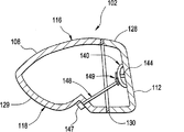
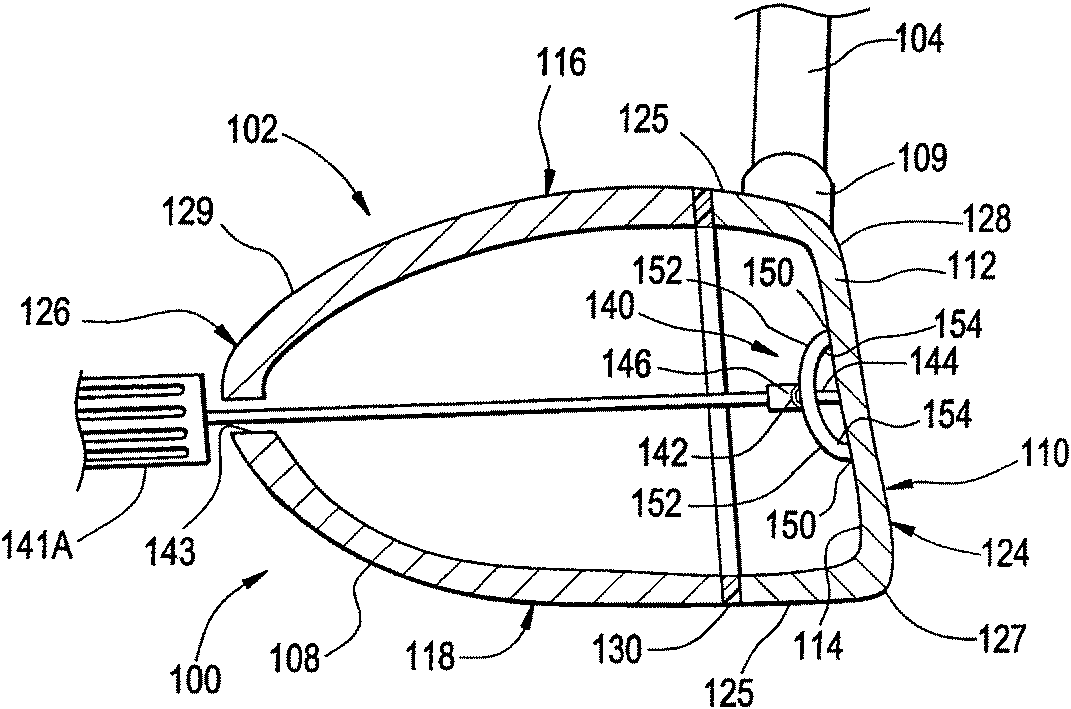
図2〜4は、フェース112の内面114に回転可能に接続される補剛要素140の一つの例示的態様を示す。この態様において、補剛要素140は、フェース112の内面114に取り付けられたピボット部材144によってフェース112の内面に接続される。ピボット部材144はフェース112の内面114に固着され、補剛要素はピボット部材144に回転可能に接続される。図示する例示的態様において、ピボット部材144はねじ込みピン144であり、補剛要素140はピボット部材144を中心に自由に回転可能である。図2〜4に示すように、ピボット部材144は補剛要素140のためのピボット点142を画定し、補剛要素140はピボット点142を中心に回転することができる。ねじ込みリテーナ、たとえばナット146がピボット部材144の端部に螺合して補剛要素140をピボット部材144に保定する。ナット146は、補剛要素140の回転を可能にするためにゆるめたのち、補剛要素140を定位置に保持するために締めることができる。したがって、ナット146は、リテーナとして、また、補剛要素140を回転に関してロックし、ロック解除するための要素として機能することができる。他の態様において、異なるタイプの保定構造および/またはロック/ロック解除構造をヘッド102に組み込むことができる。ナット146はまた、補剛要素140がより大きなまたは小さな圧力をフェース112の内面114に加えるように調節することもできる。
FIGS. 2-4 illustrate one exemplary embodiment of a
図2〜4に示す態様において、補剛要素140はヘッド102の外側からはアクセス不可能であり、補剛要素140にアクセスするために、ヘッド102の一部分を開放する、または取り外すことができる。たとえば、以下に説明するようにバックボディ部材129を取り外すこともできるし、またはヘッド102が、補剛要素140へのアクセスを許すために取り外し可能である(たとえばスナップ嵌めまたはねじ込みによって)キャップ、栓、ドアなどを有する開口をその中に有してもよい。さらには、補剛要素140、ピボット部材144および/またはナット146は、補剛要素140および/またはピボット部材144の回転を生じさせるための工具(たとえばスクリュードライバ、アレンレンチ、ソケットレンチなど)による係合のために構成されていてもよい。この態様に記載される固定および移動可能な接続は、当技術分野において公知であり、使用されている任意の接続を使用して、たとえば様々なファスナ、接着剤、バインダなどの使用によって達成することができることが理解されよう。別の例示的態様において、補剛要素140は、ねじ込みピン144への接続のためのねじ込み孔を含むことができ、ナット146は含まれてもよいし、含まれなくてもよい。さらなる例示的態様において、ピボット部材144は、ピボット部材144および補剛要素140の回転を許すためにフェース112に回転可能に接続されて、それにより、補剛要素140を回転させたり、および/または締め付けたりしうる。この態様において、回転可能なピボット部材144は、たとえば直接のアクセスによって(たとえばフェースを通して)、または以下に説明するように調節部材148によって、ピボット部材144を回転させるためにヘッド102の外側からアクセス可能である。さらなる例示的態様において、ピボット部材144はねじを有しなくてもよいし、または補剛要素140は、別のやり方でフェース112に回転可能に接続されてもよい。
In the embodiment shown in FIGS. 2-4, the
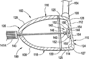
代替態様において、補剛要素140は、ヘッド102の外側からアクセス可能または他のやり方で調節可能でありうる。そのような実施態様の一つが、ヘッド102が、補剛要素140に操作可能に接続されている外部からアクセス可能な調節部材148を含む図5に示されている。調節部材148の回転が補剛要素140の回転を生じさせる。調節部材148は、ヘッド102の下部側118まで延び、下部118を通してアクセス可能である。図示する態様において、調節部材148および補剛要素140は、調節部材148による補剛要素140の回転を可能にする相補的な歯車接続149を有する。調節部材148は、調節部材148の操作のための工具による係合のために適合されていることができる端部147を有する。他のタイプの協働回転手段および構造、たとえば自在継手、ウォームギヤおよび他のそのような構造を使用して、調節部材148を補剛要素140に接続してもよい。さらには、補剛要素140をロック解除して回転を許し、そしてひとたび所望の位置に達したならば補剛要素140をロックするように操作することができるロックおよび/または保定構造、たとえば上記のナット146をヘッド102に組み込んでもよい。別の態様において、調節部材148は、異なる面、たとえばヘッド102の下部側118ではなく上部側116または後部126を通してアクセス可能であってもよく、さらに別の態様において、調節部材は、フェース112を通してアクセス可能であってもよい。さらなる代替態様において、調節部材148は、ピボット部材144に操作可能に接続されてピボット部材144の回転を生じさせてもよい。さらなる態様において、調節部材148は、たとえばボディ108の背面126まで延びることにより、ピボット部材144および/または補剛要素140と同軸であってもよい。
In alternative embodiments, the
代替態様において、補剛要素140の操作のためにヘッド102の外側から補剛要素140および/または保定/ロック構造(たとえばナット146)にアクセスするために一つまたは複数の専用工具が提供されうる。ヘッド102は、たとえばフェース112および/またはボディ108に開口を含めることにより、工具による外部からアクセスを許すように構成されうる。たとえば、工具は、ボディ108中の開口に通して使用することができる長い挿入工具であってもよい。上記のように、ヘッド102は、ロックおよび/または保定要素(たとえばナット146)を含んでもよく、ロック/保定要素および補剛要素140を別々に操作するために別々の工具が提供されてもよく、この別々の操作は順次に実施されてもよいし、同時に実施されてもよいということが理解されよう。たとえば、補剛要素およびロック/保定要素は、たとえば、補剛要素140およびナット146が同心的に回転可能である図2および3に示すように、同心的に移動可能であってもよく、ボディ108中の同じ開口を通して補剛要素140およびナット146を順次に操作するために一つまたは複数の工具が提供されてもよい。図5Aおよび5Bに示す一つの例示的態様において、補剛要素140およびナット146は、それぞれ、たとえば当技術分野において公知の多様なやり方における、別々の工具141A、141Bによる係合のために特別に適合されている。工具141A、141Bは、補剛要素140およびナット146を操作するために、フェース112またはボディ108中の同じ開口143に順次に挿入することができる。図5Aに示すように、第一の工具141Aを開口143に挿入してナット146をゆるめたのち、第二の工具141Bを開口143に挿入して補剛要素140を調節する。そして、第一の工具141Aを再び挿入してナット146を再び締め付けることができる。使用されていない開口143をふさぐために栓、ドア、インサートなどを提供してもよいことが理解されよう。補剛要素が異なる構成である他の態様においては、異なるタイプの工具が提供されうる。
In alternative embodiments, one or more dedicated tools may be provided to access the
図2〜4に示す補剛要素140は、補剛要素140とフェース112の内面114との間に四つの接触点150を有して、四つの局所的に増大した剛性の区域をフェース112上に創製している。この態様において、補剛要素140は、ピボット点142から略X字形に延びる四つのアーム152を有する。図示される補剛要素140の各アーム152は、フェース112の内面114から離間しており、各アーム152はその遠位末端に係合部材154を有する。係合部材154はフェース112の内面114と係合して接触点150を形成し、接触点150に力を加える。この態様において、係合部材154は、それぞれのアーム152の連続的かつ一体の部分である。しかし、別の態様において、係合部材154は、各アーム152とは対照的により明確に画定されてもよく(たとえば図6〜8のように)、補剛要素140上の他の場所に位置しうる。図3に示すように、補剛要素140を回転させると、接触点150を新たな場所150Aに変更することができる。図3の接触点150は、フェース112のハイセンター、ローセンター、ミッドヒールおよびミッドトウ領域が相対的に増大した可撓性を有するように局所的に増大した剛性の区域を配置する。接触点を場所150Aに配置する補剛要素140の回転は、フェース112のハイヒール、ハイトウ、ロウヒールおよびロウトウ区域が比較的増大した可撓性を有するように局所的に増大した剛性の区域の位置を変更する。図2〜4に示す例示的態様において、補剛要素140の回転は、接触点150すべてを同時に変更するが、他の態様において、補剛要素140は、接触点150のすべて未満を変更する、または指定された接触点150を選択的に変更するように構成されてもよい。
The
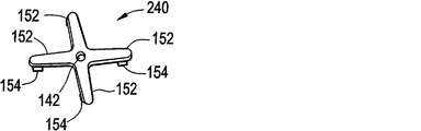
図6〜9は、図2〜4に示す上記補剛要素140にいくつかの点で似ている回転可能な補剛要素240、340、440、540の他の例示的態様を示す。図6に示す補剛要素240は、ピボット点142から略X字形に延びる四つのアーム152を有し、各アーム152は係合部材154をその遠位末端に有している。補剛要素240は、上記と同様にして、図2および3に示すピン144に似たピンの使用によってフェース112に接続可能である。補剛要素240は、図2〜4に示す補剛要素140とはわずかな構造的違いを有する。たとえば、補剛要素240は、アーム152に対して実質的に直角に延びる係合部材154を有する。
FIGS. 6-9 illustrate other exemplary embodiments of
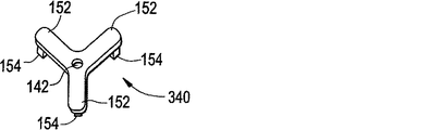
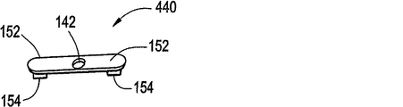
図7に示す補剛要素340および図8に示す補剛要素440は、図6に示す補剛要素240に似ているが、いくつかの構造的違いがある。たとえば、図7の補剛要素340は、ピボット点142から延びて、上記X字形構成ではなく略Y字形を形成する三つのアーム152を有する。同様に、図8の補剛要素440は、ピボット点142から相対的にまっすぐな線として延びる二つのアーム152を有する。図7の補剛要素340および図8の補剛要素440のアーム152は、図6の補剛要素240のアームと同様に構造化され、アーム152はアーム152に対して実質的に直角である係合部材154を有する。
The
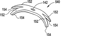
図9に示す補剛要素540は、上記補剛要素140に多くの点で似ている。補剛要素540は、中央ピボット点142から略X字形に延びる四つのアーム152を有する。また、補剛要素540は、上記ピン144およびナット146を使用してフェース112の内面114に接続するように構成されている。図9に示す補剛要素540と上記補剛要素140との一つの違いはその形である。図9の補剛要素540は、より堅く、より細長いX字形を有し、それが、図2〜4に示す補剛要素140とは異なる、局所的に増大した剛性を有する区域、および結果的には相対的に増大した可撓性の区域の分布を生じさせる。
The
図示される補剛要素140、240、340、440、540それぞれは、補剛要素140、240、340、440、540上のアーム152の先端に係合部材154を含む。しかし、他の構成が可能であることが理解されよう。たとえば、補剛要素は識別可能なアームを有しなくてもよく、補剛要素のより大きな部分がフェース112の内面114と接触してもよい。別の例として、係合部材はアームの先端に位置しなくてもよいし、および/または各アームが一つを超える係合部材を有してもよい。図示される補剛要素140、240、340、440、540の間の他の違いおよび類似点は当業者には明らかである。さらには、他の態様において、補剛要素140、240、340、440、540は、たとえば異なるやり方でフェースに接続する、またはアーム152の数および/または構成を変更することにより、異なるふうに構築されてもよい。たとえば、補剛要素は、所望により、T字形、V字形、C字形、I字形または任意の他の形状を有してもよい。
Each of the illustrated
さらなる態様において、ヘッド102は、上記補剛要素140、240、340、440、540に比較的似ていない回転可能な補剛要素を含みうる。一例として、回転可能な補剛要素は、たとえば、ピボット点142をX字形補剛要素のアームの一つの先端に配置することにより、回転非対称であってもよい。他の態様において、上記のように、補剛要素は、異なる構造を使用して、別のやり方でフェースに回転可能に接続されてもよい。いくつかの例として、フェース112および補剛要素は、いずれも補剛要素の回転を許すことができる、さねはぎ接続、クランピング構造または締まり嵌めによって接続されてもよい。回転可能な補剛要素のさらに他の構成が可能である。
In a further aspect, the
他の例示的態様において、ヘッド102は、回転可能ではない、異なるやり方で移動される移動可能な補剛要素を含みうる。たとえば、補剛要素は、滑動、軌道運動、ロール運動または任意の他の動きで移動することができる。補剛要素およびフェース112は、そのような動きを可能にするやり方で補剛要素をフェース112に接続するように相補的に構造化および構成されうることが理解されよう。なおさらに、ヘッド102は、一つを超える移動可能な補剛要素を含みうる。
In other exemplary aspects, the
さらなる態様において、移動可能な補剛要素は、フェース112に接続されなくてもよく、一つまたは複数の係合部材154を介して単にフェース112と係合してもよい。たとえば、補剛要素は、ボディ108との操作可能な接続、たとえばボディ108の内面から延びて補剛要素をフェース112と押し合わせるブレースによってフェースに押し当てることもできる。別の例として、補剛要素は、補剛要素をフェース112と押し合わせる、図5に示す調節部材148に似たものであってもよい調節部材に接続することもできる。様々な他の構成でフェース112と係合するように取り付けることができる様々な他のタイプの回転可能または他の移動可能な補剛要素が本発明の範囲に入ると考えられる。
In a further aspect, the movable stiffening element may not be connected to the
補剛要素の様々な態様は一般に、操作および調節のために、たとえばユーザ、機械または他の装置もしくは実体によって直接または間接的にアクセス可能である。一つの態様において、ヘッド102の内側に収容されている補剛要素へのアクセスを提供するために、ヘッド102のボディ108の一部分を取り外すことができる。本明細書に記載されるように、ボディ108の任意の部分の取り外しはさらに、非全体的または非永久的な取り外しを含む。たとえば、補剛要素へのアクセスを提供するためのボディ108中に形成されたスイング式またはスライド式ドアの開放は、その部分の取り外しを構成するが、その部分が完全に取り外されるわけではない。別の例として、後で再び接続することができるピースの取り外しもまた、取り外しを構成する。別の態様においては、ヘッドの外側からアクセス可能である調節部材、たとえば図5に示す上記調節部材148を使用して、補剛要素を操作してもよい。さらなる態様において、調節部材は、フェースを通して、またはヘッド102中のスロットもしくは開口を通してアクセスしてもよく、適切な工具によって操作されるように構成されることができる。
Various aspects of the stiffening element are generally directly or indirectly accessible for manipulation and adjustment, for example by a user, machine or other device or entity. In one embodiment, a portion of the
図2に示す態様において、バックボディ部材129は、補剛要素140へのアクセスを提供するために取り外し可能である。ひとたび補剛要素140を調節したならば、バックボディ部材129を再び取り付けることができる。さらには、複数の異なるバックボディ部材を提供することができ、それらすべてを、図2に示すバックボディ部材129の代わりにフェースフレーム部材128に取り付けることができる。バックボディ部材129を交換する能力が、ウェイト付け、ウェイト配分、空気力学などを含むクラブヘッドの様々な特徴および性質に対するより大きな制御を可能にする。同様に、ガスケット130が取り外し可能であり、同じく、たとえば様々な特性を提供する、または交換されたバックボディ部材と適合させるために、他のガスケットとで交換可能であってもよい。フェースフレーム部材128ならびに交換可能である複数の様々なバックボディ部材129および/またはガスケット130を含むキットまたはシステムを提供することができることが考えられる。
In the embodiment shown in FIG. 2, the
取り外し可能および/または交換可能なバックボディ部材のためのいくつかの異なる構成が、参照により本明細書に組み入れられ、本明細書の一部とされる2008年8月15日出願の米国特許出願第12/192,402号に示され、記載されている。たとえば、図10〜17は、カップフェース構造および取り外し可能なバックボディ部材を備えたフェースフレーム部材をそれぞれが含むゴルフクラブヘッド202、302、402、502の様々な態様を示す。 A number of different configurations for removable and / or replaceable back body members are incorporated herein by reference and are hereby incorporated by reference. This is shown and described in 12 / 192,402. For example, FIGS. 10-17 illustrate various aspects of golf club heads 202, 302, 402, 502 each including a face frame member with a cup face structure and a removable back body member.
図10〜11は、上記ヘッド102に似た多くの基本的特徴を含むヘッド202の一つのそのような例示的態様を示す。ヘッド202は、フェース112およびフェース112から後方に延びる壁125を有するカップフェース構造を備えたフェースフレーム部材128、ならびにフェースフレーム部材128に接続されたバックボディ部材129で形成されている。壁125は、ヘッド202のソール118上の延長ソール部分125Aを含む。
FIGS. 10-11 illustrate one such exemplary embodiment of a
ソール部分125Aは、フェース112の下縁から突出して、それにより、ヘッド202の後方部分120に向かって延びている。ソール部分125Aは、ヘッド202の後縁までずっと延びてもよい。一つの態様において、ソール部分125Aは、ヘッド202の前後長の半分を超えるところまで延びる。
The
バックボディ部材129は、フェースフレーム部材128に取り外し可能に取り付けられている。一つの局面において、図10〜11に具現化されているように、バックボディ部材129は中空のボディとして形成されている。図11でよく見てとれるように、バックボディ部材129は、その壁によって少なくとも部分的に包囲された内部凹所を含む。バックボディ部材129はさらに、フェースフレーム部材128に対面する開口を含む。例示される態様において、バックボディ部材129は、フェースフレーム部材128の壁125上の周フランジ172に相補的に挿入されるための周フランジ170を含む。バックボディ部材129がフェースフレーム部材128に取り付けられると、密閉または実質的に密閉された内部キャビティがヘッド202内に形成される。バックボディ部材129の周フランジ170がフェースフレーム部材128の周部材172にかぶさることができることが理解されよう。場合によっては、望むならば、ガスケットまたは他のそのような材料がバックボディ部材129とフェースフレーム部材128との接合部に提供されて(たとえば接合部の周囲に完全または部分的に)、ノイズまたは振動を減衰する、がたつきを減らす、封止を提供してもよい。
The
図10〜11の例示的態様において、バックボディ部材129は、ねじ込みファスナ174によってフェースフレーム部材128に取り外し可能かつ交換可能に結合される。図10〜11に示す態様においては、一つのねじ込みファスナ174がヘッド202のトウ側122に位置し、他方のねじ込みファスナ174がヒール側120に位置している。これらのねじ込みファスナそれぞれは、フェース112の面に対して略直角に向く縦軸を有する。バックボディ部材129は、ねじ込みファスナ174を適当な角度で挿入し、取り出すことを許すための座ぐり部分176を含む。図11でよく見てとれるように、この特定の態様においては、ファスナごとに、フェースフレーム部材128は、内側面に取り付けられた、または形成されたボス178を含む。ファスナ174のねじ込み部分の端部がボス178の中に、および/またはそれを越えて延びている。
In the exemplary embodiment of FIGS. 10-11, the
上記のように、図10〜11の態様のフェースフレーム部材128はソール部分125Aを含む。この例示的構造においては、弾性変形要素がバックボディ部材129をソール部分125Aに結合する。具体的には、ソール部分125Aの最後方端はタブ180を含む。タブ180は、バックボディ部材129中に画定されたスロット182に滑り込み、それにより、ソール部分125Aをバックボディ部材129の下部に結合するように設計されている。タブ180は弾性変形性であり、それにより、相補的なスロット182へのタブ180の挿入を促進し、さらに、フェースフレーム部材128に対するバックボディ部材129のかたよりを提供する。かたよりを使用して、二つの脱着可能に取り付けられた部材の間の望まれないあそびを除くことができる。当業者は、本開示の恩典を与えられると、他の締結機構を使用してソール部分125Aをバックボディ部材129に脱着可能に取り付けることができることを理解するであろう。
As described above, the
代替態様(図示せず)において、ソール部分125Aは、ねじ込みファスナによってソール部分125Aをバックボディ部材129に締結(たとえば、ボディ部材構造とともに含まれるボスまたは取り付けられたナット部材にねじ込まれる)されうるよう、その最後方端部に貫通孔を含んでもよい。
In an alternative embodiment (not shown), the
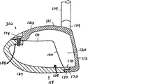
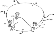
図12〜13に示すヘッド302の態様において、フェースフレーム部材128の壁125は、バックボディ部材129への接続のために適合されたクラウン部分125Bを含む。クラウン部分125Bはフェース112の上部分から後方に突出する。この特定の態様において、クラウン部分125Bはフェースフレーム部材128と一体に形成されている。クラウン部分125Bの最後方端部には、バックボディ部材129をフェースフレーム部材128に脱着可能に取り付けるためのねじ込みファスナ174が提供されている。望むならば、さらなるファスナが他の場所に提供されてもよい。
In the embodiment of the
バックボディ部材129は、その壁によって部分的に包囲された内部キャビティを含みうる。バックボディ部材129の後壁の上部分が内向きに延び、ファスナ174のねじ込み部分を受けるためのプラットフォーム184を提供している。バックボディ部材129の下部分では、フランジ170が、フェースフレーム部材128の壁125に形成された相補的なフランジ172と重なり合っている。この態様において、剥離可能な液化性接着剤の層130が二つのフランジ170、172の間に位置してガスケットとして機能する。さらには、剥離可能な液化性接着剤の層130は、フェースフレーム部材128の側壁およびクラウン部分に沿って上に延び、そこでバックボディ部材129と対面している。バックボディ部材129をフェースフレーム部材128から切り離すためには、ファスナ174を取り外したのち、剥離性接着剤を融解するまで加熱する。接着剤が液化すると、バックボディ部材129がフェースフレーム部材128から容易に滑り出すよう、バックボディ部材129をフェースフレーム部材128から剥がす。部材128、129は、接着剤なしで接続することもできるし、接着剤の代わりに異なるタイプのガスケットを用いて接続することもできることが理解されよう。
The
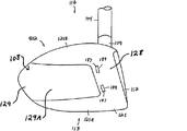
図14〜15に示すヘッド402の態様において、フェースフレーム部材128は、フェース112およびフェース112から後方に延びる壁125を含むカップフェース構造を有する。壁125はクラウン部分125Bおよびソール部分125Aを含む。バックボディ部材129は、その壁によって部分的に包囲された凹所を含む。この態様において、壁は、略U字形の凹所の囲いを形成し、二つの側壁129Aが後方壁部分から前方に延びている。クラウン部分125Bはフェース112の上部分から後方に突出している。ソール部分125Aはフェース112の下部分から後方に突出している。この特定の態様において、クラウン部分125Bおよびソール部分125Aはいずれもフェースフレーム部材128と一体に形成されている。
In the embodiment of the
図15でよく見てとれるように、クラウン部分125Bの最後方端部には、第一のピン186aの一部分を受けるための貫通孔が設けられている。第一のピン186aの異なる部分を受けるための対応する貫通孔がバックボディ部材129の上後方部分に設けられている。ソール部分125Aの最後方端部には、第二のピン186bの一部分を受けるための貫通孔が設けられている。第二のピン186bの異なる部分を受けるための対応する貫通孔がバックボディ部材129の下後方部分に設けられている。ピン186a、186bは、バックボディ部材129の後方部分をフェースフレーム部材128の後方部分(すなわち、クラウン部分125Bの後方部分およびソール部分125Aの後方部分)に取り外し可能に取り付ける。この特定の態様において、ピン186a、186bは弾性変形性ロールまたはスプリングピンである。場合によっては、別の態様において、ピン186a、186bは、塑性変形性スリーブおよび中央の(本質的に)非変形性ピンを含んでもよい。
As can be clearly seen in FIG. 15, a through hole for receiving a part of the first pin 186a is provided at the rearmost end portion of the crown portion 125B. Corresponding through holes for receiving different portions of the first pin 186a are provided in the upper rear portion of the
この特定の態様において、バックボディ部材129の側壁129Aの最前方端部には、一対のタブ188が提供されている。タブ188は、バックボディ部材129の残り部分と同じ材料で形成されてもよく、さらに、バックボディ部材129と一体に形成されてもよい。取り付けられた構成において、タブ188は、フェースフレーム部材128の側壁の内面に沿って位置する。各タブ188は、フェースフレーム部材128の側壁に向かって外方に延び、フェースフレーム部材128の開口189と係合する突起187を含む。図15においては、突起187はタブ188の反対側に位置するため、この図は突起187の輪郭を破線で示す。
In this particular embodiment, a pair of
バックボディ部材129をフェースフレーム部材128から切り離す場合には、たとえばピンドライバを用いてピン186a、186bをキャビティに打ち込む。次いで、工具を使用して突起187を内方に押すことによるか、またはバックボディ部材129の側壁129Aを互いに向けて絞ることによるかのいずれかで、突起187を開口189から係合解除する。当然、望むならば、図14〜15に示す様々なクラブヘッドコンポーネントは、他のタイプのコネクタ、たとえば上記ねじ込み機械的コネクタを使用して接続してもよい。
When the
任意の数の締結要素をゴルフクラブヘッドに提供することができ、本明細書に記載される締結要素の場所および向きは単に例示的であるということが理解されよう。本開示の恩典を与えられると、バックボディ部材129をフェースフレーム部材128に脱着可能に取り付けるための他の適当な方法が当業者には明らかであろう。
It will be appreciated that any number of fastening elements may be provided to the golf club head, and the location and orientation of the fastening elements described herein are merely exemplary. Given the benefits of the present disclosure, other suitable methods for removably attaching the
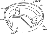
図16〜17に示すヘッド502の態様において、フェースフレーム部材128は、フェース112およびフェース112から後方に延びる壁125を含むカップフェース構造を有する。壁125はソール部分125Aおよびクラウン部分125Bを含み、実質的にフェース112とは反対側の後面190で終端している。バックボディ部材129がフェースフレーム部材128の後面190に脱着可能に取り付けられている。図16〜17に示す態様において、バックボディ部材129は、フェースフレーム部材128の後面190全体およびヘッド502のソール118の一部分に延びている。図16でよく見てとれるように、バックボディ部材129の外部ソール部分125Aの部分は、フェースフレーム部材128のソール部分125Aのいずれの側にも延びている。
In the embodiment of the head 502 shown in FIGS. 16-17, the
三つのファスナ174がバックボディ部材129をフェースフレーム部材128に機械的に締結する。ファスナ174は、ソール部分125Aに対して概して直角に、すなわち、ヘッド502が打球位置にあるときには垂直に延びる。三つのファスナが示されているが、より少数または多数のファスナを使用してバックボディ部材129をフェースフレーム部材128に取り付けてもよい。
Three
図17に示すように、後面190は、バックボディ部材129のアタッチメントを収容するように形成または成形されることができ、たとえば、後面190はファスナ174を収容するためのボスを含むことができる。この態様において、バックボディ部材129は、内部凹所がその中に画定されるような実質的に貝殻状の構造として形成されている。したがって、バックボディ部材129がフェースフレーム部材128に取り付けられると、包囲された、または実質的に包囲された二次ボディキャビティがそれらの間に形成される。
As shown in FIG. 17, the
図1〜3に示すヘッド102に関して上記したように、上記ヘッド202、302、402、502のバックボディ部材129は、取り外し、再び接続することができ、このことは、補剛要素の調節を可能にするだけでなく、ヘッド102を複数の様々なヘッド202、302、402、502の一つとで交換することをも可能にする。同じく上記のように、ヘッド202、302、402、502は、同じく取り外し、交換することができるガスケット、たとえば上記ガスケット130を含んでもよい。打球ヘッドのさらに他の態様は、他の機構によって、他の構造的構成を使用して取り外し可能であるヘッドの部分を有してもよく、そのような態様が本発明に範囲に含まれるということが理解されよう。
As described above with respect to the
本明細書に記載される打球ヘッド102(以下参照)は、フェースまたはその区域の可撓性に影響するさらなる特徴を有することができることが理解されよう。たとえば、ヘッド102(以下参照)は、相対的に増大または減少したフェース厚さの区域を有することができる。さらには、本明細書に記載されるヘッド102(以下参照)は、より多数または少数の補剛要素を含み、相対的な剛性および可撓性のさらなる区域を創製しうる。多数の補剛要素を有する態様においては、様々な補剛要素が異なる材料で形成されてもよいし、または加工技術によって特定の性質を有するように補強または他のやり方で設計されてもよいことが考えられる。 It will be appreciated that the ball striking head 102 (see below) described herein may have additional features that affect the flexibility of the face or area thereof. For example, the head 102 (see below) can have areas of relatively increased or decreased face thickness. Furthermore, the head 102 (see below) described herein may include more or fewer stiffening elements to create additional areas of relative stiffness and flexibility. In embodiments having multiple stiffening elements, the various stiffening elements may be formed of different materials, or may be reinforced or otherwise designed to have specific properties by processing techniques. Can be considered.
本明細書に開示される補剛要素140(以下参照)を組み込むヘッド102(以下参照)は、打球装置またはその一部として使用されうる。たとえば、図1に示すゴルフクラブ100は、シャフトまたはハンドル104を、提供されるヘッド、たとえば上記のようなヘッド102に取り付けることによって製造しうる。本明細書で使用される、ヘッドを「提供する」とは、広く、物品を、その物品に対して実施される将来の動作のために利用可能またはアクセス可能にすることをいい、その物品を提供する当事者がその物品を製造、生産または供給したこと、あるいはその物品を提供する当事者がその物品の所有権または管理を有することを意味しない。他の態様において、本明細書に記載される原理にしたがって様々なタイプの打球装置を製造することができる。ヘッド102を製造することは、上記のように、バックボディ部材129をフェースフレーム部材128に取り付けることを含みうる。さらには、ヘッド102(以下参照)、ゴルフクラブ100または他の打球装置は、補剛要素140(以下参照)を調節することによって人にフィッティングまたはカスタマイズすることができる。そのような調節は、補剛要素140(以下参照)の手動または機械的な操作を含みうる。いくつかの態様において、上記のように、補剛要素の調節は、ヘッドの一部分の取り外し、たとえばバックボディ部材129の取り外しを含むことがある。さらには、いくつかの態様において、ヘッド102(以下参照)、ゴルフクラブ100または他の打球装置のカスタマイズは、バックボディ部材129および/またはガスケット130を取り外し、複数の他の様々なバックボディ部材および/またはガスケットの一つとで交換することを含むことができる。
Head 102 (see below) incorporating stiffening element 140 (see below) disclosed herein may be used as a ball striking device or part thereof. For example, the
本明細書に記載されるような打球装置およびそのためのヘッドは、既存の製品に対して多くの恩典および利点を提供する。たとえば、補剛要素は、ヘッドのフェースに局所的剛性および可撓性を提供して、規制当局によって規定されたCOR制限を超えることなく、フェースの特定の区域が他の区域よりも高いCORを有するように戦略的に配置し、調節することができる。ヘッドは、プレー中にもっとも頻繁にボールと衝突するフェースの区域がより高いCORを有するように構成され、調節されることができる。フェース上のそのような特定の場所に衝突するボールは、より多くのエネルギーおよび速度をそこに伝達され、したがって、より長いヒットを生じさせる。さらには、補剛要素の場所ならびにその結果としての局所的剛性および可撓性の区域は、衝突したボールの方向、弾道およびスピンに影響することができる。したがって、ヘッドは、プレー中にもっとも頻繁にボールと衝突するフェースの区域がよりまっすぐでより忠実なボールの飛びを生じさせるように構成され、調節されることができる。 The ball striking device and the head therefor as described herein provide many benefits and advantages over existing products. For example, stiffening elements provide local stiffness and flexibility to the face of the head so that certain areas of the face have a higher COR than other areas without exceeding the COR limits set by regulatory authorities. Can be strategically arranged and adjusted to have. The head can be configured and adjusted so that the area of the face that most frequently impacts the ball during play has a higher COR. A ball that hits such a specific location on the face will transfer more energy and velocity there, thus producing a longer hit. Furthermore, the location of the stiffening element and the resulting local stiffness and flexibility area can affect the direction, trajectory and spin of the impacted ball. Thus, the head can be configured and adjusted so that the area of the face that most frequently collides with the ball during play causes the ball to fly straighter and more faithful.
本発明を実施する好ましい形態を含む具体例に関して本発明を詳細に説明したが、当業者は、上記システムおよび方法の数多くの変形および入れ替えがあることを理解するであろう。したがって、本発明の真意および範囲は、請求の範囲に述べられるように広義に解釈されるべきである。 Although the present invention has been described in detail with reference to specific examples including preferred forms of implementing the invention, those skilled in the art will appreciate that there are numerous variations and permutations of the systems and methods described above. Accordingly, the spirit and scope of the invention should be construed broadly as set forth in the claims.
Claims (40)
該フェースに接続されたボディ、および
該フェースの内面上の接触点と係合する移動可能な補剛要素
を含む、ゴルフクラブヘッド。 A face having an outer surface configured to strike a ball;
A golf club head comprising: a body connected to the face; and a movable stiffening element that engages a contact point on the inner surface of the face.
該フェース部材の該壁に接続されたバックボディ部材
をさらに含み、
該バックボディ部材および該フェース部材の該壁の少なくとも一部分がボディを画定し、該バックボディ部材が、移動可能な補剛要素へのアクセスを提供するために取り外し可能である、
請求項1記載のゴルフクラブヘッド。 A face member including a face and a wall extending rearward from the face; and a back body member connected to the wall of the face member;
At least a portion of the back body member and the wall of the face member define a body, the back body member being removable to provide access to a movable stiffening element;
2. The golf club head according to claim 1.
各バックボディ部材が該フェース部材に接続された場合に、それぞれが該バックボディ部材の一つまたは複数と該フェース部材の該壁との間に配置されるように構成された複数の異なるガスケット
をさらに含み、
該バックボディ部材それぞれおよび該ガスケット部材それぞれが、該フェース部材への接続ののち、取り外し可能かつ交換可能である、
請求項16記載のゴルフクラブヘッド。 A plurality of different back body members, each configured to be connected to a wall of the face member, and each back body member when connected to the face member, each with one or more of the back body members A plurality of different gaskets configured to be disposed between the wall of the face member;
Each of the back body members and each of the gasket members is removable and replaceable after connection to the face member;
17. A golf club head according to claim 16.
該フェースの外周から後方に延びる壁、および
該フェースの内面上の接触点と係合して、該接触点に近接する該フェースの区域に増大した剛性を提供する移動可能な補剛要素
を含む、打球装置において使用するためのフェース部材。 A face having an outer surface configured to strike a ball and an inner surface located opposite the outer surface behind the outer surface;
A wall extending rearward from the outer periphery of the face, and a movable stiffening element that engages a contact point on the inner surface of the face to provide increased stiffness to an area of the face proximate to the contact point A face member for use in a ball striking device.
該フェースの該内面上の該接触点を変えるために該補剛要素を移動させる工程を含む、方法。 Increased stiffness in a face having an outer surface configured to strike a ball, a body connected to the face, and a contact point on the inner surface of the face to proximate the contact point A method for using a golf club head including a movable stiffening element that provides
Moving the stiffening element to change the point of contact on the inner surface of the face.
該補剛要素を移動させる前に該ボディの該一部分を取り外す工程、および
該補剛要素を移動させたのち該ボディの該一部分を再び接続する工程。
。 30. The method of claim 29, further comprising the following steps wherein a portion of the body is removable to provide access to the movable stiffening element:
Removing the portion of the body prior to moving the stiffening element, and reconnecting the portion of the body after moving the stiffening element.
.
該補剛要素を移動させる前に該バックボディ部材を取り外す工程、ならびに
該補剛要素を移動させたのち該バックボディ部材を再び接続する工程。 The golf club head further includes a face member including a face and a wall extending rearwardly from the face, and a back body member connected to the wall of the face member, wherein at least one of the back body member and the wall of the face member 30. The method of claim 29, further comprising the following steps wherein a portion defines a body and the back body member is removable to provide access to a movable stiffening element.
Removing the back body member before moving the stiffening element, and reconnecting the back body member after moving the stiffening element.
該バックボディ部材および該ガスケットの少なくとも一つを取り外す工程、ならびに
該バックボディ部材および該ガスケットの該少なくとも一つを交換バックボディ部材および交換ガスケットの少なくとも一つで交換する工程。 A golf club head includes a face member including a face and a wall extending rearward from the face, a back body member connected to the wall of the face member, and between the back body member and the wall of the face member And at least a portion of the wall of the back body member and the face member defines a body, and the back body member is removable to provide access to a movable stiffening element 30. The method of claim 29, further comprising the following steps:
Removing at least one of the back body member and the gasket, and replacing the at least one of the back body member and the gasket with at least one of a replacement back body member and an exchange gasket.
該フェースに接続されたボディ、および
ピボット点で該フェースに接続され、該フェースと係合して該フェース上に増大した剛性の区域を創製する回転可能な補剛要素
を含む、ゴルフクラブヘッド。 A face having an outer surface configured to strike a ball;
A golf club head comprising: a body connected to the face; and a rotatable stiffening element connected to the face at a pivot point to engage the face and create an increased stiffness area on the face.
Applications Claiming Priority (3)
| Application Number | Priority Date | Filing Date | Title |
|---|---|---|---|
| US12/261,875 US7967700B2 (en) | 2008-10-30 | 2008-10-30 | Golf club head or other ball striking device having adjustable stiffened face portion |
| US12/261,875 | 2008-10-30 | ||
| PCT/US2009/062599 WO2010059382A2 (en) | 2008-10-30 | 2009-10-29 | Golf club head or other ball striking device having adjustable stiffend face portion |
Publications (2)
| Publication Number | Publication Date |
|---|---|
| JP2012507367A true JP2012507367A (en) | 2012-03-29 |
| JP5438124B2 JP5438124B2 (en) | 2014-03-12 |
Family
ID=42132110
Family Applications (1)
| Application Number | Title | Priority Date | Filing Date |
|---|---|---|---|
| JP2011534775A Expired - Fee Related JP5438124B2 (en) | 2008-10-30 | 2009-10-29 | Golf club head or other ball striking device having adjustable stiffening face portion |
Country Status (5)
| Country | Link |
|---|---|
| US (2) | US7967700B2 (en) |
| EP (1) | EP2349504B1 (en) |
| JP (1) | JP5438124B2 (en) |
| CN (1) | CN102245267B (en) |
| WO (1) | WO2010059382A2 (en) |
Cited By (1)
| Publication number | Priority date | Publication date | Assignee | Title |
|---|---|---|---|---|
| JP2014111170A (en) * | 2009-11-11 | 2014-06-19 | Acushnet Co | Golf club head with replaceable head |
Families Citing this family (58)
| Publication number | Priority date | Publication date | Assignee | Title |
|---|---|---|---|---|
| US9498688B2 (en) | 2006-10-25 | 2016-11-22 | Acushnet Company | Golf club head with stiffening member |
| US7967700B2 (en) * | 2008-10-30 | 2011-06-28 | Nike, Inc. | Golf club head or other ball striking device having adjustable stiffened face portion |
| US8608585B2 (en) * | 2009-04-27 | 2013-12-17 | Nike, Inc. | Golf club head or other ball striking device having a reinforced or localized stiffened face portion |
| US8187116B2 (en) * | 2009-06-23 | 2012-05-29 | Nike, Inc. | Golf clubs and golf club heads |
| US8210961B2 (en) * | 2010-02-19 | 2012-07-03 | Nike, Inc. | Golf club or golf club head having an adjustable ball striking face |
| US8574092B2 (en) * | 2010-09-30 | 2013-11-05 | Callaway Golf Company | Golf club head with articulated hosel |
| US9597562B2 (en) | 2011-12-23 | 2017-03-21 | Taylor Made Golf Company, Inc. | Iron type golf club head |
| US9079078B2 (en) * | 2011-12-29 | 2015-07-14 | Taylor Made Golf Company, Inc. | Golf club head |
| JP2015517880A (en) * | 2012-05-31 | 2015-06-25 | ナイキ イノベイト セー. フェー. | Golf club having a ball striking plate with thin spoke-like reinforcing ribs |
| US9987527B1 (en) * | 2012-06-27 | 2018-06-05 | Callaway Golf Company | Iron-type golf club head with stiffening rods |
| US10016662B1 (en) | 2014-05-21 | 2018-07-10 | Taylor Made Golf Company, Inc. | Golf club |
| JP6363406B2 (en) | 2014-06-13 | 2018-07-25 | ブリヂストンスポーツ株式会社 | Golf club head |
| CN104190055A (en) * | 2014-08-19 | 2014-12-10 | 中山市迈进高尔夫用品有限公司 | Golf ball hitting head |
| US12179072B2 (en) | 2014-08-26 | 2024-12-31 | Parsons Extreme Golf, Llc | Golf club heads and methods to manufacture golf club heads |
| US11697050B2 (en) | 2014-08-26 | 2023-07-11 | Parsons Xtreme Golf, LLC | Golf club heads and methods to manufacture golf club heads |
| US11000742B2 (en) | 2014-08-26 | 2021-05-11 | Parsons Xtreme Golf, LLC | Golf club heads and methods to manufacture golf club heads |
| US9669270B2 (en) | 2014-08-26 | 2017-06-06 | Parsons Xtreme Golf, LLC | Golf club heads and methods to manufacture golf club heads |
| US10532257B2 (en) | 2014-08-26 | 2020-01-14 | Parsons Xtreme Golf, LLC | Golf club heads and methods to manufacture golf club heads |
| US12121782B2 (en) | 2014-08-26 | 2024-10-22 | Parsons Xtreme Golf, LLC | Golf club heads and methods to manufacture golf club heads |
| JP6786267B2 (en) * | 2016-06-15 | 2020-11-18 | ブリヂストンスポーツ株式会社 | Golf club head |
| US11020639B2 (en) | 2016-07-26 | 2021-06-01 | Acushnet Company | Golf club having an elastomer element for ball speed control |
| US11826620B2 (en) | 2016-07-26 | 2023-11-28 | Acushnet Company | Golf club having a damping element for ball speed control |
| US10625127B2 (en) | 2016-07-26 | 2020-04-21 | Acushnet Company | Golf club having an elastomer element for ball speed control |
| US12370425B2 (en) | 2016-07-26 | 2025-07-29 | Acushnet Company | Golf club having a damping element for ball speed control |
| US11433284B2 (en) | 2016-07-26 | 2022-09-06 | Acushnet Company | Golf club having a damping element for ball speed control |
| US11202946B2 (en) | 2016-07-26 | 2021-12-21 | Acushnet Company | Golf club having a damping element for ball speed control |
| US10086244B2 (en) * | 2016-07-26 | 2018-10-02 | Acushnet Company | Golf club having an elastomer element for ball speed control |
| US12377329B2 (en) | 2016-07-26 | 2025-08-05 | Acushnet Company | Golf club having a damping element for ball speed control |
| US11794080B2 (en) | 2016-07-26 | 2023-10-24 | Acushnet Company | Golf club having a damping element for ball speed control |
| US10821338B2 (en) | 2016-07-26 | 2020-11-03 | Acushnet Company | Striking face deflection structures in a golf club |
| US11786789B2 (en) | 2016-07-26 | 2023-10-17 | Acushnet Company | Golf club having a damping element for ball speed control |
| US12145038B2 (en) | 2016-07-26 | 2024-11-19 | Acushnet Company | Golf club having a damping element for ball speed control |
| US11938387B2 (en) | 2016-07-26 | 2024-03-26 | Acushnet Company | Golf club having a damping element for ball speed control |
| US20230042378A1 (en) | 2016-07-26 | 2023-02-09 | Acushnet Company | Golf club having a damping element for ball speed control |
| US12643022B2 (en) | 2016-07-26 | 2026-06-02 | Acushnet Company | Golf club having a damping element for ball speed control |
| US12478846B2 (en) | 2016-07-26 | 2025-11-25 | Acushnet Company | Golf club having a damping element for ball speed control |
| US11484756B2 (en) | 2017-01-10 | 2022-11-01 | Parsons Xtreme Golf, LLC | Golf club heads and methods to manufacture golf club heads |
| US11654338B2 (en) | 2017-01-10 | 2023-05-23 | Parsons Xtreme Golf, LLC | Golf club heads and methods to manufacture golf club heads |
| US11617925B2 (en) | 2019-03-11 | 2023-04-04 | Parsons Xtreme Golf, LLC | Golf club heads and methods to manufacture golf club heads |
| US12290725B2 (en) | 2017-01-10 | 2025-05-06 | Parsons Xtreme Golf, LLC | Golf club heads and methods to manufacture golf club heads |
| US10413789B1 (en) * | 2017-11-22 | 2019-09-17 | Callaway Golf Company | Golf club head with face damping and stress-reduction features |
| US20220387864A1 (en) * | 2018-05-25 | 2022-12-08 | Parsons Xtreme Golf, LLC | Golf club heads and methods to manufacture golf club heads |
| TWI671099B (en) * | 2018-07-17 | 2019-09-11 | 明安國際企業股份有限公司 | Golf club head hitting panel |
| US11219805B2 (en) | 2018-07-23 | 2022-01-11 | Acushnet Company | Multi-material golf club head |
| US10653927B2 (en) | 2018-07-23 | 2020-05-19 | Acushnet Company | Multi-material golf club head |
| CN110856767A (en) * | 2018-08-15 | 2020-03-03 | 明安国际企业股份有限公司 | Striking panel of golf club head |
| US11839799B2 (en) | 2019-01-02 | 2023-12-12 | Parsons Xtreme Golf, LLC | Golf club heads and methods to manufacture golf club heads |
| US11806589B2 (en) * | 2019-03-11 | 2023-11-07 | Parsons Xtreme Golf, LLC | Golf club heads and methods to manufacture golf club heads |
| US12434112B2 (en) | 2019-03-11 | 2025-10-07 | Parsons Xtreme Golf, LLC | Golf club heads and methods to manufacture golf club heads |
| US11839798B2 (en) | 2019-03-11 | 2023-12-12 | Parsons Xtreme Golf, LLC | Golf club heads and methods to manufacture golf club heads |
| US11771962B2 (en) | 2020-08-21 | 2023-10-03 | Wilson Sporting Goods Co. | Faceplate of a golf club head |
| US11806592B2 (en) * | 2020-12-23 | 2023-11-07 | Bridgestone Sports Co., Ltd. | Golf club head and method of manufacturing same |
| US11318358B1 (en) | 2020-12-29 | 2022-05-03 | Taylor Made Golf Company, Inc. | Golf club heads |
| US11813506B2 (en) | 2021-08-27 | 2023-11-14 | Acushnet Company | Golf club damping |
| US11679313B2 (en) | 2021-09-24 | 2023-06-20 | Acushnet Company | Golf club head |
| US12611577B2 (en) | 2021-09-24 | 2026-04-28 | Acushnet Company | Golf club head |
| US12179077B2 (en) | 2022-07-14 | 2024-12-31 | Acushnet Company | Internally damped golf club head |
| KR20250065923A (en) * | 2022-09-21 | 2025-05-13 | 카스턴 매뉴팩츄어링 코오포레이숀 | Golf club head with elastic member |
Citations (3)
| Publication number | Priority date | Publication date | Assignee | Title |
|---|---|---|---|---|
| US20030190975A1 (en) * | 2002-04-04 | 2003-10-09 | Skis Rossignol S.A. | Golf club head of iron or wood type |
| US20050009624A1 (en) * | 2003-05-27 | 2005-01-13 | Long Dabbs Clayton | Golf club head with a stiffening plate |
| JP2007044279A (en) * | 2005-08-10 | 2007-02-22 | Daiwa Seiko Inc | Golf club |
Family Cites Families (52)
| Publication number | Priority date | Publication date | Assignee | Title |
|---|---|---|---|---|
| US1665523A (en) * | 1928-01-07 | 1928-04-10 | Edward C Boyce | Golf club |
| US2175598A (en) * | 1938-09-27 | 1939-10-10 | Fedak Malcolm | Adjustable golf club head |
| US2171383A (en) * | 1938-10-12 | 1939-08-29 | William L Wettlaufer | Golf club head |
| US2652256A (en) * | 1951-09-14 | 1953-09-15 | Wilbur H Thomas | Whip action device for the head of golf clubs |
| US3589731A (en) * | 1969-12-29 | 1971-06-29 | Chancellor Chair Co | Golf club head with movable weight |
| US4067572A (en) * | 1976-08-05 | 1978-01-10 | Coleman Marvin W | Golf club |
| US4535990A (en) * | 1982-11-24 | 1985-08-20 | Daiwa Golf Co., Ltd. | Golf club head |
| US4461481A (en) * | 1983-01-31 | 1984-07-24 | Kim Sunyong P | Golf club of the driver type |
| US4878672A (en) * | 1987-05-26 | 1989-11-07 | Ram Golf Corporation | Golf club with swing speed indicator |
| US4951948A (en) * | 1989-04-17 | 1990-08-28 | Peng Jung C | Shock absorbing bat |
| JPH0716534B2 (en) * | 1990-01-29 | 1995-03-01 | 剛一郎 松崎 | Golf club |
| JPH0596033A (en) * | 1991-10-04 | 1993-04-20 | Takeshi Hayashi | Iron golf club |
| JPH05269224A (en) * | 1992-03-26 | 1993-10-19 | Janome Sewing Mach Co Ltd | Golf club head |
| JPH07231957A (en) | 1994-02-22 | 1995-09-05 | Kozaburo Katsura | Golf club head |
| US5464211A (en) * | 1994-09-19 | 1995-11-07 | Atkins, Sr.; Clyde | Golf club head |
| US5683309A (en) * | 1995-10-11 | 1997-11-04 | Reimers; Eric W. | Adjustable balance weighting system for golf clubs |
| US5916042A (en) * | 1995-10-11 | 1999-06-29 | Reimers; Eric W. | Adjustable balance weighting system for golf clubs |
| US5890973A (en) * | 1995-11-17 | 1999-04-06 | Gamble; Christopher L. | Golf club |
| US5669829A (en) * | 1996-07-31 | 1997-09-23 | Pro Saturn Industrial Corporation | Golf club head |
| US6514154B1 (en) * | 1996-09-13 | 2003-02-04 | Charles A. Finn | Golf club having adjustable weights and readily removable and replaceable shaft |
| JPH10234889A (en) * | 1997-02-28 | 1998-09-08 | Shinichi Yamagata | Golf club |
| CN1255873A (en) * | 1998-01-16 | 2000-06-07 | 美津浓株式会社 | Metal golf club head |
| US6015354A (en) * | 1998-03-05 | 2000-01-18 | Ahn; Stephen C. | Golf club with adjustable total weight, center of gravity and balance |
| JP3009657B1 (en) * | 1998-11-10 | 2000-02-14 | 株式会社ナニワ製作所 | Golf club putter head |
| US6095931A (en) * | 1998-12-28 | 2000-08-01 | Callaway Golf Company | Bi-material golf club head having an isolation layer |
| KR100277745B1 (en) * | 1999-05-03 | 2000-12-15 | 김성철 | Golf putter |
| US6739983B2 (en) * | 1999-11-01 | 2004-05-25 | Callaway Golf Company | Golf club head with customizable center of gravity |
| US6491592B2 (en) * | 1999-11-01 | 2002-12-10 | Callaway Golf Company | Multiple material golf club head |
| US6348013B1 (en) * | 1999-12-30 | 2002-02-19 | Callaway Golf Company | Complaint face golf club |
| US6299547B1 (en) * | 1999-12-30 | 2001-10-09 | Callaway Golf Company | Golf club head with an internal striking plate brace |
| US6458043B1 (en) * | 2001-04-18 | 2002-10-01 | Acushnet Company | Golf club head with multi-radius face |
| JP2002320692A (en) * | 2001-04-26 | 2002-11-05 | Tsutae Nagashima | Golf club |
| US6602149B1 (en) * | 2002-03-25 | 2003-08-05 | Callaway Golf Company | Bonded joint design for a golf club head |
| US6648774B1 (en) * | 2002-05-01 | 2003-11-18 | Callaway Golf Company | Composite golf club head having a metal striking insert within the front face wall |
| US20030220157A1 (en) * | 2002-05-23 | 2003-11-27 | Dennis Tool Company | Golf club head with highly polished hard contact fact |
| JP2004033536A (en) * | 2002-07-04 | 2004-02-05 | Univ Waseda | Golf club head |
| US7108611B2 (en) * | 2002-12-19 | 2006-09-19 | Macilraith Steve | Individually customized golf club and process |
| JP2004237039A (en) * | 2003-02-03 | 2004-08-26 | Hisao Tanaka | Hitting game club |
| US7108609B2 (en) * | 2003-07-10 | 2006-09-19 | Nike, Inc. | Golf club having a weight positioning system |
| US20050014574A1 (en) * | 2003-07-15 | 2005-01-20 | Lung-Te Sung | Golf club head |
| US6964617B2 (en) * | 2004-04-19 | 2005-11-15 | Callaway Golf Company | Golf club head with gasket |
| US7140977B2 (en) * | 2004-06-04 | 2006-11-28 | Atkins Technology, Inc. | Golf club head |
| US7367897B2 (en) * | 2004-11-19 | 2008-05-06 | Acushnet Company | COR adjustment device |
| US7247104B2 (en) * | 2004-11-19 | 2007-07-24 | Acushnet Company | COR adjustment device |
| US20060154741A1 (en) * | 2005-01-10 | 2006-07-13 | Shieh Tien W | Golf club head |
| JP4655666B2 (en) * | 2005-02-23 | 2011-03-23 | Jfeスチール株式会社 | Golf club head |
| JP2006320493A (en) * | 2005-05-18 | 2006-11-30 | Sri Sports Ltd | Golf club head |
| JP2007007063A (en) * | 2005-06-29 | 2007-01-18 | Daiwa Seiko Inc | Golf club |
| JP4455442B2 (en) * | 2005-07-29 | 2010-04-21 | グローブライド株式会社 | Wood head |
| US7384348B2 (en) * | 2006-06-28 | 2008-06-10 | O-Ta Precision Industry Co., Inc. | Golf club head |
| US7387579B2 (en) * | 2006-06-28 | 2008-06-17 | O-Ta Precision Industry Co., Inc. | Golf club head |
| US7967700B2 (en) * | 2008-10-30 | 2011-06-28 | Nike, Inc. | Golf club head or other ball striking device having adjustable stiffened face portion |
-
2008
- 2008-10-30 US US12/261,875 patent/US7967700B2/en active Active
-
2009
- 2009-10-29 EP EP09748622.9A patent/EP2349504B1/en not_active Not-in-force
- 2009-10-29 WO PCT/US2009/062599 patent/WO2010059382A2/en not_active Ceased
- 2009-10-29 CN CN200980143185.9A patent/CN102245267B/en not_active Expired - Fee Related
- 2009-10-29 JP JP2011534775A patent/JP5438124B2/en not_active Expired - Fee Related
-
2011
- 2011-05-20 US US13/112,676 patent/US8602912B2/en not_active Expired - Fee Related
Patent Citations (3)
| Publication number | Priority date | Publication date | Assignee | Title |
|---|---|---|---|---|
| US20030190975A1 (en) * | 2002-04-04 | 2003-10-09 | Skis Rossignol S.A. | Golf club head of iron or wood type |
| US20050009624A1 (en) * | 2003-05-27 | 2005-01-13 | Long Dabbs Clayton | Golf club head with a stiffening plate |
| JP2007044279A (en) * | 2005-08-10 | 2007-02-22 | Daiwa Seiko Inc | Golf club |
Cited By (1)
| Publication number | Priority date | Publication date | Assignee | Title |
|---|---|---|---|---|
| JP2014111170A (en) * | 2009-11-11 | 2014-06-19 | Acushnet Co | Golf club head with replaceable head |
Also Published As
| Publication number | Publication date |
|---|---|
| WO2010059382A2 (en) | 2010-05-27 |
| JP5438124B2 (en) | 2014-03-12 |
| US20110218051A1 (en) | 2011-09-08 |
| EP2349504B1 (en) | 2016-10-12 |
| WO2010059382A3 (en) | 2010-10-21 |
| US7967700B2 (en) | 2011-06-28 |
| CN102245267B (en) | 2014-06-25 |
| EP2349504A2 (en) | 2011-08-03 |
| US20100113178A1 (en) | 2010-05-06 |
| CN102245267A (en) | 2011-11-16 |
| US8602912B2 (en) | 2013-12-10 |
Similar Documents
| Publication | Publication Date | Title |
|---|---|---|
| JP5438124B2 (en) | Golf club head or other ball striking device having adjustable stiffening face portion | |
| JP6959971B2 (en) | Golf club head or other ball striking device with removable face and / or internal support structure | |
| JP5798107B2 (en) | Golf club head or other ball striking device having a face with a stiffening element including a chamber | |
| CN101048205B (en) | Structure of a golf club head or other ball striking device | |
| JP5762442B2 (en) | Golf club or golf club head having adjustable ball striking face | |
| US8435135B2 (en) | Golf club head or other ball striking device having removable or interchangeable body member | |
| JP5658755B2 (en) | Golf club head or other ball striking device having one or more face channels | |
| JP5638074B2 (en) | Golf club head or other ball striking device having face insert material | |
| US8690707B2 (en) | Golf clubs and golf club heads with adjustable center of gravity and moment of inertia characteristics | |
| JP5768042B2 (en) | Golf club head or other ball striking device having multiple face inserts | |
| CN102395408A (en) | Golf club head or other ball striking device having face insert |
Legal Events
| Date | Code | Title | Description |
|---|---|---|---|
| A977 | Report on retrieval |
Free format text: JAPANESE INTERMEDIATE CODE: A971007 Effective date: 20130405 |
|
| A131 | Notification of reasons for refusal |
Free format text: JAPANESE INTERMEDIATE CODE: A131 Effective date: 20130411 |
|
| A601 | Written request for extension of time |
Free format text: JAPANESE INTERMEDIATE CODE: A601 Effective date: 20130709 |
|
| A602 | Written permission of extension of time |
Free format text: JAPANESE INTERMEDIATE CODE: A602 Effective date: 20130717 |
|
| A521 | Request for written amendment filed |
Free format text: JAPANESE INTERMEDIATE CODE: A523 Effective date: 20131011 |
|
| TRDD | Decision of grant or rejection written | ||
| A01 | Written decision to grant a patent or to grant a registration (utility model) |
Free format text: JAPANESE INTERMEDIATE CODE: A01 Effective date: 20131113 |
|
| A61 | First payment of annual fees (during grant procedure) |
Free format text: JAPANESE INTERMEDIATE CODE: A61 Effective date: 20131212 |
|
| R150 | Certificate of patent or registration of utility model |
Free format text: JAPANESE INTERMEDIATE CODE: R150 |
|
| S111 | Request for change of ownership or part of ownership |
Free format text: JAPANESE INTERMEDIATE CODE: R313113 |
|
| R360 | Written notification for declining of transfer of rights |
Free format text: JAPANESE INTERMEDIATE CODE: R360 |
|
| R360 | Written notification for declining of transfer of rights |
Free format text: JAPANESE INTERMEDIATE CODE: R360 |
|
| R371 | Transfer withdrawn |
Free format text: JAPANESE INTERMEDIATE CODE: R371 |
|
| S111 | Request for change of ownership or part of ownership |
Free format text: JAPANESE INTERMEDIATE CODE: R313113 |
|
| R350 | Written notification of registration of transfer |
Free format text: JAPANESE INTERMEDIATE CODE: R350 |
|
| R250 | Receipt of annual fees |
Free format text: JAPANESE INTERMEDIATE CODE: R250 |
|
| LAPS | Cancellation because of no payment of annual fees |