JP2012507392A - Small fiber layer mist removal device - Google Patents
Small fiber layer mist removal device Download PDFInfo
- Publication number
- JP2012507392A JP2012507392A JP2011534552A JP2011534552A JP2012507392A JP 2012507392 A JP2012507392 A JP 2012507392A JP 2011534552 A JP2011534552 A JP 2011534552A JP 2011534552 A JP2011534552 A JP 2011534552A JP 2012507392 A JP2012507392 A JP 2012507392A
- Authority
- JP
- Japan
- Prior art keywords
- container
- filter
- mist
- outlet
- inlet
- Prior art date
- Legal status (The legal status is an assumption and is not a legal conclusion. Google has not performed a legal analysis and makes no representation as to the accuracy of the status listed.)
- Pending
Links
- 239000003595 mist Substances 0.000 title claims abstract description 46
- 239000000835 fiber Substances 0.000 title claims description 52
- 239000000443 aerosol Substances 0.000 claims abstract description 11
- 239000002657 fibrous material Substances 0.000 claims abstract description 6
- 239000012530 fluid Substances 0.000 claims description 12
- 238000004891 communication Methods 0.000 claims description 11
- XLYOFNOQVPJJNP-UHFFFAOYSA-N water Substances O XLYOFNOQVPJJNP-UHFFFAOYSA-N 0.000 claims description 2
- 230000006835 compression Effects 0.000 claims 2
- 238000007906 compression Methods 0.000 claims 2
- 230000000903 blocking effect Effects 0.000 claims 1
- 239000011094 fiberboard Substances 0.000 claims 1
- 230000002093 peripheral effect Effects 0.000 claims 1
- 239000007788 liquid Substances 0.000 abstract description 7
- 238000007789 sealing Methods 0.000 description 5
- 239000000463 material Substances 0.000 description 4
- 239000003921 oil Substances 0.000 description 4
- 239000000314 lubricant Substances 0.000 description 3
- 229920002635 polyurethane Polymers 0.000 description 3
- 239000004814 polyurethane Substances 0.000 description 3
- 238000011144 upstream manufacturing Methods 0.000 description 3
- 238000001914 filtration Methods 0.000 description 2
- 239000008263 liquid aerosol Substances 0.000 description 2
- 239000002245 particle Substances 0.000 description 2
- 229910001220 stainless steel Inorganic materials 0.000 description 2
- 239000010935 stainless steel Substances 0.000 description 2
- 239000000853 adhesive Substances 0.000 description 1
- 230000001070 adhesive effect Effects 0.000 description 1
- 239000011230 binding agent Substances 0.000 description 1
- 239000002131 composite material Substances 0.000 description 1
- 238000010586 diagram Methods 0.000 description 1
- 239000000428 dust Substances 0.000 description 1
- 239000003365 glass fiber Substances 0.000 description 1
- 238000000034 method Methods 0.000 description 1
- 238000012986 modification Methods 0.000 description 1
- 230000004048 modification Effects 0.000 description 1
- 238000004382 potting Methods 0.000 description 1
- 238000011045 prefiltration Methods 0.000 description 1
- 230000002940 repellent Effects 0.000 description 1
- 239000005871 repellent Substances 0.000 description 1
- 239000000565 sealant Substances 0.000 description 1
- 239000003566 sealing material Substances 0.000 description 1
- 238000000926 separation method Methods 0.000 description 1
- 239000010723 turbine oil Substances 0.000 description 1
Images





Classifications
-
- B—PERFORMING OPERATIONS; TRANSPORTING
- B01—PHYSICAL OR CHEMICAL PROCESSES OR APPARATUS IN GENERAL
- B01D—SEPARATION
- B01D46/00—Filters or filtering processes specially modified for separating dispersed particles from gases or vapours
- B01D46/0027—Filters or filtering processes specially modified for separating dispersed particles from gases or vapours with additional separating or treating functions
- B01D46/003—Filters or filtering processes specially modified for separating dispersed particles from gases or vapours with additional separating or treating functions including coalescing means for the separation of liquid
-
- B—PERFORMING OPERATIONS; TRANSPORTING
- B01—PHYSICAL OR CHEMICAL PROCESSES OR APPARATUS IN GENERAL
- B01D—SEPARATION
- B01D39/00—Filtering material for liquid or gaseous fluids
- B01D39/02—Loose filtering material, e.g. loose fibres
-
- B—PERFORMING OPERATIONS; TRANSPORTING
- B01—PHYSICAL OR CHEMICAL PROCESSES OR APPARATUS IN GENERAL
- B01D—SEPARATION
- B01D46/00—Filters or filtering processes specially modified for separating dispersed particles from gases or vapours
- B01D46/10—Particle separators, e.g. dust precipitators, using filter plates, sheets or pads having plane surfaces
- B01D46/12—Particle separators, e.g. dust precipitators, using filter plates, sheets or pads having plane surfaces in multiple arrangements
-
- B—PERFORMING OPERATIONS; TRANSPORTING
- B01—PHYSICAL OR CHEMICAL PROCESSES OR APPARATUS IN GENERAL
- B01D—SEPARATION
- B01D46/00—Filters or filtering processes specially modified for separating dispersed particles from gases or vapours
- B01D46/52—Particle separators, e.g. dust precipitators, using filters embodying folded corrugated or wound sheet material
-
- B—PERFORMING OPERATIONS; TRANSPORTING
- B01—PHYSICAL OR CHEMICAL PROCESSES OR APPARATUS IN GENERAL
- B01D—SEPARATION
- B01D46/00—Filters or filtering processes specially modified for separating dispersed particles from gases or vapours
- B01D46/52—Particle separators, e.g. dust precipitators, using filters embodying folded corrugated or wound sheet material
- B01D46/521—Particle separators, e.g. dust precipitators, using filters embodying folded corrugated or wound sheet material using folded, pleated material
-
- B—PERFORMING OPERATIONS; TRANSPORTING
- B01—PHYSICAL OR CHEMICAL PROCESSES OR APPARATUS IN GENERAL
- B01D—SEPARATION
- B01D46/00—Filters or filtering processes specially modified for separating dispersed particles from gases or vapours
- B01D46/56—Filters or filtering processes specially modified for separating dispersed particles from gases or vapours with multiple filtering elements, characterised by their mutual disposition
- B01D46/58—Filters or filtering processes specially modified for separating dispersed particles from gases or vapours with multiple filtering elements, characterised by their mutual disposition connected in parallel
Landscapes
- Chemical & Material Sciences (AREA)
- Chemical Kinetics & Catalysis (AREA)
- Filtering Of Dispersed Particles In Gases (AREA)
- Filtering Materials (AREA)
- Gas Separation By Absorption (AREA)
Abstract
気体流からエーロゾル、特に液体を除去するのに用いられるミスト除去装置。このミスト除去装置は、ミスト除去装置への気体の流入とほぼ平行に配置された、繊維素材できたフィルタ板を含む。ミスト除去装置の構造は、気体流速を制御し、小さな容積で、動作圧力損失の低い十分なエーロゾル除去を提供する。A mist remover used to remove aerosols, especially liquids, from a gas stream. The mist removing device includes a filter plate made of a fiber material, which is arranged substantially parallel to the inflow of gas to the mist removing device. The structure of the mist removal device provides sufficient aerosol removal with a small volume and low operating pressure loss, controlling the gas flow rate.
Description
本発明は、一般にミスト除去装置に関する。更に詳しくは、高い除去効率および低い圧力損失を有する、再飛散のない小型繊維層ミスト除去装置に関する。 The present invention generally relates to mist removal devices. More specifically, the present invention relates to a small fiber layer mist removing apparatus having high removal efficiency and low pressure loss and without re-scattering.
気体流中の、望ましくない液体エーロゾルおよび/または粒子の飛散は、気体が貫流可能な間に液体または微粒子を捕集するように選択された繊維層を流れの中に配置することによって対処できる一般的な問題である。エーロゾル、飛散した液体および/または微粒子をろ過する際に考察すべき点には、空気中に飛散した物質を除去する際の繊維層の有効性、および、分離を行うために繊維層を通過するフロー流を移動させるために必要なエネルギーが挙げられる。消費エネルギーは、繊維層全体(すなわち、繊維層の上流側と下流側の間)の圧力損失に反映される。エネルギーを必要とすることに加え、背圧が、フロー流を発生させている機械の動作を、大きく阻害する可能性がある。フロー流を強制的に通過させなければならない繊維層の面積が小さくなるほど、圧力損失が高くなり、そのため、上流の器材に対する背圧が大きなものとなる。更に、繊維層が厚くなるほど、大きな集塵効率が提供されるが、大きな圧力損失を生じさせることにもなる。繊維層が薄くなると、特に質量基準平均粒子径がサブミクロンのとき、フロー流からエーロゾルの十分な除去を提供するのに失敗することがあり得る。 Undesirable liquid aerosols and / or particle scattering in a gas stream can generally be addressed by placing a fibrous layer in the stream that is selected to collect liquids or particulates while the gas can flow through. Problem. Considerations when filtering aerosols, scattered liquids and / or particulates include the effectiveness of the fiber layer in removing air scattered material and the fiber layer for separation. The energy required to move the flow stream is mentioned. The consumed energy is reflected in the pressure loss of the entire fiber layer (that is, between the upstream side and the downstream side of the fiber layer). In addition to requiring energy, back pressure can greatly impede the operation of the machine generating the flow flow. The smaller the area of the fiber layer that must be forced to pass the flow, the higher the pressure loss, and thus the greater the back pressure on the upstream equipment. Furthermore, the thicker the fiber layer, the greater the dust collection efficiency, but the greater the pressure loss. Thinning fiber layers can fail to provide sufficient removal of aerosol from the flow stream, especially when the mass-based average particle size is submicron.
本発明の一態様において、エーロゾルを気体流から分離するのに用いられるミスト除去装置は、一般に、容器の流入端部に導入口および容器の流出端部に導出口を有する容器を備える。フィルタ板は、各々、微細繊維により形成された繊維ろ材を有する繊維マットを含む。繊維マットは、フィルタ板の縦方向に延びるひだを有する。フィルタ板は、隣接するフィルタ板のフィルタマットが離れて間隔を置くように、容器に配置される。フィルタ板は、隣接するフィルタ板の間の流路、および、フィルタ板と容器の隣接する壁の間の流路を画定する。流路のいくつかは、導入口と流体連通する導入流路を画定し、気体流が導入流路から導出口へ出るのを防止するために、容器の流出端部でふさがれ、そして、流路のいくつかは、導出口と流体連通する導出流路を画定し、導入口を通って容器へ入った気体流が導出流路へ入るのを防止するために、容器の流入端部でふさがれる。このように、気体流は、容器に入って、導入流路へと移り、それから、導入流の方向に対して横にフィルタ板の1つを通過して、容器の導出口への通路である導出流路へと移る。 In one aspect of the present invention, a mist removal device used to separate an aerosol from a gas stream generally comprises a container having an inlet at the inlet end of the container and an outlet at the outlet end of the container. Each filter plate includes a fiber mat having a fiber filter medium formed of fine fibers. The fiber mat has pleats extending in the longitudinal direction of the filter plate. The filter plates are disposed in the container such that the filter mats of adjacent filter plates are spaced apart. The filter plate defines a flow path between adjacent filter plates and a flow path between the filter plate and the adjacent wall of the container. Some of the channels define an inlet channel in fluid communication with the inlet, and are blocked at the outlet end of the container to prevent gas flow from exiting the inlet channel to the outlet. Some of the channels define a lead-out channel in fluid communication with the lead-out port and are blocked at the inlet end of the container to prevent gas flow entering the container through the inlet port. It is. In this way, the gas flow enters the container and moves to the introduction flow path, and then passes through one of the filter plates transversely to the direction of the introduction flow and is a passage to the outlet of the container. Move to the outlet channel.
本発明の別の態様では、エーロゾルを気体流から分離するのに用いられるミスト除去装置は、一般に、前段で説明したような容器を備える。フィルタ板は、繊維ろ材を有するひだ状の繊維マットを各々に含む。フィルタ板は、隣接するフィルタ板のフィルタマットが離れて間隔を置くように、容器に配置される。フィルタ板は、流路を画定する。流路のうちの少なくとも1つは、導入口と流体連通する導入流路を画定し、気体流が導入流路から導出口へ出るのを防止するために、容器の流出端部でふさがれ、そして、流路のうちの少なくとも1つは、導出口と流体連通する導出流路を画定し、導入口を通って容器へ入った気体流が導出流路へ入るのを防止するために、容器の流入端部でふさがれる。このように、気体流は、容器に入って、導入流の方向に対して横にフィルタ板のうちの少なくとも1つを通過して、容器の導出口への通路である導出流路へと移る。 In another aspect of the invention, the mist removal device used to separate the aerosol from the gas stream generally comprises a container as described in the previous paragraph. Each of the filter plates includes a pleated fiber mat having a fiber filter medium. The filter plates are disposed in the container such that the filter mats of adjacent filter plates are spaced apart. The filter plate defines a flow path. At least one of the channels defines an inlet channel in fluid communication with the inlet and is blocked at the outlet end of the container to prevent gas flow from exiting the inlet channel to the outlet; And at least one of the flow paths defines a lead-out flow path in fluid communication with the lead-out port, and prevents the gas flow entering the container through the lead-in port from entering the lead-out flow path. At the inflow end. In this way, the gas flow enters the container, passes through at least one of the filter plates transversely to the direction of the inlet flow, and moves to the outlet channel, which is a passage to the outlet of the container. .
他の目的および特徴は、以下で、ある程度明らかに、そして、ある程度指摘されるであろう。 Other objects and features will be apparent to some extent and pointed out in the following.
対応する参照符号は、図面内の図のいくつかにわたって、対応する部品を示す。 Corresponding reference characters indicate corresponding parts throughout the several views of the drawings.
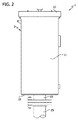
次に図面、特に図1、2および6を参照すると、本発明の繊維層ミスト除去装置1は、長方形断面を有する内部空間5を画定するハウジング3を備えることを示している(参照番号は、一般にその対象を示す)。一実施形態において、内部空間5は、比較的限定され、14インチ(36cm)×14インチ(36cm)×36インチ(91cm)の容積を有する。ハウジング3は、左右の側壁7、9、前後の壁11、13、底部壁15および頂部壁17を含む。ミスト除去装置1は、図1および図2の方向で、便宜上説明される。他の方向が本発明の範囲内で使われてもよいことが理解できるであろう。導入管19は、底部壁15の開口部21を通って、ハウジング3の内部空間5と流体連通する。導入管19は、液体エーロゾルを含んだ気体流が生じる何らかの機械または工程(図示せず)から延びた流入管23と接続をする。例えば、流入管23は、大量のタービン軸受潤滑剤(すなわち、オイル)を排出する航空転用型タービン潤滑油排気口から、流出流を運んでもよい。ハウジング3の頂部壁17は、ハウジングの導出口を形成する一対の溝25を含む(図1および7参照)。頂部壁17を覆う(しかし、上方で間隔が置かれる)キャップ27は、ハウジング3内に異物を入れないように援助し、導出溝25から流出流を拡散しない(図2参照)。ハウジングが本発明の要旨を逸脱しない範囲で他の構成を有してもよいことはいうまでもない。ハウジングの大きさは説明されたものと異なってもよいが、ろ過の必要のある気体の流れに対して小さい空間で使用するための特定用途を本発明が有することに注意すべきである。
Referring now to the drawings, in particular FIGS. 1, 2 and 6, the fiber layer mist removal device 1 of the present invention is shown to comprise a
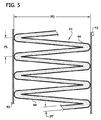
ハウジング3は、向かい合った板状の表面網43の間にひだ状繊維マット41を支持した長方形フレーム39を各々が備える4枚のフィルタ板(31、33、35および37で一般に示される)を含む(図4参照)。板状の表面網43は、一実施形態においては、約0.011インチ(0.28mm)の直径を有するワイヤで作られたステンレス鋼18×18メッシュである。図の実施形態では、ひだ状繊維マット41は、支持網44の間に圧縮された繊維素材を備える。フレーム39はステンレス鋼の溝から成り、ひだ状マット41がポリウレタンまたは他の適切な注封材料(図示せず)で溝に封止される。フィルタ板の枚数は本発明の範囲内で4枚以外でもよいことが理解できるであろう。3枚のフィルタ板(31、33、35)のフレーム39の1つの表面は、フレーム表面の3つの側に沿って延びたガスケット45を有する。第4の側面は、以下に、より詳細に説明される理由のため、開いたままとされる。ひだ状繊維マット41は、適切な繊維状物質から形成することができ、気体流の液負荷のために必要とされる特性を有することができる。例えば、適切な繊維マットは、適切な繊維バインダーおよび繊維処理剤若しくは繊維仕上げ剤を有する高分子繊維あるいはガラス繊維から製造できるものであってよい。一実施形態においては、繊維マット41は、デンバー(コロラド州)のジョンズ・マンビル社製の米国で利用可能な繊維マットLF ― 4 1/2インチである。繊維マットLF ― 4 1/2インチは、約1から10ミクロン(1000分の0.04から1000分の0.4インチ)の平均径を有する繊維、より好ましくは、1から5ミクロン(1000分の0.04から1000分の0.20インチ)の間の平均径を有する繊維により形成される。繊維マットは、約1/2インチ(12.7mm)の非圧縮時の厚さ、約0.40oz/ft2(121.6g/m2)のコンポジット重量を有する。約25FPM(0.13m/s)の速度を有する気流において、マット全体の呼び圧力損失は、約0.45インチwc(112Pa)である。フィルタ板31〜37に組み込まれるように、繊維マット41は、約0.1から0.53インチ(2.5から13mm)の圧縮時のひだ厚PT、および約1から12ポンド/ft3(16から192kg/m3)の圧縮密度を有する。好ましくは、ミスト除去装置圧力損失、および、所望の効率を達成するのに必要な総ろ過量を減少させるため、捕集された液体(例えば、オイル)がフィルタのより小さな領域をふさぐように、繊維は、撥油性または撥水性であるように処理される。図3および5に最も良く示されているように、繊維マット41は、ミスト捕集に利用できる表面積を増加させるために、ひだをつけられる。表面積は、ひだ深さPDおよびひだ間隔PSを変化させることにより、最大となる。ひだ深さPDは、好ましくは約1から4インチ(2.5から10cm)の範囲、より好ましくは約2から3インチ(5から7.5cm)の範囲となる。ひだ間隔PSは、好ましくは1インチにつき約0.5本から3本のひだ(1cmにつき0.2本から1.2本のひだ)の範囲、より好ましくは1インチにつき約2本から2.5本のひだ(1cmにつき0.75本から1本のひだ)の範囲となる。気体流がろ材を詰まらせる傾向のある微粒子または液体(「閉塞物質」)を含む場合、より粗いプレフィルタマット(図示せず)をフィルタ板の上流面上に組み込むことができる。また、入って来る気体流のミスト負荷が高い場合、捕集された液体の再飛散を抑制するため、中央フィルタ板の下流面に排水層(図示せず)を追加できる。フィルタ板が本発明の範囲内で他の構造を有してもよいことを理解すべきである。例えば、板状の表面網43は、省略されてもよい。
The
ハウジング3の内部は、フィルタ板31〜37が各々間隔を置かれた関係で取り付けられるように構成される。フィルタ板31〜37は、長方形で、縦が(ハウジングの最大寸法である)ハウジング3の高さに沿って広がるように配置される。図6を参照すると、ミスト除去装置1は、更に、底部壁15に隣接して、ハウジング3内に孤立した板49を含むが、底部壁と孤立した板の間のハウジングの内部空間5に気体流が入ることができるように、壁上に間隔が置かれる。孤立した板49は、中央導入溝51および2つの側面凹所53、55を含む。フィルタ板31〜37への流れは、中央導入溝51または側面凹所53、55のどちらかを通過する。孤立した板49はタブ57(2つだけが図示される)を備え、ハウジング3はタブ59(4つだけが図示される)を備え、これらのタブはフィルタ板のフレーム39と係合して、隣接するフィルタ板31〜37を各々から間隔を置いて配置するか、左右のフィルタ板31、37をハウジングの左右の側壁7、9から(それぞれ)間隔を置いて配置する。図6では、フィルタ板31〜37の断片的な部分が二点鎖線で示され、そして、底部壁15の導入開口部21を示すために孤立した板49が一部切断されている。付加的なタブ(図示せず)が、ハウジング3の前壁11および孤立した板49の正面に提供されてもよい。この間隔が、隣接するフィルタ板の間、および、外側の2枚のフィルタ板とハウジング3の側壁の間に、(それぞれ61、63、65、67および69で示される)5つの流路をフィルタ板31〜37に画定する。
The interior of the
フィルタ板35のガスケット45(図4参照)は、ハウジング3の右側のフィルタ板37のフレーム39の内面と係合する。ガスケット45は、内面で間隔および封止を維持するのを援助し、更に、右側のフィルタ板37と、右側のフィルタ板に直接隣接した中央のフィルタ板35の間の空間への、導入開口部21からの気体の侵入を防止するのを援助する。ポリウレタンのようなシール材/接着剤が、強力な封止を形成するために、ガスケット45およびフレーム39の内面に適用される。更に、両方のフィルタ板35、37のフレーム39両方は、ポリウレタンまたは他の適切なシール材を使用して、共に、ハウジング3内部で頂部壁17に封止される。図示の実施形態では、フィルタ板35、37は、左側の壁、右側の壁、前壁および後壁7、9、11、13に、または、孤立した板49に封止されない。気体が迂回するのを妨げる他の適切な封止装置が、本発明の範囲内で使用されてもよい。孤立した板49の右側の凹所55は、右側のフィルタ板37とハウジング3の右側の壁13の間に画定された流路69に通じる。しかし、流路69は、ハウジング3の頂部壁17とフィルタ板37の封止接続によって、上端部でふさがれる。2枚の中央のフィルタ板35、33は、底部壁15で互いに封止されず、孤立した板49の導入溝51に通じる。しかし、中央のフィルタ板33、35間の流路65は、頂部壁17とフィルタ板の封止接続によって、上端部でふさがれる。左側の壁7に隣接したフィルタ板31、および、左側のフィルタ板に隣接した中央のフィルタ板33が、既に説明をした右側のフィルタ板37、および、隣接した中央のフィルタ板35と同じ構成を有することはいうまでもない。
The gasket 45 (see FIG. 4) of the
ハウジング3に入る気体流は、底部壁15と孤立した板49の間のプレナム73を通過し、3つのフロー流に分けられる。1つのフロー流は、矢印75によって示されるように、中央のフィルタ板33、35の間の流路65へと、孤立した板49の導入溝51を通過する。頂部壁17に流路65の出口がないため、中央のフィルタ板33、35を通る矢印77によって示されるように、気体フロー流は、分割されて横へと押しやられ、中央のフィルタ板によって、エーロゾル(例えば、オイル)が気体流からろ過され、そして、導出溝25と流体連通する流路63、67に入る。他の2つの流れは、矢印79および81によって示されるように、左右のフィルタ板31、37とハウジング3の左右の壁7、9(それぞれ)の間の、孤立した板49の凹所53、55を貫流する。左右のフィルタ板31、37と、対応する左右の壁7、9の間の、流路61、69に入る流れ79、81は、上板17とフィルタ板の封止接続によって、同じように遮断される。気体は、エーロゾルがろ過できるように、矢印83、85によって示されるように、フィルタ板31、37の繊維マット41の内部へ強制的に貫流される。側面の流れ83、85は、導出溝25に接続した流路63、67に入る。ひだ速度(すなわち、繊維マット41の層を横切る流体の速度)は、比較的遅い。
The gas stream entering the
一実施例においては、タービン潤滑油軸受排気が、ミスト除去装置1に流入管23によって運ばれる。この例では、ハウジング3の容積は、幅14インチ(36cm)×奥行き14インチ(36cm)×高さ36インチ(91cm)であった。エーロゾルの補集に利用できるフィルタ板31、33、35、37の、繊維マット41の総露出表面積は、154ft2(14m2)であった。ミスト除去装置1全体の圧力損失は、約50ft3/分(0.02m3/分)の流速で、0.5インチwc(125Pa)未満であった。ミスト除去装置1の除去効率は、約500mg/m3の導入口ミスト負荷を基準として、99.5%であった。放出が約1から2ppmwのタービン油ミストだけであることが予想される。より一般的には、気体流をろ過するために使用されるフィルタ板の領域の、容器の容積に対する比率は、好ましくは、約20ft2/ft3(66m2/m3)から約36ft2/ft3(118m2/m3)となる。
In one embodiment, turbine lubricant bearing exhaust is carried to the mist remover 1 by an
本発明またはその好ましい実施形態の要素を導くとき、冠詞「a」「an」「the」および「said」は、1つ以上の要素があることを意味するものとする。用語「備える」、「含む」および「有する」は包括的で、記載された要素以外の追加的要素があってもよいことを意味するものとする。更に、「up」、「down」、「inner」、「outer」および他の配向用語が便宜上使用されるが、構成要素の何らかの特定の方向を要求するものではない。 In deriving elements of the present invention or preferred embodiments thereof, the articles “a”, “an”, “the” and “said” shall mean that there are one or more elements. The terms “comprising”, “including” and “having” are intended to be inclusive and mean that there may be additional elements other than the listed elements. Furthermore, “up”, “down”, “inner”, “outer” and other orientation terms are used for convenience but do not require any particular orientation of the component.
上記より、本発明のいくつかの目的が達成され、他の有利な結果がもたらされたことを理解するであろう。 In view of the above, it will be seen that the several objects of the invention are achieved and other advantageous results attained.
本発明の範囲内においてさまざまな変更を上記の構造にもたらすことができ、上記および添付図面に示されたすべての事項は、例示的、非限定的に解釈されるものとする。 Various modifications may be made to the above structure within the scope of the present invention, and all matters described above and shown in the accompanying drawings are to be interpreted in an illustrative and non-limiting manner.
Claims (18)
容器の流入端部に導入口および容器の流出端部に導出口を有する容器と、
微細繊維により形成された繊維ろ材を有する繊維マットを各々含むフィルタ板と、
を備え、
前記繊維マットが前記フィルタ板の縦方向に延びるひだを有し、前記フィルタ板が隣接するフィルタ板の前記フィルタマットが離れて間隔を置くように前記容器に配置され、隣接するフィルタ板の間の流路およびフィルタ板と前記容器の隣接する壁の間の流路を画定し、前記流路のいくつかが前記導入口と流体連通する導入流路を画定し、気体流が前記導入流路から前記導出口へ出るのを防止するため、前記容器の前記流出端部でふさがれ、かつ、前記流路のいくつかが前記導出口と流体連通する導出流路を画定し、前記導入口を通って前記容器へ入った気体流が前記導出流路へ入るのを防止するため、前記容器の前記流入端部でふさがれており、
前記気体流が、前記容器へと入り、前記導入流路へと移ってから、前記導入流の方向に対して横に前記フィルタ板の1つを通過して、前記容器の前記導出口への通路である前記導出流路へと移る、
ミスト除去装置。 A mist remover used to separate an aerosol from a gas stream,
A container having an inlet at the inlet end of the container and an outlet at the outlet end of the container;
Filter plates each including a fiber mat having a fiber filter medium formed of fine fibers;
With
The fiber mat has pleats extending in the longitudinal direction of the filter plate, and the filter plate is disposed in the container so that the filter mats of adjacent filter plates are spaced apart from each other, and a flow path between adjacent filter plates And a flow path between the filter plate and the adjacent wall of the container, some of the flow paths defining an introduction flow path in fluid communication with the inlet, and a gas flow from the introduction flow path. In order to prevent exit to the outlet, the outlet end of the container is blocked and some of the channels define an outlet channel in fluid communication with the outlet, and through the inlet port the In order to prevent the gas flow entering the container from entering the outlet channel, the container is blocked at the inflow end of the container,
After the gas flow enters the container and moves to the introduction flow path, it passes through one of the filter plates laterally with respect to the direction of the introduction flow to the outlet of the container. Move to the outlet channel which is a passage,
Mist removal device.
容器の流入端部に導入口および容器の流出端部に導出口を有する容器と、
繊維ろ材を有する繊維マットを各々含むフィルタ板と、
を備え、
前記繊維マットがひだを有し、前記フィルタ板が隣接するフィルタ板のフィルタマットが離れて間隔を置くように前記容器に配置され、流路を画定し、前記流路のうちの少なくとも1つが前記導入口と流体連通する導入流路を画定し、気体流が前記導入流路から前記導出口へ出るのを防止するために、前記容器の前記流出端部でふさがれ、かつ、前記流路のうちの少なくとも1つが前記導出口と流体連通する導出流路を画定し、前記導入口を通って前記容器へ入った気体流が前記導出流路へ入るのを防止するために、前記容器の前記流入端部でふさがれており、
前記気体流が、前記容器へと入り、前記導入流の方向に対して横に前記フィルタ板のうちの少なくとも1つを通過して、前記容器の前記導出口への通路である導出流路へと移る、
ミスト除去装置。 A mist remover used to separate an aerosol from a gas stream,
A container having an inlet at the inlet end of the container and an outlet at the outlet end of the container;
Filter plates each including a fiber mat having a fiber filter medium;
With
The fiber mat has pleats, and the filter plate is disposed in the container such that the filter mats of adjacent filter plates are spaced apart to define a flow path, at least one of the flow paths being the Defining an inlet flow path in fluid communication with the inlet and blocking the flow of gas from the inlet flow path to the outlet outlet at the outlet end of the container; At least one of which defines a lead-out channel in fluid communication with the lead-out port and prevents gas flow entering the container through the inlet port from entering the lead-out channel. Blocked at the inflow end,
The gas flow enters the container, passes through at least one of the filter plates laterally with respect to the direction of the introduction flow, and leads to a discharge channel that is a passage to the discharge port of the container. Move on,
Mist removal device.
Applications Claiming Priority (3)
| Application Number | Priority Date | Filing Date | Title |
|---|---|---|---|
| US10944708P | 2008-10-29 | 2008-10-29 | |
| US61/109,447 | 2008-10-29 | ||
| PCT/US2009/054281 WO2010051091A1 (en) | 2008-10-29 | 2009-08-19 | Compact fiber bed mist eliminator |
Publications (1)
| Publication Number | Publication Date |
|---|---|
| JP2012507392A true JP2012507392A (en) | 2012-03-29 |
Family
ID=41128005
Family Applications (1)
| Application Number | Title | Priority Date | Filing Date |
|---|---|---|---|
| JP2011534552A Pending JP2012507392A (en) | 2008-10-29 | 2009-08-19 | Small fiber layer mist removal device |
Country Status (12)
| Country | Link |
|---|---|
| US (1) | US20110023428A1 (en) |
| EP (1) | EP2365854A1 (en) |
| JP (1) | JP2012507392A (en) |
| KR (1) | KR20110097762A (en) |
| CN (1) | CN102215933A (en) |
| AP (1) | AP2011005709A0 (en) |
| AU (1) | AU2009310316A1 (en) |
| MA (1) | MA32732B1 (en) |
| RU (1) | RU2011121607A (en) |
| TN (1) | TN2011000183A1 (en) |
| WO (1) | WO2010051091A1 (en) |
| ZA (1) | ZA201103093B (en) |
Cited By (2)
| Publication number | Priority date | Publication date | Assignee | Title |
|---|---|---|---|---|
| JP2017530863A (en) * | 2014-10-10 | 2017-10-19 | インテグリス・インコーポレーテッド | Use or dispensing points for filters with multiple pleat packs |
| JP2018069152A (en) * | 2016-10-28 | 2018-05-10 | 日進技研株式会社 | Filter device for air cleaning |
Families Citing this family (15)
| Publication number | Priority date | Publication date | Assignee | Title |
|---|---|---|---|---|
| KR101566725B1 (en) | 2011-09-27 | 2015-11-09 | 현대자동차 주식회사 | Hydraulic clutch |
| US9269998B2 (en) | 2013-03-13 | 2016-02-23 | Fluidic, Inc. | Concave gas vent for electrochemical cell |
| US9325037B2 (en) | 2013-03-13 | 2016-04-26 | Fluidic, Inc. | Hetero-ionic aromatic additives for electrochemical cells comprising a metal fuel |
| CN105617771A (en) * | 2014-10-29 | 2016-06-01 | 世源科技工程有限公司 | Air filter, air filtration unit and air filtration system |
| WO2016172101A1 (en) | 2015-04-21 | 2016-10-27 | Donaldson Company, Inc. | Filter assembly and methods |
| CN109478643B (en) | 2016-07-22 | 2022-03-15 | 南特能源公司 | Moisture and carbon dioxide management systems in electrochemical cells |
| MX2019000905A (en) | 2016-07-22 | 2019-10-02 | Nantenergy Inc | Mist elimination system for electrochemical cells. |
| CN106310826A (en) * | 2016-10-14 | 2017-01-11 | 徐州工程学院 | High-efficiency air purification device in garbage disposal system and operating method thereof |
| CN119481486A (en) | 2018-06-29 | 2025-02-18 | 福恩能源公司 | Rolling diaphragm seal |
| CN120184457A (en) | 2018-06-29 | 2025-06-20 | 福恩能源公司 | Metal-air electrochemical cell architecture |
| SE543277C2 (en) | 2019-03-14 | 2020-11-10 | Camfil Ab | Aerosol distribution in filter testing systems |
| WO2020264344A1 (en) | 2019-06-28 | 2020-12-30 | Form Energy Inc. | Device architectures for metal-air batteries |
| US11007547B1 (en) * | 2019-08-08 | 2021-05-18 | Instant Auto Body | Portable paint booth |
| EP4147296A4 (en) | 2020-05-06 | 2025-08-13 | Form Energy Inc | ELECTROCHEMICAL ENERGY STORAGE SYSTEM WITH DECOUPLED ELECTRODE |
| EP4282508A1 (en) * | 2022-05-23 | 2023-11-29 | Mann+Hummel Life Sciences & Environment Holding Singapore Pte. Ltd. | Melamine-based foam filter medium |
Family Cites Families (22)
| Publication number | Priority date | Publication date | Assignee | Title |
|---|---|---|---|---|
| GB1392936A (en) * | 1972-04-12 | 1975-05-07 | Shoketsu Kinzoku Kogyo Kk | Mist separator |
| US4443233A (en) * | 1982-08-27 | 1984-04-17 | Monsanto Company | Mist separator |
| US5470364A (en) * | 1992-01-07 | 1995-11-28 | Pall Corporation | Regenerable diesel exhaust filter |
| US5454845A (en) * | 1992-09-25 | 1995-10-03 | Kabushiki Kaisha Toyoda Jidoshokki Seisakusho | Heat-resistant filter |
| US5346519A (en) * | 1993-04-27 | 1994-09-13 | Pneumafil Corporation | Filter media construction |
| US5682740A (en) * | 1995-05-12 | 1997-11-04 | Isuzu Ceramics Research Institute Co., Ltd. | Diesel particulate filter apparatus |
| US5820646A (en) * | 1996-04-26 | 1998-10-13 | Donaldson Company, Inc. | Inline filter apparatus |
| US6056796A (en) * | 1998-02-09 | 2000-05-02 | The United States Of America As Represented By The United States Department Of Energy | Rigid porous filter |
| US6123751A (en) * | 1998-06-09 | 2000-09-26 | Donaldson Company, Inc. | Filter construction resistant to the passage of water soluble materials; and method |
| US6059851A (en) * | 1998-09-03 | 2000-05-09 | Donaldson Company, Inc. | Air cleaner; method and use |
| US6203592B1 (en) * | 1999-04-20 | 2001-03-20 | Dana Corporation | Filter media configuration |
| US6290739B1 (en) * | 1999-12-29 | 2001-09-18 | Donaldson Company, Inc. | Aerosol separator; and method |
| US6673136B2 (en) * | 2000-09-05 | 2004-01-06 | Donaldson Company, Inc. | Air filtration arrangements having fluted media constructions and methods |
| US7115150B2 (en) * | 2000-09-05 | 2006-10-03 | Donaldson Company, Inc. | Mist filtration arrangement utilizing fine fiber layer in contact with media having a pleated construction and floor filter method |
| US7255723B2 (en) * | 2004-01-09 | 2007-08-14 | Aaf Mcquay, Inc. | Crest supported filter frame assembly and method |
| US7896940B2 (en) * | 2004-07-09 | 2011-03-01 | 3M Innovative Properties Company | Self-supporting pleated filter media |
| US7323105B1 (en) * | 2004-08-11 | 2008-01-29 | Fleetguard, Inc. | High capacity direct flow filter with maintained channel width |
| US7323106B2 (en) * | 2005-09-01 | 2008-01-29 | Fleetguard, Inc. | Multi-element filter with multiple pleat channel height |
| US7582130B2 (en) * | 2006-04-14 | 2009-09-01 | Cummins Filtration Ip Inc. | Coalescing filter assembly |
| US20080092501A1 (en) * | 2006-02-16 | 2008-04-24 | Sporre Timothy D | Polygonal filter element with radiused corners, assemblies, and methods for filtering |
| US7753981B2 (en) * | 2006-10-19 | 2010-07-13 | Nitto Denko Corporation | Filter unit and filter unit panel |
| US7785384B2 (en) * | 2007-01-09 | 2010-08-31 | Honeywell International Inc. | Pleated diesel particulate filter assembly |
-
2009
- 2009-08-19 WO PCT/US2009/054281 patent/WO2010051091A1/en not_active Ceased
- 2009-08-19 RU RU2011121607/05A patent/RU2011121607A/en unknown
- 2009-08-19 US US12/543,901 patent/US20110023428A1/en not_active Abandoned
- 2009-08-19 CN CN200980143172.1A patent/CN102215933A/en active Pending
- 2009-08-19 EP EP09791660A patent/EP2365854A1/en not_active Withdrawn
- 2009-08-19 AP AP2011005709A patent/AP2011005709A0/en unknown
- 2009-08-19 KR KR1020117009673A patent/KR20110097762A/en not_active Withdrawn
- 2009-08-19 AU AU2009310316A patent/AU2009310316A1/en not_active Abandoned
- 2009-08-19 JP JP2011534552A patent/JP2012507392A/en active Pending
-
2011
- 2011-04-19 TN TN2011000183A patent/TN2011000183A1/en unknown
- 2011-04-26 ZA ZA2011/03093A patent/ZA201103093B/en unknown
- 2011-04-29 MA MA33799A patent/MA32732B1/en unknown
Cited By (2)
| Publication number | Priority date | Publication date | Assignee | Title |
|---|---|---|---|---|
| JP2017530863A (en) * | 2014-10-10 | 2017-10-19 | インテグリス・インコーポレーテッド | Use or dispensing points for filters with multiple pleat packs |
| JP2018069152A (en) * | 2016-10-28 | 2018-05-10 | 日進技研株式会社 | Filter device for air cleaning |
Also Published As
| Publication number | Publication date |
|---|---|
| KR20110097762A (en) | 2011-08-31 |
| EP2365854A1 (en) | 2011-09-21 |
| ZA201103093B (en) | 2012-09-26 |
| CN102215933A (en) | 2011-10-12 |
| TN2011000183A1 (en) | 2012-12-17 |
| US20110023428A1 (en) | 2011-02-03 |
| WO2010051091A1 (en) | 2010-05-06 |
| RU2011121607A (en) | 2012-12-10 |
| MA32732B1 (en) | 2011-10-02 |
| AU2009310316A1 (en) | 2010-05-06 |
| AP2011005709A0 (en) | 2011-06-30 |
Similar Documents
| Publication | Publication Date | Title |
|---|---|---|
| JP2012507392A (en) | Small fiber layer mist removal device | |
| US7041159B2 (en) | Separation apparatus | |
| US20080035103A1 (en) | Crankcase Ventilation Filter | |
| CN101421017B (en) | Fiber bed assembly and fiber bed for the fiber bed assembly | |
| EP1858618B1 (en) | Aerosol separator | |
| EP2414068B1 (en) | Filter assembly for gas turbine with mounting flange extension | |
| US6852148B2 (en) | Aerosol separator and method | |
| JP5592471B2 (en) | Filter cassette, filter arrangement structure and gas turbine equipped with such a filter cassette | |
| CN102614722A (en) | Gas filter assemblies and methods for filtering gases | |
| CN102281935B (en) | Combined filter | |
| EA011777B1 (en) | A filter and a system of crankcase ventilation | |
| KR20080056662A (en) | Moisture Removal Device and Method | |
| JP2002520135A (en) | Mist collector and method | |
| AU2014236577A1 (en) | Rectangular stacked fluted filter cartridge | |
| JP4093568B2 (en) | Especially filter elements that separate liquids from gas streams | |
| US7708794B2 (en) | Separator made of a fibrous porous material such as a felt | |
| JP2019510629A (en) | Filter element for filtering fluid passing through the filter element, coalescer filter, compressed air filter system, use of the filter element, and method of manufacturing the coalescer filter | |
| US20130192180A1 (en) | Filter assembly | |
| WO2005082488A2 (en) | Arrangement for separating an aerosol from a gas stream | |
| JPH0636843B2 (en) | Filter device | |
| JP2013078747A (en) | Dust collector | |
| CN117651599A (en) | Filter elements, cartridges and filter systems | |
| US11752462B2 (en) | Effluent processing apparatus and method for a vehicle air brake charging system | |
| CN112055779B (en) | Engine air cleaner with integrated compressor inhibitor | |
| JP7249028B2 (en) | air filter |