JP2012508531A - Method and apparatus for enabling and disabling auxiliary downlink carriers - Google Patents
Method and apparatus for enabling and disabling auxiliary downlink carriers Download PDFInfo
- Publication number
- JP2012508531A JP2012508531A JP2011535764A JP2011535764A JP2012508531A JP 2012508531 A JP2012508531 A JP 2012508531A JP 2011535764 A JP2011535764 A JP 2011535764A JP 2011535764 A JP2011535764 A JP 2011535764A JP 2012508531 A JP2012508531 A JP 2012508531A
- Authority
- JP
- Japan
- Prior art keywords
- wtru
- secondary serving
- serving cell
- cell
- dsch
- Prior art date
- Legal status (The legal status is an assumption and is not a legal conclusion. Google has not performed a legal analysis and makes no representation as to the accuracy of the status listed.)
- Granted
Links
Images




Classifications
-
- H—ELECTRICITY
- H04—ELECTRIC COMMUNICATION TECHNIQUE
- H04W—WIRELESS COMMUNICATION NETWORKS
- H04W72/00—Local resource management
- H04W72/20—Control channels or signalling for resource management
- H04W72/23—Control channels or signalling for resource management in the downlink direction of a wireless link, i.e. towards a terminal
- H04W72/232—Control channels or signalling for resource management in the downlink direction of a wireless link, i.e. towards a terminal the control data signalling from the physical layer, e.g. DCI signalling
-
- H—ELECTRICITY
- H04—ELECTRIC COMMUNICATION TECHNIQUE
- H04L—TRANSMISSION OF DIGITAL INFORMATION, e.g. TELEGRAPHIC COMMUNICATION
- H04L1/00—Arrangements for detecting or preventing errors in the information received
- H04L1/12—Arrangements for detecting or preventing errors in the information received by using return channel
- H04L1/16—Arrangements for detecting or preventing errors in the information received by using return channel in which the return channel carries supervisory signals, e.g. repetition request signals
- H04L1/18—Automatic repetition systems, e.g. Van Duuren systems
- H04L1/1812—Hybrid protocols; Hybrid automatic repeat request [HARQ]
-
- H—ELECTRICITY
- H04—ELECTRIC COMMUNICATION TECHNIQUE
- H04L—TRANSMISSION OF DIGITAL INFORMATION, e.g. TELEGRAPHIC COMMUNICATION
- H04L1/00—Arrangements for detecting or preventing errors in the information received
- H04L1/12—Arrangements for detecting or preventing errors in the information received by using return channel
- H04L1/16—Arrangements for detecting or preventing errors in the information received by using return channel in which the return channel carries supervisory signals, e.g. repetition request signals
- H04L1/18—Automatic repetition systems, e.g. Van Duuren systems
- H04L1/1822—Automatic repetition systems, e.g. Van Duuren systems involving configuration of automatic repeat request [ARQ] with parallel processes
-
- H—ELECTRICITY
- H04—ELECTRIC COMMUNICATION TECHNIQUE
- H04L—TRANSMISSION OF DIGITAL INFORMATION, e.g. TELEGRAPHIC COMMUNICATION
- H04L1/00—Arrangements for detecting or preventing errors in the information received
- H04L1/12—Arrangements for detecting or preventing errors in the information received by using return channel
- H04L1/16—Arrangements for detecting or preventing errors in the information received by using return channel in which the return channel carries supervisory signals, e.g. repetition request signals
- H04L1/18—Automatic repetition systems, e.g. Van Duuren systems
- H04L1/1829—Arrangements specially adapted for the receiver end
- H04L1/1835—Buffer management
-
- H—ELECTRICITY
- H04—ELECTRIC COMMUNICATION TECHNIQUE
- H04L—TRANSMISSION OF DIGITAL INFORMATION, e.g. TELEGRAPHIC COMMUNICATION
- H04L5/00—Arrangements affording multiple use of the transmission path
- H04L5/0091—Signalling for the administration of the divided path, e.g. signalling of configuration information
- H04L5/0096—Indication of changes in allocation
- H04L5/0098—Signalling of the activation or deactivation of component carriers, subcarriers or frequency bands
-
- H—ELECTRICITY
- H04—ELECTRIC COMMUNICATION TECHNIQUE
- H04W—WIRELESS COMMUNICATION NETWORKS
- H04W52/00—Power management, e.g. Transmission Power Control [TPC] or power classes
- H04W52/02—Power saving arrangements
- H04W52/0209—Power saving arrangements in terminal devices
- H04W52/0212—Power saving arrangements in terminal devices managed by the network, e.g. network or access point is leader and terminal is follower
- H04W52/0216—Power saving arrangements in terminal devices managed by the network, e.g. network or access point is leader and terminal is follower using a pre-established activity schedule, e.g. traffic indication frame
-
- H—ELECTRICITY
- H04—ELECTRIC COMMUNICATION TECHNIQUE
- H04W—WIRELESS COMMUNICATION NETWORKS
- H04W72/00—Local resource management
- H04W72/20—Control channels or signalling for resource management
- H04W72/23—Control channels or signalling for resource management in the downlink direction of a wireless link, i.e. towards a terminal
-
- H—ELECTRICITY
- H04—ELECTRIC COMMUNICATION TECHNIQUE
- H04W—WIRELESS COMMUNICATION NETWORKS
- H04W76/00—Connection management
- H04W76/20—Manipulation of established connections
- H04W76/27—Transitions between radio resource control [RRC] states
-
- H—ELECTRICITY
- H04—ELECTRIC COMMUNICATION TECHNIQUE
- H04W—WIRELESS COMMUNICATION NETWORKS
- H04W76/00—Connection management
- H04W76/30—Connection release
- H04W76/34—Selective release of ongoing connections
-
- H—ELECTRICITY
- H04—ELECTRIC COMMUNICATION TECHNIQUE
- H04W—WIRELESS COMMUNICATION NETWORKS
- H04W88/00—Devices specially adapted for wireless communication networks, e.g. terminals, base stations or access point devices
- H04W88/02—Terminal devices
-
- Y—GENERAL TAGGING OF NEW TECHNOLOGICAL DEVELOPMENTS; GENERAL TAGGING OF CROSS-SECTIONAL TECHNOLOGIES SPANNING OVER SEVERAL SECTIONS OF THE IPC; TECHNICAL SUBJECTS COVERED BY FORMER USPC CROSS-REFERENCE ART COLLECTIONS [XRACs] AND DIGESTS
- Y02—TECHNOLOGIES OR APPLICATIONS FOR MITIGATION OR ADAPTATION AGAINST CLIMATE CHANGE
- Y02B—CLIMATE CHANGE MITIGATION TECHNOLOGIES RELATED TO BUILDINGS, e.g. HOUSING, HOUSE APPLIANCES OR RELATED END-USER APPLICATIONS
- Y02B70/00—Technologies for an efficient end-user side electric power management and consumption
- Y02B70/30—Systems integrating technologies related to power network operation and communication or information technologies for improving the carbon footprint of the management of residential or tertiary loads, i.e. smart grids as climate change mitigation technology in the buildings sector, including also the last stages of power distribution and the control, monitoring or operating management systems at local level
-
- Y—GENERAL TAGGING OF NEW TECHNOLOGICAL DEVELOPMENTS; GENERAL TAGGING OF CROSS-SECTIONAL TECHNOLOGIES SPANNING OVER SEVERAL SECTIONS OF THE IPC; TECHNICAL SUBJECTS COVERED BY FORMER USPC CROSS-REFERENCE ART COLLECTIONS [XRACs] AND DIGESTS
- Y02—TECHNOLOGIES OR APPLICATIONS FOR MITIGATION OR ADAPTATION AGAINST CLIMATE CHANGE
- Y02D—CLIMATE CHANGE MITIGATION TECHNOLOGIES IN INFORMATION AND COMMUNICATION TECHNOLOGIES [ICT], I.E. INFORMATION AND COMMUNICATION TECHNOLOGIES AIMING AT THE REDUCTION OF THEIR OWN ENERGY USE
- Y02D30/00—Reducing energy consumption in communication networks
- Y02D30/70—Reducing energy consumption in communication networks in wireless communication networks
Landscapes
- Engineering & Computer Science (AREA)
- Signal Processing (AREA)
- Computer Networks & Wireless Communication (AREA)
- Mobile Radio Communication Systems (AREA)
Abstract
二次サービングセルの状態を判定するマルチ・セル無線通信のための方法および装置が開示される。二次サービングセルが無効であるという条件にて、二次サービングセルに関連付けられたHARQ(Hybrid Repeat Request)処理が公開される。A method and apparatus for multi-cell wireless communication for determining the status of a secondary serving cell is disclosed. A HARQ (Hybrid Repeat Request) process associated with the secondary serving cell is disclosed under the condition that the secondary serving cell is invalid.
Description
この出願は無線通信に関する。 This application relates to wireless communications.
本出願は、2008年11月10日に出願された、米国仮出願番号第61/113,149号に基づく優先権を主張し、この番号を参照することにより、そのすべての開示内容を本明細書の一部とする。 This application claims priority based on US Provisional Application No. 61 / 113,149, filed on November 10, 2008, the entire disclosure of which is incorporated herein by reference. Part of the book.
無線通信システムは、データ・ネットワークへの連続的なそしてより高速なアクセスを提供する必要性を満たすために発展している。これらの必要性を満たすために、無線通信システムはデータの送信のために複数のキャリアを使用することができる。データの送信のために複数のキャリアを使用する無線通信システムは、マルチ・キャリア・システムと呼ぶことができる。複数のキャリアの使用は、セル方式のおよび非セル方式の両方の無線システムにおいて拡大している。 Wireless communication systems are evolving to meet the need to provide continuous and faster access to data networks. To meet these needs, wireless communication systems can use multiple carriers for data transmission. A wireless communication system that uses multiple carriers for data transmission may be referred to as a multi-carrier system. The use of multiple carriers is expanding in both cellular and non-cell wireless systems.
マルチ・キャリア・システムは、無線通信システムにおいて利用可能な帯域幅を、どれだけのキャリアが利用可能となるかの倍数にしたがって、増加させることができる。例えば、2キャリア・システムは、単一のキャリア・システムに比較して、帯域幅を2倍にすることができ、3キャリア・システムは、単一のキャリア・システムに比較して、帯域幅を3倍にすることができる、等である。 Multi-carrier systems can increase the bandwidth available in a wireless communication system according to a multiple of how many carriers are available. For example, a two carrier system can double the bandwidth compared to a single carrier system, and a three carrier system can increase bandwidth compared to a single carrier system. Can be tripled, etc.
このスループットの利得に加えて、ダイバーシティおよびジョイント(joint)・スケジューリングの利得も期待することができる。このことにより、エンド・ユーザーに対するQoS(サービス品質)の改良をもたらすことができる。さらに複数のキャリアの使用は、MIMO(Multiple-Input Multiple-Output)と組み合わせて使用することができる。 In addition to this throughput gain, diversity and joint scheduling gains can also be expected. This can lead to improved quality of service (QoS) for end users. Furthermore, the use of a plurality of carriers can be used in combination with MIMO (Multiple-Input Multiple-Output).
例として、3GPP(第3世代パートナーシッププロジェクト)システムの環境においては、3GPP仕様のリリース8においてDC−HSDPA(Dual Cell High Speed Downlink Packet Access)と呼ばれる新機能を導入している。DC−HSDPAにより、基地局(通信ネットワークの他の変形または種別においては、ノードB、アクセス・ポイント、サイト制御装置などと呼ばれる場合もある)は、1つのWTRU(Wireless Transmit/Receive Unit:無線送受信ユニット)に対して、同時に2つの下りリンクのキャリアを通して通信する。これは、WTRUにとって利用可能な帯域幅および最高データ速度を2倍にするだけでなく、2つのキャリアを通しての高速のスケジューリングおよび高速のチャネル・フィードバックによってネットワーク効率を増加させる可能性も有する。 As an example, in a 3GPP (third generation partnership project) system environment, a new function called DC-HSDPA (Dual Cell High Speed Downlink Packet Access) is introduced in Release 8 of the 3GPP specifications. With DC-HSDPA, a base station (sometimes referred to as a Node B, an access point, a site controller, etc. in other variants or types of communication networks) allows one WTRU (Wireless Transmit / Receive Unit: wireless transmission / reception). Unit) through two downlink carriers at the same time. This not only doubles the available bandwidth and maximum data rate for the WTRU, but also has the potential to increase network efficiency through fast scheduling and fast channel feedback across the two carriers.
DC−HSDPA動作に対して、各WTRUには2つの下りリンク・キャリアが割り当てられる:すなわちアンカー・キャリアおよび補助(supplementary)キャリアである。アンカー・キャリアは、例えばHS−DSCH(High Speed Downlink Shared Channel)、E−DCH(Enhanced Dedicated Channel)、およびDCH(Dedicated Channel)オペレーションの、トランスポート・チャネルに関連付けられたすべての物理レイヤーの専用および共通の制御チャネルを伝達する。そのような物理レイヤーのチャネルには、例えばF−DPCH(Fractional Dedicated Physical Channel)、E−HICH(E-DCH HARQ Indicator Channel)、E−RGCH(E-DCH Relative Grant Channel)、E−AGCH(E-DCH Absolute Grant Channel)、CPICH(Common Pilot Channel)、HS-SCCH(High Speed Shared Control Channel)、およびHS−PDSCH(High Speed Physical Downlink Shared Channel)、ならびに同様のものが含まれる。補助キャリアは、WTRUに対してCPICH、HS−SCCH、およびHS−PDSCHを伝達することができる。現在のシステムにおいては、上りリンク送信は単一のキャリア上のままである。HS−DPCCH(High Speed Dedicated Physical Control Channel)フィードバック情報は、上りリンク・キャリア上にてノードBに提供され、そして各下りリンク・キャリアに対する情報を含む。 For DC-HSDPA operation, each WTRU is assigned two downlink carriers: an anchor carrier and a supplementary carrier. Anchor carriers are dedicated to all physical layers associated with the transport channel, eg, HS-DSCH (High Speed Downlink Shared Channel), E-DCH (Enhanced Dedicated Channel), and DCH (Dedicated Channel) operations. Communicate a common control channel. Such physical layer channels include, for example, F-DPCH (Fractional Dedicated Physical Channel), E-HICH (E-DCH HARQ Indicator Channel), E-RGCH (E-DCH Relative Grant Channel), E-AGCH (E -DCH Absolute Grant Channel), CPICH (Common Pilot Channel), HS-SCCH (High Speed Shared Control Channel), HS-PDSCH (High Speed Physical Downlink Shared Channel), and the like. The auxiliary carrier can carry CPICH, HS-SCCH, and HS-PDSCH to the WTRU. In current systems, the uplink transmission remains on a single carrier. HS-DPCCH (High Speed Dedicated Physical Control Channel) feedback information is provided to the Node B on the uplink carrier and includes information for each downlink carrier.
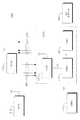
図1において、DC−HSDPAを実施する能力のあるWTRUのMAC(Medium Access Control)−ehsアーキテクチャが示される。図1に示されるように、MAC−ehsは2つのHARQエンティティを備える。DC−HSDPAにおいては、別のHARQエンティティをそれぞれのセルに割り当てることができる。したがって、分解および再順序化が、両方のセルに対して一緒に実行される。さらに、それぞれに対して別のH−RNTI(HS-DSCH Radio Network Transaction Identifier)を与えることができる。 In FIG. 1, a WTRU's Medium Access Control (MAC) -ehs architecture capable of implementing DC-HSDPA is shown. As shown in FIG. 1, MAC-ehs comprises two HARQ entities. In DC-HSDPA, another HARQ entity can be assigned to each cell. Therefore, decomposition and reordering are performed together for both cells. Further, different H-RNTI (HS-DSCH Radio Network Transaction Identifier) can be given to each.
無線リソースを最適化することを意図していないため、図1において示されたDC−HSDPAに対するMAC−ehsアーキテクチャは、WTRUの仕様および実施方法を簡素化している。このアーキテクチャによると、2つのセルはほとんど2つの別個の従来のHS−DSCHセルとして動作する。 Because it is not intended to optimize radio resources, the MAC-ehs architecture for DC-HSDPA shown in FIG. 1 simplifies the WTRU specification and implementation method. According to this architecture, the two cells operate almost as two separate conventional HS-DSCH cells.
DC−HSDPAをサポートするWTRUに対して省電力オプションを提供するために、補助キャリアを一時的に無効にすることを可能とすることができる。そのようなアクティブ化および非アクティブ化は、HS−SCCH命令の形式にてレイヤー1(L1)メッセージを使用してノードBにより信号を送られることが可能である。この高速なメカニズムは、この機能を独自にサポートしている各WTRUに対してノードBが補助キャリアを有効または無効にすることを可能とする。 To provide a power saving option for WTRUs that support DC-HSDPA, it may be possible to temporarily disable the auxiliary carrier. Such activation and deactivation can be signaled by Node B using layer 1 (L1) messages in the form of HS-SCCH orders. This fast mechanism allows the Node B to enable or disable the auxiliary carrier for each WTRU that uniquely supports this function.
DC−HSDPAの導入は、しかしながら、適切かつ予測できるWTRUの動きを確実にするために解決される必要がある複数の問題を引き起こす。従来のWTRUにおいては、MACエンティティあたり単一のHARQエンティティしかなく、そして単一のサービング(serving)HS−DSCHセルしかない場合がある。したがってWTRUがハンドオーバーまたはチャネル再構成を実行するとき、新たに開始するためにそれはMAC−ehsを単純に完全にリセットしてしまう場合がある。しかしながら、DC−HSDPAについては、MAC−ehsは2つのHARQエンティティを備え、それらはある環境においては別々に扱う必要がある場合がある。事実として、二次HS−DSCHサービングセルが無効であるときに、サービングHS−DSCHセルがまだそれを使用している場合があるため、MAC−ehs全体をリセットすることは適切でない場合がある。 The introduction of DC-HSDPA, however, causes multiple problems that need to be solved to ensure proper and predictable WTRU movement. In conventional WTRUs, there may only be a single HARQ entity per MAC entity and only a single serving HS-DSCH cell. Thus, when a WTRU performs a handover or channel reconfiguration, it may simply completely reset MAC-ehs to start anew. However, for DC-HSDPA, MAC-ehs comprises two HARQ entities, which may need to be handled separately in some environments. In fact, when the secondary HS-DSCH serving cell is disabled, it may not be appropriate to reset the entire MAC-ehs because the serving HS-DSCH cell may still be using it.
図2は、二次サービングHS−DSCHセルを無効にするためのWTRUプロシージャを示す。しかしながら、このプロシージャは、第2のHARQエンティティを無効にすることを適切に取り扱うためのすべての必要なステップを提供することができるわけではなく、H−RNTI変数に関連する必要な動作をもらす場合がある。 FIG. 2 shows a WTRU procedure for disabling a secondary serving HS-DSCH cell. However, this procedure may not provide all the necessary steps to properly handle disabling the second HARQ entity, but will have the necessary behavior associated with the H-RNTI variable. There is.
DC_HSPAにおいて二次セルを非アクティブ化するとき、追加的問題が発生する場合がある。HS−SCCH命令を使用して、二次サービングHS−DSCHセルを非アクティブ化しそして再アクティブ化するときに、予測可能な動きを確実にするために二次サービングHS−DSCHセルに関連付けられたHARQエンティティをフラッシュ(flush)することが望まれる。 Additional problems may occur when deactivating secondary cells in DC_HSPA. HARQ associated with the secondary serving HS-DSCH cell to ensure predictable motion when deactivating and reactivating the secondary serving HS-DSCH cell using the HS-SCCH order It is desirable to flush the entity.
データインジケーター(例えば、新規データインジケーター)は、PDU(Packet Data Unit)がそのHARQ処理中に送信されていることを示すために、HS−SCCHタイプ1の一部として送信される、1ビット信号とすることができる。このことにより、WTRUがHARQメモリのその部分を上書きすることを可能にできる。現在は、ネットワーク側のHARQ処理が、送信されるMAC−hs PDUにデータインジケーターを設定する。これが実行されるとき、UTRANは、HARQ処理により送信された第1のMAC−hs PDUに対して、データインジケーターを値「0」に設定する。データインジケーターは、MAC−hs PDUの再送信に対してインクリメントされない場合がある。データインジケーターは、新規データを含む送信された各MAC−hs PDUに対して1ずつインクリメントされうる。 A data indicator (eg, a new data indicator) is a 1-bit signal transmitted as part of HS-SCCH type 1 to indicate that a PDU (Packet Data Unit) is being transmitted during its HARQ process. can do. This can allow the WTRU to overwrite that portion of the HARQ memory. Currently, the HARQ process on the network side sets a data indicator in the transmitted MAC-hs PDU. When this is done, UTRAN sets the data indicator to the value “0” for the first MAC-hs PDU sent by the HARQ process. The data indicator may not be incremented for retransmission of MAC-hs PDUs. The data indicator may be incremented by 1 for each transmitted MAC-hs PDU containing new data.
したがって、新規PDUが送信されたときに、データインジケーターを切り換えることができる。現在の仕様においては、二次HS−DSCHサービングセルの再アクティブ化に際して、HS−SCCH命令を介して、UTRANがデータインジケーターをリセットするか否かが不明確である。したがって、二次サービングHS−DSCHセルに関連付けられたHARQエンティティをフラッシュすることに加えて、データインジケーターに関して期待される動きを指定することも望まれる場合がある。 Therefore, the data indicator can be switched when a new PDU is transmitted. In the current specification, it is unclear whether the UTRAN will reset the data indicator via HS-SCCH command upon reactivation of the secondary HS-DSCH serving cell. Thus, in addition to flushing the HARQ entity associated with the secondary serving HS-DSCH cell, it may also be desirable to specify the expected behavior for the data indicator.
したがって、補助セルのアクティブ化および非アクティブ化を取り扱うための改良された方法および装置に対する必要性が存在する。 Accordingly, there is a need for an improved method and apparatus for handling auxiliary cell activation and deactivation.
二次サービングセルの状態を判定するマルチ・セル無線通信のための方法および装置が開示される。二次サービングセルが無効であるという条件にて、二次サービングセルに関連付けられたHARQ(Hybrid Repeat Request)処理が公開される。 A method and apparatus for multi-cell wireless communication for determining the status of a secondary serving cell is disclosed. A HARQ (Hybrid Repeat Request) process associated with the secondary serving cell is disclosed under the condition that the secondary serving cell is invalid.
添付図面に関連して例として与えられる以下の説明から、より詳細な理解を得ることができる。
以下言及するとき、用語「WTRU」は、限定的ではなく、ユーザー機器(UE)、移動局、固定型または移動体の加入者ユニット、ページャー、携帯電話、PDA(Personal Digital Assistant)、コンピューター、M2M(Machine to Machine)デバイス、センサー、または無線環境において動作する能力のある他のいかなる種別のデバイスも含む。以下言及するとき、用語「基地局」は、限定的ではなく、ノードB、サイト制御装置、アクセス・ポイント(AP)、または無線環境において動作する能力のある他のいかなる種別のインターフェイス・デバイスも含む。 When referred to hereafter, the term “WTRU” is not limiting and includes user equipment (UE), mobile station, fixed or mobile subscriber unit, pager, mobile phone, PDA (Personal Digital Assistant), computer, M2M. (Machine to Machine) Includes devices, sensors, or any other type of device capable of operating in a wireless environment. When referred to hereafter, the term “base station” includes, but is not limited to, a Node B, a site controller, an access point (AP), or any other type of interface device capable of operating in a wireless environment. .
ネットワークは、アンカー下りリンク・キャリアおよびアンカー上りリンク・キャリアとして、それぞれ、少なくとも1つの下りリンクおよび/または少なくとも1つの上りリンク・キャリアを割り当てることができる。マルチ・キャリアのオペレーションにおいて、2または3以上のキャリア−周波数とも呼ばれる−により動作するようにWTRUを構成することができる。これらのキャリアのそれぞれは、別個の特性ならびにネットワークおよびWTRUとの論理的な関連を有することができる。動作する周波数をグループ化し、アンカーまたは一次キャリア、および補助または二次キャリア、と呼ぶことができる。以下に、用語「アンカー・キャリア」および「一次キャリア」、ならびに「補助キャリア」および「二次キャリア」はそれぞれ互換性を持って使用されることになる。 The network may assign at least one downlink and / or at least one uplink carrier as an anchor downlink carrier and an anchor uplink carrier, respectively. In multi-carrier operation, the WTRU may be configured to operate with two or more carriers—also called frequencies. Each of these carriers can have distinct characteristics and logical associations with the network and the WTRU. The operating frequencies can be grouped and called anchors or primary carriers and auxiliary or secondary carriers. In the following, the terms “anchor carrier” and “primary carrier” and “auxiliary carrier” and “secondary carrier” will be used interchangeably.
2つより多いキャリアが構成されるなら、WTRUは、1つより多い一次キャリアおよび/または1つより多い二次キャリア(複数可)を備えることができる。本明細書において説明される実施形態は、これらのシナリオにも適用可能および拡張可能である。例えば、アンカー・キャリアは、下りリンク/上りリンク送信のための特定の制御情報のセットを伝達するためのキャリアとして定義されうる。アンカー・キャリアとして割り当てられないキャリアはいずれも、補助キャリアとなることができる。あるいはまた、ネットワークがアンカー・キャリアを割り当てない場合があり、下りリンクまたは上りリンク・キャリアに対して優先度、選択、またはデフォルト状態が与えられない場合がある。以下、用語「アンカー・キャリア」、「一次キャリア」、「上りリンク・キャリア1」、「第1のキャリア」、および「第1の上りリンク・キャリア」は、本明細書において便宜的に互換性を持って使用される。同様に用語「補助キャリア」、「二次キャリア」、「上りリンク・キャリア2」、「第2のキャリア」、および「第2の上りリンク・キャリア」も、本明細書において互換性を持って使用される。マルチ・キャリアのオペレーションに対しては、複数の補助キャリアまたは二次キャリアが存在することができる。 If more than two carriers are configured, the WTRU may comprise more than one primary carrier and / or more than one secondary carrier (s). The embodiments described herein are applicable and extendable to these scenarios. For example, an anchor carrier may be defined as a carrier for carrying a specific set of control information for downlink / uplink transmission. Any carrier that is not assigned as an anchor carrier can be an auxiliary carrier. Alternatively, the network may not assign an anchor carrier and may not be given priority, selection, or default state for the downlink or uplink carrier. Hereinafter, the terms “anchor carrier”, “primary carrier”, “uplink carrier 1”, “first carrier”, and “first uplink carrier” are interchangeably used herein. Used. Similarly, the terms “auxiliary carrier”, “secondary carrier”, “uplink carrier 2”, “second carrier”, and “second uplink carrier” are interchangeably used herein. used. For multi-carrier operation, there can be multiple auxiliary or secondary carriers.
図3は、単一のキャリア160が上りリンク送信を取り扱うことができ、複数のキャリア170を使用して下りリンク送信を取り扱うことができる無線通信システムの一例100を示す。無線通信システム100は、複数のWTRU110、ノードB120、CRNC(Controlling Radio Network Controller)130、SRNC(Serving Radio Network Controller)140、およびコア・ネットワーク150を含む。ノードB120およびCRNC130をまとめてUTRANと呼ぶことができる。
FIG. 3 shows an example
図3に示されるように、WTRU110はノードB120と通信状態にあり、ノードB120はCRNC130およびSRNC140と通信状態にある。3つのWTRU110、1つのノードB120、1つのCRNC130、および1つのSRNC140が図3に示されるが、無線通信システム100においては無線および有線のデバイスのいずれの組み合わせも含むことができることが注意されるべきである。
As shown in FIG. 3,
図4は、複数のキャリア260を使用して上りリンク送信を取り扱い、複数のキャリア270を使用して下りリンク送信を取り扱う一例による無線通信システムの一例200を示す。無線通信システム200は、複数のWTRU210、ノードB220、CRNC230、SRNC240、およびコア・ネットワーク250を含む。ノードB220およびCRNC230をまとめてUTRANと呼ぶことができる。
FIG. 4 shows an example
図4に示されるように、WTRU210はノードB220と通信状態にあり、ノードB220はCRNC230およびSRNC240と通信状態にある。3つのWTRU210、1つのノードB220、1つのCRNC230、および1つのSRNC240が図4に示されるが、無線通信システム200においては無線および有線のデバイスのいずれの組み合わせも含むことができることが注意されるべきである。
As shown in FIG. 4,
図5は、図4の無線通信システム200のWTRU410およびノードB420の機能的ブロック図である。図5に示されるように、WTRU410はノードB420と通信状態にある。両方は、WTRU410からの上りリンク送信がノードB420へ複数の上りリンク・キャリア460を使用して送信される方法を実行するように構成される。WTRU410には、処理装置415、受信機416、送信機417、メモリ418、アンテナ419、および典型的なWTRUにおいて見出すことができる他の構成要素(図示せず)が含まれる。アンテナ419は複数のアンテナ要素を含むことができ、またはWTRU410が複数のアンテナを含むことができる。メモリ418は、オペレーティング・システム、アプリケーションなどを含むソフトウェアを格納するために提供される。処理装置415は、単独にて、またはソフトウェアおよび/または1または2以上のいずれかの構成要素と関連して、複数の上りリンク・キャリアにより上りリンク送信を実行する方法を実行するために提供される。受信機416および送信機417は、処理装置415と通信状態にある。受信機416および送信機417は、同時に1または2以上のキャリアを送受信する能力がある。あるいはまた、WTRU410において複数の受信機および/または複数の送信機を含むことができる。アンテナ419は、受信機416および送信機417の両方と通信状態にあり、無線データの送受信を容易にする。
FIG. 5 is a functional block diagram of the
ノードB420には、処理装置425、受信機426、送信機427、メモリ428、アンテナ429、および典型的な基地局において見出すことができる他の構成要素(図示せず)が含まれる。アンテナ429は複数のアンテナ要素を含むことができ、またはノードB420が複数のアンテナを含むことができる。メモリ428は、オペレーティング・システム、アプリケーションなどを含むソフトウェアを格納するために提供される。処理装置425は、単独にて、またはソフトウェアおよび/または1または2以上のいずれかの構成要素と関連して、以下に開示される方法により、複数の上りリンク・キャリアを使用して、WTRU410からの上りリンク送信がノードB420へ送信される方法を実行するために提供される。受信機426および送信機427は、処理装置425と通信状態にある。受信機426および送信機427は、同時に1または2以上のキャリアを送受信する能力がある。あるいはまた、ノードB420において複数の受信機および/または複数の送信機を含むことができる。アンテナ429は受信機426および送信機427の両方と通信状態にあり、無線データの送受信を容易にする。
本明細書において説明される方法は、マルチ・キャリアの上りリンク送信を実施し、複数の上りリンク・キャリア上での電力制御を実行し、および複数の異なった上りリンク・キャリアの間で電力およびデータを割り当てるためのいくつかのアプローチを提供する。本明細書において説明される方法は、デュアル上りリンク・キャリアのシナリオに関して説明されるが、本明細書において説明される方法はいずれかの数の上りリンク・キャリアが実施されるシナリオにも適用可能であることが理解されるべきであることに注意されたい。 The methods described herein perform multi-carrier uplink transmission, perform power control on multiple uplink carriers, and power and power between multiple different uplink carriers. Provides several approaches for allocating data. Although the method described herein is described with reference to a dual uplink carrier scenario, the method described herein is applicable to scenarios where any number of uplink carriers are implemented. Note that this should be understood.
また本明細書において説明される方法は、3GPPリリース4〜7に関連付けられたチャネルに関して説明されるが、この方法は、LTEリリース8などの3GPPのさらなるリリース(および、そこで使用されるチャネル)、ならびにいかなる他の種別の無線通信システム、およびそこで使用されるチャネルにも、適用可能であることに注意されるべきである。本明細書において説明される方法は、いずれの順序、またはいずれの組み合わせにても適用可能であることも注意されるべきである。 The methods described herein are also described with respect to channels associated with 3GPP releases 4-7, but this method can be used for further releases of 3GPP, such as LTE Release 8, (and the channels used therein), It should be noted that this is also applicable to any other type of wireless communication system and the channels used therein. It should also be noted that the methods described herein can be applied in any order, or in any combination.
図3において示されたようなマルチ・キャリア・システムにおいて、WTRU110は、複数のHARQエンティティを備えるMACエンティティ(例えばMAC−ehs)を含むことが可能で、各HARQエンティティは別のキャリアに関連付けられることが可能である。アンカー・キャリアおよび二次キャリアは、WTRUの条件および/またはネットワークのシグナリングに基づき、アクティブ化および非アクティブ化されうる。例えば、二次セルは無効であるが他のセルが動作可能な状態にあるときには、MACエンティティの全体のリセットを回避することが望まれる場合がある。したがって、予め定められたHARQ処理エンティティをリセットするために、ネットワーク200からのシグナリングを利用するように、WTRU410を構成することができる。このシグナリングは、例えば、レイヤー3(L3)のメッセージ、例えば二次サービングHS−DSCHセルが無効であることを示す、ネットワークから受信されるRRC(Radio Resource Control)メッセージとすることができる。
In a multi-carrier system as shown in FIG. 3, the
各サービングセルの状態は、アンカーおよび二次キャリアを介してシグナリングを受信することの可用性を示す状態変数を割り当てられうる。トリガーのメカニズムは、予め定められるか、または信号を送られて、変数の評価をトリガーすることができる。この構成においては、変数の値「FALSE」は、キャリア上では受信が有効でないことを示すことができる。値「TRUE」は、それぞれのキャリア上での受信が有効であることを意味することができる。 The state of each serving cell may be assigned a state variable that indicates the availability of receiving signaling via the anchor and secondary carrier. The trigger mechanism can be predetermined or signaled to trigger the evaluation of the variable. In this configuration, the variable value “FALSE” can indicate that reception is not valid on the carrier. The value “TRUE” may mean that reception on each carrier is valid.
例えば、DC−HSDPAにおいて、二次サービングHS−DSCHセル受信の状態は、二次セル状態変数、例えばSECONDARY_CELL_HS_DSCH_RECEPTION、を使用して判定することができる。二次セル状態変数がTRUEであるとき、二次サービングHS−DSCHセルは、有効であり、およびHS−DSCH受信に使用される準備ができた状態である。逆に、変数がFALSEであるとき、二次サービングHS−DSCHセルは無効である。したがって、状態に影響するかもしれない新規RRCメッセージが受信される都度、または必要である場合はいつでも、WTRU410が状態変数を評価する。
For example, in DC-HSDPA, the state of secondary serving HS-DSCH cell reception can be determined using a secondary cell state variable, eg, SECONDARY_CELL_HS_DSCH_RECEPTION. When the secondary cell state variable is TRUE, the secondary serving HS-DSCH cell is valid and ready to be used for HS-DSCH reception. Conversely, when the variable is FALSE, the secondary serving HS-DSCH cell is disabled. Thus, whenever a new RRC message is received that may affect the state, or whenever necessary, the
一実施形態において、トリガー(例えばRRCシグナリング)に基づきキャリアの状態変数を評価するように、WTRU410を構成することができる。アンカー・キャリアに対する状態変数がFALSEに設定されている(受信が利用可能でないことを示す)という条件の場合には、二次キャリア(複数可)上での受信も無効であると仮定するように、WTRU410を構成することができる。したがって、MACエンティティ全体についてリセットを実行するように、WTRU410を構成する場合もある。
In one embodiment, the
あるいはまた、アンカー・キャリアに対する状態変数がFALSEに設定されているなら、各二次キャリアに対する状態変数を判定し、それに応じて、選択された二次キャリアに対するHARQ処理をリセットするように、WTRU410を構成することができる。
Alternatively, if the state variable for the anchor carrier is set to FALSE, the
図6は、二次セルを無効にするためのプロシージャのフロー図である。RRCメッセージを受信すると、WTRU410は、二次サービングHS−DSCHセルの状態を判定する(601)。二次セルが有効であるかを示すことができるRRCメッセージ中に含まれる変数を検査することによって、この判定を実行することができる。また、RRCメッセージが二次HS−DSCHセルに関連する情報を含まないなら、その前のセル状態を検査することができる。前の状態がTRUE(すなわち、二次HS−DSCHサービングセルが有効であったことを示す)であった場合、WTRU410は、二次HS−DSCH情報が含まれないことが、二次HS−DSCHが無効であるということか、または状態が同じままであるということを意味すると判定することができる。
FIG. 6 is a flow diagram of a procedure for invalidating a secondary cell. Upon receipt of the RRC message, the
WTRU410が、二次サービングHS−DSCHセルが無効にされるということと判定した場合、WTRU410は状態変数のSECONDARY_HS_DSCH_RECEPTIONをFALSEに設定する(602)。WTRU410は、次に、二次サービングHS−DSCHセルに関連するいずれのHS−SCCHおよびHS−DSCHの受信プロシージャも停止する(ステップ603)。変数H−RNTIはクリアされ、二次サービングHS−DSCHセルに関連付けられたいずれの格納されたH−RNTIも除去される(604)。WTRU410は、次に、二次サービングHS−DSCHセルに関連付けられたすべてのHARQ処理に対するHARQバッファをフラッシュし、二次サービングHS−DSCHセルに関連付けられたすべてのHARQリソースを解放する(605)。
If the
別の方法においては、レイヤー1(L1)の制御信号を介して二次キャリアをアクティブ化/非アクティブ化するように、WTRU410を構成することができる。例としては、二次HS−DSCHキャリアを非アクティブ化するためのLl制御信号が、HS−SCCH命令を介して運ばれる。WTRU410は、次に、HS−SCCH命令において二次サービングHS−DSCHセルが非アクティブ化されていることを検出することができる。次に、WTRU410は、二次HS−DSCHサービングセルに関連付けられたHARQバッファをフラッシュすることができる。
In another method, the
二次下りリンク・キャリアが再アクティブ化(例えばHS−SCCH命令を介して)されると、MACレイヤーは、二次HS−DSCHサービングセルに関連付けられた各構成されたHARQ処理のために次に受信されたHARQ送信を、第1の送信として扱うことができる(すなわち、新規データインジケータービットがリセットされる)。 When the secondary downlink carrier is reactivated (eg, via an HS-SCCH command), the MAC layer then receives for each configured HARQ process associated with the secondary HS-DSCH serving cell. Can be treated as the first transmission (ie, the new data indicator bit is reset).
別の方法においては、一次サービングHS−DSCHセルの状態に基づき、二次サービングHS−DSCHセルを無効にすることができる。したがって、一次状態変数、例えばHS−DSCH_RECEPTIONは、WTRU410によって監視されうる。変数HS_DSCH_RECEPTIONは、アンカー・キャリア上でのHS−DSCH受信に関連する。それがTRUEのときには、サービングHS−DSCHセル上でのHS−DSCH受信を有効とすることができ、それがFALSEであるときには、サービングHS−DSCHセル上でのHS−DSCH受信を無効とすることができる。一次状態変数がFALSEを示すとき、WTRU410は、一次サービングセルが無効であったことを認識する。そうして、WTRU410は、二次サービングHS−DSCHセルに対して二次状態変数の状態をFALSEに設定し、上述のように、残りのプロシージャを実行する。この開示された方法に従うと、HS_DSCH_RECEPTIONがFALSEであるときに、SECONDARY_CELL_HS_DSCH_RECEPTIONもFALSEとすることができ、その場合におけるRRCは、すべてのHS−DSCHリソースを解放し、MAC−ehs全体をリセットする。
In another method, the secondary serving HS-DSCH cell can be disabled based on the state of the primary serving HS-DSCH cell. Thus, a primary state variable, such as HS-DSCH_RECEPTION, can be monitored by the
一次状態変数がTRUEであるとき、WTRU410は、二次状態変数の状態を判定し、上記で開示され図6において示された方法にしたがって動作する。
When the primary state variable is TRUE, the
WTRU410がCELL_DCH状態にあり、およびFDD(Frequency-Division Duplexing)において動作しているとき、変数SECONDARY_CELL_HS_DSCH_RECEPTIONをTRUEに設定することができる。WTRU410は、格納されたΔACK、ΔNACK、およびACK−NACK繰り返しファクタを含む、IE(情報要素)「下りリンク二次セル情報FDD」、IE「HARQ情報」、IE「測定フィードバック情報」、およびIE「上りリンクDPCH電力制御情報」を格納している。HS_DSCH_RECEPTIONはTRUEに設定され、変数H_RNTI(二次サービングHS−DSCHセルに関連付けられる)が設定され、そしてWTRU410は、格納されたIE「HS−SCCH情報」(二次サービングHS−DSCHセルに関連する)を有する。これらが適合せず、および変数SECONDARY_CELL_HS_DSCH_RECEPTIONがTRUEに設定されているという条件にて、WTRU410は、例えば、変数SECONDARY_CELL_HS_DSCH_RECEPTIONをFALSEに設定することによって、二次サービングセルを無効にする。いずれのHS_SCCH受信プロシージャも、二次サービングHS−DSCHセルに関連するWTRU410によって停止される。次に、変数H_RNTIをクリアすることができ、二次サービングHS−DSCHセルに関連付けられた格納されたいずれのH−RNTIも除去される。
When the
変数SECONDARY_CELL_HS_DSCH_RECEPTIONがTRUEに設定されたとき、WTRU410は、格納されたHS−PDSCH構成により二次サービングHS−DSCHセルに対してHS−DSCH受信プロシージャを実行する。
When the variable SECONDARY_CELL_HS_DSCH_RECEPTION is set to TRUE, the
デュアルセルのHS−DSPA 3GPP WCDMAネットワークの環境において説明されているが、概念のいくつかは、複数のキャリアによるHARQを採用する他の技術にも適用することができる。さらに、本発明は単一の補助セルの文脈において説明されているが、この概念は、複数のセルにも同様に適用することができる。 Although described in a dual-cell HS-DSPA 3GPP WCDMA network environment, some of the concepts can be applied to other technologies that employ HARQ with multiple carriers. Furthermore, although the invention has been described in the context of a single auxiliary cell, this concept can be applied to multiple cells as well.
〔実施形態〕
1.マルチ・セル能力のあるWTRUにおける無線通信のための方法であって、
二次サービングセルの状態を判定することと、
前記二次サービングセルが無効であると判定されるという条件にて、前記二次サービングセルに関連付けられたHARQ処理のHARQバッファを選択的にフラッシュすることと
を備えることを特徴とする方法。
Embodiment
1. A method for wireless communication in a multi-cell capable WTRU comprising:
Determining the state of the secondary serving cell;
Selectively flushing the HARQ buffer of the HARQ process associated with the secondary serving cell on condition that the secondary serving cell is determined to be invalid.
2.二次セル状態変数を含むRRCメッセージを受信することであって、前記状態変数は、前記二次サービングセルが有効であるかを示すことをさらに備えることを特徴とする実施形態1に記載の方法。 2. 2. The method of embodiment 1 comprising receiving an RRC message including a secondary cell state variable, the state variable further comprising indicating whether the secondary serving cell is valid.
3.前記状態を判定することは、前記状態変数に基づくことを特徴とする実施形態2に記載の方法。 3. 3. The method of embodiment 2, wherein determining the state is based on the state variable.
4.前記二次サービングセルに関連付けられたHARQリソースを解放することをさらに備えることを特徴とする実施形態2および3のいずれかに記載の方法。 4). 4. The method as in any of embodiments 2 and 3, further comprising releasing HARQ resources associated with the secondary serving cell.
5.H−RNTIをクリアすることをさらに備えることを特徴とする実施形態1〜4のいずれかに記載の方法。 5. The method of any of embodiments 1-4 further comprising clearing the H-RNTI.
6.レイヤー1(L1)シグナリングを含む信号を受信することであって、前記Llシグナリングは、HS−DSCHキャリアをアクティブ化/非アクティブ化するための指示を含むことをさらに備えることを特徴とする実施形態1に記載の方法。 6). An embodiment comprising receiving a signal comprising layer 1 (L1) signaling, wherein the Ll signaling further comprises an indication for activating / deactivating the HS-DSCH carrier The method according to 1.
7.前記Llシグナリングは、HS−DSCH命令であることを特徴とする実施形態6に記載の方法。 7). The method of embodiment 6, wherein the Ll signaling is an HS-DSCH command.
8.前記状態を前記判定することは、前記Llシグナリングに基づくことを特徴とする実施形態6および7のいずれかに記載の方法。 8). 8. The method as in any of embodiments 6 and 7, wherein the determining the state is based on the Ll signaling.
9.前記L1シグナリングは、前記二次サービングセルが非アクティブであることを示すことを特徴とする実施形態8に記載の方法。 9. 9. The method of embodiment 8, wherein the L1 signaling indicates that the secondary serving cell is inactive.
10.二次サービングHS−DSCHセル受信の状態を判定するために、受信された第1の変数を読み出すことをさらに備えることを特徴とする実施形態1〜9のいずれかに記載の方法。 10. 10. The method as in any one of embodiments 1-9, further comprising reading a received first variable to determine a secondary serving HS-DSCH cell reception status.
11.前記第1の変数は、前記二次サービングHS−DSCHセルがTRUEまたはFALSEに設定されたときに、HS−DSCH受信に対して、それぞれ有効かまたは無効かを示すことを特徴とする実施形態10に記載の方法。 11. Embodiment 10 wherein the first variable indicates whether the secondary serving HS-DSCH cell is enabled or disabled for HS-DSCH reception when the secondary serving HS-DSCH cell is set to TRUE or FALSE, respectively. The method described in 1.
12.HS−DSCH受信に関連する新規RRCメッセージが受信されるたびに前記変数が評価されることを特徴とする実施形態10および11のいずれかに記載の方法。 12 12. The method as in any one of embodiments 10 and 11, wherein the variable is evaluated each time a new RRC message associated with HS-DSCH reception is received.
13.デュアルキャリア通信のアンカー・キャリア上にてHS−DSCH受信に関連する第2の変数を受信することをさらに備えることを特徴とする実施形態10〜12のいずれかに記載の方法。 13. 13. The method as in any one of embodiments 10-12, further comprising receiving a second variable associated with HS-DSCH reception on an anchor carrier for dual carrier communication.
14.前記第2の変数は、前記サービングHS−DSCHセルがTRUEまたはFALSEに設定されたときに、HS−DSCH受信に対して、それぞれ有効かまたは無効かを示すことを特徴とする実施形態13に記載の方法。 14 Embodiment 13 is the embodiment 13, wherein the second variable indicates whether the serving HS-DSCH cell is enabled or disabled for HS-DSCH reception when the serving HS-DSCH cell is set to TRUE or FALSE. the method of.
15.前記第2の変数はFALSEであり、前記第1の変数はFALSEであるとき、前記RRCは、すべての前記HS−DSCHリソースを解放すること、およびHS−DSCH MAC−ehsエンティティをリセットすることをさらに備えることを特徴とする実施形態14に記載の方法。 15. When the second variable is FALSE and the first variable is FALSE, the RRC will release all the HS-DSCH resources and reset the HS-DSCH MAC-ehs entity. Embodiment 15. The method of embodiment 14 further comprising:
16.前記第2の変数がFALSEであると、前記二次セルに関連するいずれのHS−SCCH受信プロシージャも停止することをさらに備えることを特徴とする実施形態13〜15のいずれかに記載の方法。 16. 16. The method as in any one of embodiments 13-15, further comprising stopping any HS-SCCH reception procedure associated with the secondary cell if the second variable is FALSE.
17.前記二次セルに関連するいずれのHS−DSCH受信プロシージャも停止することをさらに備えることを特徴とする実施形態16に記載の方法。 17. [0069] 17. The method of embodiment 16 further comprising stopping any HS-DSCH reception procedure associated with the secondary cell.
18.実施形態1〜17のいずれかに記載の方法を実施するように構成されることを特徴とするWTRU。 18. 18. A WTRU configured to perform the method of any of embodiments 1-17.
19.実施形態1〜17のいずれかに記載の方法を実施するように構成されることを特徴とする処理装置。 19. A processing apparatus configured to perform the method according to any one of the first to seventeenth embodiments.
20.実施形態1〜17のいずれかに記載の方法を実施するように構成されることを特徴とする基地局。 20. A base station configured to perform the method according to any of embodiments 1-17.
特徴および要素が特定の組み合わせにて上述されているが、それぞれの特徴または要素は、他の特徴および要素なしで単独にて、または他の特徴および要素の有無にかかわらず様々な組み合わせにて使用することができる。本明細書で提供される方法またはフロー図は、汎用コンピューターまたは処理装置による実行のための、コンピューターにて読み取り可能な記憶媒体に組み込まれたコンピューター・プログラム、ソフトウェア、またはファームウェアにて実施することができる。コンピューターにて読み取り可能な記憶装置媒体の例としては、ROM(Read Only Memory)、RAM(Random Access Memory)、レジスター、キャッシュ・メモリ、半導体メモリ・デバイス、内蔵ハード・ディスクおよび着脱可能ディスクなどの磁気媒体、光磁気媒体、ならびにCD−ROMディスクおよびDVD(Digital Versatile Disk)などの光学媒体が含まれる。 Although features and elements are described above in specific combinations, each feature or element can be used alone without other features and elements or in various combinations with or without other features and elements. can do. The methods or flow diagrams provided herein may be implemented in a computer program, software, or firmware embedded in a computer readable storage medium for execution by a general purpose computer or processing device. it can. Examples of computer-readable storage media include read only memory (ROM), random access memory (RAM), registers, cache memory, semiconductor memory devices, built-in hard disks, and removable magnetic disks. Media, magneto-optical media, and optical media such as CD-ROM disks and DVDs (Digital Versatile Disks) are included.
適当な処理装置の例としては、汎用処理装置、専用処理装置、従来の処理装置、DSP(Digital Signal Processor)、複数のマイクロ処理装置、DSPコアに関連付けられた1または2以上のマイクロ処理装置、制御装置、マイクロ制御装置、ASIC(Application Specific Integrated Circuit)、FPGA(Field Programmable Gate Array)回路、他のいずれかの種別の集積回路、および/または状態マシンが含まれる。 Examples of suitable processing devices include a general purpose processing device, a dedicated processing device, a conventional processing device, a DSP (Digital Signal Processor), a plurality of micro processing devices, one or more micro processing devices associated with a DSP core, Control devices, microcontrollers, application specific integrated circuits (ASICs), field programmable gate array (FPGA) circuits, any other type of integrated circuits, and / or state machines are included.
WTRU、ユーザー機器、端末、基地局、RNC(radio network controller)、または任意のホスト・コンピューターにおいて使用するための無線周波数送受信機を実施するために、ソフトウェアに関連付けられた処理装置を使用することができる。WTRUは、ハードウェアおよび/またはソフトウェアにて実施され、カメラ、ビデオ・カメラ・モジュール、テレビ電話、スピーカーフォン、振動デバイス、スピーカー、マイクロホン、テレビ送受信機、ハンズフリー受話器、キーボード、Bluetooth(登録商標)モジュール、FM(Frequency Modulated)無線ユニット、LCD(Liquid Crystal Display)表示ユニット、OLED(Organic Light-Emitting Diode)表示ユニット、デジタル音楽プレーヤー、メディア・プレーヤー、テレビゲーム・プレーヤー・モジュール、インターネット・ブラウザー、および/または任意のWLAN(Wireless Local Area Network)モジュールもしくはUWB(Ultra Wide Band)モジュールなどのモジュールと連動して使用することができる。 Using a processor associated with the software to implement a radio frequency transceiver for use in a WTRU, user equipment, terminal, base station, RNC (radio network controller), or any host computer it can. The WTRU is implemented in hardware and / or software, and includes a camera, a video camera module, a videophone, a speakerphone, a vibrating device, a speaker, a microphone, a TV transceiver, a hands-free handset, a keyboard, Bluetooth (registered trademark). Module, FM (Frequency Modulated) wireless unit, LCD (Liquid Crystal Display) display unit, OLED (Organic Light-Emitting Diode) display unit, digital music player, media player, video game player module, Internet browser, and It can be used in conjunction with any module such as a WLAN (Wireless Local Area Network) module or a UWB (Ultra Wide Band) module.
Claims (17)
二次サービングセルの状態を判定することと、
前記二次サービングセルが無効であると判定されることを条件に、前記二次サービングセルに関連付けられたハイブリッド自動再生要求(HARQ)処理のHARQバッファを選択的にフラッシュすることと
を備えることを特徴とする方法。 A method for wireless communication in a multi-cell capable wireless transmit / receive unit (WTRU) comprising:
Determining the state of the secondary serving cell;
Selectively flushing a HARQ buffer of a hybrid automatic regeneration request (HARQ) process associated with the secondary serving cell on the condition that the secondary serving cell is determined to be invalid. how to.
二次サービングセルの状態を判定するように構成される処理装置を備え、
前記処理装置は、前記二次サービングセルが無効であると判定されることを条件に、前記二次サービングセルに関連付けられたHARQ処理のHARQバッファを選択的にフラッシュするように構成される
ことを特徴とするWTRU。 A WTRU with multi-cell capability,
Comprising a processing device configured to determine a state of the secondary serving cell;
The processing apparatus is configured to selectively flush a HARQ buffer for HARQ processing associated with the secondary serving cell on the condition that the secondary serving cell is determined to be invalid. WTRU to do.
Applications Claiming Priority (3)
| Application Number | Priority Date | Filing Date | Title |
|---|---|---|---|
| US11314908P | 2008-11-10 | 2008-11-10 | |
| US61/113,149 | 2008-11-10 | ||
| PCT/US2009/063877 WO2010054376A1 (en) | 2008-11-10 | 2009-11-10 | Method and apparatus for enabling and disabling a supplementary downlink carrier |
Related Child Applications (1)
| Application Number | Title | Priority Date | Filing Date |
|---|---|---|---|
| JP2013223484A Division JP5750487B2 (en) | 2008-11-10 | 2013-10-28 | Method and apparatus for enabling and disabling auxiliary downlink carriers |
Publications (2)
| Publication Number | Publication Date |
|---|---|
| JP2012508531A true JP2012508531A (en) | 2012-04-05 |
| JP5401554B2 JP5401554B2 (en) | 2014-01-29 |
Family
ID=42153311
Family Applications (4)
| Application Number | Title | Priority Date | Filing Date |
|---|---|---|---|
| JP2011535764A Active JP5401554B2 (en) | 2008-11-10 | 2009-11-10 | Method and apparatus for enabling and disabling auxiliary downlink carriers |
| JP2013223484A Expired - Fee Related JP5750487B2 (en) | 2008-11-10 | 2013-10-28 | Method and apparatus for enabling and disabling auxiliary downlink carriers |
| JP2015100814A Active JP5957573B2 (en) | 2008-11-10 | 2015-05-18 | Method and apparatus for enabling and disabling auxiliary downlink carriers |
| JP2016121695A Active JP6158990B2 (en) | 2008-11-10 | 2016-06-20 | Method and apparatus for enabling and disabling auxiliary downlink carriers |
Family Applications After (3)
| Application Number | Title | Priority Date | Filing Date |
|---|---|---|---|
| JP2013223484A Expired - Fee Related JP5750487B2 (en) | 2008-11-10 | 2013-10-28 | Method and apparatus for enabling and disabling auxiliary downlink carriers |
| JP2015100814A Active JP5957573B2 (en) | 2008-11-10 | 2015-05-18 | Method and apparatus for enabling and disabling auxiliary downlink carriers |
| JP2016121695A Active JP6158990B2 (en) | 2008-11-10 | 2016-06-20 | Method and apparatus for enabling and disabling auxiliary downlink carriers |
Country Status (10)
| Country | Link |
|---|---|
| US (2) | US9155122B2 (en) |
| EP (1) | EP2347524A4 (en) |
| JP (4) | JP5401554B2 (en) |
| KR (2) | KR101396467B1 (en) |
| CN (2) | CN101917743B (en) |
| AR (1) | AR074097A1 (en) |
| BR (1) | BRPI0915279B1 (en) |
| RU (1) | RU2502187C2 (en) |
| TW (2) | TWM385878U (en) |
| WO (1) | WO2010054376A1 (en) |
Cited By (7)
| Publication number | Priority date | Publication date | Assignee | Title |
|---|---|---|---|---|
| JP2013529872A (en) * | 2010-06-21 | 2013-07-22 | アルカテル−ルーセント | Method and apparatus for optimizing user planning behavior in a communication system based on carrier aggregation |
| JP2013543691A (en) * | 2010-09-30 | 2013-12-05 | アルカテル−ルーセント | Method and apparatus for processing a hybrid automatic repeat request process |
| JP2015505177A (en) * | 2011-11-30 | 2015-02-16 | クゥアルコム・インコーポレイテッドQualcomm Incorporated | Method and apparatus for selectively resetting and transferring a wireless communication channel |
| US9401736B2 (en) | 2012-09-21 | 2016-07-26 | Mitsubishi Electric Corporation | Radio communication apparatus, radio communication system, and radio communication method |
| WO2016121809A1 (en) * | 2015-01-29 | 2016-08-04 | 株式会社Nttドコモ | Terminal and communication system |
| JP2017153120A (en) * | 2017-04-07 | 2017-08-31 | 富士通株式会社 | Method for keeping timing advance timer, base station, and terminal device |
| US10420047B2 (en) | 2011-04-21 | 2019-09-17 | Fujitsu Limited | Method for maintaining time advance timer, base station and terminal equipment |
Families Citing this family (36)
| Publication number | Priority date | Publication date | Assignee | Title |
|---|---|---|---|---|
| KR101682034B1 (en) | 2008-08-18 | 2016-12-05 | 삼성전자주식회사 | Apparatus and method for using secondary frequency assignment optionnally in a wireless communication system using multiple band |
| KR101396467B1 (en) | 2008-11-10 | 2014-05-20 | 인터디지탈 패튼 홀딩스, 인크 | Method and apparatus for enabling and disabling a supplementary downlink carrier |
| US8942190B2 (en) | 2009-03-16 | 2015-01-27 | Blackberry Limited | HARQ process number management for downlink carrier aggregation |
| KR20110047128A (en) * | 2009-10-29 | 2011-05-06 | 엘지전자 주식회사 | Method of operation of a terminal in a wireless communication system using a plurality of uplink frequencies |
| CN102196493B (en) * | 2010-03-02 | 2015-01-28 | 中兴通讯股份有限公司 | Method and system for determining holding capability of local cell, and C-RNC (Controlling Radio Network Controller) |
| JP4823371B2 (en) * | 2010-03-30 | 2011-11-24 | シャープ株式会社 | Wireless communication system, mobile station apparatus, base station apparatus, wireless communication method, and integrated circuit |
| US8780860B2 (en) * | 2010-05-01 | 2014-07-15 | Pantech Co., Ltd. | Apparatus and method for transmitting sounding reference signal in wireless communication system supporting multiple component carriers |
| US8649363B2 (en) | 2010-06-01 | 2014-02-11 | Htc Corporation | Method of hybrid automatic repeat request entity handling and communication device thereof |
| KR20110137983A (en) * | 2010-06-18 | 2011-12-26 | 주식회사 팬택 | Apparatus and method for transmitting surplus power information in multi-element carrier system |
| US8891356B2 (en) | 2010-06-28 | 2014-11-18 | Qualcomm Incorporated | System and method for multi-point HSDPA communication utilizing a multi-link RLC sublayer |
| US8989140B2 (en) | 2010-06-28 | 2015-03-24 | Qualcomm Incorporated | System and method for mobility in a multi-point HSDPA communication network |
| EP3565147B1 (en) * | 2010-08-19 | 2022-05-04 | Samsung Electronics Co., Ltd. | Methods and apparatus for activating and deactivating secondary cells in a carrier aggregation environment |
| JP2013539321A (en) * | 2010-10-01 | 2013-10-17 | インターデイジタル パテント ホールディングス インコーポレイテッド | Method of adjusting DRX (DISCONTINUOUSRECEPTION) |
| US20120082107A1 (en) * | 2010-10-05 | 2012-04-05 | Ou Meng-Hui | Method and apparatus for implicit scell deactivation in a wireless communication system |
| US8989004B2 (en) | 2010-11-08 | 2015-03-24 | Qualcomm Incorporated | System and method for multi-point HSDPA communication utilizing a multi-link PDCP sublayer |
| CN102137509B (en) * | 2010-11-08 | 2013-10-09 | 华为技术有限公司 | Method and device for controlling channel transmission state |
| WO2012146305A1 (en) * | 2011-04-29 | 2012-11-01 | Nokia Siemens Networks Oy | Method and apparatus for for deactivating one of a primary and secondary cells of a user equipment |
| CN102325005B (en) * | 2011-07-18 | 2017-06-27 | 中兴通讯股份有限公司 | A kind of implementation of terminal-pair HS SCCH orders, system and terminal |
| US8737211B2 (en) | 2011-08-03 | 2014-05-27 | Qualcomm Incorporated | Methods and apparatuses for network configuration of user equipment communication modes in multiflow systems |
| US9125098B2 (en) | 2011-08-03 | 2015-09-01 | Qualcomm Incorporated | Method and apparatus for flow congestion control in multiflow networks |
| CN103327537B (en) * | 2012-03-19 | 2016-03-30 | 华为技术有限公司 | The method of activation/deactivation, subscriber equipment and base station |
| US10075279B2 (en) * | 2013-11-25 | 2018-09-11 | Lg Electronics Inc. | Method for deactivating secondary cells by a base station and device therefor |
| BR112016021828B1 (en) * | 2014-03-24 | 2024-01-09 | Telefonaktiebolaget Lm Ericsson (Publ) | METHOD FOR ACTIVATING AND DEACTIVATING MULTIPLE SECONDARY CELLS, AND, WIRELESS DEVICE |
| US9877259B2 (en) * | 2014-03-31 | 2018-01-23 | Huawei Technologies Co., Ltd. | Dynamic energy-efficient transmit point (TP) muting for virtual radio access network (V-RAN) |
| CN105323045A (en) * | 2014-07-30 | 2016-02-10 | 中兴通讯股份有限公司 | Method and device for configuring hybrid automatic repeat request buffer area |
| BR112017020060A2 (en) * | 2015-04-07 | 2018-06-05 | Fujitsu Limited | secondary cell deactivation process and apparatus, and communications system |
| US20170019921A1 (en) * | 2015-07-16 | 2017-01-19 | Qualcomm Incorporated | Ue recovery mechanism during hs-scch decode failure |
| EP3512142B1 (en) * | 2017-02-24 | 2021-10-06 | Guangdong Oppo Mobile Telecommunications Corp., Ltd. | Communication method, terminal device and network device |
| US10645748B2 (en) * | 2017-03-22 | 2020-05-05 | Qualcomm Incorporated | Radio resource control (RRC) entity selection for RRC messages |
| CN113748625B (en) * | 2019-03-26 | 2023-09-26 | 上海诺基亚贝尔股份有限公司 | Service-based HARQ enabling mechanism |
| CN111867085A (en) * | 2019-04-30 | 2020-10-30 | 华为技术有限公司 | A kind of uplink transmission method and communication device |
| CN112399528B (en) * | 2019-08-15 | 2023-07-18 | 华为技术有限公司 | Communication method, device, device and storage medium based on dual connection configuration |
| US11877290B2 (en) | 2020-04-06 | 2024-01-16 | Qualcomm Incorporated | Parallel uplink control channels in uplink carrier aggregation |
| US11368944B2 (en) * | 2020-04-06 | 2022-06-21 | Qualcomm Incorporated | Parallel duplicated uplink control channels in uplink carrier aggregation |
| EP4173373A4 (en) * | 2020-06-26 | 2024-03-27 | Qualcomm Incorporated | Techniques for configuring supplementary downlink support for half-duplex ue |
| US12595243B2 (en) | 2023-10-18 | 2026-04-07 | Gen1E Lifesciences Inc. | Modulators of extracellular signal-regulated kinase |
Citations (7)
| Publication number | Priority date | Publication date | Assignee | Title |
|---|---|---|---|---|
| JP2003284135A (en) * | 2002-02-07 | 2003-10-03 | Samsung Electronics Co Ltd | Apparatus and method for transmitting / receiving serving high-speed common control channel set information in a communication system using high-speed forward packet connection scheme |
| US20040208160A1 (en) * | 2003-03-31 | 2004-10-21 | Dragan Petrovic | Method of retransmission protocol reset synchronisation |
| JP2006505219A (en) * | 2002-10-30 | 2006-02-09 | モトローラ・インコーポレイテッド | Method and apparatus for providing a distributed architecture digital wireless communication system |
| JP2007053747A (en) * | 2005-08-16 | 2007-03-01 | Matsushita Electric Ind Co Ltd | Reconfiguration of MAC layer in mobile communication system |
| US20080019320A1 (en) * | 2006-07-18 | 2008-01-24 | Nokia Corporation | Method, device, computer program, and apparatus providing embedded status information in handover control signaling |
| JP2008514151A (en) * | 2004-09-29 | 2008-05-01 | ノキア コーポレイション | Active Set Update (ASU) with High Speed Downlink Shared Channel (HS-DSCH) information |
| JP2008245279A (en) * | 2007-03-23 | 2008-10-09 | Asustek Computer Inc | Method and apparatus for improving data transmission efficiency of RRC process in wireless communication system |
Family Cites Families (11)
| Publication number | Priority date | Publication date | Assignee | Title |
|---|---|---|---|---|
| US6901063B2 (en) * | 2002-05-13 | 2005-05-31 | Qualcomm, Incorporated | Data delivery in conjunction with a hybrid automatic retransmission mechanism in CDMA communication systems |
| US8102788B2 (en) * | 2003-11-05 | 2012-01-24 | Interdigital Technology Corporation | Method and wireless transmit/receive unit for supporting an enhanced uplink dedicated channel inter-node-B serving cell change |
| US7437164B2 (en) | 2004-06-08 | 2008-10-14 | Qualcomm Incorporated | Soft handoff for reverse link in a wireless communication system with frequency reuse |
| RU2364035C2 (en) | 2004-06-16 | 2009-08-10 | Квэлкомм Инкорпорейтед | Method and device of communication line control in wireless communication system |
| US8233431B2 (en) | 2004-08-13 | 2012-07-31 | Nokia Corporation | WCDMA uplink HARQ operation during the reconfiguration of the TTI length |
| JP4453491B2 (en) * | 2004-08-16 | 2010-04-21 | 富士通株式会社 | Mobile station |
| TWI301381B (en) | 2005-03-24 | 2008-09-21 | Nokia Corp | Method for controlling transmission over a wireless communication link, and mobile station and network node for a wireless communication network |
| US7580713B2 (en) * | 2005-05-12 | 2009-08-25 | Motorola, Inc. | Apparatus and method for establishing an active set of carriers for a receiver |
| JP4751673B2 (en) | 2005-08-29 | 2011-08-17 | 株式会社エヌ・ティ・ティ・ドコモ | Transmission rate control method and mobile station |
| US20080247349A1 (en) | 2007-04-03 | 2008-10-09 | Institute For Information Industry | Method, wireless communication system, tangible machine-readable medium, and communication apparatus for transmitting downlink hybrid automatic repeat request packets based on a multi-hop relay standard |
| KR101396467B1 (en) | 2008-11-10 | 2014-05-20 | 인터디지탈 패튼 홀딩스, 인크 | Method and apparatus for enabling and disabling a supplementary downlink carrier |
-
2009
- 2009-11-10 KR KR1020117013421A patent/KR101396467B1/en not_active Expired - Fee Related
- 2009-11-10 TW TW98220842U patent/TWM385878U/en not_active IP Right Cessation
- 2009-11-10 KR KR1020117029195A patent/KR101639100B1/en active Active
- 2009-11-10 WO PCT/US2009/063877 patent/WO2010054376A1/en not_active Ceased
- 2009-11-10 EP EP09825591.2A patent/EP2347524A4/en not_active Ceased
- 2009-11-10 BR BRPI0915279-2A patent/BRPI0915279B1/en active IP Right Grant
- 2009-11-10 CN CN200910258405.4A patent/CN101917743B/en active Active
- 2009-11-10 US US12/615,871 patent/US9155122B2/en active Active
- 2009-11-10 AR ARP090104329 patent/AR074097A1/en unknown
- 2009-11-10 CN CN201410260805.XA patent/CN104079393B/en active Active
- 2009-11-10 TW TW098138102A patent/TWI494006B/en active
- 2009-11-10 JP JP2011535764A patent/JP5401554B2/en active Active
- 2009-11-10 RU RU2011123648/07A patent/RU2502187C2/en active
-
2013
- 2013-10-28 JP JP2013223484A patent/JP5750487B2/en not_active Expired - Fee Related
-
2015
- 2015-05-18 JP JP2015100814A patent/JP5957573B2/en active Active
- 2015-08-24 US US14/834,256 patent/US9888522B2/en active Active
-
2016
- 2016-06-20 JP JP2016121695A patent/JP6158990B2/en active Active
Patent Citations (7)
| Publication number | Priority date | Publication date | Assignee | Title |
|---|---|---|---|---|
| JP2003284135A (en) * | 2002-02-07 | 2003-10-03 | Samsung Electronics Co Ltd | Apparatus and method for transmitting / receiving serving high-speed common control channel set information in a communication system using high-speed forward packet connection scheme |
| JP2006505219A (en) * | 2002-10-30 | 2006-02-09 | モトローラ・インコーポレイテッド | Method and apparatus for providing a distributed architecture digital wireless communication system |
| US20040208160A1 (en) * | 2003-03-31 | 2004-10-21 | Dragan Petrovic | Method of retransmission protocol reset synchronisation |
| JP2008514151A (en) * | 2004-09-29 | 2008-05-01 | ノキア コーポレイション | Active Set Update (ASU) with High Speed Downlink Shared Channel (HS-DSCH) information |
| JP2007053747A (en) * | 2005-08-16 | 2007-03-01 | Matsushita Electric Ind Co Ltd | Reconfiguration of MAC layer in mobile communication system |
| US20080019320A1 (en) * | 2006-07-18 | 2008-01-24 | Nokia Corporation | Method, device, computer program, and apparatus providing embedded status information in handover control signaling |
| JP2008245279A (en) * | 2007-03-23 | 2008-10-09 | Asustek Computer Inc | Method and apparatus for improving data transmission efficiency of RRC process in wireless communication system |
Non-Patent Citations (4)
| Title |
|---|
| JPN6012063742; Ericsson: 'Introduction of Dual Cell operation' 3GPP TSG RAN WG2 meeting #64 R2-086455 , 20081030 * |
| JPN6012063745; Lucent Technologies: 'Enhancing the Uplink DSCH - Scheduling Options' 3GPP TSG-RAN1 #29 R1-02-1322 , 20021108 * |
| JPN6012063747; Ericsson: 'Corrections to Dual Cell operation' 3GPP TSG RAN WG2 meeting #64 R2-086452 , 20081030 * |
| JPN6012063750; Ericsson: 'Introduction of Dual Cell operation' 3GPP TSG RAN WG2 meeting #63bis R2-086454 , 20081103 * |
Cited By (11)
| Publication number | Priority date | Publication date | Assignee | Title |
|---|---|---|---|---|
| JP2013529872A (en) * | 2010-06-21 | 2013-07-22 | アルカテル−ルーセント | Method and apparatus for optimizing user planning behavior in a communication system based on carrier aggregation |
| US8976668B2 (en) | 2010-06-21 | 2015-03-10 | Alcatel Lucent | Method and apparatus for optimizing a user plan operation in a communication system based on carrier aggregation |
| JP2013543691A (en) * | 2010-09-30 | 2013-12-05 | アルカテル−ルーセント | Method and apparatus for processing a hybrid automatic repeat request process |
| US10420047B2 (en) | 2011-04-21 | 2019-09-17 | Fujitsu Limited | Method for maintaining time advance timer, base station and terminal equipment |
| US12452804B2 (en) | 2011-04-21 | 2025-10-21 | Fujitsu Limited | Method for maintaining time advance timer, base station and terminal equipment |
| JP2015505177A (en) * | 2011-11-30 | 2015-02-16 | クゥアルコム・インコーポレイテッドQualcomm Incorporated | Method and apparatus for selectively resetting and transferring a wireless communication channel |
| US9401736B2 (en) | 2012-09-21 | 2016-07-26 | Mitsubishi Electric Corporation | Radio communication apparatus, radio communication system, and radio communication method |
| WO2016121809A1 (en) * | 2015-01-29 | 2016-08-04 | 株式会社Nttドコモ | Terminal and communication system |
| JPWO2016121809A1 (en) * | 2015-01-29 | 2017-09-14 | 株式会社Nttドコモ | Terminal and communication system |
| US10892855B2 (en) | 2015-01-29 | 2021-01-12 | Ntt Docomo, Inc. | Terminal and communication system |
| JP2017153120A (en) * | 2017-04-07 | 2017-08-31 | 富士通株式会社 | Method for keeping timing advance timer, base station, and terminal device |
Also Published As
| Publication number | Publication date |
|---|---|
| TWI494006B (en) | 2015-07-21 |
| US20100118723A1 (en) | 2010-05-13 |
| TWM385878U (en) | 2010-08-01 |
| JP5957573B2 (en) | 2016-07-27 |
| AR074097A1 (en) | 2010-12-22 |
| JP2014042337A (en) | 2014-03-06 |
| BRPI0915279B1 (en) | 2021-03-09 |
| WO2010054376A1 (en) | 2010-05-14 |
| US9155122B2 (en) | 2015-10-06 |
| CN104079393A (en) | 2014-10-01 |
| JP5750487B2 (en) | 2015-07-22 |
| RU2011123648A (en) | 2012-12-20 |
| KR20120000583A (en) | 2012-01-02 |
| KR101639100B1 (en) | 2016-07-12 |
| JP2016187210A (en) | 2016-10-27 |
| BRPI0915279A2 (en) | 2020-08-11 |
| CN101917743B (en) | 2014-07-09 |
| JP5401554B2 (en) | 2014-01-29 |
| JP2015146651A (en) | 2015-08-13 |
| JP6158990B2 (en) | 2017-07-05 |
| CN104079393B (en) | 2017-10-10 |
| CN101917743A (en) | 2010-12-15 |
| RU2502187C2 (en) | 2013-12-20 |
| TW201019770A (en) | 2010-05-16 |
| KR20110086601A (en) | 2011-07-28 |
| KR101396467B1 (en) | 2014-05-20 |
| US20150365998A1 (en) | 2015-12-17 |
| US9888522B2 (en) | 2018-02-06 |
| EP2347524A1 (en) | 2011-07-27 |
| EP2347524A4 (en) | 2016-04-27 |
Similar Documents
| Publication | Publication Date | Title |
|---|---|---|
| JP6158990B2 (en) | Method and apparatus for enabling and disabling auxiliary downlink carriers | |
| JP5059971B2 (en) | Optimized serving dual cell change | |
| JP5970495B2 (en) | Method and apparatus for utilizing multi-carrier in wireless communication | |
| KR20110112854A (en) | Method and apparatus for performing physical dedicated channel establishment and monitoring procedure | |
| TWI481280B (en) | Method and apparatus for multiple carrier utilization in wireless communications | |
| HK1150705A (en) | Apparatus for enabling and disabling a supplementary downlink carrier | |
| HK1155312B (en) | Optimized serving dual cell change |
Legal Events
| Date | Code | Title | Description |
|---|---|---|---|
| A131 | Notification of reasons for refusal |
Free format text: JAPANESE INTERMEDIATE CODE: A131 Effective date: 20121211 |
|
| A601 | Written request for extension of time |
Free format text: JAPANESE INTERMEDIATE CODE: A601 Effective date: 20130311 |
|
| A602 | Written permission of extension of time |
Free format text: JAPANESE INTERMEDIATE CODE: A602 Effective date: 20130318 |
|
| A601 | Written request for extension of time |
Free format text: JAPANESE INTERMEDIATE CODE: A601 Effective date: 20130411 |
|
| A602 | Written permission of extension of time |
Free format text: JAPANESE INTERMEDIATE CODE: A602 Effective date: 20130418 |
|
| A521 | Request for written amendment filed |
Free format text: JAPANESE INTERMEDIATE CODE: A523 Effective date: 20130510 |
|
| TRDD | Decision of grant or rejection written | ||
| A01 | Written decision to grant a patent or to grant a registration (utility model) |
Free format text: JAPANESE INTERMEDIATE CODE: A01 Effective date: 20130827 |
|
| A601 | Written request for extension of time |
Free format text: JAPANESE INTERMEDIATE CODE: A601 Effective date: 20130926 |
|
| A602 | Written permission of extension of time |
Free format text: JAPANESE INTERMEDIATE CODE: A602 Effective date: 20131001 |
|
| A61 | First payment of annual fees (during grant procedure) |
Free format text: JAPANESE INTERMEDIATE CODE: A61 Effective date: 20131028 |
|
| R150 | Certificate of patent or registration of utility model |
Free format text: JAPANESE INTERMEDIATE CODE: R150 Ref document number: 5401554 Country of ref document: JP Free format text: JAPANESE INTERMEDIATE CODE: R150 |
|
| R250 | Receipt of annual fees |
Free format text: JAPANESE INTERMEDIATE CODE: R250 |
|
| R250 | Receipt of annual fees |
Free format text: JAPANESE INTERMEDIATE CODE: R250 |
|
| R250 | Receipt of annual fees |
Free format text: JAPANESE INTERMEDIATE CODE: R250 |
|
| R250 | Receipt of annual fees |
Free format text: JAPANESE INTERMEDIATE CODE: R250 |
|
| R250 | Receipt of annual fees |
Free format text: JAPANESE INTERMEDIATE CODE: R250 |
|
| R250 | Receipt of annual fees |
Free format text: JAPANESE INTERMEDIATE CODE: R250 |
|
| R250 | Receipt of annual fees |
Free format text: JAPANESE INTERMEDIATE CODE: R250 |
|
| R250 | Receipt of annual fees |
Free format text: JAPANESE INTERMEDIATE CODE: R250 |
|
| R250 | Receipt of annual fees |
Free format text: JAPANESE INTERMEDIATE CODE: R250 |
|
| R250 | Receipt of annual fees |
Free format text: JAPANESE INTERMEDIATE CODE: R250 |