JP2012509177A - Support table for high-speed laser material removal - Google Patents
Support table for high-speed laser material removal Download PDFInfo
- Publication number
- JP2012509177A JP2012509177A JP2011535979A JP2011535979A JP2012509177A JP 2012509177 A JP2012509177 A JP 2012509177A JP 2011535979 A JP2011535979 A JP 2011535979A JP 2011535979 A JP2011535979 A JP 2011535979A JP 2012509177 A JP2012509177 A JP 2012509177A
- Authority
- JP
- Japan
- Prior art keywords
- cut
- cutting
- bridge rail
- metal plate
- modules
- Prior art date
- Legal status (The legal status is an assumption and is not a legal conclusion. Google has not performed a legal analysis and makes no representation as to the accuracy of the status listed.)
- Pending
Links
Images





Classifications
-
- B—PERFORMING OPERATIONS; TRANSPORTING
- B23—MACHINE TOOLS; METAL-WORKING NOT OTHERWISE PROVIDED FOR
- B23K—SOLDERING OR UNSOLDERING; WELDING; CLADDING OR PLATING BY SOLDERING OR WELDING; CUTTING BY APPLYING HEAT LOCALLY, e.g. FLAME CUTTING; WORKING BY LASER BEAM
- B23K26/00—Working by laser beam, e.g. welding, cutting or boring
- B23K26/36—Removing material
- B23K26/38—Removing material by boring or cutting
-
- B—PERFORMING OPERATIONS; TRANSPORTING
- B23—MACHINE TOOLS; METAL-WORKING NOT OTHERWISE PROVIDED FOR
- B23K—SOLDERING OR UNSOLDERING; WELDING; CLADDING OR PLATING BY SOLDERING OR WELDING; CUTTING BY APPLYING HEAT LOCALLY, e.g. FLAME CUTTING; WORKING BY LASER BEAM
- B23K26/00—Working by laser beam, e.g. welding, cutting or boring
- B23K26/36—Removing material
- B23K26/38—Removing material by boring or cutting
- B23K26/382—Removing material by boring or cutting by boring
-
- B—PERFORMING OPERATIONS; TRANSPORTING
- B23—MACHINE TOOLS; METAL-WORKING NOT OTHERWISE PROVIDED FOR
- B23K—SOLDERING OR UNSOLDERING; WELDING; CLADDING OR PLATING BY SOLDERING OR WELDING; CUTTING BY APPLYING HEAT LOCALLY, e.g. FLAME CUTTING; WORKING BY LASER BEAM
- B23K37/00—Auxiliary devices or processes, not specially adapted for a procedure covered by only one of the other main groups of this subclass
- B23K37/04—Auxiliary devices or processes, not specially adapted for a procedure covered by only one of the other main groups of this subclass for holding or positioning work
-
- B—PERFORMING OPERATIONS; TRANSPORTING
- B23—MACHINE TOOLS; METAL-WORKING NOT OTHERWISE PROVIDED FOR
- B23K—SOLDERING OR UNSOLDERING; WELDING; CLADDING OR PLATING BY SOLDERING OR WELDING; CUTTING BY APPLYING HEAT LOCALLY, e.g. FLAME CUTTING; WORKING BY LASER BEAM
- B23K37/00—Auxiliary devices or processes, not specially adapted for a procedure covered by only one of the other main groups of this subclass
- B23K37/04—Auxiliary devices or processes, not specially adapted for a procedure covered by only one of the other main groups of this subclass for holding or positioning work
- B23K37/0408—Auxiliary devices or processes, not specially adapted for a procedure covered by only one of the other main groups of this subclass for holding or positioning work for planar work
-
- B—PERFORMING OPERATIONS; TRANSPORTING
- B25—HAND TOOLS; PORTABLE POWER-DRIVEN TOOLS; MANIPULATORS
- B25B—TOOLS OR BENCH DEVICES NOT OTHERWISE PROVIDED FOR, FOR FASTENING, CONNECTING, DISENGAGING, OR HOLDING
- B25B11/00—Work holders not covered by any preceding group in the subclass, e.g. magnetic work holders, vacuum work holders
-
- B—PERFORMING OPERATIONS; TRANSPORTING
- B25—HAND TOOLS; PORTABLE POWER-DRIVEN TOOLS; MANIPULATORS
- B25B—TOOLS OR BENCH DEVICES NOT OTHERWISE PROVIDED FOR, FOR FASTENING, CONNECTING, DISENGAGING, OR HOLDING
- B25B11/00—Work holders not covered by any preceding group in the subclass, e.g. magnetic work holders, vacuum work holders
- B25B11/005—Vacuum work holders
Landscapes
- Engineering & Computer Science (AREA)
- Mechanical Engineering (AREA)
- Physics & Mathematics (AREA)
- Optics & Photonics (AREA)
- Plasma & Fusion (AREA)
- Laser Beam Processing (AREA)
Abstract
レーザ切断のための装置は、高速度レーザ材料取りのためのものであって、X軸およびY軸を有した剛体の支持テーブル架台と、前記テーブル架台の前記Y軸を横切って配置され少なくとも1つの吸引カップモジュール(2)を有した1または複数のブリッジレールモジュール(1)と、を備える。
【選択図】 図9An apparatus for laser cutting is for high-speed laser material removal, and is disposed at least one of a rigid support table frame having an X axis and a Y axis, and the Y axis of the table frame. One or more bridge rail modules (1) with two suction cup modules (2).
[Selection] Figure 9
Description
本発明は、高速レーザ材料取り用支持架台に関する。 The present invention relates to a support frame for taking high-speed laser material.
図1は、レーザ切断作業用の従来の格子テーブルを示している。テーブルを横切って設置されているブランク材支持用の歯付ブリッジの格子9は、消耗性の構造物であり、ブランク材部品の底部支持としてのみ機能する。 FIG. 1 shows a conventional grid table for laser cutting work. The blank 9 is a consumable structure for supporting the blank material installed across the table and serves only as a bottom support for the blank material part.
しかしながら、例えば、熱変形や残留応力、または材料の切断中に生じる機械的応力および/または熱適応力によって、材料の表面が切断中に動く場合、切断を案内する図2に示されたような切断線11に沿って平鋼10を切断している間、従来技術の格子は、材料を下にかつその位置に保持しないとともに、品質も保証しない。
However, if the surface of the material moves during cutting, for example due to thermal deformation or residual stress, or mechanical stresses and / or thermal adaptation forces that occur during the cutting of the material, as shown in FIG. While cutting the
さらに、支持格子構造の歯は、ときどきレーザ光線の切断経路上にあり、バリ、不純物、切断損、ガウジングなどのような品質欠陥を時々もたらし得る。 Furthermore, the teeth of the support grid structure are sometimes on the laser beam cutting path and can sometimes result in quality defects such as burrs, impurities, cutting losses, gouging and the like.
解決されるべき問題は、高速度で行なわれるレーザ材料取りのために改善された装置および工法を提案することである。 The problem to be solved is to propose an improved apparatus and method for laser material removal performed at high speed.
本発明の解決方法は、X軸およびY軸を有した剛性支持テーブル架台と、少なくとも1つの吸着カップモジュールを含み前記テーブル架台のY軸を横切って延在する1または複数のブリッジレールモジュールを備えるレーザ切断装置である。 The solution of the present invention comprises a rigid support table frame having X and Y axes and one or more bridge rail modules including at least one suction cup module and extending across the Y axis of the table frame. Laser cutting device.
実施形態によっては、本発明の装置は、以下の特徴の1または複数を含むことができる。
−前記装置は、複数の吸着カップモジュールをそれぞれ有した複数のブリッジレールモジュールを含む。
−各吸着カップモジュールは、少なくとも真空源に連通している。
−前記支持テーブル架台は、平坦である。
−1または複数のブリッジレールモジュールは、少なくとも1つのピンロケータモジュールを含む。
−複数の前記ブリッジレールモジュールは、互いに平行である。
−前記装置は、さらに、X軸に沿って切断されるべきプレートを動かすための動作機構を備える。
−前記支持テーブル架台は、切断の間、切断されるべき実質的に平らな被加工物の表面を非水平姿勢に向ける。
−前記支持テーブル架台は、切断の間、切断されるべき実質的に平らな被加工物の表面を鉛直姿勢に向ける。
−さらに少なくとも1つのレーザ切断ヘッドを有する。
In some embodiments, the apparatus of the present invention can include one or more of the following features.
The device comprises a plurality of bridge rail modules each having a plurality of suction cup modules;
Each suction cup module is in communication with at least a vacuum source;
The support table pedestal is flat;
The −1 or more bridge rail modules include at least one pin locator module.
The plurality of bridge rail modules are parallel to each other;
The device further comprises an operating mechanism for moving the plate to be cut along the X axis;
The support table cradle orients the surface of the substantially flat workpiece to be cut in a non-horizontal position during cutting;
The support table mount orients the surface of the substantially flat workpiece to be cut in a vertical position during cutting;
It further comprises at least one laser cutting head.
本発明は、金属プレートを切断するレーザのための工法に関係し、以下の工程を含む。
a)レーザ切断装置を準備すること
b)切断されるべき金属プレートを準備すること
c)前記金属プレートを真空吸引で保持および維持するための請求項1に記載の装置を準備すること
d)それぞれが少なくとも1つの吸着カップモジュールを含む1または複数のブリッジレールモジュールによって前記金属プレートは真空吸引で保持および維持され、レーザ切断装置によって搬送されたレーザ光線によって前記金属プレートを切断すること。
The present invention relates to a method for laser cutting a metal plate, and includes the following steps.
a) Preparing a laser cutting device
b) Preparing a metal plate to be cut
c) providing an apparatus according to
d) The metal plate is held and maintained by vacuum suction by one or more bridge rail modules each including at least one suction cup module, and the metal plate is cut by a laser beam carried by a laser cutting device.
実施形態によれば、本発明のプロセスは、以下の特徴の1または複数を含む。
−金属プレートは、金属コイルである。
According to embodiments, the process of the present invention includes one or more of the following features.
The metal plate is a metal coil.
−金属プレートは、1つの主ブランク材または複数のブランク材片に切断される。 The metal plate is cut into one main blank or a plurality of blank pieces.
−被加工片は、第1の切断機による第1の切断で少なくとも1つの周囲ブランク材となるべく金属コイルから供給され、次にその周囲ブランク材はいくつかの小さな個々の最終ブランク材料に切断されるために第2の切断機に供給される。 The work piece is fed from a metal coil to be at least one peripheral blank in a first cut by a first cutter, and then the peripheral blank is cut into several small individual final blank materials Therefore, it is supplied to the second cutting machine.
本発明は、添付された図面を参照して以下の説明において詳細に説明される。 The present invention will be described in detail in the following description with reference to the accompanying drawings.
発明の一実施形態は、高速度レーザ材料取り作業、とりわけレーザ切断のための頑丈な剛性支持テーブル架台(X−Y軸)に関し、支持テーブル架台のY軸を横切って延びる1または複数のブリッジレールモジュール1を含み、各ブリッジレールモジュールはそれぞれ1つ好ましくは複数の吸着カップモジュール2を装備している。これらの吸着カップモジュール2は、前記吸着カップと材料表面との間に真空、すなわち、周囲環境の圧力よりも低い圧力を作り出すために使用され、切断の間、静止した姿勢にしっかり被加工物を保持する。
One embodiment of the invention relates to a rugged rigid support table pedestal (XY axis) for high speed laser material picking operations, particularly laser cutting, and one or more bridge rails extending across the Y axis of the support table pedestal Each module includes a
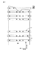
より正確に、図3および図4は、全部で17の吸着カップモジュール2を有する4つのブリッジレールモジュール1を含む本発明の実施形態の設計されたテーブルに配置された金属プレート10(コイル)の平面図を示す。当業者は、ブリッジレールモジュール1の数を4つ以上または4つ以下にできることを認める。ブリッジレールモジュール1は、互いに平行に設置されることが好ましく、しかし、Y軸方向に対して異なる方向に設定することも可能である。切断されるべき被加工物が持ち込まれる前に、これらのブリッジレールモジュールは、設計されたテーブルの所定の位置に固定される。いったん、被加工物が静止した位置にあると、吸着カップモジュールは、切断される間、その場所に材料を保持するために十分な吸着を生じるために起動される。
More precisely, FIGS. 3 and 4 show a metal plate 10 (coil) arranged on a designed table of an embodiment of the invention comprising four
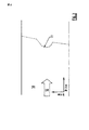
図2,3および4は、設計されたテーブル上での被加工物の工程を提示する連続したコイル供給の一例を示す。被加工物は、各工程の終わりで定期的に止められる。 2, 3 and 4 show an example of a continuous coil supply that presents the process of the workpiece on the designed table. The workpiece is periodically stopped at the end of each process.
図3において、設計されたテーブルのブリッジレールモジュールは、新たに切断を開始する直前の位置に示される。図4において、同じく新たな切断線11および切断位置決め孔3の直後の状態を示す。このような被加工物の周期的な供給と停止を可能にするため、コイル減速ループは、連続したコイル型抜き作業において標準的である適所に配置され得る。レーザ切断は、2つの連続するブリッジレールモジュール1の間で、平坦な金属プレート10(コイル)に実施された。さらに、2つの参照位置表示孔3も、ブランク材を形成する金属プレート10に切り抜かれた。
In FIG. 3, the bridge rail module of the designed table is shown in a position just before starting a new cut. In FIG. 4, the state immediately after the new cutting line 11 and the cutting positioning hole 3 is also shown. In order to allow such periodic feeding and stopping of the workpiece, the coil deceleration loop can be placed in place that is standard in continuous coil punching operations. Laser cutting was performed on a flat metal plate 10 (coil) between two successive
図5は、図4のレーザ切断作業の後で得られた周囲ブランク材4を示す。この周囲ブランク材4は、その端部に設定された切断線11,11’においてレーザ切断された。線11および11’は、図3および図4に示し上述したように、それぞれ2つの連続する切断の間に得られた。周囲ブランク材4は、さらに2つの参照位置表示孔3を含む。当業者は、参照位置表示孔3の数は、2から換えることも可能であることが理解する。 FIG. 5 shows the surrounding blank 4 obtained after the laser cutting operation of FIG. This peripheral blank 4 was laser cut at cutting lines 11 and 11 'set at the ends thereof. Lines 11 and 11 'were obtained between two successive cuts, respectively, as shown in FIGS. 3 and 4 and described above. The peripheral blank 4 further includes two reference position display holes 3. A person skilled in the art understands that the number of the reference position display holes 3 can be changed from two.
消耗性の歯付バーブリッジの従来の格子の代わりに、本発明の一実施形態によって、閉ループプロファイリングの高さセンサを拡張的に装備していなくてもレーザ切断機に必要最小の材料支持だけでなく、切断中に所定の位置に材料を保持する手段を備える頑丈で自在な柔軟性の設計されたテーブルを得るために、提案される。テーブルの架台は、頑丈な構造でなければならない。そして、少なくとも一方のX軸側に沿ったX軸ガイドを備えなければならない。さらに加えて、過度の熱変形を受けずに直接または反射したレーザ照射を持続できるべきである。その場合、ブリッジレールモジュールは、X軸またはY軸のいずれかに平行に向けられ得る。 Instead of the conventional grid of consumable toothed bar bridges, an embodiment of the present invention allows only the minimum material support required for a laser cutting machine without the need for extensively equipped with a closed loop profiling height sensor. Rather, it is proposed to obtain a sturdy and flexible designed table with means to hold the material in place during cutting. The table mount must be sturdy. An X-axis guide along at least one X-axis side must be provided. In addition, it should be possible to sustain direct or reflected laser irradiation without excessive thermal deformation. In that case, the bridge rail module may be oriented parallel to either the X-axis or the Y-axis.
設計されたテーブルは、そのY軸を横切って(Y軸に平行にまたは他の方向に)たくさんの必要なブリッジレールモジュール1を含む必要がある。これらのブリッジレールモジュール1は、テーブルのX軸に沿って任意の位置に位置決めするために、テーブル架台のX軸レールに沿って許容するべく移動可能である。書くブリッジレールモジュール1は、清掃および/または保守や設定のためにテーブルから簡単に取り外すことができる。これらのブリッジレールモジュール1は、取り外された廃棄部分が落下してテーブルの直下に配置された廃材コンベアによって収集されるように、可能な限り狭く設計されるべき頑丈な剛体構造である。もし必要ならば、部分プログラムは、排出および回収のためにブリッジレールモジュールの格子を通って簡単に落ちるより小さい断片に工学廃材を切断するために、追加切断シーケンスを追加してもよい。これらのモジュール1は、任意の水冷システムの溝を含んでいてもよい。任意に、落下しない設計された廃材片は、予め設計された異なる手段によって、排出および回収される。
The designed table should contain a number of necessary
各ブリッジレールモジュール1は、ブリッジレールに沿ってスライド可能に、頑丈な吸引カップモジュール2および位置ピンモジュール5を含む。たくさんの吸着カップ2と位置ピンモジュール5を必要な限り長く使用できるように、与えられたブリッジレールモジュール1に空間的にはまり込むことができる。
Each
設計されたテーブル架台、ブリッジレールモジュール1および吸着カップモジュール2は、適切に加工された表面を有している。その表面は、平坦にできる、または、局部的に支持されないとともに、吸着カップモジュール2との間の空間に張力を生じさせることを含め、材料すなわち切断されるべき金属プレート10をその場に保持するための把持力に匹敵する吸引力を生じる。これらモジュール2の支持面もまたこれらの上に載置されるブランク材4の参照高さ面として提供される。支持面は、ブリッジレールモジュール表面に対して上昇する。
The designed table mount,
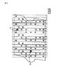
図6および図7は、いくつかのブリッジレールモジュール1が上述のようにブランク材4を形成する金属プレート10を貫通した参照位置表示孔3を探し出し/位置を示すのに使用されるピン位置モジュール5を含む他の実施形態を示す。
6 and 7 show a pin position module in which several
図5および図6は、コイル供給装置から取り外される前に多数のより小さなブランク材断片に切断される周囲ブランク材4を示し、図7は、多数のより小さなブランク材断片6にブランク材4を切断する状態を示す。
FIGS. 5 and 6 show a peripheral blank 4 that is cut into a number of smaller blank pieces before being removed from the coil feeder, and FIG. 7 shows the blank 4 in a number of smaller
これらの吸着カップ2およびピン位置表示モジュール5は、ネスティングおよびレーザヘッドの部分プログラムの機能として戦略上配置される。切断焦点合わせヘッドの経路12は、望ましくは、レーザが出力中である場合吸着カップモジュール2を決して横切らないことが好ましい。これは、落下せずにひっくり返ること、および、切断ヘッドの経路上に衝突物として突出することから部品を除去する。寸法精度公差に切断される部品を導くことができる入熱の熱応力や残留応力の開放によって誘発され、材料の位置が変位することを抑制する。
The suction cup 2 and the pin position display module 5 are strategically arranged as functions of a nesting and laser head partial program. The
これらの吸着カップ2およびピン位置支持モジュール5は、洗浄、メンテナンス、補修目的のために容易に変えられなければならない。テーブル全体は、剛性を有し、据付の際にレベルだしができ、したがって、すべての吸着カップモジュール2の表面は、周囲ブランク材4が載置される同じ標準高さの表面にある。それらが被加工物を引掻かず、永久に変形しない限り、そして、高さ変化の傾斜が作業範囲を横切って20mm移動する間に0.5mmを超えない限り、小さい高さ変動は、作業範囲上で許容される。 These suction cups 2 and pin position support module 5 must be easily changed for cleaning, maintenance and repair purposes. The entire table is rigid and can be leveled during installation, so the surfaces of all suction cup modules 2 are at the same standard height surface on which the surrounding blank 4 is placed. As long as they do not scratch the workpiece and are not permanently deformed, and as long as the slope of the height change does not exceed 0.5 mm while moving 20 mm across the work range, small height fluctuations are Allowed above.
図8Aに示すように、吸着カップモジュールのすべての構成要素は、吸引して押さえた状態に被加工物が保持される吸着カップの標準参照面を向けるため機械加工される。これらの構成要素は、円形、四角形、または適切かつ十分な形で、幅Lcを有する。供給および回収される圧縮ガスまたは空気のための急速取り外しは、オプションである。 As shown in FIG. 8A, all the components of the suction cup module are machined to point the standard reference surface of the suction cup on which the workpiece is held in a sucked and pressed state. These components have a width Lc in the form of a circle, a rectangle, or any suitable and sufficient shape. Rapid removal for compressed gas or air supplied and recovered is optional.
吸着カップモジュール2は、例えば、低圧、すなわち、大気圧よりも低い圧力(<1atm)を作り出すことのできる真空ポンプまたは他のいかなる真空装置のような、少なくとも真空源と連通している。したがって、切断されるべき断片をしっかりと保持することを許容する吸着カップモジュール2において、吸着効果を得る。 The suction cup module 2 is in communication with at least a vacuum source, such as a vacuum pump or any other vacuum device capable of creating a low pressure, i.e., a pressure lower than atmospheric pressure (<1 atm). Therefore, an adsorption effect is obtained in the adsorption cup module 2 that allows the fragments to be cut to be held firmly.
図8Bに示すように、各ブリッジレールモジュール1は、参照高さ表面として機能するので、剛体で無ければならない。ブリッジレールモジュール1は、頑丈でメンテナンスの目的のために簡単に洗浄されなければならない。吸着カップモジュール2参照表面の幅Lcは、ブリッジレールモジュールの幅(またはもし筒状であるなら直径)Lbより小さいまたは大きい。設計されたテーブル上に、吸気カップモジュール2は、異なる大きさおよび形状を有することができるが、ブランク材が載置されるすべての適切な参照表面姿勢のように設定されなければならない。そして多くの場合、設計されたテーブルは、被加工物を水平姿勢に向け、切断の間、選択的に、本発明は、レーザ切断の間、設計されたテーブルが被加工物表面を非水平姿勢または鉛直姿勢に向けることができる設定を含む。
As shown in FIG. 8B, each
図9は、本発明の装置を装備することのできる高速度レーザ材料取り装置の実施形態を示す。見ることができるように、第1のライン20または周囲ブランク材4を取り外すためのコイル供給ステーションと、第2のライン21または最終独立部品または第1のライン20で得られた周囲ブランクの更なる切断から得られるブランク片6を取り外すためのブランク供給ステーションと、の2つのラインを装置は含む。
FIG. 9 shows an embodiment of a high speed laser material removal apparatus that can be equipped with the apparatus of the present invention. As can be seen, the coil supply station for removing the first line 20 or the surrounding blank 4 and further of the surrounding blank obtained in the second line 21 or the final independent part or the first line 20. The apparatus comprises two lines: a blank supply station for removing the
コイル供給ステーション20の一つのレーザは、一般に、最終部分あたりの周期時間がプレス型抜きよりも短い。したがって、ラインバランシング周期時間観点のために、その者は、2つのレーザ機械をコイル供給ステーション20に必要としない。しかしながら、レーザ機械をセットアップ、メンテナンスおよび補修するためのダウンタイムの間それは冗長性を許容する。しかしながら、少なくとも2つのレーザ機械をブランク供給ステーション21で使用することが推奨される。 One laser in the coil supply station 20 generally has a shorter period per last part than press die cutting. Thus, for line balancing period time perspective, the person does not need two laser machines in the coil supply station 20. However, it allows redundancy during downtime to set up, maintain and repair the laser machine. However, it is recommended to use at least two laser machines at the blank supply station 21.
切断作業の間、切断されるべき周囲ブランク材4または最終独立部分片6は、ブリッジレールモジュール1に複数の吸着モジュール2を装備した本発明に係る1つ(または複数)の装置手段によってしっかり保持される。ブリッジレールモジュール1は、とりわけブランク材供給ステーション21で使用される場合、好ましくは位置決めピンモジュール5をさらに備える。
During the cutting operation, the surrounding blank 4 or the final
言い換えると、被加工物は、金属コイルから供給され、第1の切断機による第1の切断で少なくとも1つの周囲ブランク材になり、そのあと、周囲ブランク材は、いくつかのより小さい独立した最終ブランク材に切断されるために第2の切断機に供給される。 In other words, the workpiece is fed from a metal coil and becomes the at least one peripheral blank in the first cut by the first cutting machine, after which the peripheral blank is several smaller independent final pieces. A second cutting machine is fed to be cut into a blank material.
全部で6つのレーザ機械を有した総合レーザ材料取りシステムは、プレスラインのそれと同等の処理能力を有する。各レーザ機械は、最大にした「ビーム・オン」の価値付加時間を利用する必要がある。すなわち、材料ハンドリングは、レーザ切断を待たなければならず、回避できない。 An integrated laser material picking system with a total of six laser machines has a processing capacity equivalent to that of a press line. Each laser machine needs to make use of maximized “beam on” value added time. That is, material handling must wait for laser cutting and cannot be avoided.
ブランク材供給ステーションのために、レーザ切断機は、2つのテーブルを有していることが好ましい。すなわち一方でレーザ切断し、他方で積み/降ろしする。 For the blank supply station, the laser cutting machine preferably has two tables. That is, laser cutting on the one hand and loading / unloading on the other hand.
コイル供給ステーションは、周囲ブランク材の輪郭を取り除き、それがレーザ切断であるなら、好ましくは、廃材を取り除かずに、追加の切断を行なう。これは、コイル供給ステーションおよびブランク材供給ステーションの間の切断長さを均衡にすることを可能にする。 The coil supply station removes the outline of the surrounding blank and, if it is a laser cut, preferably performs an additional cut without removing the waste. This makes it possible to balance the cutting length between the coil supply station and the blank supply station.
コイルの各進行あたりの切断は、一般に数秒、通常3−4秒、要する。したがって、取り外した周囲ブランク材の輪郭を撤去するか積み重ねるための材料搬送に要する十分な時間を与える。 Cutting the coil per progression generally takes several seconds, usually 3-4 seconds. Thus, sufficient time is taken to transport the material to remove or stack the contour of the removed peripheral blank.
この概念を有する設計により、コイル供給ステーションは、取り除かれた廃材を好ましくは発生させないので、廃材を撤去するために要する時間によって、潜在的に妨げられないか、減速されない。切断中のコイル支持装置は、コイル供給ステーションのレーザ機械のために簡素化される。 By design with this concept, the coil supply station preferably does not generate removed waste material, so it is not potentially hindered or slowed down by the time required to remove the waste material. The coil support device during cutting is simplified for the laser machine of the coil supply station.
装置は、切断するべきプレートをX軸に沿って動かす動作機構を含む。この種の動作機構は、当技術分野において周知である。 The apparatus includes an operating mechanism that moves the plate to be cut along the X axis. This type of operating mechanism is well known in the art.
さらに、装置は、レーザ切断に使用される他の周知の要素を1つ(または数個)含むことができる。
−ファイバレーザ発振器のような、レーザ光線を発生するレーザ発振器、
−被加工物を切断するためのレーザ切断ヘッド、
−切断中のレーザ光線を補助するために使用されるアシストガスまたは混合ガスを貯留およびレーザヘッドに供給するための、ガス導管および/またはガスボンベや貯蔵容器など、ガス源、
−所望する軌跡に沿って切断を操作するために被加工物に対応して、レーザ切断ヘッドを動かすための装置、
−レーザヘッドを操縦するためのCNCまたはそれに相当するような制御装置、
−等。
In addition, the apparatus may include one (or several) other known elements used for laser cutting.
A laser oscillator that generates a laser beam, such as a fiber laser oscillator;
A laser cutting head for cutting the workpiece,
A gas source, such as a gas conduit and / or gas cylinder or storage container, for storing and supplying an assist gas or gas mixture used to assist the laser beam during cutting to the storage and laser head;
An apparatus for moving the laser cutting head in response to the workpiece to manipulate the cutting along the desired trajectory;
A control device such as a CNC or equivalent for maneuvering the laser head,
-Etc.
設計されたテーブルは、そのY軸を横切って(Y軸に平行にまたは他の方向に)たくさんの必要なブリッジレールモジュール1を含む必要がある。これらのブリッジレールモジュール1は、テーブルのX軸に沿って任意の位置に位置決めするために、テーブル架台のX軸レールに沿って許容するべく移動可能である。各ブリッジレールモジュール1は、清掃および/または保守や設定のためにテーブルから簡単に取り外すことができる。これらのブリッジレールモジュール1は、取り外された廃棄部分が落下してテーブルの直下に配置された廃材コンベアによって収集されるように、可能な限り狭く設計されるべき頑丈な剛体構造である。もし必要ならば、部分プログラムは、排出および回収のためにブリッジレールモジュールの格子を通って簡単に落ちるより小さい断片に工学廃材を切断するために、追加切断シーケンスを追加してもよい。これらのモジュール1は、任意の水冷システムの溝を含んでいてもよい。任意に、落下しない設計された廃材片は、予め設計された異なる手段によって、排出および回収される。
The designed table should contain a number of necessary
Claims (14)
前記支持テーブル架台の前記Y軸を横切って設けられ、それぞれ少なくとも1つの吸着カップモジュール(2)を有した1または複数のブリッジレールモジュール(1)と、
を備えることを特徴とするレーザ切断用の装置。 A rigid support table frame having an X axis and a Y axis;
One or more bridge rail modules (1) provided across the Y axis of the support table pedestal, each having at least one suction cup module (2);
An apparatus for laser cutting, comprising:
複数のブリッジレールモジュール(1)を備え、各ブリッジレールモジュール(1)は複数の吸着カップモジュール(2)を備えることを特徴とする。 The apparatus of claim 1.
A plurality of bridge rail modules (1) are provided, and each bridge rail module (1) includes a plurality of suction cup modules (2).
各前記吸着カップモジュール(2)は、少なくとも真空源にそれぞれ流体接続されていることを特徴とする。 The apparatus of claim 1 or claim 2,
Each of the suction cup modules (2) is fluidly connected to at least a vacuum source.
前記支持テーブル架台は、平坦であることを特徴とする。 The apparatus according to any one of claims 1 to 3,
The support table mount is flat.
1または複数の前記ブリッジレールモジュール(1)は、少なくとも1つのピン位置決めモジュール(5)を備えることを特徴とする。 The apparatus according to any one of claims 1 to 4,
The one or more bridge rail modules (1) are characterized in that they comprise at least one pin positioning module (5).
前記ブリッジレールモジュール(1)は、互いに平行であることを特徴とする。 The device according to any one of claims 1 to 5,
The bridge rail modules (1) are parallel to each other.
切断されるべきプレートを前記X軸に沿って移動させる動作機構をさらに備えることを特徴とする。 The apparatus according to any one of claims 1 to 6,
It further comprises an operation mechanism for moving the plate to be cut along the X axis.
前記支持テーブル架台は、切断の間、概ね平坦な切断されるべき被加工物の表面を非水平姿勢に向けることを特徴とする。 The apparatus according to any one of claims 1 to 7,
The support table gantry is characterized in that, during cutting, the surface of the workpiece to be cut substantially flat is directed to a non-horizontal posture.
前記支持テーブル架台は、切断の間、切断されるべき概ね平坦な被加工物の表面を鉛直姿勢に向けることを特徴とする。 The apparatus according to any one of claims 1 to 8,
The support table pedestal is characterized in that during cutting, the surface of the generally flat workpiece to be cut is oriented in a vertical position.
少なくとも1つのレーザ切断ヘッドをさらに備えることを特徴とする。 The device according to any one of claims 1 to 9,
Further comprising at least one laser cutting head.
a)レーザ切断装置を準備すること、
b)切断すべき金属プレートを準備すること、
c)前記金属プレートを真空吸着保持および維持するために請求項1に係る装置を準備すること、
d)それぞれが少なくとも1つの吸着カップモジュールを有した1または複数のブリッジレールモジュールによってその姿勢に前記金属プレートを真空吸引保持および維持している間に、前記レーザ切断装置によって出力されたレーザ光線によって前記金属プレートを切断すること
を含むことを特徴とする工法。 A method of laser cutting a metal plate,
a) preparing a laser cutting device;
b) preparing a metal plate to be cut;
c) providing an apparatus according to claim 1 to hold and maintain the metal plate by vacuum suction;
d) by means of a laser beam output by the laser cutting device, while holding and maintaining the metal plate in vacuum suction in its position by one or more bridge rail modules each having at least one suction cup module A method comprising cutting the metal plate.
前記金属プレートは、金属コイルであることを特徴とする。 In the construction method according to claim 11,
The metal plate is a metal coil.
前記金属プレートは、1つの主ブランク材またはいくつかのブランク断片に切断されることを特徴とする。 In the construction method according to claim 11 or claim 12,
The metal plate is cut into one main blank or several blank pieces.
被加工物は、第1の切断機によって少なくとも1つの周囲ブランク材に第1の切断をされるべく金属コイルから供給され、次に前記周囲ブランク材は、複数の小さな個別の最終ブランク材に切断されるべく第2の切断機に供給されることを特徴とする。 In the construction method according to any one of claims 11 to 13,
The workpiece is fed from a metal coil to be first cut into at least one surrounding blank by a first cutting machine, and then the surrounding blank is cut into a plurality of small individual final blanks. The second cutting machine is preferably supplied to the second cutting machine.
Applications Claiming Priority (3)
| Application Number | Priority Date | Filing Date | Title |
|---|---|---|---|
| US11573108P | 2008-11-18 | 2008-11-18 | |
| US61/115,731 | 2008-11-18 | ||
| PCT/EP2009/064803 WO2010057794A1 (en) | 2008-11-18 | 2009-11-09 | Support table frame for high speed laser blanking |
Publications (1)
| Publication Number | Publication Date |
|---|---|
| JP2012509177A true JP2012509177A (en) | 2012-04-19 |
Family
ID=41682558
Family Applications (1)
| Application Number | Title | Priority Date | Filing Date |
|---|---|---|---|
| JP2011535979A Pending JP2012509177A (en) | 2008-11-18 | 2009-11-09 | Support table for high-speed laser material removal |
Country Status (7)
| Country | Link |
|---|---|
| US (1) | US8367969B2 (en) |
| EP (1) | EP2346641B1 (en) |
| JP (1) | JP2012509177A (en) |
| KR (1) | KR20110095267A (en) |
| CN (1) | CN102216025B (en) |
| ES (1) | ES2671454T3 (en) |
| WO (1) | WO2010057794A1 (en) |
Cited By (2)
| Publication number | Priority date | Publication date | Assignee | Title |
|---|---|---|---|---|
| JP6095867B1 (en) * | 2016-03-25 | 2017-03-15 | 三菱電機株式会社 | Laser processing machine, processing equipment, setting device and program |
| JP2023550156A (en) * | 2020-11-23 | 2023-11-30 | アルセロールミタル | Process and equipment for laser cutting ultra-high strength metal materials |
Families Citing this family (27)
| Publication number | Priority date | Publication date | Assignee | Title |
|---|---|---|---|---|
| EP2355951A1 (en) * | 2008-11-19 | 2011-08-17 | L'Air Liquide Société Anonyme pour l'Etude et l'Exploitation des Procédés Georges Claude | A process for laser cutting a metal plate |
| DE102011003395B3 (en) * | 2011-01-31 | 2012-03-29 | Trumpf Laser- Und Systemtechnik Gmbh | Method for separating an edge section of a workpiece by means of a laser cutting section and associated laser cutting device |
| US9354630B2 (en) * | 2011-05-19 | 2016-05-31 | Universal Laser Systems, Inc. | Flexible laser manufacturing systems and associated methods of use and manufacture |
| EP2823932B1 (en) * | 2012-03-08 | 2021-09-29 | Baoshan Iron & Steel Co., Ltd. | Motor vehicle panel blanking method |
| CN103600171B (en) * | 2013-04-28 | 2015-12-09 | 宝山钢铁股份有限公司 | The method and system of a kind of metallic plate loading and unloading and cutting |
| CN103600170B (en) * | 2013-04-28 | 2015-08-26 | 宝山钢铁股份有限公司 | A kind of longitudinal metal plate loading and unloading and cutting method and system thereof |
| CN103600175B (en) * | 2013-04-28 | 2016-06-29 | 宝山钢铁股份有限公司 | A kind of cut liner plate mould and method for arranging thereof |
| CN103600234A (en) * | 2013-04-28 | 2014-02-26 | 宝山钢铁股份有限公司 | Steel plate combination shearing method and system |
| DE102013210878A1 (en) * | 2013-06-11 | 2014-12-11 | Schuler Automation Gmbh & Co. Kg | Method and device for producing a sheet metal part |
| US10026540B2 (en) * | 2014-04-02 | 2018-07-17 | Vishay Dale Electronics, Llc | Magnetic components and methods for making same |
| US8923656B1 (en) | 2014-05-09 | 2014-12-30 | Silhouette America, Inc. | Correction of acquired images for cutting pattern creation |
| CN104139352B (en) * | 2014-07-18 | 2016-08-24 | 北京航天发射技术研究所 | A kind of mechanical docking arrangement |
| DE102015212444B4 (en) | 2015-06-12 | 2025-01-30 | Schuler Pressen Gmbh | Process for producing a sheet metal blank |
| DE102015211017B4 (en) * | 2015-06-16 | 2017-06-14 | Trumpf Werkzeugmaschinen Gmbh + Co. Kg | Method for unloading a cut-free part of the workpiece, associated laser cutting machine and computer program product |
| CN105328353B (en) * | 2015-10-30 | 2017-03-22 | 安徽江淮汽车集团股份有限公司 | cutting platform of laser cutting machine |
| CN106141796A (en) * | 2016-08-18 | 2016-11-23 | 苏州市华宁机械制造有限公司 | A kind of band adsorbs the cutting bed of scrappy part |
| CN107020587B (en) * | 2017-03-28 | 2019-07-09 | 珠海格力电器股份有限公司 | Clamping device and processing method of air conditioner |
| CN106863180B (en) * | 2017-03-28 | 2019-06-14 | 珠海格力智能装备技术研究院有限公司 | Clamping device |
| DE102018208715B4 (en) * | 2017-12-20 | 2025-06-18 | Magna Exteriors Gmbh | Method for producing a plastic component, and plastic component |
| DE102018123363B4 (en) * | 2018-09-24 | 2021-01-07 | Bystronic Laser Ag | Procedure for collision avoidance and laser processing machine |
| DE102018125620A1 (en) * | 2018-10-16 | 2020-04-16 | Schuler Pressen Gmbh | Method and device for cutting a sheet metal blank from a continuously conveyed sheet metal strip |
| JP6758441B2 (en) * | 2019-02-18 | 2020-09-23 | 株式会社アマダ | Laser processing machine, laser processing method, and processing program creation device |
| JP6923585B2 (en) * | 2019-03-18 | 2021-08-18 | ファナック株式会社 | Machine learning equipment, control equipment, laser processing machines, and machine learning methods |
| CN112809205B (en) * | 2021-02-05 | 2022-11-01 | 广西鑫润精密机械有限公司 | Optical fiber laser manufacturing method of stainless steel screen mesh |
| DE102021116899A1 (en) * | 2021-06-30 | 2023-01-05 | Messer Cutting Systems Gmbh | Process for thermal processing of a workpiece with a thermal processing machine |
| DE102022112048A1 (en) * | 2022-05-13 | 2023-11-16 | TRUMPF Werkzeugmaschinen SE + Co. KG | Sorting device, separation system and associated methods |
| DE102023114159A1 (en) * | 2023-05-30 | 2024-12-05 | TRUMPF Werkzeugmaschinen SE + Co. KG | MACHINE AND METHOD FOR LASER CUTTING A PLATE-SHAPED WORKPIECE |
Citations (11)
| Publication number | Priority date | Publication date | Assignee | Title |
|---|---|---|---|---|
| JPS62105778U (en) * | 1985-12-23 | 1987-07-06 | ||
| JPS63144925A (en) * | 1986-12-05 | 1988-06-17 | Nippei Toyama Corp | Clamp lifter device for cut surface working |
| JPS63144922A (en) * | 1986-12-05 | 1988-06-17 | Nippei Toyama Corp | Combined cutting device for nonferrous metal |
| JPS63165088A (en) * | 1985-12-27 | 1988-07-08 | Chiyuushiyou Kigyo Jigyodan | Laser beam machine |
| JPS63165089A (en) * | 1986-01-30 | 1988-07-08 | Chiyuushiyou Kigyo Jigyodan | Laser beam machine |
| JPH0596434A (en) * | 1991-04-05 | 1993-04-20 | Manuel Torres Martinez | Device for mounting machine tool for supporting and machining workpiece |
| JPH073882U (en) * | 1993-06-23 | 1995-01-20 | 株式会社小松製作所 | Work positioning device for thermal cutting machine |
| JPH07122201A (en) * | 1993-10-25 | 1995-05-12 | Toppan Printing Co Ltd | Shadow mask material and method for removing connection portion of shadow mask material |
| JPH08309586A (en) * | 1995-05-24 | 1996-11-26 | Amada Eng Center:Kk | Thermal cutting device |
| JPH09219482A (en) * | 1996-02-08 | 1997-08-19 | Hitachi Constr Mach Co Ltd | Positioning device for semiconductor device and dam bar cutting device |
| JP2001105404A (en) * | 1999-10-05 | 2001-04-17 | Heian Corp | Suction table device of nc machine |
Family Cites Families (24)
| Publication number | Priority date | Publication date | Assignee | Title |
|---|---|---|---|---|
| US3736402A (en) * | 1970-09-17 | 1973-05-29 | Coherent Radiation | Automated laser tool |
| US4039799A (en) * | 1973-05-22 | 1977-08-02 | Stumpf Guenter | Device for cutting sheet material |
| DE2933700C2 (en) * | 1979-08-21 | 1984-04-19 | C. Behrens Ag, 3220 Alfeld | Machine tool with a melt cutting device designed as a laser cutting device |
| FR2599291A1 (en) | 1986-05-28 | 1987-12-04 | Benet Jacques | MACHINE FOR THE SEALING OF LINKS SURROUNDING PARCELS INCLUDING COILS AND PACKETS OF SHEETS |
| US4796341A (en) * | 1988-01-11 | 1989-01-10 | Fmc Corporation | Plate routing method and apparatus |
| ES2043166T3 (en) * | 1990-04-06 | 1993-12-16 | Thyssen Industrie | PROCEDURE TO WELD ONE WITH ANOTHER STEEL SHEET OF DIFFERENT OR EQUAL THICKNESS - ALSO THIN SHEETS - BY WELDING BY LASER RAY IN CONTINUOUS DIAMOND. |
| DE4017983A1 (en) * | 1990-06-05 | 1991-12-12 | Airbus Gmbh | DEVICE FOR SETTING UP AND CLAMPING WORKPIECES |
| US5341717A (en) * | 1993-05-05 | 1994-08-30 | Feldman Richard L | Tolerance compensating assembly/positioning system and method of use |
| DE9403242U1 (en) * | 1994-02-26 | 1994-05-05 | IMA-Norte Maschinenfabriken Klessmann GmbH, 33334 Gütersloh | Workpiece support |
| US5632915A (en) * | 1994-08-29 | 1997-05-27 | Gerber Garment Technology, Inc. | Laser material processing apparatus and a work table therefor |
| US5854460A (en) * | 1996-05-07 | 1998-12-29 | Cincinnati Incorporated | Linear motor driven laser cutting machine |
| DE19853366B4 (en) * | 1998-11-19 | 2007-07-19 | Schuler Pressen Gmbh & Co. Kg | Apparatus and method for forming |
| US6310317B1 (en) * | 1999-11-04 | 2001-10-30 | Lillbacka Jetair Oy | Laser beam guide |
| US6515256B1 (en) * | 2000-04-13 | 2003-02-04 | Vincent P. Battaglia | Process for laser machining continuous metal strip |
| IT1316478B1 (en) * | 2000-04-14 | 2003-04-22 | Iron Spa | PROCEDURE FOR LASER CUTTING AND / OR PLASMA FROM TAPE, PARTICULARLY OF METAL IN COILS, AND RELATIVE LINE OF CUTTING IN |
| DE10019368B4 (en) * | 2000-04-18 | 2016-11-03 | Schuler Pressen Gmbh | Method and device for producing sheet metal |
| DE10111662A1 (en) * | 2001-03-09 | 2002-09-26 | Thyssenkrupp Stahl Ag | Method and device for robot-controlled cutting and welding with laser radiation |
| ATE258835T1 (en) * | 2001-08-18 | 2004-02-15 | Trumpf Werkzeugmaschinen Gmbh | MACHINE TOOL FOR PROCESSING WORKPIECES USING A LASER BEAM |
| SG121700A1 (en) * | 2001-12-28 | 2006-05-26 | Jetsis Int Pte Ltd | A method and related apparatus for cutting a product from a sheet material |
| DE10245371B4 (en) * | 2002-09-28 | 2006-06-01 | Trumpf Sachsen Gmbh | Method and device for cutting sheet metal blanks |
| DE20319159U1 (en) * | 2003-12-11 | 2004-03-11 | Laufenberg, Wolfgang | Clamping device for large irregularly shaped item like body part of vehicle, comprising linear movable and swivel mounted suction elements |
| US7630976B2 (en) * | 2005-05-10 | 2009-12-08 | Microsoft Corporation | Method and system for adapting search results to personal information needs |
| US7640280B2 (en) * | 2006-10-31 | 2009-12-29 | Rebit, Inc. | System for automatically shadowing data and file directory structures that are recorded on a computer memory |
| US8253064B2 (en) * | 2008-02-20 | 2012-08-28 | Automatic Feed Company | Progressive laser blanking device for high speed cutting |
-
2009
- 2009-11-09 KR KR1020117011198A patent/KR20110095267A/en not_active Ceased
- 2009-11-09 CN CN200980145835.3A patent/CN102216025B/en not_active Expired - Fee Related
- 2009-11-09 WO PCT/EP2009/064803 patent/WO2010057794A1/en not_active Ceased
- 2009-11-09 ES ES09752339.3T patent/ES2671454T3/en active Active
- 2009-11-09 EP EP09752339.3A patent/EP2346641B1/en not_active Not-in-force
- 2009-11-09 JP JP2011535979A patent/JP2012509177A/en active Pending
- 2009-11-17 US US12/619,848 patent/US8367969B2/en not_active Expired - Fee Related
Patent Citations (11)
| Publication number | Priority date | Publication date | Assignee | Title |
|---|---|---|---|---|
| JPS62105778U (en) * | 1985-12-23 | 1987-07-06 | ||
| JPS63165088A (en) * | 1985-12-27 | 1988-07-08 | Chiyuushiyou Kigyo Jigyodan | Laser beam machine |
| JPS63165089A (en) * | 1986-01-30 | 1988-07-08 | Chiyuushiyou Kigyo Jigyodan | Laser beam machine |
| JPS63144925A (en) * | 1986-12-05 | 1988-06-17 | Nippei Toyama Corp | Clamp lifter device for cut surface working |
| JPS63144922A (en) * | 1986-12-05 | 1988-06-17 | Nippei Toyama Corp | Combined cutting device for nonferrous metal |
| JPH0596434A (en) * | 1991-04-05 | 1993-04-20 | Manuel Torres Martinez | Device for mounting machine tool for supporting and machining workpiece |
| JPH073882U (en) * | 1993-06-23 | 1995-01-20 | 株式会社小松製作所 | Work positioning device for thermal cutting machine |
| JPH07122201A (en) * | 1993-10-25 | 1995-05-12 | Toppan Printing Co Ltd | Shadow mask material and method for removing connection portion of shadow mask material |
| JPH08309586A (en) * | 1995-05-24 | 1996-11-26 | Amada Eng Center:Kk | Thermal cutting device |
| JPH09219482A (en) * | 1996-02-08 | 1997-08-19 | Hitachi Constr Mach Co Ltd | Positioning device for semiconductor device and dam bar cutting device |
| JP2001105404A (en) * | 1999-10-05 | 2001-04-17 | Heian Corp | Suction table device of nc machine |
Cited By (6)
| Publication number | Priority date | Publication date | Assignee | Title |
|---|---|---|---|---|
| JP6095867B1 (en) * | 2016-03-25 | 2017-03-15 | 三菱電機株式会社 | Laser processing machine, processing equipment, setting device and program |
| WO2017163419A1 (en) * | 2016-03-25 | 2017-09-28 | 三菱電機株式会社 | Laser processor, processing equipment, set-up device, program, and set-up method |
| CN107848072A (en) * | 2016-03-25 | 2018-03-27 | 三菱电机株式会社 | Laser machine, process equipment, setting device, program and establishing method |
| CN107848072B (en) * | 2016-03-25 | 2019-07-26 | 三菱电机株式会社 | Laser machine, process equipment, setting device and setting method |
| JP2023550156A (en) * | 2020-11-23 | 2023-11-30 | アルセロールミタル | Process and equipment for laser cutting ultra-high strength metal materials |
| JP7611387B2 (en) | 2020-11-23 | 2025-01-09 | アルセロールミタル | Process and apparatus for laser cutting ultra-high strength metallic materials |
Also Published As
| Publication number | Publication date |
|---|---|
| KR20110095267A (en) | 2011-08-24 |
| EP2346641B1 (en) | 2018-04-11 |
| EP2346641A1 (en) | 2011-07-27 |
| US8367969B2 (en) | 2013-02-05 |
| CN102216025B (en) | 2015-04-08 |
| ES2671454T3 (en) | 2018-06-06 |
| WO2010057794A1 (en) | 2010-05-27 |
| US20100122970A1 (en) | 2010-05-20 |
| CN102216025A (en) | 2011-10-12 |
Similar Documents
| Publication | Publication Date | Title |
|---|---|---|
| JP2012509177A (en) | Support table for high-speed laser material removal | |
| US8492677B2 (en) | Process for laser cutting a metal plate | |
| JP4290656B2 (en) | Laser cutting device, laser cutting method and laser cutting system | |
| JP4705139B2 (en) | Laser cutting device, laser cutting method and laser cutting system | |
| US8946587B2 (en) | Laser machining apparatus | |
| CN105935835B (en) | Sheet processing system and method for processing sheet material | |
| US20160144464A1 (en) | Workpiece Support For Use In A Machine Tool | |
| JP2005297007A (en) | Laser beam machine | |
| JP2008264862A (en) | Board processing system | |
| CN108176983A (en) | Press machine is cut in self-feeding | |
| JPH04228282A (en) | Method and apparatus for cutting off flat material | |
| CN105848802B (en) | Method and machine for deriving workpiece blanks from a cutting unit of a machine tool, as well as machining method and machine assembly for machining | |
| JP2019529124A (en) | Method and tool machine for processing a plate-like workpiece, in particular a sheet metal | |
| JP2005246524A (en) | Plate machining system | |
| JP2014044632A (en) | Operation management device for end material of work, its method and its processing system | |
| CN211310078U (en) | Flexible OLED display panel laser shape cutting equipment with cleaning function | |
| JP5959948B2 (en) | Wafer ring exchange device and chip mounting device | |
| US20070045258A1 (en) | Nozzle polishing device in laser processing machine | |
| JP2005153048A (en) | Machining apparatus | |
| JP7478001B2 (en) | Processing system and carrying method | |
| JP2013258300A (en) | Chip mounting device | |
| JP2011136356A (en) | Laser beam machine | |
| JP3114629U (en) | Lens cutting machine | |
| JPH05318224A (en) | Cutting device | |
| JP2016168752A (en) | Molded product take-out system |
Legal Events
| Date | Code | Title | Description |
|---|---|---|---|
| A621 | Written request for application examination |
Free format text: JAPANESE INTERMEDIATE CODE: A621 Effective date: 20120918 |
|
| A131 | Notification of reasons for refusal |
Free format text: JAPANESE INTERMEDIATE CODE: A131 Effective date: 20130924 |
|
| A601 | Written request for extension of time |
Free format text: JAPANESE INTERMEDIATE CODE: A601 Effective date: 20131224 |
|
| A602 | Written permission of extension of time |
Free format text: JAPANESE INTERMEDIATE CODE: A602 Effective date: 20140107 |
|
| A521 | Request for written amendment filed |
Free format text: JAPANESE INTERMEDIATE CODE: A523 Effective date: 20140324 |
|
| A02 | Decision of refusal |
Free format text: JAPANESE INTERMEDIATE CODE: A02 Effective date: 20140520 |