JP2012509757A - Corrugated packing material and column packed with this packing material - Google Patents
Corrugated packing material and column packed with this packing material Download PDFInfo
- Publication number
- JP2012509757A JP2012509757A JP2011536924A JP2011536924A JP2012509757A JP 2012509757 A JP2012509757 A JP 2012509757A JP 2011536924 A JP2011536924 A JP 2011536924A JP 2011536924 A JP2011536924 A JP 2011536924A JP 2012509757 A JP2012509757 A JP 2012509757A
- Authority
- JP
- Japan
- Prior art keywords
- strip
- bandlet
- ridge
- adjacent
- corrugated
- Prior art date
- Legal status (The legal status is an assumption and is not a legal conclusion. Google has not performed a legal analysis and makes no representation as to the accuracy of the status listed.)
- Withdrawn
Links
- 239000000463 material Substances 0.000 title claims abstract description 11
- 238000012856 packing Methods 0.000 title claims abstract description 6
- 239000000945 filler Substances 0.000 description 32
- 239000007788 liquid Substances 0.000 description 15
- 229910052751 metal Inorganic materials 0.000 description 6
- 239000002184 metal Substances 0.000 description 6
- PCTMTFRHKVHKIS-BMFZQQSSSA-N (1s,3r,4e,6e,8e,10e,12e,14e,16e,18s,19r,20r,21s,25r,27r,30r,31r,33s,35r,37s,38r)-3-[(2r,3s,4s,5s,6r)-4-amino-3,5-dihydroxy-6-methyloxan-2-yl]oxy-19,25,27,30,31,33,35,37-octahydroxy-18,20,21-trimethyl-23-oxo-22,39-dioxabicyclo[33.3.1]nonatriaconta-4,6,8,10 Chemical compound C1C=C2C[C@@H](OS(O)(=O)=O)CC[C@]2(C)[C@@H]2[C@@H]1[C@@H]1CC[C@H]([C@H](C)CCCC(C)C)[C@@]1(C)CC2.O[C@H]1[C@@H](N)[C@H](O)[C@@H](C)O[C@H]1O[C@H]1/C=C/C=C/C=C/C=C/C=C/C=C/C=C/[C@H](C)[C@@H](O)[C@@H](C)[C@H](C)OC(=O)C[C@H](O)C[C@H](O)CC[C@@H](O)[C@H](O)C[C@H](O)C[C@](O)(C[C@H](O)[C@H]2C(O)=O)O[C@H]2C1 PCTMTFRHKVHKIS-BMFZQQSSSA-N 0.000 description 3
- 238000005054 agglomeration Methods 0.000 description 3
- 230000002776 aggregation Effects 0.000 description 3
- 238000004821 distillation Methods 0.000 description 3
- 239000012808 vapor phase Substances 0.000 description 3
- 230000009471 action Effects 0.000 description 2
- 229910052782 aluminium Inorganic materials 0.000 description 2
- XAGFODPZIPBFFR-UHFFFAOYSA-N aluminium Chemical compound [Al] XAGFODPZIPBFFR-UHFFFAOYSA-N 0.000 description 2
- 230000008859 change Effects 0.000 description 2
- 230000000694 effects Effects 0.000 description 2
- 238000007654 immersion Methods 0.000 description 2
- 238000005304 joining Methods 0.000 description 2
- 238000000926 separation method Methods 0.000 description 2
- 238000009736 wetting Methods 0.000 description 2
- 238000005452 bending Methods 0.000 description 1
- PZTQVMXMKVTIRC-UHFFFAOYSA-L chembl2028348 Chemical compound [Ca+2].[O-]S(=O)(=O)C1=CC(C)=CC=C1N=NC1=C(O)C(C([O-])=O)=CC2=CC=CC=C12 PZTQVMXMKVTIRC-UHFFFAOYSA-L 0.000 description 1
- 238000002474 experimental method Methods 0.000 description 1
- 230000006872 improvement Effects 0.000 description 1
- 238000004519 manufacturing process Methods 0.000 description 1
- 230000021715 photosynthesis, light harvesting Effects 0.000 description 1
- 230000002028 premature Effects 0.000 description 1
- 230000009467 reduction Effects 0.000 description 1
- 230000007480 spreading Effects 0.000 description 1
- 238000003892 spreading Methods 0.000 description 1
- 238000004381 surface treatment Methods 0.000 description 1
- 238000011282 treatment Methods 0.000 description 1
Images




Classifications
-
- B—PERFORMING OPERATIONS; TRANSPORTING
- B01—PHYSICAL OR CHEMICAL PROCESSES OR APPARATUS IN GENERAL
- B01J—CHEMICAL OR PHYSICAL PROCESSES, e.g. CATALYSIS OR COLLOID CHEMISTRY; THEIR RELEVANT APPARATUS
- B01J19/00—Chemical, physical or physico-chemical processes in general; Their relevant apparatus
- B01J19/32—Packing elements in the form of grids or built-up elements for forming a unit or module inside the apparatus for mass or heat transfer
-
- B—PERFORMING OPERATIONS; TRANSPORTING
- B01—PHYSICAL OR CHEMICAL PROCESSES OR APPARATUS IN GENERAL
- B01J—CHEMICAL OR PHYSICAL PROCESSES, e.g. CATALYSIS OR COLLOID CHEMISTRY; THEIR RELEVANT APPARATUS
- B01J2219/00—Chemical, physical or physico-chemical processes in general; Their relevant apparatus
- B01J2219/32—Details relating to packing elements in the form of grids or built-up elements for forming a unit of module inside the apparatus for mass or heat transfer
- B01J2219/322—Basic shape of the elements
- B01J2219/32203—Sheets
- B01J2219/3221—Corrugated sheets
-
- B—PERFORMING OPERATIONS; TRANSPORTING
- B01—PHYSICAL OR CHEMICAL PROCESSES OR APPARATUS IN GENERAL
- B01J—CHEMICAL OR PHYSICAL PROCESSES, e.g. CATALYSIS OR COLLOID CHEMISTRY; THEIR RELEVANT APPARATUS
- B01J2219/00—Chemical, physical or physico-chemical processes in general; Their relevant apparatus
- B01J2219/32—Details relating to packing elements in the form of grids or built-up elements for forming a unit of module inside the apparatus for mass or heat transfer
- B01J2219/322—Basic shape of the elements
- B01J2219/32203—Sheets
- B01J2219/32213—Plurality of essentially parallel sheets
-
- B—PERFORMING OPERATIONS; TRANSPORTING
- B01—PHYSICAL OR CHEMICAL PROCESSES OR APPARATUS IN GENERAL
- B01J—CHEMICAL OR PHYSICAL PROCESSES, e.g. CATALYSIS OR COLLOID CHEMISTRY; THEIR RELEVANT APPARATUS
- B01J2219/00—Chemical, physical or physico-chemical processes in general; Their relevant apparatus
- B01J2219/32—Details relating to packing elements in the form of grids or built-up elements for forming a unit of module inside the apparatus for mass or heat transfer
- B01J2219/322—Basic shape of the elements
- B01J2219/32203—Sheets
- B01J2219/32224—Sheets characterised by the orientation of the sheet
- B01J2219/32227—Vertical orientation
-
- B—PERFORMING OPERATIONS; TRANSPORTING
- B01—PHYSICAL OR CHEMICAL PROCESSES OR APPARATUS IN GENERAL
- B01J—CHEMICAL OR PHYSICAL PROCESSES, e.g. CATALYSIS OR COLLOID CHEMISTRY; THEIR RELEVANT APPARATUS
- B01J2219/00—Chemical, physical or physico-chemical processes in general; Their relevant apparatus
- B01J2219/32—Details relating to packing elements in the form of grids or built-up elements for forming a unit of module inside the apparatus for mass or heat transfer
- B01J2219/322—Basic shape of the elements
- B01J2219/32203—Sheets
- B01J2219/32237—Sheets comprising apertures or perforations
-
- B—PERFORMING OPERATIONS; TRANSPORTING
- B01—PHYSICAL OR CHEMICAL PROCESSES OR APPARATUS IN GENERAL
- B01J—CHEMICAL OR PHYSICAL PROCESSES, e.g. CATALYSIS OR COLLOID CHEMISTRY; THEIR RELEVANT APPARATUS
- B01J2219/00—Chemical, physical or physico-chemical processes in general; Their relevant apparatus
- B01J2219/32—Details relating to packing elements in the form of grids or built-up elements for forming a unit of module inside the apparatus for mass or heat transfer
- B01J2219/322—Basic shape of the elements
- B01J2219/32203—Sheets
- B01J2219/32248—Sheets comprising areas that are raised or sunken from the plane of the sheet
-
- B—PERFORMING OPERATIONS; TRANSPORTING
- B01—PHYSICAL OR CHEMICAL PROCESSES OR APPARATUS IN GENERAL
- B01J—CHEMICAL OR PHYSICAL PROCESSES, e.g. CATALYSIS OR COLLOID CHEMISTRY; THEIR RELEVANT APPARATUS
- B01J2219/00—Chemical, physical or physico-chemical processes in general; Their relevant apparatus
- B01J2219/32—Details relating to packing elements in the form of grids or built-up elements for forming a unit of module inside the apparatus for mass or heat transfer
- B01J2219/324—Composition or microstructure of the elements
- B01J2219/32408—Metal
-
- Y—GENERAL TAGGING OF NEW TECHNOLOGICAL DEVELOPMENTS; GENERAL TAGGING OF CROSS-SECTIONAL TECHNOLOGIES SPANNING OVER SEVERAL SECTIONS OF THE IPC; TECHNICAL SUBJECTS COVERED BY FORMER USPC CROSS-REFERENCE ART COLLECTIONS [XRACs] AND DIGESTS
- Y10—TECHNICAL SUBJECTS COVERED BY FORMER USPC
- Y10T—TECHNICAL SUBJECTS COVERED BY FORMER US CLASSIFICATION
- Y10T137/00—Fluid handling
- Y10T137/8593—Systems
- Y10T137/85938—Non-valved flow dividers
Landscapes
- Chemical & Material Sciences (AREA)
- Physics & Mathematics (AREA)
- Thermal Sciences (AREA)
- Organic Chemistry (AREA)
- Chemical Kinetics & Catalysis (AREA)
- Physical Or Chemical Processes And Apparatus (AREA)
- Separation By Low-Temperature Treatments (AREA)
Abstract
この発明は、材料および/或いは熱交換カラムのための均一な充填材要素に関し、交互にされた複数のストリップ(1、2)と、少なくとも1つのアニュレット(7、9)と、を有する。各ストリップは、波形にされ、一般的に矩形を有し、1つのストリップを横切る複数の波形が、隣接する構造の波形に関して、50°から100°の間で指向されるように、複数のストリップが、互いに対向して配置され、波形の交差した構造を形成する。アニュレットは、ストリップの少なくとも1つの第1稜部(3、5)、およびストリップの少なくとも1つの第2稜部で同時に接触し、第2稜部が第1稜部に隣接する。 The invention relates to a uniform packing element for materials and / or heat exchange columns, comprising a plurality of alternating strips (1, 2) and at least one annular (7, 9). Each strip is corrugated and generally has a rectangular shape, so that the plurality of strips across one strip are oriented between 50 ° and 100 ° with respect to the corrugations of adjacent structures. Are arranged opposite to each other to form a cross-corrugated structure. The annulette contacts at the same time at least one first ridge (3, 5) of the strip and at least one second ridge of the strip, the second ridge being adjacent to the first ridge.
Description
本発明は、波形の交差した充填材に関し、この充填材を詰め込んだカラムに関する。 The present invention relates to corrugated packing materials and to a column packed with the packing materials.
通常使用される充填材は、略垂直な平らな面にそれぞれ配置され且つ互いに対向した平行な交互の波形を有する複数の波形のバンドからなる。これらの波形は、1つのバンドから次のバンドへ反対方向に傾斜して下がって行く。その穿孔率は、波形の交差した充填材と呼ばれるこれら充填材の約10%である。 Commonly used fillers consist of a plurality of corrugated bands, each arranged on a substantially vertical flat surface and having alternating alternating corrugations facing each other. These waveforms slope down in the opposite direction from one band to the next. Its perforation rate is about 10% of these fillers, called corrugated cross fillers.
図1は、充填材の6つの重ねられたバンドの等角透視図である。 FIG. 1 is an isometric view of six superimposed bands of filler.
GB−A−1004046は、波形の交差したタイプの充填材を開示している。 GB-A-1004046 discloses a corrugated crossing type filler.
CA−A−1095827は、波形の交差したバンドの一側から他側への液体の通過を許容する密集した小径の穿孔を追加することにより、このタイプの充填材の改良を提案している。 CA-A-1095827 proposes an improvement of this type of filler by adding dense small diameter perforations that allow the passage of liquid from one side of the corrugated crossed band to the other.
この充填材は、通常、図1に図示されているバンド1、2の形で、平らな製造物、すなわち単なる金属シートから製造される。これらバンドは、第1に、一種の波形の金属シートを形成するように、折り畳まれ(或いは湾曲され)、このバンドにおいて、その波形は、バンドの軸に関して傾斜されている。そして、これら折り畳まれた複数のバンドは、複数の部分に切断され、2つのバンドのうち1つの向きを交互に変えて重ねられる。
This filler is usually produced from a flat product, i.e. just a metal sheet, in the form of
このようにして得られた充填材の複数の部分は“充填物”と呼ばれる。 The portions of the filler thus obtained are called “fills”.
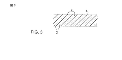
図2および図3に示すような単純な波形の場合において、波形の交差した充填材の説明を可能にする種々のパラメーターは、波の高さ(H)、折り曲げ角度(Y)、曲率半径(r)、および複数の波の傾斜(δ)である。かくして、稜線3および谷線5が形成される。

これら種々の特許は、主に、液体の広がりを助長するため、バンドの2つの面の間での液体のやりとりのため、または蒸気相の乱流のためといった、種々の理由により、充填材バンドに対する穿孔の追加を開示している。 These various patents are mainly used for various reasons, such as to promote liquid spreading, for the exchange of liquid between the two faces of the band, or for the turbulent flow of the vapor phase. Discloses the addition of perforations.
これら穿孔は、2つの広いカテゴリーに分類することができる。 These perforations can be classified into two broad categories.
・“小さい”寸法(液体の毛管現象の力が、良い濡れを維持するのに十分な)の穿孔。このような穿孔は、例えば、参照番号1、2、3、4、5、6のように、液体の連続したフィルムによって満たされることができ、或いは、下流のドライゾーンを生出することなく、液体がその周りを流れるのに十分に小さい。
Perforations of “small” dimensions (liquid capillary action force is sufficient to maintain good wetting). Such perforations can be filled with a continuous film of liquid, eg, with
・“大きい”寸法の穿孔、或いは広く開口したスロット。このような穿孔は、例えば、参照番号7、8、9、10、11のように、通常、蒸気相の乱流を助長するように仕向けられ(例えば、図1)、しかし、液体の流れを妨げる不利益や、下流のドライゾーンを生出する不利益を有することができる。一方、参照番号13、14は、厳しい幾何学的ストレスを犠牲にして気体側の乱流を増大する一方で、液体をそれほど多く妨害しない効果を有する。
これら複数の平らなバンドの追加は、充填材内で起きるガス/ガス妨害の減少或いは除去の目的のため上述した全てである。特に、充填材の2つのバンドのチャネルが90°で指向されていることから、2つのガス流が、その境界で妨害され、結果が、2つのガス流の螺旋移動である。これらの不和は、圧力損失の大きな部分の始まりであり、材料の交換のための値の全体ではない。平らなバンドを加えることは、この回転現象を減少し、エネルギーの散逸を減少する。 The addition of these multiple flat bands is all described above for the purpose of reducing or eliminating gas / gas interferences occurring in the filler. In particular, since the two band channels of the filler are oriented at 90 °, the two gas flows are obstructed at the boundary, and the result is a spiral movement of the two gas flows. These discords are the beginning of a large portion of pressure loss, not the overall value for material exchange. Adding a flat band reduces this rotational phenomenon and reduces energy dissipation.
平らなバンドの追加には多くの不利益がある。 There are many disadvantages to adding a flat band.
・新しい充填材の全体的な密度が増大する。そのため、全体的な密度と同等に達するように波形の交差の高さを増大する必要がある。このことは、ガス流内における集中の側面を強調し、分離動作を減少する。 • The overall density of new fillers increases. Therefore, it is necessary to increase the height of the waveform intersection so as to reach the overall density. This emphasizes the concentration aspect in the gas flow and reduces the separation action.
・ガス流のこの渦巻き現象が、液体の境界で粘着性の副層の一新を許容する。2番目に、材料の交換に寄与する。結果として、すっかり除去することによって、平らな金属シートを追加することによって、我々はこの僅かな効果を除く。 • This swirling phenomenon of gas flow allows the renewal of a sticky sublayer at the liquid boundary. Second, it contributes to material exchange. As a result, we remove this slight effect by adding a flat metal sheet by removing it entirely.
・1つは、平らな金属シートが完全に濡れることを確信できない。複数のチャネルの傾斜によって、充填材の上に落ちる液滴は、アルミニウムに衝突することによって、常に終わる。一方、アルミニウム製の平らなバンド(0.2mm厚)のエッジ上を濡らさず、正しく濡れて取り付けられた面を有することの保証が無い。 One cannot be sure that a flat metal sheet will be completely wetted. Due to the inclination of the channels, the droplets that fall on the filler always end by colliding with the aluminum. On the other hand, there is no guarantee that it will not wet on the edge of a flat band made of aluminum (0.2 mm thick) and that it has a properly wetted surface.
上述したように、蒸気相の乱流を強めること、および局所的な変形によって、或いは2つの波形の交差した充填材要素の間に平らな金属シートを追加することによって、液体を流すこと、の両立は困難である。 As described above, increasing the turbulence of the vapor phase and flowing the liquid by local deformation or by adding a flat metal sheet between two corrugated intersecting filler elements Balancing is difficult.
本発明の1つの目的は、エネルギーの消失を減少する目的のため、複数の平らな要素がその中に組み込まれた波形の交差したベースを有する充填材を提示することである。これら複数の要素は、必要であれば、複数の切り抜きによって形成され、その複数のエッジは、最も大きな傾斜を伴う線に近い方向にある。これら複数の平らな面は、波形の交差した構造に接触する少なくとも1つのリンクおよび少なくとも1つの点を有し、それらの濡れを助長する。 One object of the present invention is to present a filler having a corrugated crossed base with a plurality of flat elements incorporated therein for the purpose of reducing energy loss. These elements, if necessary, are formed by a plurality of cutouts whose edges are in a direction close to the line with the greatest slope. The plurality of flat surfaces have at least one link and at least one point in contact with the corrugated intersecting structure to facilitate their wetting.
本発明の1つの主題によると、定型の充填材要素が、材料交換および/或いは熱交換カラムのために提供され、この要素は、交互にされた複数のストリップと、少なくとも1つのバンドレットと、を有し、各ストリップが、波形にされ、一般的に矩形であり、複数のストリップを横切る複数の波形が、隣接するストリップの複数の波形に対して50°から100°の間で指向されるように、複数のストリップが、互いに対向して配置され、波形の交差した構造を形成し、少なくとも1つのバンドレットが、ストリップの少なくとも1つの第1稜部、およびストリップの少なくとも1つの第2稜部で同時に接触し、第2稜部が第1稜部に隣接し、バンドレットが、波形にスロットを残すようなストリップの切り抜きであることを特徴とする。 According to one subject of the present invention, a regular filler element is provided for a material exchange and / or heat exchange column, the element comprising a plurality of alternating strips, at least one bandlet, Each strip is corrugated and generally rectangular, and multiple waveforms across multiple strips are oriented between 50 ° and 100 ° relative to multiple waveforms in adjacent strips The plurality of strips are arranged opposite each other to form a corrugated crossed structure, wherein at least one bandlet includes at least one first ridge of the strip and at least one second ridge of the strip At the same time, the second ridge is adjacent to the first ridge, and the bandlet is a strip cutout leaving a slot in the corrugation.
他の随意の側面によると、
・波形にスロットを残すようなストリップの切り抜きである少なくとも1つのバンドレットが、ストリップの少なくとも1つの第1谷部、およびストリップの少なくとも1つの第2谷部で同時に接触し、第2谷部が第1谷部に隣接する。
According to other optional aspects,
At least one bandlet that is a cutout of the strip leaving a slot in the corrugation touches at the same time in at least one first trough of the strip and at least one second trough of the strip; Adjacent to the first valley.
・複数のバンドレットは、ストリップの切り抜きであり、このバンドレットと同じ形のスロットを波形に残す。 The multiple bandlets are strip cutouts, leaving a slot in the waveform with the same shape as this bandlet.
・複数のバンドレットは、三角形或いは平行四辺形である。 The plurality of bandlets are triangles or parallelograms.
・バンドレットは、2つの三角形或いは平行四辺形の要素によって形成され、1つのバンドレットが1つのストリップの稜部に接合し、他のバンドレットが隣接する稜部に接合し、これら2つの要素が2つの稜部の間で互いに接合する。 A bandlet is formed by two triangular or parallelogram elements, one bandlet joining to the edge of one strip and the other bandlet joining to the adjacent edge, these two elements Are joined together between two ridges.
・複数のバンドレットは、ストリップの複数の稜部(複数の谷部)へ10°から60°の間の角度で延びている。 The plurality of bandlets extend to the plurality of ridges (several valleys) of the strip at an angle between 10 ° and 60 °.
・バンドレットは、細長い、好ましくは平らな形を有し、このバンドレットの一側が稜部(谷部)へ取り付けられる。 The bandlet has an elongated, preferably flat shape, and one side of the bandlet is attached to a ridge (valley).
・バンドレットは、ちょうど隣接する稜部まで延びている。 -The bandlet extends just to the adjacent ridge.
・バンドレットの反対側は、隣接した稜部(谷部)と接触する。 -The opposite side of the bandlet is in contact with an adjacent ridge (valley).
・バンドレットの長さは、ストリップの波の長さより大きく、好ましくは、ストリップの波の長さの少なくとも2倍より大きい。 The length of the bandlet is greater than the length of the strip wave, preferably at least twice the length of the strip wave.
本発明の他の実施例によると、材料の交換および/或いは熱の交換のためのカラムは、上述した要素を適合して備え、これら複数のストリップは、垂直方向に指向され、例えば極低温の蒸留カラムであり、特に空気のためのカラムである。 According to another embodiment of the invention, a column for material exchange and / or heat exchange is provided with adapted elements as described above, the strips being oriented vertically, e.g. A distillation column, in particular a column for air.
挿入された複数の平らな部分は、波形の複数の稜部或いは複数の谷部を互いに連結する。これは、波が90°で重ねられた充填材の乱流を局所的に防止する。 The inserted flat portions connect the corrugated ridges or valleys to each other. This locally prevents turbulent flow of the filler material where the waves overlap at 90 °.
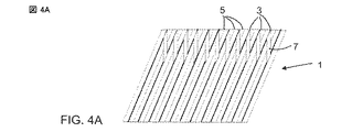
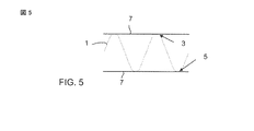
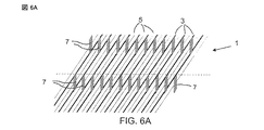
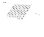
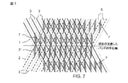
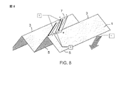
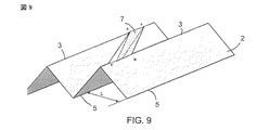
本発明は、複数の図面を参照してその詳細について説明される。図4Aおよび4Bは、この発明によるところの充填材のストリップを上方および下方から見て概略的に示し、図5は、この発明によるところの充填材のストリップを横から見て示し、図6Aおよび6Bは、この発明によるところの充填材のストリップを上方或いは下方から見て概略的に示し、図7は、低い方のストリップの概念を伴って、この発明によるところの充填材の2つの重ね合わせられたストリップを上方から見て示し、図8、9、10は、この発明によるところの充填材のストリップの等角透視図を示す。 The present invention will be described in detail with reference to a plurality of drawings. 4A and 4B schematically show the strip of filler according to the invention from above and below, and FIG. 5 shows the strip of filler according to the invention seen from the side, FIG. 6B schematically shows a strip of filler according to the invention from above or below, and FIG. 7 shows two superpositions of filler according to the invention, with the concept of the lower strip. FIG. 8, 9, 10 shows an isometric view of a strip of filler according to the present invention.
図4Aは、複数の連続したバンドレット7を有するストリップ1を上方から見た図を示す。各バンドレット7は、このストリップの同じ高さで連続した2つの稜部3のみ接続する。
FIG. 4A shows a view from above of the
図4Bは、複数の連続したバンドレット9を有するストリップ1を下方から見た図を示す。各バンドレットは、このストリップの同じ高さで連続した2つの谷部9のみ接続する。
FIG. 4B shows a view from below of the
図4Aおよび4Bは、このストリップが、稜部を連結する一方の連続したバンドレット、および谷部を連結する他方の連続したバンドレットを有するように、組み合わされることができる。2組の連続したバンドレットは、互いに離間されている。 4A and 4B can be combined such that the strip has one continuous bandlet connecting the ridges and the other continuous bandlet connecting the valleys. Two sets of continuous bandlets are spaced apart from each other.
図5は、複数の折部の軸に沿った図を示す。“従来”の波形の交差の形状は、ストリップ1として見ることができる。実際に連続した複数の平らな表面からなるバンドレッド7は、ストリップの複数の稜部3を連結する。実際に連続した複数の平らな表面からなるバンドレット9は、ストリップ1の複数の谷部5を連結する。
FIG. 5 shows a view along the axis of the plurality of folds. The “conventional” corrugated intersection shape can be seen as
図6Aおよび6Bは、図4Aおよび4Bの変形バージョンであり、第2の連続した複数のバンドレットを有する。これら図6Aおよび6Bは、明らかに、組み合わされることができる。 6A and 6B are modified versions of FIGS. 4A and 4B and have a second continuous plurality of bandlets. These FIGS. 6A and 6B can obviously be combined.
図7は、それぞれ、複数の稜部を連結する2つの連続した複数のバンドレット7を有する2つのストリップを示す。複数の稜部のうち連続した2つの稜部の間の距離は、一方のストリップ1の複数のスロットが連続するストリップ2の複数のスロットの上に重ならないように選択される。
FIG. 7 shows two strips each having two
図8は、この発明によるところの充填材ストリップの透視図である。このストリップ1は、通常、少なくとも1つの以下の特性を有する平行六面体ABCDの形でバンドレット7を形成する少なくとも1つの切り抜きを有する。
FIG. 8 is a perspective view of a filler strip according to the present invention. This
・少なくとも1つのエッジAD或いはBCは、規定された(定義が与えられた)最大傾斜のラインから20°より少なく、或いは10°より少ない方向を有する。 At least one edge AD or BC has a direction of less than 20 ° or less than 10 ° from the defined (given definition) maximum slope line.
・一側AB(或いはCD)は、波形の交差した充填材の一部を形成するストリップ1の稜部3(或いは谷部5)にある折れ部である。この一側は、複数のチャネルの傾斜δの角度(通常、45°と60°との間)として、水平に関して同じ傾斜を有する。
One side AB (or CD) is a fold at the ridge 3 (or trough 5) of the
・終り側CDは、切り抜きによって得られたエッジであり、平らな面ABCDがストリップ1の他の要素(例えば、連続した稜部3のみ)に接触するように配置される。 The ending CD is the edge obtained by the cutout and is arranged so that the flat surface ABCD contacts the other elements of the strip 1 (for example only the continuous ridge 3).
液体の分離を発生させることができる端部CD上の液滴の凝集および発生のいかなる現象をも防止するため、ストリップ2のため図8に図示したように、エッジCDが、連続した稜部3から区別がつかない(並べられて且つ接触され)ことが考えられることができる。このため、ABおよびCDを通る直線の距離は、波のピッチLと等しくなければならない。この配置は、明らかに、複数の谷部5に接触する複数のバンドレット9にも適用される。
To prevent any phenomenon of droplet agglomeration and generation on the edge CD that can cause liquid separation, the edge CD has a
代りに、図10に示すように、ストリップ1の稜部3に連結された平らな表面7が、同じストリップの連続する稜部3Aに連結された平らな表面7Aに接触できる。従って、波形の交差した充填材に組み込まれた平らな表面は、2つの平行六面体から形成される。
Instead, as shown in FIG. 10, the
・ABCD(平らな表面7)は、稜部3から区別がつかないサイドABによってストリップ1へ連結される。
ABCD (flat surface 7) is connected to the
・A’B’C’D’(平らな表面7A)は、稜部3Aから区別がつかないサイドC’D’によってストリップ1へ連結される。
A'B'C'D '(
それゆえに、バンドレットは、2つの平らな表面7、7Aからなる。
The bandlet therefore consists of two
1つの小面から他の小面への液体の通過を助長するための要求は、それら表面の1つの部分の重ね合わせや接触を有することである(この実例において、平行四辺形A’B”CD”によって示される)。 A requirement for facilitating the passage of liquid from one facet to another is to have overlap or contact of one part of those surfaces (in this example, a parallelogram A'B " CD ").
図10の形状のため、もはや波の複数の稜部或いは波の複数の谷部で連結されないで、ガス流の遮断を達成するため、複数の側部のあらゆる仰角で、これら2つの平らな表面を生出することが可能である。 Because of the shape of FIG. 10, these two flat surfaces at any elevation angle on multiple sides to achieve gas flow blockage are no longer connected by wave ridges or wave valleys. Can be born.
この発明によるところの複数の充填材モジュールは、もちろん、他の装置を含むことができる。 The plurality of filler modules according to the invention can of course include other devices.
種々の表面処理、例えば:
以下の特許で説明された装置のような、充填材同士の境界における浸水を防止するための装置:
実験に基づくテストは、1つのモジュールから他のモジュールへ通過するため、約90°の角度でガスが方向を変えるように仕向けられた位置において、充填材の浸水が複数のモジュールの間の境界で初めに起きることを立証した。それゆえに、複数のモジュールの中央部分が浸水ポイントにまだ到達しない一方で、カラムの容量が制限される。 Tests based on experiments pass from one module to the other, so that the filler immersion is at the boundary between modules in a position where the gas is directed to change direction at an angle of about 90 °. Proven to get up first. Therefore, the column capacity is limited while the central part of the modules has not yet reached the inundation point.
この現象は、境界の近くで複数のモジュールの底部分における液体の浸水によって分析される:方向の変化点でガスによって担わされる圧力損失は、隣接した領域における液体の凝集を生じる。この液体の凝集は、カラムの時期尚早の浸水を生じる。 This phenomenon is analyzed by liquid immersion in the bottom part of the modules near the boundary: the pressure loss carried by the gas at the change of direction results in liquid agglomeration in adjacent areas. This liquid agglomeration results in premature flooding of the column.
この発明は、より良い機能を有する波形の交差した充填材の安価な製造を可能にする。それゆえに、従来の波形の交差した充填材(スロットを持たない)に使用されたものと同じ質の金属がより効果的充填材を製造するために使用されることから、効率をロスすることなく与えられた流量の処理のために使用される充填材の容積を減少することが可能である。空気の極低温の蒸留に関連して使用されると、カラムのサイズおよびコールドボックスのサイズを減少することができる。 This invention allows for the inexpensive production of corrugated crossed fillers with better function. Therefore, without loss of efficiency, the same quality metal used for conventional corrugated cross fillers (without slots) is used to produce more effective fillers. It is possible to reduce the volume of filler used for the treatment of a given flow rate. When used in connection with cryogenic distillation of air, the column size and cold box size can be reduced.
この発明は、蒸留カラムにおける投資の減少を可能にする。 This invention allows for a reduction in investment in the distillation column.
Claims (10)
少なくとも1つのバンドレット(7;7、7A;9)と、を有し、
上記各ストリップが、波形にされ、一般的に矩形であり、上記複数のストリップを横切る複数の波形が、隣接するストリップの波形に対して50°から100°の間で指向されるように、上記複数のストリップが、互いに対向して配置され、波形の交差した構造を形成し、
上記バンドレットが、上記ストリップの少なくとも1つの第1稜部(3、5)、および上記ストリップの少なくとも1つの第2稜部で同時に接触し、上記第2稜部が上記第1稜部に隣接し、
上記バンドレットが、上記波形にスロットを残すような上記ストリップの切り抜きであることを特徴とする、材料交換および/或いは熱交換カラムのためにデザインされた定型の充填材要素。 A plurality of alternating strips (1, 2);
And at least one bandlet (7; 7, 7A; 9),
Each of the strips is corrugated and generally rectangular, and the plurality of corrugations across the plurality of strips are oriented between 50 ° and 100 ° relative to the corrugations of adjacent strips. A plurality of strips are arranged opposite each other to form a corrugated crossing structure
The bandlet simultaneously contacts at least one first ridge (3, 5) of the strip and at least one second ridge of the strip, and the second ridge is adjacent to the first ridge. And
A regular packing element designed for material exchange and / or heat exchange columns, characterized in that the bandlet is a cutout of the strip leaving a slot in the corrugation.
Applications Claiming Priority (3)
| Application Number | Priority Date | Filing Date | Title |
|---|---|---|---|
| FR0857962A FR2938776A1 (en) | 2008-11-24 | 2008-11-24 | CROSS-CROSSOVER TRIM AND COLUMN INCORPORATING SUCH A TRIM |
| FR0857962 | 2008-11-24 | ||
| PCT/FR2009/052187 WO2010058115A1 (en) | 2008-11-24 | 2009-11-16 | Corrugated criss-crossing packing and column including such a packing |
Publications (1)
| Publication Number | Publication Date |
|---|---|
| JP2012509757A true JP2012509757A (en) | 2012-04-26 |
Family
ID=40934138
Family Applications (1)
| Application Number | Title | Priority Date | Filing Date |
|---|---|---|---|
| JP2011536924A Withdrawn JP2012509757A (en) | 2008-11-24 | 2009-11-16 | Corrugated packing material and column packed with this packing material |
Country Status (6)
| Country | Link |
|---|---|
| US (1) | US20110226360A1 (en) |
| EP (1) | EP2367626A1 (en) |
| JP (1) | JP2012509757A (en) |
| CN (1) | CN102223949A (en) |
| FR (1) | FR2938776A1 (en) |
| WO (1) | WO2010058115A1 (en) |
Families Citing this family (4)
| Publication number | Priority date | Publication date | Assignee | Title |
|---|---|---|---|---|
| US10953382B2 (en) * | 2017-06-09 | 2021-03-23 | Koch-Glitsch, Lp | Structured packing module for mass transfer columns |
| CN107673467A (en) * | 2017-10-11 | 2018-02-09 | 上海市政工程设计研究总院(集团)有限公司 | A kind of the Biological Pretreatment reactor and method of the micro- reoxygenation in surface |
| EP3808447A1 (en) * | 2019-10-14 | 2021-04-21 | Sulzer Management AG | Plant and process for efficiently producing a structured cross-channel packing element |
| EP4119222B1 (en) | 2021-07-13 | 2025-05-07 | Koch Engineered Solutions GmbH | Structured packing for gas phase reactor |
Family Cites Families (19)
| Publication number | Priority date | Publication date | Assignee | Title |
|---|---|---|---|---|
| CH398503A (en) | 1962-07-31 | 1966-03-15 | Sulzer Ag | Mass transfer column |
| AT321865B (en) * | 1970-04-27 | 1975-04-25 | Dl Veb Maschinen Und Appbau Gr | HIGH PERFORMANCE SA EXCHANGE PACK FOR COLUMNS |
| CH608380A5 (en) | 1976-01-16 | 1979-01-15 | Sulzer Ag | Packing body in rectifying columns |
| CH617357A5 (en) * | 1977-05-12 | 1980-05-30 | Sulzer Ag | |
| US4604247A (en) * | 1983-06-21 | 1986-08-05 | Glitsch, Inc. | Tower packing material and method |
| CH662515A5 (en) * | 1983-12-15 | 1987-10-15 | Sulzer Ag | Built-in element for mass transfer columns |
| DE3414267A1 (en) * | 1984-04-14 | 1985-11-07 | Raschig Gmbh, 6700 Ludwigshafen | INSTALLATION ELEMENT FOR TUBE OR HEAT EXCHANGE COLUMN |
| CH664091A5 (en) * | 1985-01-30 | 1988-02-15 | Sulzer Ag | PACKING BODY MADE OF THIN, FILM-LIKE MATERIAL FOR FABRIC AND HEAT EXCHANGE COLUMNS BETWEEN LIQUID AND GASEOUS PHASES. |
| US4670196A (en) * | 1985-09-05 | 1987-06-02 | Norton Company | Tower packing element |
| US4710326A (en) * | 1986-08-29 | 1987-12-01 | Seah Alexander M | Corrugated packing and methods of use |
| US4740334A (en) * | 1987-05-29 | 1988-04-26 | Norton Company | Tower packing element with embossed surfaces |
| US5013492A (en) * | 1990-04-06 | 1991-05-07 | Munters Corporation | Arrangement for contact bodies for liquid and gas |
| US5057250A (en) * | 1990-11-27 | 1991-10-15 | Glitsch, Inc. | Tower packing with small louvers |
| US5407607A (en) * | 1993-11-09 | 1995-04-18 | Mix; Thomas W. | Structured packing elements |
| US5510170A (en) * | 1994-03-25 | 1996-04-23 | Norton Chemical Process Products Corp. | Securing packing elements |
| CN1091646C (en) * | 1994-10-04 | 2002-10-02 | 普莱克斯技术有限公司 | Structured packing with improved capacity for rectification systems |
| ATE192353T1 (en) * | 1995-08-24 | 2000-05-15 | Raschig Gmbh | BUILT-IN ELEMENT FOR MATERIAL OR HEAT EXCHANGE COLUMNS |
| US6509082B1 (en) * | 1999-06-25 | 2003-01-21 | The Boc Group, Inc. | Structured packing |
| US6751986B2 (en) * | 2000-12-22 | 2004-06-22 | The Bog Group, Inc. | Structured packing |
-
2008
- 2008-11-24 FR FR0857962A patent/FR2938776A1/en not_active Withdrawn
-
2009
- 2009-11-16 WO PCT/FR2009/052187 patent/WO2010058115A1/en not_active Ceased
- 2009-11-16 JP JP2011536924A patent/JP2012509757A/en not_active Withdrawn
- 2009-11-16 EP EP09768194A patent/EP2367626A1/en not_active Withdrawn
- 2009-11-16 CN CN200980146910.8A patent/CN102223949A/en active Pending
- 2009-11-16 US US13/130,871 patent/US20110226360A1/en not_active Abandoned
Also Published As
| Publication number | Publication date |
|---|---|
| EP2367626A1 (en) | 2011-09-28 |
| CN102223949A (en) | 2011-10-19 |
| FR2938776A1 (en) | 2010-05-28 |
| WO2010058115A1 (en) | 2010-05-27 |
| US20110226360A1 (en) | 2011-09-22 |
Similar Documents
| Publication | Publication Date | Title |
|---|---|---|
| KR100359536B1 (en) | Film fill-pack for inducement of spiraling gas flow in heat and mass transfer contact apparatus with self-spacing fill-sheets | |
| US10048020B2 (en) | Heat transfer surfaces with flanged apertures | |
| JP4958184B2 (en) | Heat exchanger | |
| US20070012430A1 (en) | Heat exchangers with corrugated heat exchange elements of improved strength | |
| US10677538B2 (en) | Indirect heat exchanger | |
| US7059397B2 (en) | Heat exchanger with brazed plates | |
| JP2020523183A (en) | Structured packing material module for mass transfer columns | |
| CN115475595A (en) | Filling sheet and related filling package assembly | |
| CN101341372A (en) | A new corrugated heat exchanger and its application | |
| JP7728364B2 (en) | Structured packing material and cross-flow contactor employing the same | |
| JP6206975B2 (en) | Heat exchanger | |
| JP5834324B2 (en) | Corrugated fin heat exchanger | |
| JP4065432B2 (en) | Heat exchange plate | |
| KR100338718B1 (en) | Film fill-pack for inducement of spiraling gas flow in heat and mass transfer contact apparatus with self-spacing fill-sheets | |
| US4276242A (en) | Vapor-liquid contact grid apparatus | |
| US20110226360A1 (en) | Corrugated Criss-Crossing Packing And Column Including Such A Packing | |
| CN108253833B (en) | Fin component for heat exchanger and the heat exchanger with the fin component | |
| JP4625075B2 (en) | Distillation column | |
| JP2005511284A (en) | Strips for packing modules, corresponding modules and columns | |
| JPH09280761A (en) | Heat exchanger with a stack of heat transfer element plates | |
| JP4634033B2 (en) | Strip for packing module, corresponding module and equipment | |
| US4427606A (en) | Vapor-liquid contact grid | |
| RU171603U1 (en) | REGULAR NOZZLE FOR HEAT AND MASS TRANSFER APPARATUS | |
| JP3309285B2 (en) | Packing material for mass exchange and / or heat exchange tower | |
| CA2512318A1 (en) | Heat exchangers with corrugated heat exchange elements of improved strength |
Legal Events
| Date | Code | Title | Description |
|---|---|---|---|
| A300 | Application deemed to be withdrawn because no request for examination was validly filed |
Free format text: JAPANESE INTERMEDIATE CODE: A300 Effective date: 20130205 |