JP2012509794A - Printing unit with curved sealed doctor blade - Google Patents
Printing unit with curved sealed doctor blade Download PDFInfo
- Publication number
- JP2012509794A JP2012509794A JP2011537846A JP2011537846A JP2012509794A JP 2012509794 A JP2012509794 A JP 2012509794A JP 2011537846 A JP2011537846 A JP 2011537846A JP 2011537846 A JP2011537846 A JP 2011537846A JP 2012509794 A JP2012509794 A JP 2012509794A
- Authority
- JP
- Japan
- Prior art keywords
- doctor blade
- holder
- rotating roller
- contact area
- curve
- Prior art date
- Legal status (The legal status is an assumption and is not a legal conclusion. Google has not performed a legal analysis and makes no representation as to the accuracy of the status listed.)
- Pending
Links
- 238000007639 printing Methods 0.000 title claims abstract description 21
- 238000012856 packing Methods 0.000 claims abstract description 38
- 238000007789 sealing Methods 0.000 claims description 10
- 230000007423 decrease Effects 0.000 claims description 7
- 230000001154 acute effect Effects 0.000 claims description 4
- 230000007246 mechanism Effects 0.000 claims description 4
- 229910000831 Steel Inorganic materials 0.000 description 10
- 239000010959 steel Substances 0.000 description 10
- 239000000463 material Substances 0.000 description 3
- 230000007704 transition Effects 0.000 description 3
- 230000006872 improvement Effects 0.000 description 2
- 230000009471 action Effects 0.000 description 1
- 238000013459 approach Methods 0.000 description 1
- 238000005452 bending Methods 0.000 description 1
- 230000015572 biosynthetic process Effects 0.000 description 1
- 230000000903 blocking effect Effects 0.000 description 1
- 230000005489 elastic deformation Effects 0.000 description 1
- 239000000835 fiber Substances 0.000 description 1
- 239000012528 membrane Substances 0.000 description 1
- 238000000034 method Methods 0.000 description 1
- 229920000642 polymer Polymers 0.000 description 1
- 230000008569 process Effects 0.000 description 1
- 230000002787 reinforcement Effects 0.000 description 1
- 238000007790 scraping Methods 0.000 description 1
Images






Classifications
-
- B—PERFORMING OPERATIONS; TRANSPORTING
- B41—PRINTING; LINING MACHINES; TYPEWRITERS; STAMPS
- B41F—PRINTING MACHINES OR PRESSES
- B41F31/00—Inking arrangements or devices
- B41F31/02—Ducts, containers, supply or metering devices
- B41F31/027—Ink rail devices for inking ink rollers
Landscapes
- Inking, Control Or Cleaning Of Printing Machines (AREA)
- Sealing With Elastic Sealing Lips (AREA)
Abstract
回転ローラと、ホルダ(6)から回転ローラの表面上の接線方向接触ポイントまで曲率減少曲線として延在する弾性密封ドクターブレード(2)を備えるインク室とを有する印刷ユニット。密封ドクターブレードとインク室との間を密封するため、パッキンは曲率に追従している。
【選択図】 図4A printing unit comprising a rotating roller and an ink chamber comprising an elastic sealed doctor blade (2) extending as a curvature-decreasing curve from a holder (6) to a tangential contact point on the surface of the rotating roller. In order to seal between the sealed doctor blade and the ink chamber, the packing follows the curvature.
[Selection] Figure 4
Description
本発明は、回転ローラと、接触エリアにおいて回転ローラの表面との接触状態にある密封ドクターブレードを備えるインク室とから成る印刷ユニットに関し、密封ドクターブレードはホルダに固定されて、ホルダと接触エリアとの間で曲線状に弾性変形される。 The present invention relates to a printing unit comprising a rotating roller and an ink chamber having a sealed doctor blade that is in contact with the surface of the rotating roller in the contact area, the sealed doctor blade being fixed to the holder, and the holder and the contact area. It is elastically deformed in a curved line between.
特許文献1には、図1に描かれたドクターブレード装置が開示されている。この装置は、室3の中のインクと接触するスクリーンローラ(不図示)を備える印刷ユニットのためのインクを作業中に収容する、底面3Aと側面3Bおよび3Cとを備えるU字形ドクターブレード室3を有する室バーを含む。スクリーンローラに対する密封機能を有するレール5,6により、2本のドクターブレード1,2が室3にクランプされ、その表面は室3の中のインクと接触している。インクは、通路8を介して室3へ案内される。室3の各小室に1本ずつ2本の通路8が示されており、室の内側のパッキン4と室の端部のパッキン4とを境界とすることにより小室が設けられている。パッキン4は、スクリーンローラと当接するため凹形4Aを有する。
特許文献2からのコピーである図2には、このタイプのパッキンが再び示されている。このパッキンは、密封強化用にスクリーンローラと当接するための硬質材料製のレール7を備える中央部10を有する。ドクターブレードはさらに、いくつかの直線状エラストマリップ9によっても支持されている。これらのエラストマリップ9は従来、概ね直線状で、スクリーンローラに対するドクターブレードの接触角度にほぼ対応する角度を持つ。
This type of packing is again shown in FIG. 2, which is a copy from US Pat. This packing has a
図1に描かれた2本のドクターブレード1,2は、異なる機能を有する。第1ドクターブレード1はローラの回転方向と反対を向いたエッジを有し、回転中に余分なインクをローラから削り取る正方向ドクターブレードまたは能動的ドクターブレードと呼ばれ、室2を通過したローラ上のスクリーンにはインクが充填されている。回転方向と同じ方向を向いたエッジを有する第2ドクターブレード2は、インクが室3から漏出しないように密封するという主な機能を有する受動的ドクターブレードまたは密封ドクターブレードと呼ばれる。
The two
120m/分以上、または200m/分以上の速度など高い速度でスクリーンローラが回転する印刷プロセス中には、すべてのインクが付着するわけではなく、回転ローラによってインクが一周分運ばれる。このインクは、密封ドクターブレードの外側で収集される傾向を持つ。一般的に0.3mmの厚さで使用されるドクターブレードは、インクを再び室まで運ぶのに充分なほどの可撓性を備えていない。 During the printing process in which the screen roller rotates at a high speed such as a speed of 120 m / min or higher, or a speed of 200 m / min or higher, not all of the ink adheres and the rotary roller carries the ink for one round. This ink tends to be collected outside the sealed doctor blade. The doctor blade, which is typically used with a thickness of 0.3 mm, is not flexible enough to carry the ink back to the chamber.
そのため、曲線に変形されるように約0.10mmの厚さの薄い密封ドクターブレードを使用することが試みられており、その場合に、ドクターブレードのエッジは回転ローラの接線と狭い角度で接触するか、この接線と平行に配置されることもある。この問題は、曲線状密封ドクターブレードも示されている特許文献3に記されている。 Therefore, it has been attempted to use a thin sealed doctor blade with a thickness of about 0.10 mm so as to be deformed into a curve, in which case the edge of the doctor blade contacts the tangent of the rotating roller at a narrow angle. Or it may be arranged parallel to this tangent. This problem is described in U.S. Pat. No. 6,057,097, where a curved sealed doctor blade is also shown.
密封ドクターブレードのこのような変形は、図2に示されているように直線状エッジ9を有する場合に密封ドクターブレードが上記のパッキン4ともはや接触しないことを意味する。
Such a variant of the sealed doctor blade means that the sealed doctor blade no longer contacts the
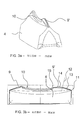
この短所を回避するため、市販の製品では、図3aおよび3bに示されているような別の形状にパッキン4が変形され、レール7を備える中央部に連続して、中央部10の各端部には第1直線状エラストマリップ9と第2曲線状エラストマリップ9’とが設けられている。第2リップ9’は中央部10に向かって曲線状で、移行ポイント15において、密封ドクターブレードと回転ローラとの接線方向接触を助けるため、スクリーンローラに対して接線方向を持つ。リップ9’の曲率は、密封ドクターブレードがホルダから離れる外側エッジ11から中央部10の方向へ増加する。補助線12を参照すると、リップ9’の第1半分13よりもリップ9’の第2半分14の方で曲率が大きくなるように曲率が実際に変化していることが分かる。他の先行技術に対するこの改良にも関わらず、密封ドクターブレードの間に連続的で正確な密封を設けることが可能ではなかった。
In order to avoid this disadvantage, in the commercially available product, the
先行技術による印刷ローラの他の説明では、回転ローラとほぼ接線方向に接触する曲線状経路を持つ密封であることも指摘されている。特許文献4などを参照すること。
Other descriptions of printing rollers according to the prior art also point to a seal with a curved path that contacts the rotating roller in a substantially tangential direction. See
しかし先行技術では、観察される漏出が回避されるように上述の市販パッキンを設計することに関する解決法が開示または指摘されていない。概して、最適形状を持つには密封ドクターブレードがどのようなラインを描くかについての説明が見られない。そのため、これに関するさらなる改良の必要性が存在する。 However, the prior art does not disclose or point out a solution for designing the above-mentioned commercial packing such that observed leakage is avoided. In general, there is no explanation of what line the sealed doctor blade will draw to have the optimal shape. There is therefore a need for further improvements in this regard.
回転ローラと、可能な限り最良のパッキンとの密封を保証するコースを密封ドクターブレードが有するドクターブレード室とを備える印刷ユニットを提供することが、本発明の目的である。さらに、密封ドクターブレードと室との間にパッキンを設けて、密封ドクターブレードと相互作用を行う室が可能な限り最良の密封を目的として設計されることが目的である。 It is an object of the present invention to provide a printing unit comprising a rotating roller and a doctor blade chamber in which the sealed doctor blade has a course that guarantees the sealing of the best possible packing. A further object is to provide a packing between the sealed doctor blade and the chamber so that the chamber interacting with the sealed doctor blade is designed for the best possible sealing.
この目的は、回転ローラと、接触エリアにおいて回転ローラの表面との接触状態にある密封ドクターブレードを備えるインク室とを有する後述の印刷ユニットによって達成される。密封ドクターブレードはホルダに固定されて、ホルダと接触エリアとの間で曲線状に弾性変形され、この変形曲線は、回転ローラとの接触エリアよりもホルダの方で大きい曲率を有する。例えば曲線は、ホルダに隣接する第1半分と、第1半分よりも曲率が大きな回転ローラと隣接する第2半分とを有する。 This object is achieved by a printing unit described below having a rotating roller and an ink chamber with a sealed doctor blade in contact with the surface of the rotating roller in the contact area. The sealed doctor blade is fixed to the holder and elastically deformed in a curved shape between the holder and the contact area, and this deformation curve has a larger curvature in the holder than in the contact area with the rotating roller. For example, the curve has a first half adjacent to the holder and a second half adjacent to a rotating roller having a greater curvature than the first half.
曲線の曲率はホルダから接触エリアまで、増加することなく減少する、好ましくは均一に減少するように、導入部で説明された図3のパッキンの曲率が調整されると、さらに良好な密封が達成されると思われる。この問題を集中的に検討したところ、導入部で説明された図3のパッキンの密封ドクターブレードがパッキンの曲率に追従しなくなる程度まで強制変形されることが明らかとなった。しかし、曲率が直線状またはほぼ直線状に減少する場合には特に、ホルダから減少するような曲率形状によれば、はるかに良好な方法で密封ドクターブレードがパッキンの曲率に合わせて調整される。 Even better sealing is achieved when the curvature of the packing of FIG. 3 described in the introduction is adjusted so that the curvature of the curve decreases without increasing, preferably evenly, from the holder to the contact area. It seems to be done. As a result of intensive examination of this problem, it was found that the sealed doctor blade of the packing shown in FIG. 3 described in the introduction section was forcibly deformed to the extent that it did not follow the curvature of the packing. However, especially when the curvature decreases linearly or nearly linearly, the curvature shape that decreases from the holder adjusts the sealed doctor blade to the curvature of the packing in a much better manner.
このようにして、インク室の全長にわたって均一な曲線形状を密封ドクターブレードが確実に有する。さらに、新規の調整パッキンによりこの形状が維持される。 In this way, the sealed doctor blade reliably has a uniform curved shape over the entire length of the ink chamber. Furthermore, this shape is maintained by a new adjustment packing.
一般的に、接触エリアにおける回転ローラの接線に対して鋭角、例えば30度で配置されたホルダに密封ドクターブレードが固定される。この角度は、好ましくは5と50度の間、好ましくは15と40度の間、最も好ましくは20と35度の間である。密封ドクターブレードはホルダから回転ローラへ曲線状であって、ここで0と10度の間、好ましくは0と5度の間などの非常に小さな角度で、実際にはほぼ接線方向に回転ローラとの接触状態にある。こうして、回転ローラ、例えばスクリーンローラにおけるインク残留物が密封ドクターブレードを越えて回転してインク室に再び入る。こうして、回転中に密封ドクターブレードがインクを削り取って室へ戻らないようにするブレード阻止作用が回避される。 Generally, the sealed doctor blade is fixed to a holder that is arranged at an acute angle, for example, 30 degrees, with respect to the tangent to the rotating roller in the contact area. This angle is preferably between 5 and 50 degrees, preferably between 15 and 40 degrees, most preferably between 20 and 35 degrees. The sealed doctor blade is curvilinear from the holder to the rotating roller, where it is in a very small angle, such as between 0 and 10 degrees, preferably between 0 and 5 degrees, and in fact almost tangentially with the rotating roller. In contact. Thus, the ink residue on the rotating roller, eg, the screen roller, rotates past the sealed doctor blade and reenters the ink chamber. Thus, the blade blocking action that prevents the sealed doctor blade from scraping ink back into the chamber during rotation is avoided.
回転ローラにおいて密封ドクターブレードが接線方向または略接線方向のコースを持つという長所、すなわち120m/分以上を意味する比較的高速で回転することにより、回転ローラと密封ドクターブレードとの間にインク膜が形成されて密封ドクターブレードが実際には回転ローラと接触しないという事実が観察されている。この現象は、ハイドロプレーニングと類似している。これは、密封ドクターブレードと回転ローラとの間の摩擦が非常にわずかで、磨耗をかなり軽減することを意味する。インク膜の形成によって密封ドクターブレードと回転ローラとの間に直接的な接触が設けられないにも関わらず、「接触エリア」という表現が用いられ、密封ドクターブレードと回転ローラとの間の間隙が最小であるエリアとして理解されるべきである。 By rotating at a relatively high speed, which means that the sealed doctor blade has a tangential or substantially tangential course in the rotating roller, that is, 120 m / min or more, an ink film is formed between the rotating roller and the sealed doctor blade. It has been observed that the formed and sealed doctor blade does not actually contact the rotating roller. This phenomenon is similar to hydroplaning. This means that there is very little friction between the sealed doctor blade and the rotating roller, which significantly reduces wear. Despite the fact that the ink film formation does not provide direct contact between the sealed doctor blade and the rotating roller, the expression “contact area” is used and the gap between the sealed doctor blade and the rotating roller is It should be understood as the area that is the smallest.
ホルダのドクターブレードが接線に対してかなりの角度、例えば30°に配置される場合には、ドクターブレードが比較的容易に撓曲しなければならない。一般的に使用されるタイプの鋼により、この場合の厚さは0.04mmと0.15mmの間であることが好ましく、ホルダから接触エリアまで25mmと50mmの間の距離にわたって曲線を描いている。 If the doctor blade of the holder is arranged at a considerable angle relative to the tangent, for example 30 °, the doctor blade must bend relatively easily. Depending on the commonly used type of steel, the thickness in this case is preferably between 0.04 mm and 0.15 mm and is curved over a distance between 25 mm and 50 mm from the holder to the contact area .
0.3mmの厚さを持つ先行技術のドクターブレードにより、30mmにわたって30°の屈曲を得ることは実際的には可能でない。このような屈曲を与えるのに必要な回転ローラからの力は、ローラの表面を傷付け、ドクターブレードが破損する危険がある。そのため、10mmを超える材料厚さのドクターブレードを使用することにより、ホルダの角度が30°未満、好ましくは20°未満であることが好ましい。そしてドクターブレードの厚さが0.15mm以上である場合には、ホルダの角度が15°未満であることが好ましい。 It is not practically possible to obtain a 30 ° bend over 30 mm with a prior art doctor blade with a thickness of 0.3 mm. The force from the rotating roller necessary to provide such bending can damage the surface of the roller and damage the doctor blade. Therefore, it is preferable that the angle of the holder is less than 30 °, preferably less than 20 °, by using a doctor blade having a material thickness exceeding 10 mm. And when the thickness of a doctor blade is 0.15 mm or more, it is preferable that the angle of a holder is less than 15 degrees.
実用的な実施形態において、密封ドクターブレードのホルダは、インク室に設けられたレール機構である。曲線状密封ドクターブレードと室の底面との間を密封するため、パッキンが使用される。この時、パッキンは、回転ローラと接触するための曲線状中央部と、ホルダから接触エリアまで密封ドクターブレードを支持するための中央パッキンと連続したリップとを有する。リップは、上記のように密封ドクターブレードの曲率に追従する曲線を持つように設計されている。 In a practical embodiment, the holder of the sealed doctor blade is a rail mechanism provided in the ink chamber. A packing is used to seal between the curved sealing doctor blade and the bottom of the chamber. At this time, the packing has a curvilinear central portion for contacting the rotating roller, and a lip continuous with the central packing for supporting the sealed doctor blade from the holder to the contact area. The lip is designed to have a curve that follows the curvature of the sealed doctor blade as described above.
例えば、密封ドクターブレードは、ホルダと隣接する第1半分と、中央部と連続する第2半分とを備える曲線を有し、曲率は第1半分において最大である。この時、回転ローラとの接触エリアよりもホルダの方で曲率が大きい。中央部から離間する方向に増加する曲率を持つ曲線を備えるようにリップを設計することで、曲率が減少する従来のパッキンよりも良好な密封が達成される。曲率は、中央部から均一に、例えば直線状またはほぼ直線状に増加することが好ましい。 For example, the sealed doctor blade has a curve with a first half adjacent to the holder and a second half continuous with the center, and the curvature is maximum in the first half. At this time, the curvature is larger in the holder than in the contact area with the rotating roller. By designing the lip to have a curve with a curvature that increases in a direction away from the center, a better seal is achieved than a conventional packing with a reduced curvature. It is preferable that the curvature increases uniformly from the central portion, for example, linearly or substantially linearly.
図面を参照して、本発明をさらに詳細に説明する。
図1,2,3は、導入部で説明された先行技術によるドクターブレード室およびパッキンを示す。 1, 2 and 3 show the doctor blade chamber and packing according to the prior art described in the introduction.
図4は、本発明による印刷ユニットを示す。印刷ユニットは、回転ローラ18、好ましくは、回転により回転ローラ18に吸収されるインクを空洞19に収容するドクターブレード室3との接触状態で、図によれば時計方向に回転するスクリーンローラを含む。
FIG. 4 shows a printing unit according to the invention. The printing unit includes a
レール機構17により室3に固定された能動的ドクターブレード1は、回転ローラ18から余分なインクを削り取る。このインクは、完成プリントが紙に転写される前に別のローラ20に転写される。能動的ドクターブレード1は、接触ポイント24において接線23と角度vでホルダ17[16]に固定されている。この角度vは一般的に30〜35°である。
The
他のローラ20に転写されなかったインクは、密封ドクターブレード2と回転ローラ18との間の空洞21に運ばれる。接触エリア22の密封ドクターブレード2は回転ローラ18に対して接線方向またはほぼ接線方向であるので、余分なインクがドクターブレード室3の空洞19に容易に引き込まれる。こうして密封ドクターブレード2と回転ローラ18との間に膜が形成されて、摩擦を軽減するとともに、密封ドクターブレード2ばかりでなく回転ローラ18での密封による磨耗を減少させる。
The ink that has not been transferred to the
密封ドクターブレード2と回転ローラ18との間の接線方向の接触は、密封ドクターブレード2の弾性変形によって達成される。接触エリア22よりもホルダ16の方で大きい曲率で、密封ドクターブレード2がホルダ6から曲線を描く。補助線12は、ホルダ16と接触エリアとの間の密封ドクターブレード2の長さを二つの部分に分割し、第1半分13’の曲率は第2半分14’のものよりも大きいことが図から理解できる。
Tangential contact between the sealed
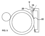
図5には、密封ドクターブレード2の接触エリア22における接線25とホルダ16との間の角度wが図示されている。例示のため、図の角度wは、現実の一般値よりも大きくなっている。この鋭角は原則として5と50度の間の値を取るが、一般的には20と35度の間であろう。密封ドクターブレードの弾性定数および厚さの値により、過剰圧力ゆえに回転ローラに損傷を与えることなくどれほど変形が可能であるかが制限されるので、撓曲はこの弾性定数および厚さに左右される。ドクターブレードが厚くなると、薄いドクターブレードの場合よりも角度が小さくなる。回転ローラに対する密封ドクターブレードの圧力は、密封ドクターブレードと回転ローラとの間にインク膜が形成可能である条件に合わせて調整される。この膜は、密封ドクターブレードの長さに沿って数ミリメートル延在し、回転ローラに沿った直線状接触エリアというよりは拡張接触エリアのようなものである。
FIG. 5 shows the angle w between the
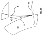
図6aは、ドクターブレード室と回転ローラ18の一部とを示し、円内の詳細Aが図6bに拡大図で再度示されている。所与の屈曲により、密封ドクターブレード2のエッジ26は回転ローラと直線上で接する。しかし作業中に、密封ドクターブレード2と回転ローラ18との間を通過することで室3に運ばれたインクにより、密封ドクターブレードが回転ローラから持ち上げられる。そのため、直線状接触エリア22は作業中に、数ミリメートルにわたって延在する接触エリアに変化する。インク膜とのこの接触エリアが密封ドクターブレード2のエッジ26に位置するように、一般的に密封ドクターブレードが回転ローラに対して調節される。しかし、摩擦により減少するインク膜が作業中に密封ドクターブレードと回転ローラとの間に形成される限り、密封ドクターブレードと回転ローラとの間の接触ラインが密封ドクターブレード2のエッジ26にあるか、または密封ドクターブレード内のある距離にあるか、つまり密封ドクターブレードが理論的接触ラインを越えているかどうかについて大きな相違はないと思われるので、この調節は厳密には必要でない。
FIG. 6a shows the doctor blade chamber and part of the
図面において、接触エリア22における接線25と密封ドクターブレード2との間の角度は、ゼロ度より大きい。インクが容易に密封ドクターブレード2を通過して室3へ戻るように、この角度は一般的に0と5度の間に維持される。
In the drawing, the angle between the
図7は、図4のような室に用いるパッキンの概略図である。図7aは側面図であるのに対して図7bは斜視図でパッキンを示す。パッキン4は、回転ローラと当接するためのレール7を備える中央部10が設けられた弾性ソケット26を有する。レールは、回転ローラへの加圧状態でローラの曲率に対応する曲率を有する。パッキンが回転ローラに押圧されて若干変形した時に回転ローラの曲率に追従するように、レールは調整されている。この圧力によってパッキンは一般的に二分の一ミリメートル圧縮され、そのため、パッキンが回転ローラに押圧される時に回転ローラと全く同じ曲率が必ずしもレールに設けられるわけではない。
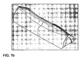
FIG. 7 is a schematic view of the packing used in the chamber as shown in FIG. FIG. 7a is a side view whereas FIG. 7b is a perspective view showing the packing. The
中央部10の各端部から延出するように、第1直線状エラストマリップ9と第2曲線状エラストマリップ9”とが設けられている。第2リップ9”は中央部10に向かって曲線を描き、回転ローラに対する密封ドクターブレードの接線方向接触を助けるため、移行ポイント15では回転ローラに対して接線方向を有する。リップ9”の曲率は中央部10から外側エッジ11に向かって増加し、ここで密封ドクターブレードはホルダと離れる。補助線12を参照すると、リップ9’の第2半分14よりもリップ9’の第1半分13の方で曲率が大きくなるように曲率が実際に変化していることが分かる。このコースは、密封ドクターブレードに対して先行技術システムよりもはるかに良好な密封を保証する。
A first linear
密封ドクターブレードは、繊維補強材などを含むポリマーで製作される。しかし多くの場合、ドクターブレード鋼が使用される。ドクターブレード鋼は一般的に、コイルに巻かれた長いウェブ状で、一般的に35または50mmの幅を持つものとして設けられる。ドクターブレード鋼は弾性ナイフ鋼で製作され、非装填時には平坦である。このような50mm幅のドクターブレード鋼が、最初の15mmだけホルダに押し込まれ、図1にも示されているようにレールがドクターブレード鋼を室に押圧する。こうして、ドクターブレード鋼の自由エッジが回転ローラ18に押圧される時、ホルダの外側に突出している35mmは曲線状である。密封ドクターブレード2の自由エッジは、接触エリアでの接線と好ましくは5度未満、最も好ましくは2度未満の角度で、接線方向または略接線方向において回転ローラ18に追従することが好ましい。次に、回転ローラと密封ドクターブレードのエッジエリアとの間には、密封ドクターブレードのエッジから数ミリメートル、一般的には2と5mmの間に延在するインク膜が形成される。
The sealed doctor blade is made of a polymer that includes fiber reinforcement and the like. However, in many cases doctor blade steel is used. Doctor blade steel is typically provided as a long web wound around a coil, typically having a width of 35 or 50 mm. Doctor blade steel is made of elastic knife steel and is flat when unloaded. Such a 50 mm wide doctor blade steel is pushed into the holder by the first 15 mm, and the rail presses the doctor blade steel into the chamber as also shown in FIG. Thus, when the free edge of the doctor blade steel is pressed against the rotating
図8は、0.1mmの厚さのドクターブレードについて好適な曲線を示す。横座標はホルダからのドクターブレードの距離を指し、縦座標は7mmのエッジの撓曲および曲線の好適なコースを指す。曲線は実質的には、u(x)=k1−k2x+k3x3のようなラインを描く。定数については、ドクターブレードのエッジへの回転ローラからの力、材料の弾性定数、および慣性モーメントで一部が形成される。示された曲線のコースでは、曲線関数の二次導関数である曲率は、ホルダからの距離により直線状に減少する。 FIG. 8 shows a preferred curve for a doctor blade with a thickness of 0.1 mm. The abscissa refers to the distance of the doctor blade from the holder and the ordinate refers to the preferred course of the 7 mm edge flexure and curve. The curve substantially draws a line such as u (x) = k 1 −k 2 x + k 3 x 3 . As for the constant, a part is formed by the force from the rotating roller to the edge of the doctor blade, the elastic constant of the material, and the moment of inertia. In the course of the curve shown, the curvature, which is the second derivative of the curve function, decreases linearly with distance from the holder.
図の曲線は、ドクターブレードのホルダから距離L=30mmにおける23.4Nの力の作用による0.1mm厚さのドクターブレードの7mm撓曲によって、理論的に計算される。ドクターブレードのホルダから距離xにおける曲線のコースは、u(x)=−K*[(L−x)/L−(L−x)3/3L3]に近づく。こうするとK=P*I2/2EによってKが求められ、Pは力、Iは慣性モーメント、Eは弾性係数であって、鋼の場合には一般的に210000/mm2である。 The curve in the figure is theoretically calculated by the 7 mm deflection of a 0.1 mm thick doctor blade due to the action of a 23.4 N force at a distance L = 30 mm from the doctor blade holder. The course of the curve at a distance x from the doctor blade holder approaches u (x) = − K * [(L−x) / L− (L−x) 3 / 3L 3 ]. In this way, K is obtained by K = P * I 2 / 2E, where P is a force, I is a moment of inertia, and E is an elastic modulus, which is generally 210000 / mm 2 in the case of steel.
鋼の厚さへの依存は、ドクターブレードのエッジと回転ローラとの間の力に関して大きい。例えば同じ条件において、上記の23.4Nの力は、厚さを2倍にして0.2mmとすることによって90Nに、0.3mの厚さでは300Nを越える許容不能なほど大きな力に変化する。 The dependence on steel thickness is large with respect to the force between the edge of the doctor blade and the rotating roller. For example, under the same conditions, the force of 23.4N is changed to 90N by doubling the thickness to 0.2mm, and to an unacceptably large force exceeding 300N at a thickness of 0.3m. .
1…ドクターブレード、2…密封ドクターブレード、3…室、3A…室底面、4…パッキン、7…レール、9…第1直線状エラストマリップ、9”…第2曲線状湾曲エラストマリップ、10…曲線状中央部、11…外側エッジ、12,12’…補助線、13,13’…第1半分、14,14’…第2半分、15…移行ポイント、16…ホルダ、17…レール機構、18…回転ローラ、19…空洞、20…別のローラ、21…空洞、22…接触エリア、23…接線、24…接触ポイント、25…接線、26…密封ドクターブレードのエッジ/弾性ソケット、v…角度、w…鋭角。
DESCRIPTION OF
Claims (11)
Applications Claiming Priority (3)
| Application Number | Priority Date | Filing Date | Title |
|---|---|---|---|
| DK200801668A DK176856B1 (en) | 2008-11-26 | 2008-11-26 | Pressure with bent sealing rod |
| DKPA200801668 | 2008-11-26 | ||
| PCT/DK2009/050308 WO2010060433A1 (en) | 2008-11-26 | 2009-11-20 | Printing unit with curved sealing doctor blade |
Publications (1)
| Publication Number | Publication Date |
|---|---|
| JP2012509794A true JP2012509794A (en) | 2012-04-26 |
Family
ID=41404664
Family Applications (1)
| Application Number | Title | Priority Date | Filing Date |
|---|---|---|---|
| JP2011537846A Pending JP2012509794A (en) | 2008-11-26 | 2009-11-20 | Printing unit with curved sealed doctor blade |
Country Status (5)
| Country | Link |
|---|---|
| US (1) | US20110219968A1 (en) |
| EP (1) | EP2362833A4 (en) |
| JP (1) | JP2012509794A (en) |
| DK (1) | DK176856B1 (en) |
| WO (1) | WO2010060433A1 (en) |
Cited By (1)
| Publication number | Priority date | Publication date | Assignee | Title |
|---|---|---|---|---|
| JP2015503473A (en) * | 2012-01-10 | 2015-02-02 | トレス アクティーゼルスカブ | Doctor blade chamber seal |
Families Citing this family (5)
| Publication number | Priority date | Publication date | Assignee | Title |
|---|---|---|---|---|
| CN103826857B (en) * | 2011-08-11 | 2015-03-11 | 丹麦得利速股份公司 | Gasket for doctor blade chamber |
| US20140261032A1 (en) * | 2013-03-15 | 2014-09-18 | P. Kenneth Deneka | Coating Head for Printers and Coaters |
| CN108237763B (en) * | 2016-12-27 | 2020-04-21 | 长胜纺织科技发展(上海)有限公司 | Bidirectional doctor blade unit for textile printing machines |
| DE102021103315A1 (en) * | 2021-02-12 | 2022-08-18 | TKM Meyer GmbH | squeegee |
| EP4400315B1 (en) * | 2023-01-10 | 2026-05-06 | Bobst Bielefeld GmbH | Sealing system |
Family Cites Families (13)
| Publication number | Priority date | Publication date | Assignee | Title |
|---|---|---|---|---|
| CA1108469A (en) * | 1976-12-21 | 1981-09-08 | John Grosart | Inking device |
| DK49188D0 (en) * | 1988-02-01 | 1988-02-01 | Tresu As | RAKEL |
| US5226364A (en) * | 1991-03-27 | 1993-07-13 | Rockwell International Corporation | Ultrasonic ink metering for variable input control in lithographic printing |
| US5121689A (en) * | 1991-03-27 | 1992-06-16 | Rockwell International Corporation | Ultrasonic ink metering for variable input control in keyless lithographic printing |
| US5983797A (en) * | 1997-11-17 | 1999-11-16 | Howard W. DeMoore | End seal engaging bearer of anilox roller assembly |
| JP2000117942A (en) * | 1998-10-15 | 2000-04-25 | Ricoh Co Ltd | Coating liquid supply method and apparatus |
| DK1196287T3 (en) * | 1999-06-22 | 2003-06-10 | Tresu Production As | Rachel System |
| DE10044092A1 (en) * | 1999-10-11 | 2001-04-26 | Heidelberger Druckmasch Ag | Wiper device in rotation printing machine ink mechanism is especially comb wiper with base body, adjustable working wiper, sensor arrangement for detecting wiper position |
| USD488503S1 (en) * | 2001-07-04 | 2004-04-13 | Tresu Production A/S | Seal for a doctor blade chamber device for a printing machine |
| DE50201888D1 (en) * | 2002-02-08 | 2005-02-03 | Fischer & Krecke Gmbh & Co | Seal for chambered scraper |
| DE50201562D1 (en) * | 2002-02-08 | 2004-12-23 | Fischer & Krecke Gmbh & Co | Seal for chambered scraper |
| DK176626B1 (en) * | 2007-08-21 | 2008-12-01 | Tresu Anlaeg As | Gasket for chamber stain |
| US20090193990A1 (en) * | 2008-02-06 | 2009-08-06 | Van Denend Mark E | Seal for an Ink Chamber with Improved Blade/Seal Area |
-
2008
- 2008-11-26 DK DK200801668A patent/DK176856B1/en not_active IP Right Cessation
-
2009
- 2009-11-20 WO PCT/DK2009/050308 patent/WO2010060433A1/en not_active Ceased
- 2009-11-20 JP JP2011537846A patent/JP2012509794A/en active Pending
- 2009-11-20 US US13/130,761 patent/US20110219968A1/en not_active Abandoned
- 2009-11-20 EP EP09828651A patent/EP2362833A4/en not_active Withdrawn
Cited By (1)
| Publication number | Priority date | Publication date | Assignee | Title |
|---|---|---|---|---|
| JP2015503473A (en) * | 2012-01-10 | 2015-02-02 | トレス アクティーゼルスカブ | Doctor blade chamber seal |
Also Published As
| Publication number | Publication date |
|---|---|
| EP2362833A4 (en) | 2012-05-09 |
| WO2010060433A1 (en) | 2010-06-03 |
| DK176856B1 (en) | 2009-12-14 |
| EP2362833A1 (en) | 2011-09-07 |
| US20110219968A1 (en) | 2011-09-15 |
Similar Documents
| Publication | Publication Date | Title |
|---|---|---|
| JP2012509794A (en) | Printing unit with curved sealed doctor blade | |
| US5489927A (en) | Wiper for ink jet printers | |
| CN1077505C (en) | Doctor blade unit for inking unit on a web printing press | |
| US6328853B1 (en) | Compliant top plate doctoring apparatus | |
| JPS59178253A (en) | Doctor for cylinder washer of printer | |
| KR100977822B1 (en) | Doctor blade dosing device | |
| JP6199895B2 (en) | Doctor blade chamber seal | |
| JP2010069829A (en) | Chamber type coating liquid supplying apparatus | |
| US20040195779A1 (en) | Sealing device | |
| JP5086435B2 (en) | Packing for doctor blade chamber | |
| JP4418544B2 (en) | Inkwell for rotary printing press | |
| CA2560458C (en) | Spring doctor | |
| CN103826857B (en) | Gasket for doctor blade chamber | |
| JP4734332B2 (en) | Sheet forming apparatus having non-contact type roller end | |
| JPH03114746A (en) | Intaglio printing cylinder adapted to fix flexible intaglio printing block body | |
| RU2416521C2 (en) | Scraper for printing machine | |
| JP4471436B2 (en) | Doctor device and doctor blade | |
| JPH11256493A (en) | Doctor blade of doctor device | |
| GB2162771A (en) | Doctor blade mounting assembly | |
| MXPA97004277A (en) | Ink unit for print press and met |