JP2013011602A - 接近が制限される空間を測定する方法及び装置 - Google Patents
接近が制限される空間を測定する方法及び装置 Download PDFInfo
- Publication number
- JP2013011602A JP2013011602A JP2012136830A JP2012136830A JP2013011602A JP 2013011602 A JP2013011602 A JP 2013011602A JP 2012136830 A JP2012136830 A JP 2012136830A JP 2012136830 A JP2012136830 A JP 2012136830A JP 2013011602 A JP2013011602 A JP 2013011602A
- Authority
- JP
- Japan
- Prior art keywords
- tube
- flange
- measurement
- space
- measuring
- Prior art date
- Legal status (The legal status is an assumption and is not a legal conclusion. Google has not performed a legal analysis and makes no representation as to the accuracy of the status listed.)
- Granted
Links
Images


Classifications
-
- G—PHYSICS
- G01—MEASURING; TESTING
- G01B—MEASURING LENGTH, THICKNESS OR SIMILAR LINEAR DIMENSIONS; MEASURING ANGLES; MEASURING AREAS; MEASURING IRREGULARITIES OF SURFACES OR CONTOURS
- G01B3/00—Measuring instruments characterised by the use of mechanical techniques
- G01B3/22—Feeler-pin gauges, e.g. dial gauges
- G01B3/28—Depth gauges
Landscapes
- Physics & Mathematics (AREA)
- General Physics & Mathematics (AREA)
- A Measuring Device Byusing Mechanical Method (AREA)
Abstract
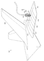
【解決手段】細長部材601と、フランジ603と、測定システムと、を備えることができる。細長部材の端部は602、第1構造604の穴630を通って移動して、第1構造604と第2構造605との間に位置する空間606に進入するように構成される。フランジ603は細長部材601から延出する。細長部材603は、フランジが第1構造604の穴630から出た後に突出することにより、フランジ603が穴630を通り抜けて戻ることができないように構成される。測定システムは、細長部材601の端部602の移動量を測定して、第1構造604と第2構造605との間の空間の長さを同定するように構成される。
【選択図】図6
Description
Claims (15)
- 細長部材であって、細長部材の端部が、第1構造の穴を通って移動して、第1構造と第2構造との間に位置する空間に進入するように構成される、細長部材と、
細長部材から延出するフランジであって、フランジが穴を通り抜けて戻ることができないように、フランジが第1構造の穴から出た後に、細長部材が突出するように構成される、フランジと、
細長部材の端部の移動量を測定して、第1構造と第2構造との間の空間の長さを同定するように構成される、測定システムと
を備える、装置。 - 細長部材は、細長部材の第1端部から延出する通路を有し、そして装置は更に、通路の内部を移動するように構成されるロッドを備え、フランジが第1構造の穴から出た後にロッドが第1位置から第2位置に移動するときに、細長部材が突出するように構成される、請求項1に記載の装置。
- 細長部材は略円筒形状を有し、そして装置は更に、細長部材の端部から或る距離だけ延びる多数のスロットを備える、請求項2に記載の装置。
- 測定システムは、第1構造の外側表面から第2構造の内側表面までの第1距離、及び第1構造の外側表面から第1構造の内側表面までの第2距離を測定するように構成され、空間の距離は、第1距離と第2距離との差である、請求項1乃至3の何れか1項に記載の装置。
- 空間を測定する装置であって、
第1端部を有するチューブであって、チューブの第1端部が、後退位置と突出位置との間を移動するように構成され、チューブが、第1端部に近接する少なくとも1つの切り欠き部を有する、チューブと、
第1端部に近接配置されるフランジであって、フランジが、上側表面及び下側表面を有し、フランジが或る厚さによって特徴付けられ、フランジ及び第1端部が、第1端部が後退位置にあるときに第1部品の穴を通過するように構成され、フランジが、第1端部が突出位置にあるときにフランジの上側表面が第1部品の下側表面に接触するように構成される、フランジと、
チューブ内に移動可能に配置されるロッドであって、ロッドがチューブに第1端部に近接して挿入されるときにチューブを突出位置に移動させるように構成される、ロッドと、
チューブの移動量を記録するように構成される測定デバイスと
を備える、装置。 - チューブの第1端部は、静止時に後退位置にある、請求項5に記載の装置。
- チューブの第1端部は、ロッドがチューブから取り出されるときに後退位置に移動するように構成される、請求項6に記載の装置。
- チューブの第1端部は、静止時に突出位置にある、請求項5に記載の装置。
- 圧迫部材をチューブの第1端部に近接して移動させ、かつ切り欠き部の上を移動させるとチューブの第1端部が後退位置に移動するように、チューブの外側表面に沿って直線状に移動するように構成される圧迫部材を更に備える、請求項8に記載の装置。
- 第1部品と第2部品との間の空間を測定する方法であって、
チューブの上に配置されるフランジの下側表面が第2部品の第1表面に接触するまで、チューブの第1端部を第1部品の穴に挿通させるステップと、
第1部品の第1表面と第2部品の第1表面との間の距離の測定を第1測定として行うステップと、
チューブの上に配置されるフランジの上側表面が、第1部品の第2表面に接触するまで、チューブを上昇させるステップと、
第1部品の第1表面と第1部品の第2表面との間の距離の測定を第2測定として行うステップと、
第1部品の第2表面と第2部品の第1表面との間の空間を測定するステップと
を含む、方法。 - 更に、チューブの第1端部の周りに配置される突出部が、第1部品の第1表面に接触して配置されるときに、測定デバイスをゼロ設定するステップを含む、請求項10に記載の方法。
- 更に、チューブの第1端部が第1部品と第2部品との間の空間内に位置決めされるときに、チューブの第1端部を突出位置に突出させるステップを含む、請求項10又は11に記載の方法。
- チューブの第1端部を突出させるステップでは更に、ロッドをチューブ内に挿入して、チューブの第1端部を突出させる、請求項12に記載の方法。
- 空間を測定するステップでは、第2測定による値を第1測定による値から減算し、そしてフランジの厚さを考慮に入れる、請求項10乃至13の何れか1項に記載の方法。
- 第1部品の第1表面と第2部品の第1表面との間の距離の測定を第1測定として行うステップ、及び第1部品の第1表面と第1部品の第2表面との間の距離の測定を第2測定として行うステップは、逆の順番で行われる、請求項10乃至14の何れか1項に記載の方法。
Applications Claiming Priority (2)
| Application Number | Priority Date | Filing Date | Title |
|---|---|---|---|
| US13/169,945 US8336222B1 (en) | 2011-06-27 | 2011-06-27 | Method and apparatus for measuring spaces with limited access |
| US13/169,945 | 2011-06-27 |
Publications (3)
| Publication Number | Publication Date |
|---|---|
| JP2013011602A true JP2013011602A (ja) | 2013-01-17 |
| JP2013011602A5 JP2013011602A5 (ja) | 2015-07-16 |
| JP6397605B2 JP6397605B2 (ja) | 2018-09-26 |
Family
ID=46639281
Family Applications (1)
| Application Number | Title | Priority Date | Filing Date |
|---|---|---|---|
| JP2012136830A Expired - Fee Related JP6397605B2 (ja) | 2011-06-27 | 2012-06-18 | 接近が制限される空間を測定する方法及び装置 |
Country Status (4)
| Country | Link |
|---|---|
| US (1) | US8336222B1 (ja) |
| EP (1) | EP2541190B1 (ja) |
| JP (1) | JP6397605B2 (ja) |
| CA (1) | CA2775866C (ja) |
Cited By (2)
| Publication number | Priority date | Publication date | Assignee | Title |
|---|---|---|---|---|
| JP2017087186A (ja) * | 2015-11-16 | 2017-05-25 | 株式会社Screenホールディングス | 塗布装置、製造装置および測定方法 |
| KR101949085B1 (ko) | 2018-06-21 | 2019-02-15 | 신윤은 | 시트 캐리어의 전방 내경 길이 측정방법 |
Families Citing this family (12)
| Publication number | Priority date | Publication date | Assignee | Title |
|---|---|---|---|---|
| CN104482840B (zh) * | 2014-11-20 | 2017-09-19 | 航天海鹰(镇江)特种材料有限公司 | 用于检测复合材料壁板贴模间隙的施力装置及检测方法 |
| US10168136B2 (en) | 2016-03-22 | 2019-01-01 | Rolls-Royce Corporation | Clearance gage |
| US10286556B2 (en) * | 2016-10-16 | 2019-05-14 | The Boeing Company | Method and apparatus for compliant robotic end-effector |
| US10330453B2 (en) | 2017-03-29 | 2019-06-25 | Lockheed Martin Corporation | Wireless fastener grip gauge |
| CN109798828B (zh) * | 2017-11-17 | 2022-11-22 | 上海仪器仪表研究所 | 一种法兰定位仪 |
| CN109059728B (zh) * | 2018-08-02 | 2023-09-22 | 江苏理工学院 | 一种圆周孔位置尺寸误差检测工具 |
| CN109579675B (zh) * | 2019-01-09 | 2023-09-08 | 山东太古飞机工程有限公司 | 一种用于测量飞机蒙皮凹凸程度的测量辅助工装 |
| CN113074613A (zh) * | 2020-03-16 | 2021-07-06 | 江山市发发科技有限公司 | 杆体端面盲孔深度检测装置 |
| CN111238346B (zh) * | 2020-03-16 | 2022-02-25 | 江山跟政科技有限公司 | 工件表面凹坑检验方法 |
| CN111238345B (zh) * | 2020-03-16 | 2021-08-17 | 长沙五量汽车配件有限公司 | 杆体端面盲孔深度检测方法 |
| CN111238347B (zh) * | 2020-03-16 | 2021-07-27 | 常州市鑫亿莱精密机械有限公司 | 工件表面凹坑检验装置 |
| US11920915B2 (en) * | 2021-04-07 | 2024-03-05 | The Boeing Company | Non-contact measurement for interface gaps |
Citations (7)
| Publication number | Priority date | Publication date | Assignee | Title |
|---|---|---|---|---|
| US2490364A (en) * | 1948-02-27 | 1949-12-06 | Herman H Livingston | Bone pin |
| JPS5036117B1 (ja) * | 1970-07-08 | 1975-11-21 | ||
| JPS59103203U (ja) * | 1982-12-27 | 1984-07-11 | 株式会社東芝 | 測定装置 |
| JPS6015607U (ja) * | 1983-07-11 | 1985-02-02 | トヨタ自動車株式会社 | 隙間測定装置 |
| JPS60137302U (ja) * | 1984-02-24 | 1985-09-11 | 多摩川精機株式会社 | 穴内寸法測定装置 |
| JP2007111538A (ja) * | 2001-06-14 | 2007-05-10 | Intrinsic Therapeutics Inc | 椎間の診断用および処置用機器 |
| JP2010046307A (ja) * | 2008-08-22 | 2010-03-04 | Japan Medical Materials Corp | 骨固定器具 |
Family Cites Families (15)
| Publication number | Priority date | Publication date | Assignee | Title |
|---|---|---|---|---|
| US2650435A (en) * | 1950-07-10 | 1953-09-01 | Lloyd L Kidd | Multipurpose depth gauge |
| US2888751A (en) * | 1956-03-05 | 1959-06-02 | Hamilton Watch Co | Gauge attachment |
| US2910781A (en) * | 1957-03-29 | 1959-11-03 | Starrett L S Co | Dial hole gauge |
| US4033043A (en) * | 1975-07-09 | 1977-07-05 | Cunningham Frank W | Gauge for measuring length of an opening |
| US4837615A (en) | 1987-09-29 | 1989-06-06 | Textron Inc. | Gap measuring apparatus |
| US4848137A (en) | 1988-03-23 | 1989-07-18 | The Boeing Company | Automated shim manufacturing system |
| US4930226A (en) * | 1989-05-22 | 1990-06-05 | Deere & Company | Sensor adjustment gauge |
| US5013318A (en) * | 1990-07-31 | 1991-05-07 | Special Devices Incorporated | Medical instrument for measuring depth of fastener hold in bone |
| US5497560A (en) * | 1995-01-27 | 1996-03-12 | Pasquerella; David | Depth finder |
| US7717961B2 (en) | 1999-08-18 | 2010-05-18 | Intrinsic Therapeutics, Inc. | Apparatus delivery in an intervertebral disc |
| US7216441B2 (en) * | 2005-07-29 | 2007-05-15 | Robert Alan Batora | Apparatus for measuring step height or depth against another surface |
| US7730789B2 (en) | 2006-11-01 | 2010-06-08 | Boeing Management Company | Device and method for measuring a gap between members of a structure for manufacture of a shim |
| US7607238B2 (en) * | 2006-11-07 | 2009-10-27 | Eidosmed Llc | Digital depth gauge |
| US20090005786A1 (en) | 2007-06-28 | 2009-01-01 | Stryker Trauma Gmbh | Bone hole measuring device |
| US7913411B2 (en) * | 2008-03-21 | 2011-03-29 | Dorsey Metrology International | Digital bore gage handle |
-
2011
- 2011-06-27 US US13/169,945 patent/US8336222B1/en not_active Expired - Fee Related
-
2012
- 2012-04-30 CA CA2775866A patent/CA2775866C/en active Active
- 2012-06-12 EP EP12171644.3A patent/EP2541190B1/en active Active
- 2012-06-18 JP JP2012136830A patent/JP6397605B2/ja not_active Expired - Fee Related
Patent Citations (7)
| Publication number | Priority date | Publication date | Assignee | Title |
|---|---|---|---|---|
| US2490364A (en) * | 1948-02-27 | 1949-12-06 | Herman H Livingston | Bone pin |
| JPS5036117B1 (ja) * | 1970-07-08 | 1975-11-21 | ||
| JPS59103203U (ja) * | 1982-12-27 | 1984-07-11 | 株式会社東芝 | 測定装置 |
| JPS6015607U (ja) * | 1983-07-11 | 1985-02-02 | トヨタ自動車株式会社 | 隙間測定装置 |
| JPS60137302U (ja) * | 1984-02-24 | 1985-09-11 | 多摩川精機株式会社 | 穴内寸法測定装置 |
| JP2007111538A (ja) * | 2001-06-14 | 2007-05-10 | Intrinsic Therapeutics Inc | 椎間の診断用および処置用機器 |
| JP2010046307A (ja) * | 2008-08-22 | 2010-03-04 | Japan Medical Materials Corp | 骨固定器具 |
Cited By (3)
| Publication number | Priority date | Publication date | Assignee | Title |
|---|---|---|---|---|
| JP2017087186A (ja) * | 2015-11-16 | 2017-05-25 | 株式会社Screenホールディングス | 塗布装置、製造装置および測定方法 |
| WO2017086078A1 (ja) * | 2015-11-16 | 2017-05-26 | 株式会社Screenホールディングス | 塗布装置、製造装置および測定方法 |
| KR101949085B1 (ko) | 2018-06-21 | 2019-02-15 | 신윤은 | 시트 캐리어의 전방 내경 길이 측정방법 |
Also Published As
| Publication number | Publication date |
|---|---|
| US8336222B1 (en) | 2012-12-25 |
| CA2775866A1 (en) | 2012-12-27 |
| EP2541190B1 (en) | 2023-10-04 |
| JP6397605B2 (ja) | 2018-09-26 |
| EP2541190A1 (en) | 2013-01-02 |
| CA2775866C (en) | 2015-07-14 |
| US20120324749A1 (en) | 2012-12-27 |
Similar Documents
| Publication | Publication Date | Title |
|---|---|---|
| JP6397605B2 (ja) | 接近が制限される空間を測定する方法及び装置 | |
| US9879981B1 (en) | Systems and methods for evaluating component strain | |
| JP7668857B2 (ja) | 径測定を複数同時に行うためのプラグゲージと、これに関連するシステム及び方法 | |
| US20150000387A1 (en) | Method for checking cooling holes of a gas turbine blade | |
| CN101813471A (zh) | 接触式测量装置 | |
| CN107063079B (zh) | 测量在两个环向元件之间的受限空间中的相对同心度偏差 | |
| US11725922B2 (en) | Jig for and method of measuring length of stud bolt | |
| US10569382B2 (en) | Abrasive tool indicator system, method and apparatus | |
| CN109625317B (zh) | 一种兼有飞机与发动机部件涡流检查功能的检测仪器 | |
| CN216049506U (zh) | 一种用于孔距测量的游标卡尺 | |
| CN116105648A (zh) | 一种多孔空间位置度检测装置及制作和检测方法 | |
| JP5113665B2 (ja) | 渦電流探傷センサー用治具並びに渦電流探傷センサー | |
| CN212432458U (zh) | 弹性测量装置 | |
| US20090199652A1 (en) | Tensile specimen measuring apparatus and method | |
| CN223869983U (zh) | 一种内腔测量组件 | |
| CN114739556B (zh) | 二次剖切轮廓法残余应力测试方法 | |
| CN110857845A (zh) | 一种检测热成型模具底板与压机的匹配性的方法 | |
| CN118149673A (zh) | 一种用于检测内孔到端面距离的测具及测量方法 | |
| CN103817492A (zh) | 龙门式可调节测量机加工方法 | |
| CN112985317A (zh) | 检测装置及方法 | |
| ITMI20130260U1 (it) | Unita' di controllo multiplo e metodo di controllo, particolarmente per attrezzature utilizzate nella produzione di vetro cavo. | |
| BR102020004195B1 (pt) | Método e sistema para produzir um calço | |
| Davies et al. | Zirconium Plate Measuring Instrument (ZPMI) Design Report |
Legal Events
| Date | Code | Title | Description |
|---|---|---|---|
| A521 | Request for written amendment filed |
Free format text: JAPANESE INTERMEDIATE CODE: A523 Effective date: 20150528 |
|
| A621 | Written request for application examination |
Free format text: JAPANESE INTERMEDIATE CODE: A621 Effective date: 20150528 |
|
| A977 | Report on retrieval |
Free format text: JAPANESE INTERMEDIATE CODE: A971007 Effective date: 20160526 |
|
| A131 | Notification of reasons for refusal |
Free format text: JAPANESE INTERMEDIATE CODE: A131 Effective date: 20160607 |
|
| A521 | Request for written amendment filed |
Free format text: JAPANESE INTERMEDIATE CODE: A523 Effective date: 20160809 |
|
| A02 | Decision of refusal |
Free format text: JAPANESE INTERMEDIATE CODE: A02 Effective date: 20170117 |
|
| A521 | Request for written amendment filed |
Free format text: JAPANESE INTERMEDIATE CODE: A523 Effective date: 20170406 |
|
| A911 | Transfer to examiner for re-examination before appeal (zenchi) |
Free format text: JAPANESE INTERMEDIATE CODE: A911 Effective date: 20170413 |
|
| A912 | Re-examination (zenchi) completed and case transferred to appeal board |
Free format text: JAPANESE INTERMEDIATE CODE: A912 Effective date: 20170623 |
|
| A521 | Request for written amendment filed |
Free format text: JAPANESE INTERMEDIATE CODE: A523 Effective date: 20180423 |
|
| A61 | First payment of annual fees (during grant procedure) |
Free format text: JAPANESE INTERMEDIATE CODE: A61 Effective date: 20180903 |
|
| R150 | Certificate of patent or registration of utility model |
Ref document number: 6397605 Country of ref document: JP Free format text: JAPANESE INTERMEDIATE CODE: R150 |
|
| R250 | Receipt of annual fees |
Free format text: JAPANESE INTERMEDIATE CODE: R250 |
|
| R250 | Receipt of annual fees |
Free format text: JAPANESE INTERMEDIATE CODE: R250 |
|
| R250 | Receipt of annual fees |
Free format text: JAPANESE INTERMEDIATE CODE: R250 |
|
| LAPS | Cancellation because of no payment of annual fees |