JP2013017635A - Chair - Google Patents
Chair Download PDFInfo
- Publication number
- JP2013017635A JP2013017635A JP2011153057A JP2011153057A JP2013017635A JP 2013017635 A JP2013017635 A JP 2013017635A JP 2011153057 A JP2011153057 A JP 2011153057A JP 2011153057 A JP2011153057 A JP 2011153057A JP 2013017635 A JP2013017635 A JP 2013017635A
- Authority
- JP
- Japan
- Prior art keywords
- hole
- side plate
- rod
- armrest
- bolt
- Prior art date
- Legal status (The legal status is an assumption and is not a legal conclusion. Google has not performed a legal analysis and makes no representation as to the accuracy of the status listed.)
- Granted
Links
Images




Landscapes
- Bathtubs, Showers, And Their Attachments (AREA)
Abstract
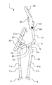
【課題】上下回動自在な肘掛けを備えた椅子において、軽量且つ簡素な構造により、肘掛けを上下回動自在に支持するボルトとナットとの緩みを防止する。
【解決手段】椅子は、棒状部12に上下回動自在に支持された肘掛けを備える。肘掛けは、肘掛けの孔51aおよび52a、カバー部材の孔55a、取付台18の孔18a、および棒状部12の孔12aを貫通するボルト66と、ボルト66の先端部に締め付けられたナット67とにより、棒状部12に上下回動自在に取り付けられている。上記孔51a、52a、18a、12aの内周面とボルト66との間に、カラー部材65が介在している。
【選択図】図6In a chair having an armrest that can be pivoted up and down, a lightweight and simple structure prevents a bolt and a nut that support the armrest from pivoting up and down.
A chair includes an armrest that is supported by a rod-like portion 12 so as to be rotatable up and down. The armrest is formed by an armrest hole 51a and 52a, a cover member hole 55a, a hole 18a of the mounting base 18, and a bolt 66 penetrating the hole 12a of the rod-shaped portion 12, and a nut 67 fastened to the tip of the bolt 66. The rod-like portion 12 is attached so as to be rotatable up and down. A collar member 65 is interposed between the inner peripheral surfaces of the holes 51a, 52a, 18a, and 12a and the bolt 66.
[Selection] Figure 6
Description
本発明は、上下に回動自在な肘掛けを有し、浴室等にて好適に利用可能な椅子に関する。 The present invention relates to a chair that has an armrest that can be pivoted up and down and can be suitably used in a bathroom or the like.
高齢者等が浴室等で使用する椅子として、上下に回動自在な肘掛けを備えた椅子がよく用いられている。このような椅子によれば、肘掛けを上方へ回動させることによって(言い換えると、肘掛けを跳ね上げることによって)、座部の側方を開放することができる。そのため、高齢者等にとって、座部に座る動作等が容易となる。また、浴室等の狭いスペースで利用される椅子では、非使用時には折り畳むことによってコンパクトにできることが好ましい。上下回動自在な肘掛けを備えた椅子によれば、折り畳んだ際に肘掛けを回動させることにより、肘掛けが出っ張らないようにすることができ、コンパクトにすることができる。 As a chair used by elderly people in a bathroom or the like, a chair having an armrest that can be pivoted up and down is often used. According to such a chair, the side of the seat can be opened by rotating the armrest upward (in other words, by flipping up the armrest). Therefore, for the elderly and the like, the operation of sitting on the seat becomes easy. In addition, it is preferable that a chair used in a narrow space such as a bathroom can be made compact by folding when not in use. According to a chair provided with an armrest that can be pivoted up and down, the armrest can be prevented from sticking out by rotating the armrest when folded, and can be made compact.
特許文献1には、そのような肘掛けを備えた椅子が開示されている。特許文献1に開示された椅子の肘掛けは、ヒンジピンを介して前脚および後脚に回動自在に支持されている。詳しくは、前脚は貫通孔が形成された固定板を備え、後脚は貫通孔が形成された後脚本体を備え、肘掛けは貫通孔が形成された肘掛け本体を備えている。肘掛け本体、固定板、および後脚本体は、それら貫通孔が左右に並ぶように並置される。それらの貫通孔には、ボルトからなるヒンジピンが挿通され、ヒンジピンの先端にはナットが締め付けられる。これにより、肘掛けはヒンジピンを介して前脚および後脚に回動自在に支持される。
ところで上記椅子では、例えば、左右方向に荷重が加わった状態で肘掛けを跳ね上げた場合に、ヒンジピンの外周面が肘掛けの貫通孔の内周面に強く接触すると共に、ナットの側面が後脚本体の側面と強く接触することがある。この場合、ヒンジピンと肘掛けとの摩擦により、ヒンジピンは肘掛けと共に回転しようとする力を受ける一方、ナットと後脚本体との摩擦により、ナットは後脚本体と共に静止し続けようとする力を受ける。そのため、ヒンジピンとナットとには、互いに相対回転しようとする力が加わってしまい、その結果、ヒンジピンとナットとが緩んでしまうという課題があった。 By the way, in the above chair, for example, when the armrest is flipped up with a load applied in the left-right direction, the outer peripheral surface of the hinge pin strongly contacts the inner peripheral surface of the through-hole of the armrest, and the side surface of the nut is the rear leg main body. May come into strong contact with the sides of In this case, the hinge pin receives a force to rotate with the armrest due to friction between the hinge pin and the armrest, while the nut receives a force to keep stationary with the rear leg body due to friction between the nut and the rear leg body. For this reason, the hinge pin and the nut are subjected to a force to rotate relative to each other, resulting in a problem that the hinge pin and the nut are loosened.
ここで、ヒンジピンとナットとが緩んでしまわないように、緩み止め用の特殊な構造を付加することが考えられる。しかし、軽量且つ簡素な構造が望まれる椅子、例えば浴室用椅子等では、重たい構造物や複雑な構造物を付加することは好ましくない。 Here, it is conceivable to add a special structure for preventing loosening so that the hinge pin and the nut are not loosened. However, it is not preferable to add a heavy structure or a complicated structure to a chair that requires a light and simple structure, such as a bathroom chair.
本発明はかかる点に鑑みてなされたものであり、その目的とするところは、上下回動自在な肘掛けを備えた椅子において、軽量且つ簡素な構造により、肘掛けを上下回動自在に支持する構造の緩みを防止することにある。 The present invention has been made in view of such a point, and an object of the present invention is a structure that supports an armrest so that the armrest can be pivoted up and down by a lightweight and simple structure in a chair equipped with an armrest that can pivot up and down. It is to prevent the loosening of.
本発明に係る椅子は、使用者が着座する座部と、前記座部を支持する脚部と、正面視において前記座部の側部よりも上方にて上向きに延びる棒状部と、前記棒状部に上下回動自在に支持された肘掛けと、を備えた椅子である。前記棒状部には、左右方向に貫通する孔が形成されている。前記肘掛けは、それぞれ左右方向に貫通する孔が形成された左側板部および右側板部を有し、前記左側板部と前記右側板部との間に前記棒状部が位置するように配置される。前記椅子は更に、前記左側板部および前記右側板部の一方から他方に向かって挿入され、前記左側板部の孔と前記棒状部の孔と前記右側板部の孔とを貫通するボルトと、前記ボルトの先端部に締め付けられ、前記左側板部および前記右側板部の他方と接触するナットと、少なくとも前記棒状部の孔に挿入され、その内部に前記ボルトが挿通されることにより、前記棒状部の孔の内周面と前記ボルトとの間に介在するカラー部材と、を備えている。 The chair according to the present invention includes a seat portion on which a user is seated, a leg portion that supports the seat portion, a rod-like portion that extends upward above a side portion of the seat portion in a front view, and the rod-like portion. And an armrest supported so as to be pivotable up and down. The rod-like portion is formed with a hole penetrating in the left-right direction. The armrest has a left side plate portion and a right side plate portion in which holes penetrating in the left-right direction are formed, and is arranged so that the rod-like portion is positioned between the left side plate portion and the right side plate portion. . The chair is further inserted from one of the left side plate portion and the right side plate portion toward the other, and a bolt that penetrates the hole of the left side plate portion, the hole of the rod-like portion, and the hole of the right side plate portion, The rod is tightened to the tip of the bolt and inserted into the hole of at least the rod-shaped portion and the nut contacting the other of the left-side plate portion and the right-side plate portion, and the bolt is inserted into the rod-shaped portion. A collar member interposed between the inner peripheral surface of the hole of the portion and the bolt.
上記椅子によれば、ナットは肘掛け(詳しくは、左側板部または右側板部)と接触している。仮に、棒状部の孔の内周面とボルトとが直接接触しているとすると、左右方向に荷重が加わった状態で肘掛けを跳ね上げた場合に、ナットは肘掛けから回転しようとする力を受ける一方、ボルトは棒状部から、静止し続けようとする力を受けることになる。そのため、ボルトおよびナットが相対回転しようとする力を受けてしまい、ボルトとナットとが緩んでしまうおそれがある。しかし、上記椅子によれば、棒状部の孔の内周面とボルトとの間には、カラー部材が介在している。そのため、ボルトと棒状部の孔の内周面とは、直接接触しないようになっている。したがって、左右方向に荷重が加わった状態で肘掛けを跳ね上げた場合であっても、ボルトは棒状部から静止し続けようとする力を受けることはない。よって、ボルトおよびナットは相対回転するような力を受けないため、ボルトとナットとの緩みを抑制することができる。したがって、上記椅子によれば、棒状部の孔の内周面とボルトとの間にカラー部材を介在させるという軽量且つ簡素な構造により、肘掛けを回動自在に支持する構造の緩みを防止することができる。 According to the chair, the nut is in contact with the armrest (specifically, the left side plate or the right side plate). If the inner surface of the hole in the rod-shaped part and the bolt are in direct contact with each other, the nut will receive a force to rotate from the armrest when the armrest is flipped up with a load applied in the left-right direction. On the other hand, the bolt receives a force from the rod-like portion to keep still. For this reason, the bolt and the nut receive a force of relative rotation, and the bolt and the nut may be loosened. However, according to the chair, the collar member is interposed between the inner peripheral surface of the hole of the rod-like portion and the bolt. For this reason, the bolt and the inner peripheral surface of the hole of the rod-shaped portion are not in direct contact with each other. Therefore, even when the armrest is flipped up in a state where a load is applied in the left-right direction, the bolt does not receive a force that tries to remain stationary from the rod-shaped portion. Therefore, since the bolt and the nut do not receive a force that causes relative rotation, loosening between the bolt and the nut can be suppressed. Therefore, according to the chair described above, the lightweight and simple structure in which the collar member is interposed between the inner peripheral surface of the hole of the rod-like portion and the bolt prevents loosening of the structure that rotatably supports the armrest. Can do.
前記カラー部材は、前記左側板部の孔と前記棒状部の孔と前記右側板部の孔とに挿入され、前記左側板部の孔、前記棒状部の孔、および前記右側板部の孔の内周面と前記ボルトとの間に介在していることが好ましい。 The collar member is inserted into the hole of the left side plate part, the hole of the bar-like part, and the hole of the right side plate part, and the hole of the left side plate part, the hole of the bar-like part, and the hole of the right side plate part It is preferable to interpose between the inner peripheral surface and the bolt.
このことにより、カラー部材の位置が左方または右方にずれたとしても、棒状部の孔の内周面とボルトとが接触してしまうことを抑制することができる。したがって、ボルトとナットとの緩みを、より一層抑制することができる。 Thereby, even if the position of the collar member is shifted to the left or right, it is possible to suppress the contact between the inner peripheral surface of the hole of the rod-shaped portion and the bolt. Therefore, loosening between the bolt and the nut can be further suppressed.
前記カラー部材の長さは、前記ボルトと前記ナットとを締め付ける前の前記左側板部の孔の左端と前記右側板部の孔の右端との間の距離よりも短いことが好ましい。 The length of the collar member is preferably shorter than the distance between the left end of the hole in the left side plate portion and the right end of the hole in the right side plate portion before the bolt and the nut are tightened.
このことにより、ボルトとナットとを締め付ける際に、カラー部材が邪魔になることはない。したがって、ボルトとナットとを円滑に締め付けることができる。 Thus, the collar member does not get in the way when tightening the bolt and nut. Therefore, the bolt and the nut can be smoothly tightened.
前記カラー部材の長さは、前記ボルトと前記ナットとを締め付ける前の前記左側板部の孔の左端と前記右側板部の孔の右端との間の距離よりも、0.1mm〜2mm短いことが好ましい。 The length of the collar member is 0.1 mm to 2 mm shorter than the distance between the left end of the hole in the left side plate part and the right end of the hole in the right side plate part before fastening the bolt and the nut. Is preferred.
このことにより、ボルトとナットとを締め付ける際に、カラー部材が邪魔になることはない。また、ボルトとナットとを締め付けた後に、カラー部材の位置ずれを好適に抑制することができ、棒状部の孔の内周面とボルトとが接触してしまうことを十分に抑制することができる。したがって、ボルトとナットとを円滑に締め付けることができると共に、締め付け後におけるボルトとナットとの緩みを十分に抑制することができる。また、ボルトとナットとを締め付ける際に、過剰に締め付けてしまうことを抑制することができる。したがって、肘掛けが回動しづらいといった作動不良が発生することを防止することができる。 Thus, the collar member does not get in the way when tightening the bolt and nut. Further, after the bolt and nut are tightened, the displacement of the collar member can be suitably suppressed, and the inner peripheral surface of the hole of the rod-shaped portion and the bolt can be sufficiently suppressed. . Therefore, the bolt and the nut can be smoothly tightened, and the loosening between the bolt and the nut after the tightening can be sufficiently suppressed. Moreover, when tightening a bolt and a nut, excessive tightening can be suppressed. Therefore, it is possible to prevent the occurrence of a malfunction such that the armrest is difficult to rotate.
前記左側板部、前記右側板部、および前記棒状部は、金属材料から形成され、前記左側板部と前記棒状部との間、および前記右側板部と前記棒状部との間に、左右方向に貫通する孔が形成された樹脂製のカバー部材が設けられ、前記カラー部材は更に、前記カバー部材の孔に挿入されていることが好ましい。 The left side plate portion, the right side plate portion, and the rod-shaped portion are formed of a metal material, and are arranged in the left-right direction between the left side plate portion and the rod-shaped portion and between the right side plate portion and the rod-shaped portion. It is preferable that a resin cover member in which a hole penetrating is formed is provided, and the collar member is further inserted into the hole of the cover member.
このことにより、金属材料からなる両側板部と棒状部との間に、樹脂製のカバー部材が介在するので、肘掛けの回動に伴って両側板部と棒状部とが直接擦れることを避けることができる。そのため、両側板部および棒状部が削れてしまうことを防止することができる。したがって、両側板部および棒状部の磨耗に起因するボルトおよびナットのがたつきを抑制することができる。 As a result, since the resin cover member is interposed between the both side plate portions and the rod-shaped portion made of the metal material, it is possible to avoid rubbing the both side plate portions and the rod-shaped portion directly with the rotation of the armrest. Can do. Therefore, it can prevent that a both-sides board part and a rod-shaped part are shaved. Therefore, it is possible to suppress the rattling of the bolt and the nut due to the wear of the both side plate portions and the rod-shaped portion.
本発明に係る他の椅子は、使用者が着座する座部と、前記座部を支持する脚部と、正面視において前記座部の側部よりも上方にて上向きに延びる棒状部と、前記棒状部に上下回動自在に支持された肘掛けと、を備えた椅子である。前記肘掛けおよび前記棒状部には、それぞれ左右方向に貫通する孔が形成されている。前記肘掛けは、前記肘掛けの孔と前記棒状部の孔とが揃うように前記棒状部に対して配置される。前記椅子は更に、前記肘掛けの孔および前記棒状部の孔を貫通するボルトと、前記ボルトの先端部に締め付けられ、前記肘掛けおよび前記棒状部の一方と接触するナットと、少なくとも前記肘掛けおよび前記棒状部の他方の孔に挿入され、当該他方の孔の内周面と前記ボルトとの間に介在するカラー部材と、を備えている。 Another chair according to the present invention includes a seat portion on which a user is seated, a leg portion that supports the seat portion, a rod-shaped portion that extends upward above a side portion of the seat portion in a front view, An armrest supported by a rod-like portion so as to be rotatable up and down. The armrest and the rod-shaped portion are respectively formed with holes penetrating in the left-right direction. The armrest is disposed with respect to the rod-shaped portion so that the hole of the armrest and the hole of the rod-shaped portion are aligned. The chair further includes a bolt that passes through the hole in the armrest and the hole in the rod-like portion, a nut that is fastened to a tip portion of the bolt and contacts one of the armrest and the rod-like portion, and at least the armrest and the rod-like shape. A collar member inserted into the other hole of the portion and interposed between the inner peripheral surface of the other hole and the bolt.
上記椅子によれば、ナットは肘掛けおよび棒状部の一方と接触している。仮に、それらのうちの他方の孔の内周面とボルトとが直接接触しているとすると、左右方向に荷重が加わった状態で肘掛けを跳ね上げた場合に、ボルトおよびナットの一方は肘掛けから回転しようとする力を受けるが、他方は棒状部から静止し続けようとする力を受けることになる。そのため、ボルトおよびナットが相対回転しようとする力を受けてしまい、ボルトとナットとが緩んでしまうおそれがある。しかし、上記椅子によれば、カラー部材により、肘掛けおよび棒状部のうちナットと接触している方と異なる方の孔の内周面は、ボルトと直接接触しないようになっている。したがって、左右方向に荷重が加わった状態で肘掛けを跳ね上げた場合であっても、ボルトおよびナットは相対回転するような力を受けないため、ボルトとナットとの緩みを抑制することができる。したがって、上記椅子によれば、軽量且つ簡素な構造により、肘掛けを回動自在に支持する構造の緩みを防止することができる。 According to the chair, the nut is in contact with one of the armrest and the rod-shaped portion. Assuming that the inner peripheral surface of the other hole and the bolt are in direct contact with each other, when the armrest is flipped up with a load applied in the left-right direction, one of the bolt and nut is removed from the armrest. While receiving the force to rotate, the other receives the force to keep stationary from the rod-like portion. For this reason, the bolt and the nut receive a force of relative rotation, and the bolt and the nut may be loosened. However, according to the chair, the inner peripheral surface of the hole different from the one in contact with the nut among the armrest and the rod-like portion is not directly in contact with the bolt by the collar member. Therefore, even when the armrest is flipped up in a state where a load is applied in the left-right direction, the bolt and the nut do not receive a force that causes relative rotation, so that loosening between the bolt and the nut can be suppressed. Therefore, according to the above-mentioned chair, it is possible to prevent loosening of the structure that supports the armrest rotatably with a light and simple structure.
前記椅子は、浴室内で使用される浴室用椅子であってもよい。 The chair may be a bathroom chair used in a bathroom.
浴室用椅子は、狭い浴室内で使用され、また、高齢者等が使用する場合が多いため、小型且つ軽量であることが求められる。上記椅子によれば、肘掛けを回動自在に支持する構造の緩みを軽量且つ簡素な構造によって防止することができるので、浴室用椅子として特に有用である。 The bathroom chair is used in a narrow bathroom and is often used by elderly people and the like, and thus is required to be small and lightweight. According to the above-mentioned chair, loosening of the structure that rotatably supports the armrest can be prevented by a light and simple structure, and thus it is particularly useful as a bathroom chair.
前記脚部は、前方斜め下向きに延びる前脚本体を有する前脚部と、後方斜め下向きに延びる後脚本体を有する後脚部とを有し、前記前脚部と前記後脚部とは、互いに水平軸周りに回動自在に結合され、前記棒状部は、前記前脚部または前記後脚部と一体的に形成されていてもよい。 The leg portion includes a front leg portion having a front leg body extending obliquely forward and downward, and a rear leg portion having a rear leg body extending obliquely rearward and downward, and the front leg portion and the rear leg portion are parallel to each other. The rod-like part may be integrally formed with the front leg part or the rear leg part.
このことにより、上記椅子は、前脚部と後脚部とを互いに回動させることにより、折り畳むことができる。ところで、折り畳み式の椅子は、折り畳むことによってコンパクトに収容することができるという特長を有する。また、折り畳むことによって、容易に運搬することができるという特長を有する。肘掛けを備える折り畳み式の椅子では、上記特長を損なわないように、折り畳んだ際に肘掛けが出っ張らず、また、運搬が容易なように、肘掛けが上下回動自在であることが望まれる。したがって、前述の効果を奏する上記椅子は、折り畳み式の椅子として特に有用である。 Thus, the chair can be folded by rotating the front leg portion and the rear leg portion relative to each other. By the way, the foldable chair has a feature that it can be compactly accommodated by folding. Moreover, it has the feature that it can be easily transported by folding. In a foldable chair provided with an armrest, it is desired that the armrest does not protrude when folded and that the armrest can be pivoted up and down so that it can be easily transported so as not to impair the above-mentioned features. Therefore, the above-mentioned chair that exhibits the above-described effect is particularly useful as a folding chair.
本発明によれば、上下回動自在な肘掛けを備えた椅子において、軽量且つ簡素な構造により、肘掛けを上下回動自在に支持する構造の緩みを防止することができる。 According to the present invention, in a chair provided with an armrest that can be pivoted up and down, loosening of the structure that supports the armrest so as to pivot up and down can be prevented by a light and simple structure.
以下、図面を参照しながら、本発明の実施の形態について説明する。図1は本実施形態に係る椅子1の正面図、図2は椅子1の左側面図である。本実施形態に係る椅子1は、主に高齢者や身体障害者等が浴室内でシャワーを浴びるとき等に利用される椅子であり、いわゆる浴室用椅子である。また、椅子1は、非使用時等には折り畳んでコンパクトにすることができる折り畳み式の椅子である(図4参照)。ただし、本発明に係る椅子は、浴室用椅子1に限定される訳ではなく、浴室以外の場所で使用される椅子であってもよいことは勿論である。また、本発明に係る椅子は、折り畳み式の椅子に限らず、折り畳むことのできない椅子であってもよい。
Hereinafter, embodiments of the present invention will be described with reference to the drawings. FIG. 1 is a front view of a
以下の説明では、前、後、左、右は、椅子1に着座した者から見た前、後、左、右を言うものとする。図1および図2に示すように、椅子1は、第1フレーム10と、左右一対の第2フレーム21と、座部30と、背もたれ40と、左右一対の肘掛け50とを備えている。
In the following description, front, rear, left, and right refer to front, rear, left, and right as viewed from the person seated on the
第1フレーム10は、左右一対の前脚部11と、各前脚部11の後端部から後方斜め上向きに延びる棒状部12と、左右の棒状部12の上端部同士を連結する連結部13とから構成されている。図2に示すように、前脚部11は、前後方向に延びる水平部11aと、水平部11aの前端部から前方斜め下向きに延びる内パイプ部11bと、内パイプ部11bが挿入された外パイプ部11cとを有している。外パイプ部11cの下端部には、滑りを防止するためのゴム脚5が嵌め込まれている。なお、第1フレーム10は、必ずしも水平部11aを備えていなくてもよい。内パイプ部11bと棒状部12とが連続していてもよい。本実施形態では、左右の内パイプ部11b、左右の水平部11a、左右の棒状部12、および連結部13は、一体的に形成されている。しかし、それらの一または二以上のものが別体に形成され、溶接等により接合されていてもよい。第1フレーム10の材料は特に限定される訳ではなく、例えば、アルミニウムやステンレス等の金属、または合成樹脂等を好適に用いることができる。ここでは、第1フレーム10は金属製である。
The
第2フレーム21は、後脚部を構成している。第2フレーム21は、前後方向に延びる水平部21aと、水平部21aの後端部から後方斜め下向きに延びる内パイプ部21bと、内パイプ部21bが挿入された外パイプ部21cとを有している。ただし、第2フレーム21は必ずしも水平部21aを備えている必要はなく、水平部21aは適宜省略することが可能である。第2フレーム21の材料も特に限定される訳ではなく、例えば、アルミニウムやステンレス等の金属、または合成樹脂等を好適に用いることができる。本実施形態では、第2フレーム21は第1フレーム10と同様、金属製である。外パイプ部21cの下端部には、滑りを防止するためのゴム脚5が嵌め込まれている。
The
第1フレーム10の水平部11aと第2フレーム21の水平部21aとは、水平軸61を介して連結されている。第2フレーム21は第1フレーム10に対し、水平軸61周りに回動可能に取り付けられている。図4に示すように、第1フレーム10と第2フレーム21とを水平軸61周りに回動させることにより、椅子1を折り畳むことができる。
The
前脚部11は、外パイプ部11cに対する内パイプ部11bの挿入量を調整することにより、長さの調整が可能となっている。後脚部としての第2フレーム21も、外パイプ部21cに対する内パイプ部21bの挿入量を調整することにより、長さの調整が可能となっている。内パイプ部11bおよび外パイプ部11cと、内パイプ部21bおよび外パイプ部21cとは、ほぼ同一の構成を有している。そこで以下では、内パイプ部21bおよび外パイプ部21cの構成を説明し、内パイプ部11bおよび外パイプ部11cの構成の説明は省略する。
The length of the
図1に示すように、外パイプ部21cには、上下に並ぶ複数の孔26が形成されている。内パイプ部21bには、孔26と同程度の大きさの突起25が形成されている。突起25は図示しないばね等によって内パイプ部21bの側方に向かって付勢されているが、側方から押し付けることにより、内パイプ部21b内に埋没させることができる。外パイプ部21cに対する内パイプ部21bの挿入量を調整し、突起25と所望の孔26との位置を合わせた後、押し付けていた突起25を放すと、突起25は上記孔26に嵌り込む。これにより、内パイプ部21bを外パイプ部21cに固定することができる。このように、突起25と係合させる孔26を適宜選択することにより、後脚部としての第2フレーム21の長さを段階的に調整することができる。説明は省略するが、前脚部11についても同様である。前脚部11および後脚部(すなわち、第2フレーム21)の長さを変更することにより、使用者の体格に合わせて、座部30および肘掛け50の床面からの高さを調整することができる。
As shown in FIG. 1, the
図4に示すように、座部30は、回転軸62を介して、第2フレーム21の水平部21aの先端部分に取り付けられている。座部30は第2フレーム21に対して回動可能である。第1フレーム10の左右の水平部11aには、左右に延びるバー71およびバー73が架け渡されている。左右の第2フレーム21の水平部21aには、左右に延びるバー72が架け渡されている。座部30は、椅子1が折り畳まれた非使用時(図4参照)にはそれらのバー71,72,73から離反するが、使用時(図2参照)にはそれらのバー71,72,73に支持される。座部30は、それらのバー71,72,73を介して、第1フレーム10の水平部11aおよび第2フレーム21の水平部21aに支持される。
As shown in FIG. 4, the
図1に示すように、第1フレーム10の左右の棒状部12の上端部同士は、連結部13を介して接続されている。連結部13は、左右に延びるパイプ状に形成されている。背もたれ40は連結部13の前部に取り付けられている。ただし、連結部13は必ずしも必要ではなく、背もたれ40は適宜省略することができる。
As shown in FIG. 1, the upper ends of the left and right rod-
図1に示すように、棒状部12は、正面視において、座部30の側部よりも上方にて上向きに延びている。本実施形態では、棒状部12は後方斜め上向きに延びており、鉛直方向から傾いているが、棒状部12は鉛直方向に延びていてもよい。また、棒状部12は、前方斜め上向きに延びていてもよい。棒状部12は真っ直ぐに延びていてもよく、曲がっていてもよい。本実施形態では、棒状部12は中空状に形成されている。言い換えると、棒状部12はパイプによって形成されている。ただし、棒状部12は中実状であってもよい。棒状部12の断面形状は円形状に限らず、四角形状、六角形状等の他の形状であってもよい。
As shown in FIG. 1, the rod-
肘掛け50は、棒状部12に上下回動可能に取り付けられている。すなわち、肘掛け50は回動式のものである。使用者が椅子1に座るときには、例えば図3に示すように、肘掛け50を上向きに回動させて跳ね上げることにより、座部30の側方を開放することができる。これにより、使用者は側方から座部30に容易に着座することができる。使用者が座部30に着座した後は、肘掛け50を逆方向に回動させることによって、図2に示すように、肘掛け50を略水平な姿勢にすることができる。これにより、使用者は両手を肘掛け50の上に置き、椅子1の上に安定して座ることができる。
The
前述したように、本実施形態に係る椅子1は折り畳み可能な椅子である。図4に示すように、椅子1を折り畳んだ際、肘掛け50を跳ね上げることにより、肘掛け50が出っ張らないようにすることができる。そのため、椅子1は、コンパクトに収納することができる。また、コンパクトにすることができるので、容易に持ち運ぶことが可能となる。
As described above, the
次に、肘掛け50と、肘掛け50を上下回動自在に支持する各部材とについて説明する。なお、以下では、肘掛け50と肘掛け50を上下回動自在に支持する各部材との全体を、便宜上、肘掛け構造と称することとする。
Next, the
図5に示すように、肘掛け50は、肘掛け本体51と、肘掛け本体51を支持する支持体52とからなっている。肘掛け本体51の根元部は左右に分岐し、互いに左右に離間する左側板51Lと右側板51Rとが形成されている。左側板51Lおよび右側板51Rには、左右方向に貫通する孔51aがそれぞれ形成されている。
As shown in FIG. 5, the
支持体52は、左側板52Lと、右側板52Rと、左側板52Lおよび右側板52Rの先端部をつなぐ天板52Bとから構成されている。これら左側板52Lと右側板52Rと天板52Bとは一体形成されている。ただし、左側板52Lと右側板52Rと天板52Bとは、互いに別体に形成され、組み合わされていてもよい。左側板52Lと右側板52Rとは左右に離間している。左側板52Lおよび右側板52Rには、左右方向に貫通する孔52aがそれぞれ形成されている。左側板52Lと右側板52Rとには、棒状体からなる架設部材53が架け渡されている。架設部材53は、孔52aの前方斜め下の位置にて左右方向に延びている。左側板52Lおよび右側板52Rの架設部材53よりも後方の位置には、段部54が設けられている。
The
支持体52は、肘掛け本体51の内側に嵌め込まれ、肘掛け本体51に固定される。支持体52の天板52Bは、肘掛け本体51の下部に固定される。支持体52の左側板52Lは肘掛け本体51の左側板51Lの右方に配置され、支持体52の右側板52Rは肘掛け本体51の右側板51Rの左方に配置される。これら左側板51Lおよび左側板52Lによって、肘掛け50の左側板部が形成され、右側板51Rおよび右側板52Rによって、肘掛け50の右側板部が形成されている。
The
なお、肘掛け50は、必ずしも肘掛け本体51および支持体52の2つの部材から構成されている必要はない。肘掛け50は、3つ以上の部材を組み合わせることによって構成されていてもよい。また、肘掛け50は、単一の部材によって構成されていてもよい。
The
棒状部12には、樹脂製のカバー部材55が取り付けられている。カバー部材55は、左側板55Lと、右側板55R(図6参照)と、これら左側板55Lおよび右側板55Rを連結する中央板55Cとを有している。カバー部材55は、棒状部12が左側板55Lと右側板55Rとの間に配置されるようにして、棒状部12に取り付けられる。左側板55Lおよび右側板55Rには、左右方向に貫通する孔55aがそれぞれ形成されている。
A
また、左側板55Lおよび右側板55Rには、支持体52の架設部材53がスライド自在に係合するスライド溝56がそれぞれ形成されている。支持体52の架設部材53がスライド溝56内をスライドすることにより、肘掛け50の回動が案内され、また、肘掛け50の所定量以上の回動が規制される。
The
また、カバー部材55には、左側板55Lおよび右側板55Rを貫通するストッパ57が設けられている。ストッパ57は、左側板55Lの左方および右側板55Rの右方に突出している。跳ね上げられた状態から肘掛け50を下方に回動させると、支持体52の段部54がストッパ57と当接し、肘掛け50は、水平な姿勢となる所定の位置に維持される。使用者が肘掛け50に加えた荷重は、支持体52の段部54およびストッパ57を介して棒状部12に支持される。
The
棒状部12とカバー部材55との間には、断面コ字状の取付台18が設けられている。取付台18はカバー部材55および肘掛け50を安定して取り付けるためのものであり、棒状部12に溶接されている。ただし、棒状部12に対する取付台18の固定態様は特に限定される訳ではない。図6に示すように、取付台18は、棒状部12の左側に固定された左側板18Lと、棒状部12の右側に固定された右側板18Rとを有している。図示は省略するが、左側板18Lと右側板18Rとの前端部同士は、中央板によって連結されている。左側板18Lおよび右側板18Rには、左右方向に貫通する孔18aがそれぞれ形成されている。
A mounting
図6に示すように、棒状部12には、左右方向に貫通する孔12aが形成されている。肘掛け本体51の左側板51Lの孔51a、支持体52の左側板52Lの孔52a、カバー部材55の左側板55Lの孔55a、取付台18の左側板18Lの孔18a、棒状部12の孔12a、取付台18の右側板18Rの孔18a、カバー部材55の右側板55Rの孔55a、支持体52の右側板52Rの孔52a、および肘掛け本体51の右側板51Rの孔51aには、カラー部材65が挿入されている。
As shown in FIG. 6, the rod-
カラー部材65は、内周面および外周面が平滑な面からなる円筒部材によって形成されている。ただし、カラー部材65の形状は特に限定される訳ではない。本実施形態では、カラー部材65はステンレスからなっている。ただし、カラー部材65の材料は特に限定されず、アルミニウム等の他の金属であってもよく、樹脂等の他の材料であってもよい。
The
カラー部材65には、左方から右方に向かってボルト66が挿入されている。なお、ボルト66の挿入方向は特に限定されず、ボルト66は右方から左方に向かって挿入されていてもよい。肘掛け本体51の左側板51Lの孔51aの周囲には、右方に凹んだ窪み58Lが形成されている。ボルト66の頭部66aは、窪み58Lの内側に配置されている。ボルト66の頭部66aと肘掛け本体51の左側板51Lとの間には、ワッシャ76が介在している。ただし、ワッシャ76は必ずしも必要ではなく、適宜省略することが可能である。
ボルト66の先端部には、ナット67が締め付けられている。肘掛け本体51の右側板51Rの孔51aの周囲には、左方に凹んだ窪み58Rが形成されている。ナット67は、窪み58Rの内側に配置されている。ナット67と肘掛け本体51の右側板51Rとの間には、ワッシャ77が介在している。ただし、このワッシャ77も必ずしも必要ではなく、適宜省略することが可能である。
A
ボルト66およびナット67の形状および寸法は、棒状部12の孔12aやカラー部材65等の形状および寸法に応じて適宜設定すればよく、特に限定されない。例えば、ボルト66として、いわゆるM6サイズ(外径が6mm)のねじ等を好適に用いることができる。ナット67として、例えばUナット(登録商標)等を好適に用いることができる。
The shapes and dimensions of the
図6は、ボルト66とナット67とを締め付ける前の状態を表している。ここで、カラー部材65の長さをL1とする。肘掛け本体51の左側板51Lの孔51aの左端と、肘掛け本体51の右側板51Rの孔51aの右端との間の距離をL2とする。ボルト66とナット67とを締め付けると、肘掛け本体51の左側板51Lと右側板51Rとは互いに接近するため、上記距離L2は短くなる。ところが、カラー部材65の長さL1が長すぎると、ボルト66の頭部66aおよびナット67が、ワッシャ76およびワッシャ77を介してカラー部材65の端面と当接してしまい、ボルト66とナット67との締結が妨げられるおそれがある。すなわち、カラー部材65が邪魔になって、ボルト66とナット67とを十分に締め付けられないおそれがある。
FIG. 6 shows a state before the
そこで本実施形態では、カラー部材65の長さL1は、ボルト66とナット67とを締め付ける前の上記距離L2、すなわち、肘掛け本体51の左側板51Lの孔51aの左端と右側板51Rの孔51aの右端との間の距離L2よりも短く設定されている。これにより、ボルト66とナット67とを締め付ける際に、カラー部材65が邪魔になることは防止される。なお、カラー部材65の長さL1は、ボルト66とナット67とを締め付けた後の上記距離L2よりも短くてもよく、等しくてもよい。カラー部材65の長さL1の具体的数値は特に限定される訳ではないが、例えば、ボルト66とナット67とを締め付ける前の上記距離L2よりも0.1mm〜2mm程度短いことが好ましい。本実施形態では、長さL1は距離L2よりも1mm短くなっている。これにより、ボルト66とナット67とを良好に締め付けることができると共に、締め付け後にカラー部材65が左右にがたつくことを抑えることができる。
Therefore, in this embodiment, the length L1 of the
以上が肘掛け構造の構成である。次に、肘掛け50が回動する際のボルト66およびナット67の挙動について説明する。図6に示すように、ボルト66の頭部66aは、ワッシャ76を介して、肘掛け本体51の左側板51Lと接触している。ナット67は、ワッシャ77を介して、肘掛け本体51の右側板51Rと接触している。そのため、肘掛け50を回動させると、ボルト66およびナット67は、肘掛け本体51から摩擦力を受け、肘掛け50と共に回動しようとする力を受ける。ここで、ボルト66はカラー部材65に対して回転可能である。そのため、ボルト66は、肘掛け50の回動に伴って、カラー部材65の内側にて回動する。
The above is the configuration of the armrest structure. Next, the behavior of the
ところで、棒状部12、取付台18、およびカバー部材55は、肘掛け50と異なり、静止したままである。しかし、ボルト66の周囲にはカラー部材65が配置されているため、棒状部12の孔12aの内周面とボルト66との接触、取付台18の孔18aの内周面とボルト66との接触、およびカバー部材55の孔55aの内周面とボルト66との接触は、それぞれ防止される。したがって、それらの孔12a、孔18a、および孔55aの内周面とボルト66との間で摩擦が生じることはなく、ボルト66が棒状部12、取付台18、およびカバー部材55から、静止し続けようとする力を受けることはない。したがって、肘掛け50に左右方向に荷重が加わった状態で肘掛け50を回動させた場合であっても、ボルト66とナット67とが互いに逆方向の力を受けることはないため、ボルト66とナット67との緩みを抑制することができる。
By the way, unlike the
以上のように、本実施形態に係る椅子1によれば、肘掛け50に左右方向の荷重が加わった状態で肘掛け50を回動させた場合であっても、ボルト66とナット67とに逆方向の回転力が加わることはないため、ボルト66とナット67との緩みを抑えることができる。したがって、肘掛け50のがたつきを未然に防止することができる。本実施形態に係る椅子1によれば、棒状部12の孔12aの内周面等とボルト66との間にカラー部材65を介在させることにより、上記効果を得ることができる。すなわち、カラー部材65という軽量且つ簡素な構造を付加することにより、ボルト66とナット67との緩みを抑制することが可能となる。
As described above, according to the
なお、カラー部材65は、肘掛け50の回動時に、静止している側の部材の孔(本実施形態では、棒状部12の孔12a、取付台18の孔18a、およびカバー部材55の孔55a)の内周面とボルト66との間に介在していればよく、回動する側の部材の孔(本実施形態では、肘掛け本体51の孔51aおよび支持体52の孔52a)の内周面とボルト66との間に介在している必要は必ずしもない。そのため、カラー部材65を短く形成することも可能である。しかし本実施形態によれば、カラー部材65は、肘掛け本体51の孔51a、支持体52の孔52a、カバー部材55の孔55a、取付台18の孔18a、および棒状部12の孔12aの内周面とボルト66との間に介在するように形成されている。そのため、カラー部材65の位置が左方または右方にずれたとしても、棒状部12の孔12a、取付台18の孔18a、およびカバー部材55の孔55aの内周面とボルト66との接触を確実に防止することができる。したがって、ボルト66とナット67との緩みをより一層抑制することができる。
Note that the
本実施形態によれば、金属材料からなる支持体52の左側板52Lと取付台18の左側板18Lとの間に、樹脂製のカバー部材55の左側板55Lが介在している。同様に、金属材料からなる支持体52の右側板52Rと取付台18の右側板18Rとの間に、樹脂製のカバー部材55の右側板55Rが介在している。そのため、左側板52Lと左側板18Lとの間の磨耗、ならびに、右側板52Rと右側板18Rとの間の磨耗を防止することができる。したがって、それらの磨耗に起因するボルト66およびナット67のがたつきを抑制することができる。
According to this embodiment, the
上述の通り、本実施形態によれば、カラー部材65という軽量且つ簡素な構造物を追加するだけで、ボルト66とナット67との緩みを抑制することができる。浴室用の椅子1は、狭い浴室内で使用され、また、高齢者等が使用する場合が多いため、小型且つ軽量であることが求められる。したがって、本実施形態に係る椅子1は、浴室用椅子として特に有用である。
As described above, according to the present embodiment, the looseness between the
また、本実施形態に係る椅子1は、折り畳み式の椅子である。折り畳み式の椅子は、折り畳むことによってコンパクトに収容することができ、また、運搬が容易であるという特長を有する。肘掛け50を備える折り畳み式の椅子1では、上記特長を損なわないように、折り畳んだ際に肘掛け50が出っ張らず、また、運搬が容易なように、折り畳みに伴って肘掛け50を回動させることが多い。本実施形態に係る椅子1によれば、肘掛け50を頻繁に回動させても、ボルト66およびナット67の緩みは生じにくい。したがって、本実施形態に係る椅子1によれば、折り畳み式の椅子として特に有用である。
The
本発明に係る椅子は、前記実施形態の椅子1に限らず、他に種々の形態で実施することができる。次に、椅子1の変形例について簡単に説明する。
The chair according to the present invention is not limited to the
前記実施形態では、肘掛け60が回動する際に、カラー部材65は回動しないように形成されていた。しかし、カラー部材65は、棒状部12の孔12a等の内周面とボルト66との接触を防止すれば足り、カラー部材65自体の回動の有無は特に限定されない。カラー部材65は、肘掛け60の回動に伴って回動してもよい。
In the embodiment, the
前記実施形態のように、カラー部材65の内部でボルト66が回動する場合、カラー部材65の外側の輪郭形状は円形状でなくてもよい。カラー部材65は、棒状部12の孔12a等に応じた形状であればよく、例えば、八角形状等であってもよい。
When the
カラー部材65は、棒状部12の孔12a等の内周面とボルト66との接触を防止すれば足り、棒状部12の孔12a等の内周面と接触しない部分(例えば、図6における棒状部12の左右の孔12aの間の部分)に切り欠き等が形成されていてもよい。また、棒状部12の孔12a等の内周面とボルト66との接触を防止できる限り、カラー部材65のほぼ全長にわたってスリット等が形成されていてもよい。
The
カラー部材65は、必ずしも一体物でなくてもよく、複数の部材が組み合わされて構成されていてもよい。例えば、複数のリング状部材が軸方向に配列されることにより、カラー部材65を構成していてもよい。
The
前記実施形態では、ナット67は回動する側の部材(肘掛け50)と接触し、カラー部材65は、静止している側の部材の孔(棒状部12の孔12a等)の内周面とボルト66との間に介在していた。しかし、肘掛け50および棒状部12の構造に変更を加え、ナット67を静止側の部材と接触させ、回動側の部材の孔の内周面とボルト66との間にカラー部材65を介在させるようにしてもよい。カラー部材65は、肘掛け50の回動時にボルト66とナット67とに相対回転するような力が加わることを抑制するものであればよく、ナット67が接触する部材は回動側の部材であってもよく、静止側の部材であってもよい。
In the embodiment, the
前記実施形態では、棒状部12は前脚部11と連続していたが、棒状部12は後脚部(すなわち、第2フレーム21)と連続していてもよい。また、棒状部12は、前脚部11および後脚部から独立していてもよい。
In the above-described embodiment, the rod-shaped
前記実施形態では、脚部は2本の前脚部11と2本の後脚部とから構成されていた。しかし、脚部の本数は特に限定される訳ではない。また、脚部の構成は何ら限定される訳ではない。脚部は、長さ調整可能な脚部に限定されず、長さ調整ができない脚部であってもよい。
In the embodiment, the leg portion is composed of two
前述の通り、本発明に係る椅子は、浴室用椅子および折り畳み式の椅子として特に有用であるが、必ずしも浴室用椅子または折り畳み式の椅子に限定される訳ではない。 As described above, the chair according to the present invention is particularly useful as a bathroom chair and a folding chair, but is not necessarily limited to a bathroom chair or a folding chair.
1 椅子
11 前脚部(脚部)
12 棒状部
12a 棒状部の孔
20 第2フレーム(脚部)
30 座部
50 肘掛け
51 肘掛け本体
51L 肘掛け本体の左側板(左側板部)
51R 肘掛け本体の右側板(右側板部)
52 支持体
52L 支持体の左側板(左側板部)
52R 支持体の右側板(右側板部)
65 カラー部材
66 ボルト
67 ナット
1
12 Rod-shaped
30
51R Right side plate (right side plate) of armrest body
52
52R right side plate of support (right side plate)
65
Claims (8)
前記棒状部には、左右方向に貫通する孔が形成され、
前記肘掛けは、それぞれ左右方向に貫通する孔が形成された左側板部および右側板部を有し、前記左側板部と前記右側板部との間に前記棒状部が位置するように配置され、
前記左側板部および前記右側板部の一方から他方に向かって挿入され、前記左側板部の孔と前記棒状部の孔と前記右側板部の孔とを貫通するボルトと、
前記ボルトの先端部に締め付けられ、前記左側板部および前記右側板部の他方と接触するナットと、
少なくとも前記棒状部の孔に挿入され、その内部に前記ボルトが挿通されることにより、前記棒状部の孔の内周面と前記ボルトとの間に介在するカラー部材と、を備えた椅子。 A seat portion on which a user is seated, a leg portion that supports the seat portion, a rod-like portion that extends upward above the side portion of the seat portion in a front view, and a vertically-supporting support on the rod-like portion. A chair provided with an armrest,
The rod-shaped part is formed with a hole penetrating in the left-right direction,
The armrest has a left side plate portion and a right side plate portion each formed with a hole penetrating in the left-right direction, and is arranged such that the rod-like portion is positioned between the left side plate portion and the right side plate portion,
A bolt inserted from one of the left side plate portion and the right side plate portion toward the other, and penetrating the hole of the left side plate portion, the hole of the rod-like portion, and the hole of the right side plate portion;
A nut that is fastened to the tip of the bolt and contacts the other of the left side plate and the right side plate,
A chair provided with at least a collar member interposed between the bolt and the inner peripheral surface of the hole of the rod-like part by being inserted into at least the hole of the rod-like part and inserting the bolt therein.
前記左側板部と前記棒状部との間、および前記右側板部と前記棒状部との間に、左右方向に貫通する孔が形成された樹脂製のカバー部材が設けられ、
前記カラー部材は更に、前記カバー部材の孔に挿入されている、請求項1〜4のいずれか一つに記載の椅子。 The left side plate portion, the right side plate portion, and the rod-like portion are formed of a metal material,
Between the left side plate portion and the rod-like portion, and between the right side plate portion and the rod-like portion, a resin cover member having a hole penetrating in the left-right direction is provided,
The chair according to any one of claims 1 to 4, wherein the collar member is further inserted into a hole of the cover member.
前記肘掛けおよび前記棒状部には、それぞれ左右方向に貫通する孔が形成され、
前記肘掛けは、前記肘掛けの孔と前記棒状部の孔とが揃うように前記棒状部に対して配置され、
前記肘掛けの孔および前記棒状部の孔を貫通するボルトと、
前記ボルトの先端部に締め付けられ、前記肘掛けおよび前記棒状部の一方と接触するナットと、
少なくとも前記肘掛けおよび前記棒状部の他方の孔に挿入され、当該他方の孔の内周面と前記ボルトとの間に介在するカラー部材と、を備えた椅子。 A seat portion on which a user is seated, a leg portion that supports the seat portion, a rod-like portion that extends upward above the side portion of the seat portion in a front view, and a vertically-supporting support on the rod-like portion. A chair provided with an armrest,
The armrest and the rod-shaped portion are each formed with a hole penetrating in the left-right direction,
The armrest is disposed with respect to the rod-shaped portion so that the hole of the armrest and the hole of the rod-shaped portion are aligned.
A bolt that penetrates the hole of the armrest and the hole of the rod-shaped part;
A nut that is clamped to the tip of the bolt and contacts one of the armrest and the bar;
A chair provided with at least a collar member that is inserted into the other hole of the armrest and the rod-like portion and interposed between the inner peripheral surface of the other hole and the bolt.
前記前脚部と前記後脚部とは、互いに水平軸周りに回動自在に結合され、
前記棒状部は、前記前脚部または前記後脚部と一体的に形成されている、請求項1〜7のいずれか一つに記載の椅子。 The leg portion has a front leg portion having a front leg body extending obliquely downward and forward, and a rear leg portion having a rear leg body extending obliquely downward and backward.
The front leg portion and the rear leg portion are coupled to each other so as to be rotatable around a horizontal axis,
The chair according to any one of claims 1 to 7, wherein the bar-shaped part is formed integrally with the front leg part or the rear leg part.
Priority Applications (1)
| Application Number | Priority Date | Filing Date | Title |
|---|---|---|---|
| JP2011153057A JP5738104B2 (en) | 2011-07-11 | 2011-07-11 | Chair |
Applications Claiming Priority (1)
| Application Number | Priority Date | Filing Date | Title |
|---|---|---|---|
| JP2011153057A JP5738104B2 (en) | 2011-07-11 | 2011-07-11 | Chair |
Publications (2)
| Publication Number | Publication Date |
|---|---|
| JP2013017635A true JP2013017635A (en) | 2013-01-31 |
| JP5738104B2 JP5738104B2 (en) | 2015-06-17 |
Family
ID=47689686
Family Applications (1)
| Application Number | Title | Priority Date | Filing Date |
|---|---|---|---|
| JP2011153057A Active JP5738104B2 (en) | 2011-07-11 | 2011-07-11 | Chair |
Country Status (1)
| Country | Link |
|---|---|
| JP (1) | JP5738104B2 (en) |
Citations (6)
| Publication number | Priority date | Publication date | Assignee | Title |
|---|---|---|---|---|
| JPS63197445U (en) * | 1987-06-12 | 1988-12-20 | ||
| JPH054225U (en) * | 1991-07-02 | 1993-01-22 | 豊田鉄工株式会社 | Pedal device |
| JP2002283976A (en) * | 2001-03-23 | 2002-10-03 | Aisin Seiki Co Ltd | Pedal arm movement prevention mechanism |
| JP2004261328A (en) * | 2003-02-28 | 2004-09-24 | Sekisui Life-Tec Co Ltd | Folding chair for bathroom |
| JP2008154764A (en) * | 2006-12-22 | 2008-07-10 | Aron Kasei Co Ltd | Chair |
| JP2010172401A (en) * | 2009-01-28 | 2010-08-12 | Aron Kasei Co Ltd | Chair |
-
2011
- 2011-07-11 JP JP2011153057A patent/JP5738104B2/en active Active
Patent Citations (6)
| Publication number | Priority date | Publication date | Assignee | Title |
|---|---|---|---|---|
| JPS63197445U (en) * | 1987-06-12 | 1988-12-20 | ||
| JPH054225U (en) * | 1991-07-02 | 1993-01-22 | 豊田鉄工株式会社 | Pedal device |
| JP2002283976A (en) * | 2001-03-23 | 2002-10-03 | Aisin Seiki Co Ltd | Pedal arm movement prevention mechanism |
| JP2004261328A (en) * | 2003-02-28 | 2004-09-24 | Sekisui Life-Tec Co Ltd | Folding chair for bathroom |
| JP2008154764A (en) * | 2006-12-22 | 2008-07-10 | Aron Kasei Co Ltd | Chair |
| JP2010172401A (en) * | 2009-01-28 | 2010-08-12 | Aron Kasei Co Ltd | Chair |
Also Published As
| Publication number | Publication date |
|---|---|
| JP5738104B2 (en) | 2015-06-17 |
Similar Documents
| Publication | Publication Date | Title |
|---|---|---|
| CN102946762B (en) | Chair | |
| US20050140186A1 (en) | Chair with a writing tablet | |
| JP6505412B2 (en) | Chair | |
| JP2006110000A (en) | Backrest structure of chair | |
| JP5290695B2 (en) | Chair | |
| JP5738104B2 (en) | Chair | |
| US6932425B1 (en) | Foldable bench | |
| KR101523722B1 (en) | Chair with rotation shift back | |
| JP2006306390A (en) | Movable trail rack for motorcycles | |
| JP5635277B2 (en) | Backrest mounting structure for chairs | |
| JP2013017636A (en) | Chair | |
| CA2732705A1 (en) | Rocking chair | |
| JP2016120124A (en) | Chair turning mechanism and chair | |
| JP2008132297A (en) | Chair | |
| CN110367719A (en) | A kind of leisure chaise longue that band is foot-operated | |
| JP7148097B2 (en) | Motorcycle rear step and rear step aid | |
| JP6745168B2 (en) | Footrest device for ottoman | |
| JP4473696B2 (en) | Chair headrest mounting structure | |
| JP7296188B2 (en) | folding chair | |
| JP4871975B2 (en) | Folding chair | |
| JP3154256U (en) | Chair with table | |
| JP2003235670A (en) | Folding chair | |
| JP5989999B2 (en) | Chair | |
| JP2006110005A (en) | Headrest device of chair | |
| JP7650143B2 (en) | Folding chair |
Legal Events
| Date | Code | Title | Description |
|---|---|---|---|
| A621 | Written request for application examination |
Free format text: JAPANESE INTERMEDIATE CODE: A621 Effective date: 20140327 |
|
| A131 | Notification of reasons for refusal |
Free format text: JAPANESE INTERMEDIATE CODE: A131 Effective date: 20150120 |
|
| A977 | Report on retrieval |
Free format text: JAPANESE INTERMEDIATE CODE: A971007 Effective date: 20150122 |
|
| A521 | Request for written amendment filed |
Free format text: JAPANESE INTERMEDIATE CODE: A523 Effective date: 20150306 |
|
| TRDD | Decision of grant or rejection written | ||
| A01 | Written decision to grant a patent or to grant a registration (utility model) |
Free format text: JAPANESE INTERMEDIATE CODE: A01 Effective date: 20150407 |
|
| A61 | First payment of annual fees (during grant procedure) |
Free format text: JAPANESE INTERMEDIATE CODE: A61 Effective date: 20150421 |
|
| R150 | Certificate of patent or registration of utility model |
Ref document number: 5738104 Country of ref document: JP Free format text: JAPANESE INTERMEDIATE CODE: R150 |
|
| R250 | Receipt of annual fees |
Free format text: JAPANESE INTERMEDIATE CODE: R250 |
|
| R250 | Receipt of annual fees |
Free format text: JAPANESE INTERMEDIATE CODE: R250 |
|
| R250 | Receipt of annual fees |
Free format text: JAPANESE INTERMEDIATE CODE: R250 |
|
| R250 | Receipt of annual fees |
Free format text: JAPANESE INTERMEDIATE CODE: R250 |
|
| R250 | Receipt of annual fees |
Free format text: JAPANESE INTERMEDIATE CODE: R250 |
|
| R250 | Receipt of annual fees |
Free format text: JAPANESE INTERMEDIATE CODE: R250 |
|
| R250 | Receipt of annual fees |
Free format text: JAPANESE INTERMEDIATE CODE: R250 |
|
| R250 | Receipt of annual fees |
Free format text: JAPANESE INTERMEDIATE CODE: R250 |
|
| R250 | Receipt of annual fees |
Free format text: JAPANESE INTERMEDIATE CODE: R250 |